

AIRMASTER
PORT ABLE
AIR-COOLED
AIR CONDITIONER
INSTALLATION &
OPERATION
2AKSM-3
42-9134 Rev. 4
MANUAL
GENERAL DESCRIPTION ..................................... 1
PRODUCT DATA AND SPECIFICATIONS......... 2, 3
UNIT DESCRIPTION
Standard Features ............................................... 4-7
General Air Flow Patterns ....................................... 7
ACCESSORIES ................................................. 8-13
APPLICATIONS ............................................... 14-15
SERVICE
Installation ............................................................. 15
Checkout of Unit.................................................... 16
Troubleshooting Guide..................................... 16-18
Inspection and Repair ...................................... 19-21
Parts Replacement Procedure ......................... 21-23
Preventative Maintenance..................................... 24
DIAGRAMS
Piping Schematic .................................................. 25
Wiring Diagram (Logic and Interconnecting).... 26-27
Unit Drawing.......................................................... 28
PARTS LIST..................................................... 29-30
WARRANTY......................................................... 31
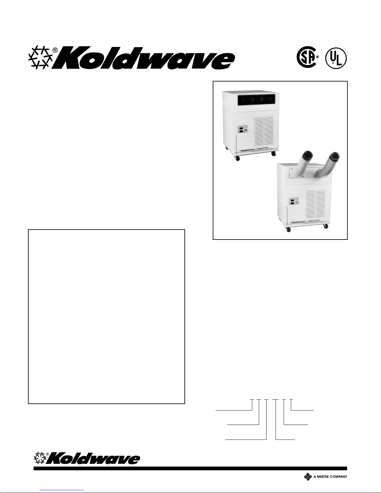
GENERAL DESCRIPTION
The Koldwave Airmaster is a portable air-cooled zone
cooler which directs cool air to specific areas or
objects through four, adjustable, four-way grilles. Many
small computer and telephone rooms, tanning bed
rooms, laboratories, factories, and numerous areas
can be cooled by its indicated cooling capacity. The
Koldwave Airmaster can also be used for back-up
cooling or as an emergency stand-by unit.
The cord-connected Koldwave Airmaster is provided
with heavy-duty casters. The swivel casters provide
handling ease for convenient relocation. This unit is
completely self-contained with the entire refrigeration
system, electrical components, condenser and
evaporator housed in an attractively-designed, painted
metal cabinet.
NOMENCLATURE
2 A K 10 1 1
260 NORTH ELM STREET • WESTFIELD , MA 01085 • Tel No . (413) 564-5520 • F ax No . (413) 564-5815
5211 CREEKBANK ROAD • MISSISSAUGA, ONTARIO L4W 1R3 CANADA • Tel No. (905) 625-2991 • F ax No . (905) 625-6610
Series 1 = 115 Volt
Air Cooled Single Phase
Koldwave Capacity Indicator
KOLDWAVE 2AK (AIRMASTER)
2AK1011 AIRMASTER PRODUCT DATA AND SPECIFICATIONS
COOLING CAPACITY (BTU/HR) & EER
Evaporator Fan Speed
Conditions
67°F DB/57°F WB (54% RH) 9148 6653 9.71 8261 5568 9.31
72°F DB/60°F WB (50% RH) 9627 7113 9.83 8586 5906 9.32
75°F DB/62°F WB (48% RH) 9903 7287 9.86 8867 6103 9.38
80°F DB/67°F WB (52% RH) 10,613 7223 10.13 9749 6051 9.82
95°F DB/75°F WB (40% RH) 11,970 8783 10.00 11,161 7314 9.81
95°F DB/83°F WB (61% RH) 12,985 6021 10.79 11,973 5186 10.42
104°F DB/80°F WB (36% RH)** 12,603 9399 9.67 11,600 7917 9.35
Total Sensible EER* Total Sensible EER*
High Low
ELECTRICAL DATA***
Voltage/Phase/Hertz 115/1/60
Amperage 10.5
Fuse Size (Amps) 15
Watts 1196
Inrush Current (Amps) 69.7
COMPRESSOR (ROTARY)
Horsepower 0.75
Watts 845
RLA 7.4
LRA 44
RPM 3400
Refrigerant R-22
BLOWER (CONDENSER)
Speed
Amps 1.3 0.8
Watts 139 87
RPM 1570 1115
CFM @ 0.0" H2O E.S.P. 440 300
BLOWER (CONDENSER)
Speed
Amps 2.3 1.6
Watts 250 164
RPM 1090 780
CFM @ 0.0 E.S.P. 730 515
CFM @ 0.25 E.S.P. 610 450
Time delay fuses and circuit breakers are recommended.
*EER determined with condenser discharge air ducted into another area on high fan speed.
**Maximum operating condition.
***Electrical ratings per U.L Standard 484 at 95°F DB/75° WB on high speed.
High Low
High Low
CONDENSATE PUMP (OPTIONAL)
Motor HP .0125
Lift (Ft. of H2O) 11.0
Amps .48
Watts 50
EVAPORATOR
Number of Rows 2
Coil Face Area (Ft.2) 1.5
CONDENSER
Number of Rows 3
Coil Face Area (Ft.2) 2.44
EVAPORATOR AIR FILTER SIZE (INCHES)
Width 15.125
Height 18
Thickness 0.5
CONDENSER AIR FILTER SIZE (INCHES)
Width 19.25
Height 16.5
Thickness 0.5
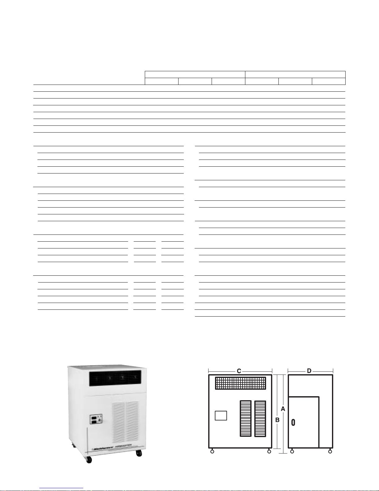
UNIT DIMENSIONS (INCHES)
(A) Height with Casters 34.25
(B) Height without Casters 31.125
(C) Length 25
(D) Depth 24
NET UNIT WEIGHT (LBS.) 182
SHIPPING WEIGHT (LBS.) 207
2

KOLDWAVE 2AK (AIRMASTER)
2AK1411M AIRMASTER PRODUCT DATA AND SPECIFICATIONS
COOLING CAPACITY (BTU/HR) & EER
Evaporator Fan Speed
Conditions
67°F DB/57°F WB (54% RH) 10,714 7736 9.44 9409 6216 8.86
72°F DB/60°F WB (50% RH) 11,200 8328 9.47 9933 6586 8.92
75°F DB/62°F WB (48% RH) 11,534 8538 9.49 10,238 6795 8.93
80°F DB/67°F WB (52% RH) 12,606 8375 9.92 11,262 6757 9.32
95°F DB/75°F WB (40% RH) 14,054 10,248 9.63 12,783 8069 9.20
95°F DB/83°F WB (61% RH) 14,917 6986 10.07 14,054 5902 9.88
104°F DB/80°F WB (36% RH)** 14,668 11,203 9.21 13,626 8725 8.95
Total Sensible EER* Total Sensible EER*
High Low
ELECTRICAL DATA***
Voltage/Phase/Hertz 115/1/60
Amperage 13.8
Fuse Size (Amps) 20
Watts 1563
Inrush Current (Amps) 79.7
COMPRESSOR (ROTARY)
Horsepower 1.0
Watts 1080
RLA 9.7
LRA 54
RPM 3400
Refrigerant R-22
BLOWER (CONDENSER)
Speed
Amps 1.4 0.8
Watts 134 89
RPM 1595 1053
CFM @ 0.0" H2O E.S.P. 400 265
BLOWER (CONDENSER)
Speed
Amps 2.3 1.6
Watts 250 164
RPM 1090 780
CFM @ 0.0 E.S.P. 730 515
CFM @ 0.25 E.S.P. 610 450
Time delay fuses and circuit breakers are recommended.
*EER determined with condenser discharge air ducted into another area on high fan speed.
**Maximum operating condition.
***Electrical ratings per U.L Standard 484 at 95°F DB/75° WB on high speed.
High Low
High Low
CONDENSATE PUMP (OPTIONAL)
Motor HP .0125
Lift (Ft. of H2O) 11.0
Amps .48
Watts 50
EVAPORATOR
Number of Rows 3
Coil Face Area (Ft.2) 1.5
CONDENSER
Number of Rows 3
Coil Face Area (Ft.2) 2.44
EVAPORATOR AIR FILTER SIZE (INCHES)
Width 15.875
Height 18
Thickness 0.5
CONDENSER AIR FILTER SIZE (INCHES)
Width 19.25
Height 16.5
Thickness 0.5
UNIT DIMENSIONS (INCHES)
(A) Height with Casters 34.25
(B) Height without Casters 31.125
(C) Length 25
(D) Depth 24
NET UNIT WEIGHT (LBS.) 185
SHIPPING WEIGHT (LBS.) 210
3
KOLDWAVE 2AK (AIRMASTER)
STANDARD FEATURES/UNIT CONSTRUCTION
FEATURES
• Optional 10' flexible duct extends
up to 10 feet to vent condenser
air.
• Convenient control panel houses
on-off switch, thermostat and
indicator lights.
• Large, heavy-duty casters allow
you to move the Koldwave
®
Airmaster to virtually any location.
• Four way adjustable grilles
control air discharge for even,
comfortable cooling.
• Hinged panel allows easy access
to 5-gallon condensate holding
tank.
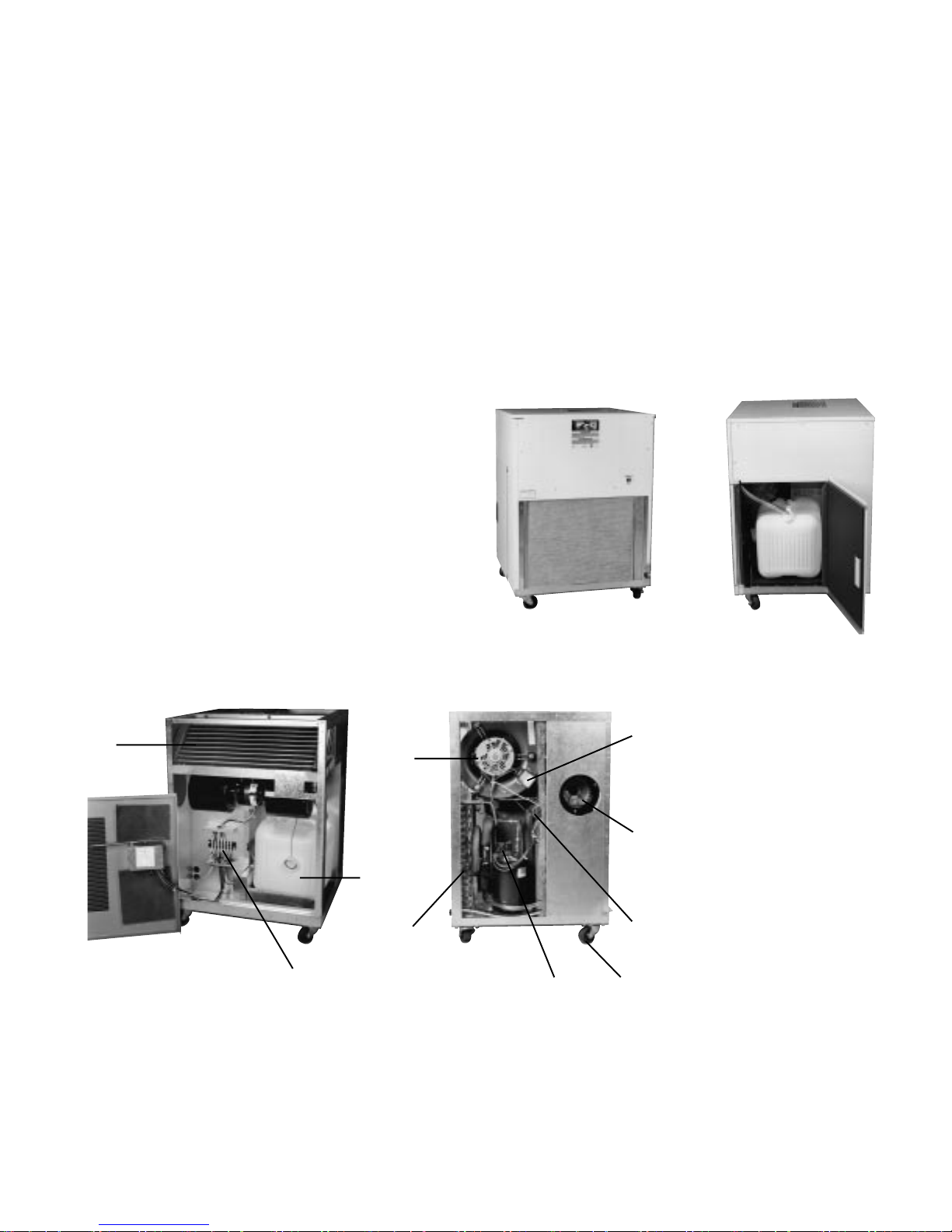
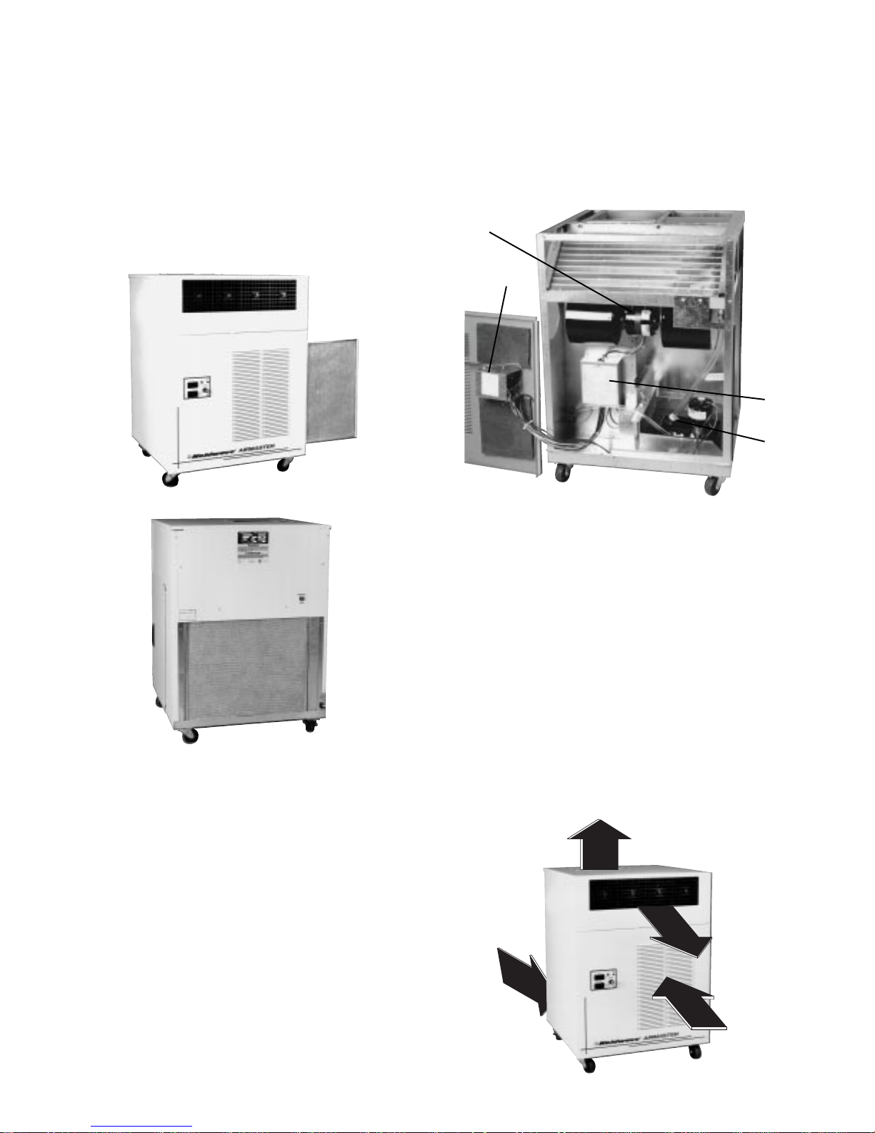
SERVICEABILITY
The Koldwave Airmaster has removable panels to
provide full service accessibility. The interior is divided
into three sections. The upper front face encloses the
evaporator coil and blower assembly. The lower front
section contains the electrical controls, which are
secured to the removable front panel, and the
condensate holding tank an its level detection system.
The rear section encases the compressor, condenser
coil and blower assembly.
Front Left
Side
1
4
3
Back
Right
Side
1. Evaporator Coil
5
2. Terminal Block Enclosure
3. Condensate
Holding Tank
4. Condenser Fan Motor
5. Fan Motor Capacitor
6. Condenser Coil
7. Compressor (Rotary)
9
8. Compressor Capacitor
9. Evaporator Blower
10. Casters
2
6
7
8
10
4

KOLDWAVE 2AK (AIRMASTER)
CABINET
The Koldwave Airmaster cabinet is constructed of 20
gauge, cold rolled steel with painted steel finish for
corrosion protection. It is lined with thermal and sound
absorbent insulation material in the discharge area
and vibration dampening on all panels.
SAFETY ENGINEERED
In addition to the rotary compressor’s overload
protection, Koldwave Airmaster incorporated, within
the refrigeration system a manual reset high pressure
switch for maximum safety of the compressor. The cutout pressure setting is 375 ± 10 psig. In the event that
the high pressure switch setting is exceeded, the
compressor and condenser fan operation will cease.
The compressor and condenser fan can be restarted
by depressing the “reset” button located on the back
panel of the unit. The high pressure switch capillary
line screws onto an access valve on the refrigeration
discharge line to make it possible to remove or replace
a defective control without disturbing the refrigeration
system. The unit also employs an automatic reset
freeze control, located on top of condenser coil, to turn
the entire unit off at low ambients and defrost the
evaporator coil for approximately five minutes.
NOTE: Wait two minutes before restarting unit after
tripping by one of the safety features.
Back
RELIABLE CONTROLS
The self-contained unit maintains the desired amount
of cooling, which can be selected by adjusting the
thermostat to warmer or cooler. The thermostat
sensing bulb is in the return air stream behind the
louvered return air grille and return air filter. The range
of the thermostat is from 65-100° with a differential of
± 3°F.
Rear of
Front Panel
Thermostat
Bulb
The three-position, mode selector rocker switch,
located in the front panel, has three functions:
1. To provide fan only operation when depressed to
the right.
2. To turn the unit off when set in the center position.
3. To activate the cooling mode when depressed to
the left.
1. Nameplate
2. H.P.C. Reset Button
3. Condenser Filter
4. Service Cord
1
2
3
The blue colored light above the thermostat indicates
the thermostat is calling for cooling mode operation.
Compressor may or may not be on, depending on the
thermostat setting. The red, “tank full” warning light
indicates condensate tank is full and needs to be
emptied. The two-position, fan-speed rocker switch,
located below the mode selector switch, provides high
fan speed when depressed to the right and low speed
when depressed to the left.
Mode
Selector
Switch
Cooling Mode
Indicator (Blue)
Tank Full
Indicator (Red)
4
Thermostat
Fan
Speed
Switch
Convenient Control Panel
5
KOLDWAVE 2AK (AIRMASTER)
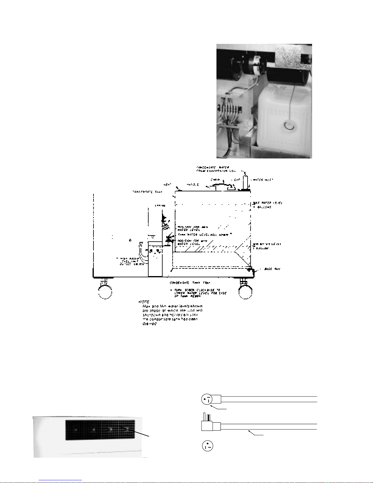
CONDENSATE RESERVOIR TANK
The Koldwave Airmaster incorporates a 5.0 gallon
capacity, polyethylene, condensate drain tank, located
in the lower, front section of the unit. A high water cutout switch is used to stop the entire unit’s operation
automatically when the tank is full of water. An
adjustment screw is provided to set the desired
condensate level where the unit cuts out. Turn screw
clockwise to lower water level and thus decrease the
tank’s weight for emptying. To prevent spillage, the
tank is equipped with a cap, which is chained to the
top of the tank, and a vent for easy drainage.
CAUTION: Turn unit off before emptying tank when
tank light is illuminated.
DISCHARGE AIR GRILLES
The Koldwave Airmaster is equipped with (4) 5" x 5",
four-way adjustable, plastic grilles, located in the upper
front panel, enabling a variety of air flow possibilities.
Pull out each black grille (approximately 3/4") and
rotate to the desired position. Release the grille and
allow it to return to the set position within the cabinet.
By this means, air flow can be positioned in any four
directions.
Adjustable
Air Grilles
SERVICE CORD
The six foot service cord employed in Model
2AK1411M will not fit in the standard household
receptacle. Required is a 20A-125 volt NEMA 5-20
receptacle. Model 2AK1011 uses a standard 15 amp
plug.
PLUG END TERMINATION
JACKET
RECEPTACLE
20A - 125V
NEMA 5-20R
6
KOLDWAVE 2AK (AIRMASTER)
AIR FILTERS
The Koldwave Air master employs two, 1/2" thick,
washable aluminum mesh air filters, located behind
the louvered front (evaporator) panel and beneath the
back (condenser) panel. The evaporator filter can be
easily removed and cleaned; just pull the filter end cap
at the bottom of filter and slide out. The condenser
filter is removed by lifting the tab at bottom of filter,
then pulling toward you and down.
ELECTRICAL
Electrical control is concentrated in an enclosed area
behind the control panel. Electrical interconnection is
achieved via a multi-position terminal strip located in a
junction box fastened to the bulkhead wall.
1
2
3
4
GENERAL AIRFLOW PATTERNS
Condenser air is drawn in through the lower rear
section of the unit and passes through the condenser
coil and extracts heat. The hot air is blown out the
upper exhaust air opening. Evaporator air is taken
through the lower, front, louvered panel and is cooled
by the evaporator coil. It’s then blown in through four,
adjustable, four-way grilles, enabling a variety of
airflow possibilities. Both condenser and evaporative
air inlets are provided with filters.
1. Evaporator Fan Motor
2. Control Enclosure
3. Terminal Block Enclosure
4. Condensate Pump Assembly (Optional)
7
KOLDWAVE 2AK (AIRMASTER)
ACCESSORIES
8
KOLDWAVE 2AK (AIRMASTER)
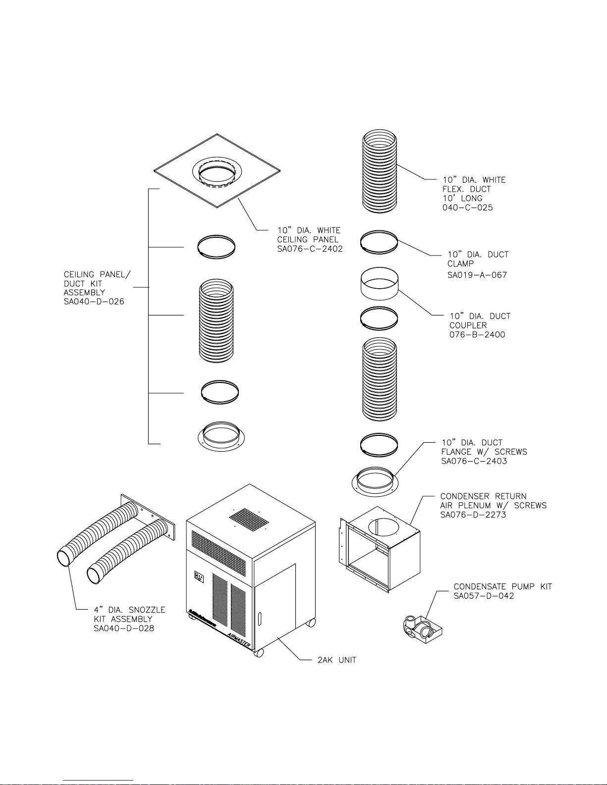
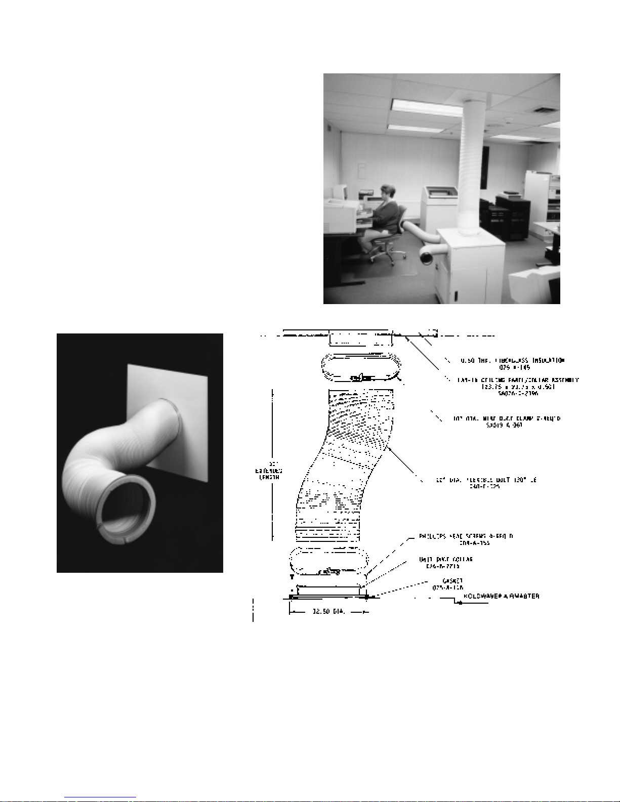
CEILING PANEL/DUCT KIT ASSEMBLY
(OPTIONAL)
A 10" diameter, flexible duct kit assembly extends up
to 10 feet, to vent condenser air or to draw condenser
return air from the ceiling when condenser return air
plenum is used. It comes with 2' x 2' lay-in ceiling
panel/collar assembly, for venting into the plenum area
above the false ceiling, plus a duct collar to attach duct
to unit. Installation of the flexible duct can be achieved
in the following manner:
1. Slip one end of the duct over the lay-in ceiling
panel/collar assembly and other end over the unit
duct collar.
2. Clamp duct to lay-in ceiling panel/collar assembly
and unit duct collar (see “Duct Design” for details.
3. Place the 2' x 2' lay-in ceiling panel in the false
ceiling directly above the unit.
4. Screw duct collar to unit with four screws provided.
9
KOLDWAVE 2AK (AIRMASTER)
DUCT DESIGN
Condenser Duct
Should a longer 10" diameter duct be needed on the
condenser discharge, 10 foot flexible ducts may be
coupled together up to a maximum equivalent length
of 60 feet (allow 6 feet for every 90° bend).
10" Diameter Duct Clamp SA019-A-067
Duct Clamps
Two 10" diameter wire duct clamps are used to secure
the condenser air exhaust duct to the lay-in ceiling
panel/collar assembly and the Koldwave Airmaster
exhaust duct collar.
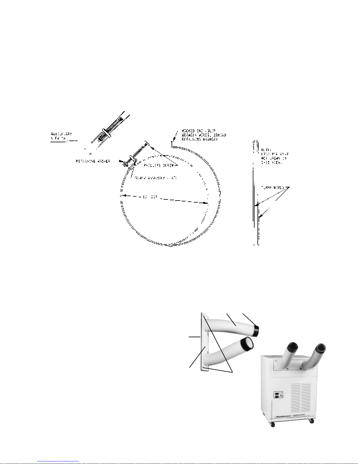
DISCHARGE AIR SNOZZLE® KIT ASSEMBLY
(OPTIONAL) SA040-D-028
A 20 gauge painted steel air discharge snozzle
mounting plate assembly can be furnished as an
optional item. Its purpose is to accommodate various
spot cooling applications, where air can be aimed and
concentrated on the object to be cooled. The plate is
designed with two 4" diameter, 16" compressed and
22" long extended flexible air duct snozzles®. The use
of the snozzles® will derate the capacity by
approximately 13%. The snozzle® plate is mounted
over the evaporator air discharge opening by 1/4 turn
Pawl Latch fasteners for each removal. It is secured in
place by tightening the four fasteners provided with the
plate assembly. It can be removed easily by tur ning
the fastener on quarter turn counter-clockwise.
3
5
®
4
2
1. 1/4 Turn Pawl
Latch Fasteners
2. Mounting Plate
3. Snozzle Caps
4. Insulation
5. Snozzle Duct
1
10

KOLDWAVE 2AK (AIRMASTER)
11

CONDENSATE RETURN AIR
PLENUM (OPTIONAL)
A 20 gauge, painted steel,
condenser return air plenum can
be furnished for applications of the
Koldwave Airmaster as a room air
conditioner. This plenum is
designed for use with a flexible
duct kit assembly. The duct collar
of the duct kit assembly can be
secured with four screws over a
10" diameter hole in the top of the
plenum. The duct can then be
connected to the lay-in ceiling
panel, so condenser return air is
drawn from the false ceiling above
the unit.
The plenum is mounted to the
condenser air intake by sheet
metal screws. A filter frame is
incorporated in its design to allow
easy removal of the filter for
cleaning from the right side of the
unit. The filter frame is made to
accept the unit’s standard
condenser air filter with the filter
handle relocated from the bottom
to side of filter at installation.
SA076-D-2273
KOLDWAVE 2AK (AIRMASTER)
NOTE: See “Application” section
for typical installation.
12
KOLDWAVE 2AK (AIRMASTER)
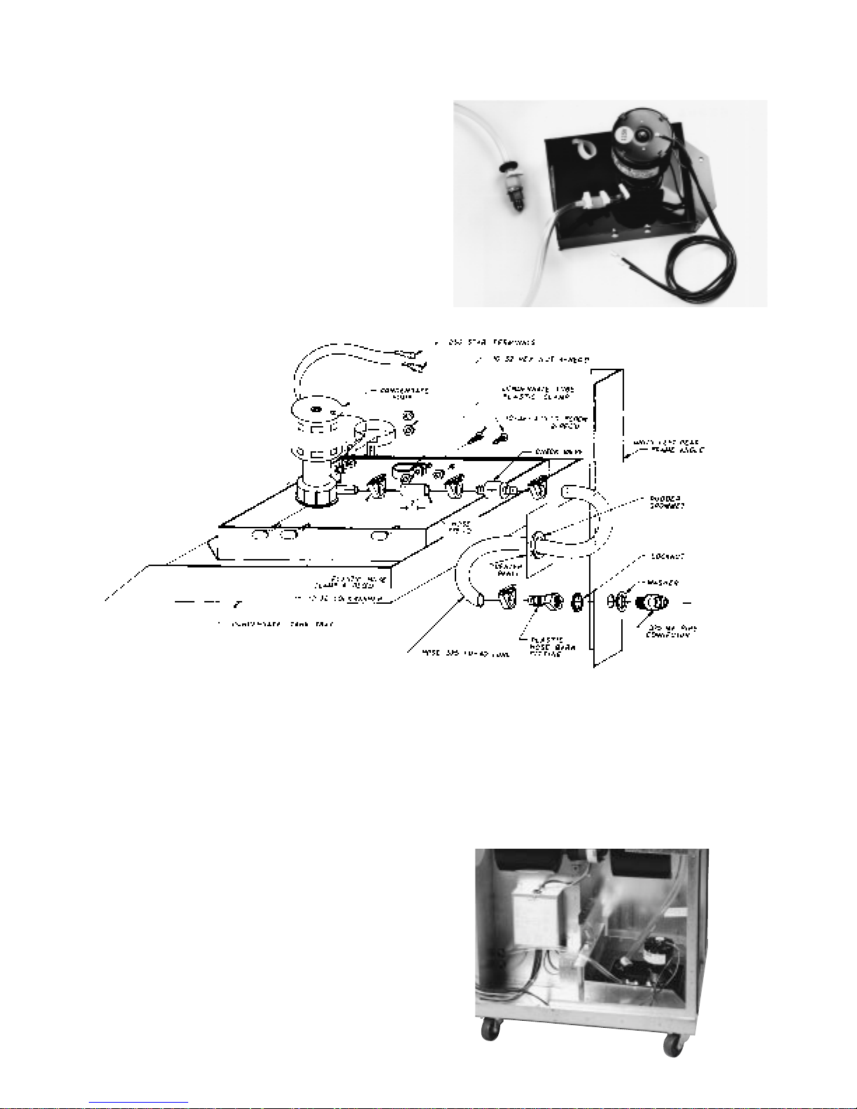
CONDENSATE PUMP KIT (OPTIONAL) SA057-D-042
A condensate pump, capable of pumping against an
11 foot head, can be installed for positive removal of
evaporator condensate. This kit is a convenience for
those who do not wish to empty the five gallon
condensate tank periodically, especially for units with
permanent installation. At the condensate pump, a
check valve is inserted in the hose and secured by
plastic clamps. The installation can be accomplished
by following the simple steps outlined in “procedures to
install condensate pump kit assembly”.
PROCEDURE TO INSTALL
CONDENSATE PUMP KIT ASSEMBLY
1. Disconnect unit from power source.
2. Pull out clear plastic drain hose from inside of tank
and remove tank from hinged tray.
3. Mount pump kit assembly in hinged tray using the
two holes provided in the tray flange facing front
panel by using the two machine screws and hex
nuts.
4. Route clear plastic hose from pump through a hole
in the bulkhead below the terminal strip enclosure
and up to another hole located in the left rear frame
angle. Both holes are plugged by knockout buttons
which should be removed. Fit a 1-1/8" O.D. rubber
grommet into the hole in bulkhead prior to inserting
plastic hose through it.
5. Insert a 3/8" MF pipe connector into 1" O.D. steel
washer and into the left rear frame angle. Lock
connector in the frame angle with a locknut.
6. Screw tightly the 3/8" FPT x 3/8" plastic hose barb
into the 3/8" MF pipe connector.
7. Insert plastic hose from pump into hose barb and
clamp with a #30 nylon hose clamp.
8. Connect pump wire leads to terminal strip positions,
number 1 and 2.
9. Insert plastic drain hose from evaporator pan into
the drain tube clamp provided in the pump kit
assembly (see the drawing).
13

KOLDWAVE 2AK (AIRMASTER)
APPLICATIONS
ZONE COOLER
Koldwave Airmaster can be employed in an open
environment as a zone cooler to cool a specific object
which the evaporator grilles or the optional snozzles®
direct the air toward. In this application, ducts for
condenser air intake and hot air exhaust are not
required. Zone cooling provides convenient,
economical and energy efficient air conditioning in
areas where cooling the entire environment is
impractical. It directs cool air only where aimed and
needed without wasting it elsewhere. Note that even
though the object is cooled with a concentrated air
supply, the surrounding area will slightly be heated up
by the condenser’s hot exhaust air. Cooling tanningbed rooms, beauty parlors and vehicle maintenance
department are just a few areas that can benefit from
this application. The figure below shows a typical
example of how the unit can be applied.
AREA COOLER
In a similar application where a specified area needs
to be cooled a condenser hot air exhaust duct may be
employed as shown in the figure below. Refer to
(optional) “Flexible Duct Kit Assembly” for more
details. Evaporator discharge grilles (as standard) or
optional snozzles may be used.
While evaporator discharge air cools the air directly in
front of the unit, warm room air will be drawn into the
rear of the unit to cool the condenser and then
discharged into the false ceiling. The net effect will be
a cooler area all around the unit.
When installed in an enclosed area used as a room air
conditioner, the Koldwave Airmaster will require makeup air for condensing. A return air plenum and return
air ducting are available to supply condensing air from
outside the conditioned space.
14

KOLDWAVE 2AK (AIRMASTER)
ROOM AIR CONDITIONER
Koldwave Airmaster may also be used as a room air
conditioner to cool the entire enclosed space it is
placed in. In this application, hot exhaust air venting
and condenser air intake ducting are definitely needed.
This can be accomplished by employing the “Flexible
Duct Kit Assembly” (optional) and the “Condenser
Return Air Plenum” (optional) as specified in the
“Optional Features” section. See figure below for
orientation of flexible ducts.
The condenser coil is cooled by the air drawn from the
false ceiling. The air passes through the hot condenser
coil, gets heated up, then discharges to an area
outside the room being cooled (outdoors).
INSTALLATION INSTRUCTIONS
Before installing: Check the air conditioner/spot cooler
for any shipping damage. Air conditioners are
thoroughly inspected at the factory and carefully
packed. If any damage is evident, file a claim with the
delivering carrier immediately.
Electrical requirements: Check the data plate on the
unit to make certain that the proper power is available.
Refer to “Specifications” section for voltage, fuse
requirements and proper NEMA receptacles. Check for
proper wall outlet as described in “Standard Features”
section. Operating the unit on improper voltages will
void the warranty.
CAUTION: An extension cord can be used provided
it is rated at least 20 amps @ 115 volts with
grounding-type attachment plug and grounding type
connector (load fitting).
Koldwave Airmaster portable air conditioner/spot
cooler requires minimal installation. It merely plugs
into a NEMA 5-20R receptacle for 2AK1411M or 5-15R
for 2AK1011 and immediately begins to cool. The
entire system is built into one compact unit which can
be moved and installed easily.
15

KOLDWAVE 2AK (AIRMASTER)
CHECK OUT OF UNIT OPERATION
Koldwave Airmaster portable spot cooler provides fan
only air circulation and cooling modes. This is
accomplished by setting the controls to operate in any
of the following:
Fan Only
Plug unit in. Depress the upper mode selector switch
to the right for fan operation. Depress the lower fan
speed selector switch to the left for low fan speed and
to the right for high speed.
Cooling Cycle
Depress the upper mode selector switch to the left for
cooling. Set the thermostat knob below actual room
dry bulb temperature level. Blue colored light located
next to the upper rocker switch on the panel should
illuminate, indicating the cooling mode of operation.
Allow unit to run fan speed set on high for twenty
minutes. Record temperature of air entering filter and
temperature of air leaving the discharge grille. In a
room of approximately 80°F dry bulb, air temperature
coming from the grille should be approximately 15°F
cooler than air returning to filter. This cycle reduces the
dry bulb temperature and it lowers the wet bulb
temperature by condensing water on the cooling coil
surface. The red colored light located next to the blue
colored light on the panel should illuminate when
condensate tank is full. Refer to “Condensate
Reservoir Tank” section.
TROUBLESHOOTING GUIDE
SERVICE PROCEDURES
Always disconnect power and discharge capacitors
before servicing. Before troubleshooting this system,
read this manual to determine electrical power and
installation requirements to allow the spot cooler to
perform at its maximum efficiency. Refer to general
description, wiring diagrams and photographs to get
an understanding of how the unit functions.
Service other than routine maintenance should be
performed only by a qualified refrigeration service
person. In service/troubleshooting, there is no
substitute for a good understanding of the Koldwave
Airmaster modes of operation, control systems,
components and safety systems (see service
performance chart).
SYSTEM PERFORMANCE CHART
The chart below shows suction and discharge
pressures (PSIG), plus total amp draw with evaporator
fan on high speed, with condenser motor on high
speed and with condenser blower baffle. The
condenser discharge air is ducted into another area
with a 10" diameter, 10' long flexible duct.
Ambient Temperatures V ersus
Suction and Discharge Pressures
Room
Model
2AK1011
2AK1411M
Use the above chart for reference when suction and discharge
pressure and total amps are a determining factor in analyzing the
problem. Refer to troubleshooting guide when above data can be
useful in determining overcharge or undercharge of unit.
Conditions
104°F DB/80°F WB
95°F DB/83°F WB
95°F DB/75°F WB
80°F DB/67°F WB
75°F DB/62°F WB
72°F DB/60°F WB
67°F DB/57°F WB
104°F DB/80°F WB
95°F DB/83°F WB
95°F DB/75°F WB
80°F DB/67°F WB
75°F DB/62°F WB
72°F DB/60°F WB
67°F DB/57°F WB
Suction
Pressure
104
100
93
78
71
69
65
93
79
93
79
71
68
63
Discharge
Pressure
317
271
277
216
198
187
171
321
290
282
224
207
193
178
Total
Amps
11.5
10.6
10.5
9.2
8.8
8.6
8.3
13.9
12.9
12.7
11.1
10.6
10.3
9.8
16

KOLDWAVE 2AK (AIRMASTER)
TROUBLE SHOOTING GUIDE continued
PROBLEM SYMPTOM POSSIBLE CAUSE REMEDY
Unit does not
operate.
Insufficient cooling.
Entire unit does not
operate.
Unit starts, but stops
immediately.
Unit operates, but
stops after a few
minutes.
Insufficient air flow
through evaporator.
Evaporator discharge
air not cool.
Compressor motor not
running.
1. Power Interruption.
2. Defective tank full unit cutout switch.
3. Condensate tank could be
full, but red light might be
defective.
1. Defective compressor
overload relay.
2. Defective compressor motor.
3. Defective run capacitor.
1. Defective compressor motor.
2. Defective over load relay.
3. Defective high pressure
switch.
4. Loose connection in
electrical circuit.
5. Manual reset button out on
HPC.
6. Unit overcharged.
7. Dirty condenser coil and
filter.
8. Condensate tank right at trip
point.
9. Condenser fan running at
high ESP.
1. Improper size of unit.
1. Dirty air filter in unit.
2. Dirty evaporator or
condenser.
3. Ice on evaporator coil.
4. Obstructed intake.
5. Defective condenser fan
motor or its capacitor.
1. Refrigerant leak.
1. Defective compressor motor.
2. Defective compressor
capcitor.
3. Defective over load relay.
4. Defective thermostat.
5. Defective wiring connection.
6. Defective wiring.
1. Check external power supply.
2. Check and replace.
3. Check tank and replace red
light if defective.
1. Replace after checking current.
2. Remove and replace.
3. Check and repalce.
1. Check and replace.
2. Replace after checking current.
3. Check cut-out setting and
replace if defective.
4. Trace loose wire(s) and firm up
connection.
5. After diagnosing and correcting
cause for unit trip out, begin
unit operation by depressing
the red button located in the
back panel.
6. Purge some refrigerant.
7. Clean filter and condenser coil.
8. Empty tank.
9. Check fan speed and correct.
1. Check if the unit is undersized
for the load, Add supplemental
unit(s).
1. Clean air filter.
2. Unusual condition requires
cleaning.
3. Defrost. Use fan only by
depressing the upper rocker
switch to right.
4. Remove obstuction.
5. Check and replace.
1. Locate leak and repair.
Evacuate and recharge.
1. Check and replace.
2. Check and replace.
3. Check and replace.
4. Check and replace.
5. Check and repair.
6. Check and replace.
No cooled air discharge.
Evaporator blower
motor not running.
1. Defective fan motor.
2. Defective fan motor
capacitor
3. Defective wiring connection.
4. Defective fan speed switch.
5. Defective thermostat.
17
1. Check and replace.
2. Check and replace.
3. Check and repair.
4. Check and replace.
5. Check and replace.

KOLDWAVE 2AK (AIRMASTER)
PROBLEM SYMPTOM POSSIBLE CAUSE REMEDY
Evaporator blower not
running up to full speed.
Evaporator fan runs,
but compressor does
not start.
Abnormal noise.
Room air temperature
discharged through
grilles.
1. Low voltage to unit.
2. Defective motor capacitor.
3. Blower wheel rubbing
against housing.
1. Low voltage to unit.
2. Thermostat.
3. Loose or defective wires.
4. Stuck compressor.
5. Compressor shorted, open
or burned.
6. Shorted or open run
capacitor.
7. HPC holding unit off.
1. Loose compressor mounting
nuts.
2. Defective, improper or worn
rubber grommets on the
compressor mounting bolts.
3. Copper Tube vibrating.
4. Loose cabinet or internal
component
5. Loose blower wheel.
6. Blower wheel hitting shroud.
7. Blower bearing defective.
1. Determine reason and correct.
2. Replace capacitor.
3. Inspect wheel alignment and
correct.
1. Check power supply for proper
voltage at unit; ± 10% of rated
nameplate voltage.
2. Check the temperature control
for loose wires. Firm any loose
connections. Replace if
defective.
3. Tug on wires to see if they will
separate from connections.
Replace terminals if necessary.
4. Try a start capacitor across the
run capacitor momentarily
(three seconds).
5. Check for shorts, opens and
grounds. Remove and replace
compressor.
6. Remove and replace.
7. Check condenser fan.
1. Tighten.
2. Replace.
3. Adjust by bending slightly to
firm position. Separate tubes
touching cabinet or each other.
4. Check and tighten loose
screws.
5. Tighten scres on blower wheel
to shaft.
6. Adjust wheel position on motor
shaft.
7. Replace blower motor.
Water leaking from unit
1. Leaking evaporator or
condensate pan.
2. Dirty evaporator coil.
3. Defective drain hose
(clogged or loose
connection).
4. Defective microswitch
causing condensate tank to
overflow.
5. Hole or crack in condensate
tank.
18
1. Locate leak and repair pan.
2. Check to see if the elevation is
over 11 ft. (if it is over 11 ft., a
larger condensate pump is
required). Otherwise, replace
pump if defective. Pump will
operate properly against 11 ft.
of water total head pressure on
pump. If combination of vertical
height and horizontal drain line
exceeds 11 ft. of water
pressure drop, problems may
arise.
3. Repair or replace.
4. Remove and replace.
5. Remove and replace.

KOLDWAVE 2AK (AIRMASTER)
INSPECTION AND REPAIR OF ELECTRICAL SYSTEM
Always disconnect power and discharge capacitors
before servicing.
Thermostat
Check for continuity across terminals 1 and 2 of the
thermostat. At normal temperature (65°F or higher)
there is continuity across those two terminals. If
continuity is broken across the terminals, replace the
thermostat.
Fan/Off/Cool/Switch
At each position of the fan/off/cool switch, there should
be continuity across the following terminals.
Switch Conducting
Position Terminals
Off None
Fan Center and Left
Cool Center and Right
If there is no switch continuity in the fan and cool
position, replace the switch.
Fan Speed Switch
Switch Conducting
Position Terminals
High Speed Center and Left
Low Speed Center and Right
There should be continuity across the above terminals.
If none, replace switch.
Tank Full Unit Cut-Out Switch
Depress the microswitch to check for continuity. If
there is no continuity between common and normally
open terminals, replace the switch.
High Pressure Switch
Check for continuity across terminals 1 and 2 of the
high pressure switch. At normal pressure when the unit
is not operating, there is continuity across the two
terminals. If continuity is interrupted across the
terminals, replace the high pressure switch.
Compressor Motor
Measure resistance across the terminals of the
compressor motor.
Resistance between C-R at 70°F
approximately 0.65 OHMS ± 10%
Resistance between C-S at 70°F
approximately 4.50 OHMS ± 10%
Replace compressor when resistance is not at the
stated values.
Compressor Overload Relay
Check for continuity across overload relay’s tow
terminals. At normal room temperatures, there is
continuity across the two terminals. If no continuity
exists, replace the over load relay.
Compressor and Fan Motor Capacitors
Before and after the test, always short across two
terminals to discharge electrostatic charges. Set the
ohmmeter to 100 OHMS range and place its two
probes against the two terminals of the capacitor. At
first, the ohmmeter should indicate zero OHMS, then
the meter reading should gradually approach infinity. If
the ohmmeter shows infinity from the outset or the
meter reading does not move from zero OHMS,
replace the capacitor.
Condenser Fan Motor
Measure resistance across the terminals of the fan
motor.
Resistance across white and black
7.42 OHMS ± 10% at 25°C
Resistance across red and black
11.94 OHMS ± 10% at 25°C
Resistance across white and red
19.36 OHMS ± 10% at 25°C
Cut-out pressure – 375 psig
Cut-in (restart) pressure – 275 psig
When resistance is not within these stated values,
replace the fan motor.
19

KOLDWAVE 2AK (AIRMASTER)
Evaporator Fan Motor
Resistance across white and black
22.5 OHMS ±10% at 25°C
Resistance across red and black
26.2 OHMS ± 10% at 25°C
Resistance across white and red
48.7 OHMS ± 10% at 25°C
When the resistance is not within these stated values,
replace the fan motor.
Condensate Pump Motor (optional)
Measure resistance across the terminals of the pump
motor. 31.0 OHMS ± 8% at 25°C. when the resistance
is not within these stated values, replace the pump
motor.
Tank Full and Cooling Mode Pilot Lights
Make a test circuit as shown in figure below. If the light
fails to illuminate, replace it.
CONTROL
ENCLOSURE
TERMINAL BLOCK
ENCLOSURE
20

KOLDWAVE 2AK (AIRMASTER)
INSPECTION AND REPAIR OF REFRIGERATION LEAK
WARNING: All repair work on the refrigeration
system must be done by a qualified service
technician who is certified to handle refrigerants.
Carefully check all connection and every part for leaks
whenever the refrigerant system is repaired. Use a
leak detector or the halide torch to inspect the system.
PARTS REPLACEMENT PROCEDURE
When repairing a leak, use dry nitrogen gas. During
brazing, the inside of the pipe undergoes oxidative
reaction due to the brazing flame. It is desirable to use
a slightly reduced flame. Conduct dry nitrogen gas
through the refrigerant piping to prevent oxidation.
Always evacuate refrigeration system thoroughly with
a vacuum pump before charging the system with
refrigerant.
Always disconnect power and discharge capacitors
before servicing.
Thermostat and Rocker Switches
1. Remove evaporator filter by pulling filter end cap at
bottom and slide out.
2. Open hinged right side bottom panel.
3. Remove four Phillips head screw from front right
and left corner posts of the chassis holding front
panel. Remove front panel and pull away towards
left. Unscrew two sheet metal screws securing
cover to control box.
4. Remove thermostat sensor bulb from clip secured
on control box cover. Disconnect wires from
controls. Pull thermostat knob out and unscrew hex
nut retaining thermostat.
5. Remove wires from rocker switches, press down
four positive-locking legs of rocker switches used
for snap-in mounting and pull out. Replace controls
and reverse above procedures.
Pilot Lights
To remove pilot lights, remove evaporator filter and
front panel, disconnect wires from controls, bend
Tinnerman clip retaining light and pull out. Install new
light(s) reversing above procedure.
Condenser Fan Motor
To gain access to condenser fan motor, remove left
hand side, top, back and front cabinet panels. Remove
fan motor wires from capacitor, high pressure switch
and terminal strips. Loosen set screw in blower wheel.
Loosen clamp around motor housing and remove
motor. Unfasten clamp around motor and replace
motor, reversing above procedures.
Condenser Blower Housing
To replace the condenser blower housing, first remove
condenser fan motor as described in “Condenser Fan
Motor”. Unscrew four 1/4-20 bolts and four sheet metal
screws holding blower to chassis and top panel.
Remove six self-tapping screws off the bracket
mounted on the housing. The blower wheel can be
replaced by pulling it out through the blower housing’s
discharge opening after removing the blower cut-off
plate. Replace housing, reversing the above
procedure.
Evaporator Fan Motor Assembly
Remove the left hand side and front cabinet panels.
Open hinged right side bottom panel by pushing on the
identified area. Remove fan motor wires from terminal
strip and fan speed rocker switch. Loosen set screw in
blower wheels. Remove locknuts retaining motor to
motor base. Remove motor and blower housings.
Blower wheels can be removed after taking off the
outside blower rings. No you can replace fan motor,
housings or wheels without removing the fan board by
reversing the above procedure.
Tank, Terminal Strip and Microswitch
The lower front section of Koldwave Airmaster
encloses the electrical terminal strips and the
condensate holding tank and its water level detection
system. Access can be gained to those parts by simply
removing the front panel.
Compressor and Running Capacitor
To service the compressor and its running capacitor,
remove the left hand side panel.
21

KOLDWAVE 2AK (AIRMASTER)
High Pressure Control
To gain access to the high pressure
control, remove the condenser air filter by
holding tab at bottom of filter, lifting filter
and pulling toward you and down. Remove
back and left hand side cabinet panels by
removing 13 Phillips head screws.
Remove screw from high pressure control
plastic cover and pull cover off and three
wires behind it. Unscrew two machine
screws holding control to condenser coil
flange. Loosen 3/8" flare nut securing
control capillary tube to Shrader fitting in
compressor discharge line. Replace high
pressure control, reversing above
procedure.
Condenser Fan Motor Speeds
Koldwave Airmaster is shipped from
factory with condenser fan motor wired on
low speed. A noise baffle is mounted
partially over the condenser blower
opening. The external static pressure
(E.S.P.) at the condenser discharge
cannot exceed 0.25" of water. When
employing more than 10 ft. of duct, the
condenser fan should be wired on high
speed and the noise baffle removed. This
will prevent the unit from tripping on its
high pressure control at high ambients.
To change condenser fan speed from low
to high, replace black wire from fan at high
pressure control with taped red wire from
fan motor (see paragraph on high
pressure control above to gain access to
high pressure control).
Removal of Noise Baffle
To gain access to noise baffle, remove the
four discharge grilles by pulling out each
grille (approximately 3/4") and pushing
down to snap out the tip spring and lift out.
Unscrew (12) Phillips head screws to
remove top, and loosen left and right side
cabinet panels. Remove condenser blower
wire mesh guard. The noise baffle is
located between the condenser blower
housing and the insulation (see figure
below). Remove baffle and assemble
remaining parts by reversing above
procedure.
22

KOLDWAVE 2AK (AIRMASTER)
CONDENSER BLOWER MOTOR ASSEMBLY
EVAPORATOR BLOWER MOTOR ASSEMBLY
23

KOLDWAVE 2AK (AIRMASTER)
PREVENTATIVE MAINTENANCE
Always disconnect power and discharge capacitors
before servicing. Koldwave Airmaster portable zone
cooler has been designed to give maximum
performance and reliability with minimum
maintenance. Maintenance of the system is
concentrated in three areas covered as follows.
Blower Motors
The only required maintenance to the condenser and
evaporator blower motors is to oil them annually. This
can be accomplished by following these simple steps:
1. Remove left hand side panel to gain access to
condenser blower motor. Access can be attained to
the evaporator blower motor by removing the front
panel.
2. Remove yellow oil plugs form oil ports.
3. Add 30 drops (1/5 teaspoon) SAE 20 non-detergent
oil into the ports.
4. Replace yellow oil plugs.
Filters
The life of a filter depends entirely on its environment
and use. It is recommended that air filters be inspected
on a regular basis every five to six weeks. A clogged
filter will cause the unit to operate at greatly reduced
efficiency. This unit employs two 1/2" thick, washable,
aluminum mesh air filters located beneath the louvered
front (evaporator) panel and beneath the back
(condenser) panel. The evaporator filter can easily be
removed and cleaned; just pull filter end cap at bottom
of filter and slide out. The condenser filter is removed
by holding tab at bottom of filter, lifting and pulling
toward you and down. The filters must be washed
periodically when needed. This may be done as follow:
1. Soak filter in solution of warm water and detergent
for 15 minutes.
2. Rinse in clean, hot water and shake excess
moisture from filter.
3. Spray one side of filter with light film of oil.
4. Reinstall with oiled surface facing out from unit.
Condensate Pump (optional)
The condensate pump is located in the lower front
section of the unit. To gain access to condensate
pump, open access door on right hand side of unit.
The pump motor requires oiling every six months with
SAE 20 non-detergent oil. The pan beneath the
condensate pump should be cleaned when mineral
deposits are visible. A clean pan will prolong the life of
the pump and its operation.
24

KOLDWAVE 2AK (AIRMASTER)
General
Always disconnect power and discharge capabilities
before servicing.
If the necessary maintenance steps outlined above are
carried out regularly, the unit will provide long and
reliable service which should only be serviced by a
fully qualified service technician.
If you experience any problems or have comments
about your Koldwave product, we are always pleased
to hear from you. This the essential way in which we
can improve our equipment and assist you in meeting
you requirements.
25

KOLDWAVE 2AK (AIRMASTER)
26

KOLDWAVE 2AK (AIRMASTER)
27

KOLDWAVE 2AK (AIRMASTER)
28

KOLDWAVE 2AK (AIRMASTER)
KOLDWAVE AIRMASTER 2AK
SERVICE AND REPLACEMENT PARTS LIST
PART # DESCRIPTION 2AK10 2AK14
STRAINERS
010-A-050 STRAINER #750011-6 X X
ASSEMBLIES, STRAINER AND CAP TUBE
SA010-A-099 STRAINER CAP TUBE ASSEMBLY X
SA010-A-098 STRAINER CAP TUBE ASSEMBLY X
BLOWERS AND BLOWER ACCESSORIES
013-A-151 BLOWER WHEEL S52-34/18-1/2 CW X X
013-A-152 BLOWER WHEEL S52-33/18-1/2 CCW X X
013-C-154 BLOWER HOUSING #450C EVAPORATOR X X
013-C-155 BLOWER ASSEMBLY 90-7T CONDENSER X X
013-B-153 INLET RING #517 X X
COMPRESSORS
020-A-233 COMPRESSOR RK124AT X
020-A-261 COMPRESSOR 2P17S3R1268 X
ELECTRICAL COMPONENTS
025-A-645 SERVICE CORD 16/3 15 AMP 115V. X
025-A-624 SERVICE CORD 14/3 20 AMP 115V. X
025-A-616 RED INDICATOR LIGHT 3LF4LRN1-20L 115V. X X
025-A-617 BLUE INDICATOR LIGH 3LF4LRN1-30L 115V. X X
025-A-608 ROCKER SWITCH TIGM721 COOL/OFF/FAN X X
025-A-609 ROCKER SWITCH TIGB51 LO/HI X X
SA025-A-618A MICROSWITCH BA-2RV-A2 X X
FILTER/AIR
030-A-041 EVAPORATOR FILTER 15-7/8 X 18 X X
030-A-055 CONDENSER FILTER 16-1/2 X 19-3/8 X X
EVAPORATORS
031-A-215 EVAPORATOR COIL #61488 X
031-A-208 EVAPORATOR COIL #61259 X
CONDENSERS
031-A-216 CONDENSER COIL #61489 X X
MOTORS/BLOWERS
050-D-146 EVAPORATOR 7189-6316 X X
050-D-145 CONDENSER 7121-2186 X X
CAPACITORS/MOTORS
017-A-010 RUN CAPACITOR 25 MFD @ 370V. X X
017-A-099 RUN CAPACITOR 5 MFD @ 370V. X X
CASTERS
021-A-044 CASTERS 121-2.5 (4 BOLT MOUNT) X X
CONTROLS
066-A-090 HIGH PRESSURE SWITCH G23-5304-37 X X
066-A-104 DEFROST CONTROL A30-2316-00 X X
066-A-098 THERMOSTAT C12-2027 X X
CAPILLARY TUBES
067-A-285 CAPILLARY TUBE .049 X 56" 2 3
DISCHARGE GRILLES
SA038-D-013 GRILLE ASSEMBLY W/SPRING CLIP X X
076-A-921 SPRING CLIP XX
KNOBS AND HANDLES
041-A-015 CONTROL KNOB G-11-ML X X
042-A-016 DOOR PULL 14208-3740 X X
ASSEMBLIES/CABINET
076-C-2214 LEFT SIDE PANEL X X
076-C-2216 RIGHT SIDE PANEL X X
076-D-2210 FRONT PANEL W/SILK-SCREEN X X
076-D-2209 TOP PANEL XX
076-C-2224 REAR PANEL XX
076-C-2217 ACCESS DOOR X X
29

KOLDWAVE 2AK (AIRMASTER)
KOLDWAVE AIRMASTER 2AK
SERVICE AND REPLACEMENT PARTS LIST
PART # DESCRIPTION USAGE
OPTIONAL ACCESSORIES FOR 2AK10/14
SA019-A-067 10" DIAMETER DUCT CLAMP
SA040-D-026 10" DIAMETER CEILING PANEL/DUCT ASSEMBLY KIT
SA019-D-028 4" DIAMETER SNOZZLE KIT ASSEMBLY DIRECTIONAL COOLING
SA076-C-2403 10" DIAMETER DUCT FLANGE
SA057-D-042 CONDENSATE PUMP KIT 115V. REMOVAL OF CONDENSATE
SA076-C-2402 10" DIAMETER CEILING PANEL
040-C-025 10" DIAMETER WHITE FLEX DUCT
076-B-2400 10" DIAMETER DUCT COUPLER
SA076-D-2273 CONDENSER RETURN AIR PLENUM
SECURE CEILING PANEL TO
FLEXIBLE DUCT AND EXHUAST FLANGE
EXHAUSTING CONDENSER DISCHARGE AIR
INTO DROP-IN CEILING
FLANGE TO ATTACH EXHAUST DUCT
TO TOP PANEL OF UNIT
2' X 2' LAY-IN PANEL FOR DUCTING
CONDENSER DISCHARGE AIR
WHEN ADDITIONAL LENGTH IS NEEDED FOR
CONDENSER DISCHARGE AIR
TO JOIN ADDITONAL LENGTHS OF
CONDENSER DISCHARGE FLEXIBLE AIR DUCT
ELIMINATES USING CONDITIONED AIR/
RE-CIRCULATEDAIR FOR RETURN
30

KOLDWAVE 2AK (AIRMASTER)
LIMITED W ARRANTY
The Manufacturer warrants to the original owner that the Product will be free from defects in material or workmanship
for a period not to exceed one (1) year from start-up or eighteen months from date of shipment from the factory,
whichever occurs first. If upon examination by the Manufacturer, the Product is shown to have a defect in material
or workmanship during the warranty period, the Manufacturer will repair or replace, at its option, that part of the
Product which is shown to be defective.
The Manufacturer further warrants that the sealed refrigeration system (the product’s compressor, condenser, and
evaporator) will be free from defects in materials and workmanship for five (5) years from date of start-up or sixtysix (66) months from date of shipment from the factory, whichever occurs first. If upon examination by the
Manufacturer the Product is shown to have a defect in material or workmanship during the warranty period, the
Manufacturer will repair or replace, at its option, that part of Product which is shown to be defective. Electrical
parts (such as relays, overloads, capacitors, etc. …) are included in the one year limited warranty but not with the
five year limited warranty of the sealed refrigeration system.
This limited warranty does not apply:
(a) if the Product has been subjected to misuse or neglect, has been accidentally or intentionally damaged,
has not been installed, maintained or operated in accordance with the furnished written instructions, or
has been altered or modified in any way.
(b) to any expenses, including labor or material, incurred during removal or reinstallation of the Product.
(c) to any workmanship of the installer of the Product.
This limited warranty is conditional upon:
(a) shipment, to the Manufacturer, of that par t of the Product thought to be defective. Goods can only be
returned with prior written approval from the Manufacturer. All returns must be freight prepaid.
(b) determination, in the reasonable opinion of the Manufacturer that there exists a defect in material or
workmanship.
Repair or replacement of any part under this Limited Warranty shall not extend the duration of the warranty with
respect to such repaired or replaced part beyond the stated warranty period.
THIS LIMITED WARRANTY IS IN LIEU OF ALL OTHER WARRANTIES, EITHER EXPRESS OR IMPLIED, AND
ALL SUCH OTHER WARRANTIES, INCLUDING WITHOUT LIMITATION IMPLIED WARRANTIES OF
MERCHANTABILITY OR FITNESS FOR A PARTICULAR PURPOSE, ARE HEREBY DISCLAIMED AND
EXCLUDED FROM THIS LIMITED WARRANTY. IN NO EVENT SHALL THE MANUFACTURER BE LIABLE IN
ANY WAY FOR ANY CONSEQUENTIAL, SPECIAL, OR INCIDENTAL DAMAGES OF ANY NATURE
WHATSOEVER, OR FOR ANY AMOUNTS IN EXCESS OF THE SELLING PRICE OF THE PRODUCT OR ANY
PARTS THEREOF FOUND TO BE DEFECTIVE. THIS LIMITED WARRANTY GIVES THE ORIGINAL OWNER
OF THE PRODUCT SPECIFIC LEGAL RIGHTS. YOU MAY ALSO HAVE OTHER RIGHTS WHICH MAY VARY
BY EACH JURISDICTION.
31

260 NORTH ELM STREET • WESTFIELD , MA 01085 • Tel No. (413) 564-5520 • F ax No. (413) 564-5815
5211 CREEKBANK ROAD • MISSISSAUGA, ONTARIO L4W 1R3 CANADA • Tel No. (905) 625-2991 • F ax No . (905) 625-6610
 Loading...