

Koldwave 5WK Series, 5WK07, 5WK14, 5WK18, 5WK23 Operation Manual
...
IOM5WK-1
Koldwave 5WK Installation, Operation, & Maintenance Manual
ATTENTION: READ THIS MANUAL AND ALL LABELS ATTACHED TO THE UNIT
CAREFULY BEFORE ATTEMPTING TO INSTALL, OPERATE OR SERVICE
THESE UNITS. CHECK DATA PLATES FOR ELECTRICAL SPECIFICATIONS
AND MAKE CERTAIN THAT THESE AGREE WITH THOSE AT THE POINT OF
INSTALLATION. RECORD THE UNIT MODEL AND SERIAL NUMBER IN THE
SPACE PROVIDED. RETAIN THIS DOCUMENT FOR FUTURE REFERENCE.
Model No._______________________ Serial No._______________________________
IMPROPER INSTALLATION, ADJUSTMENT, ALTERATION, SERVICE OR
MAINTENANCE CAN CAUSE PROPERTY DAMAGE, INJURY OR DEATH. THIS
APPLIANCE MUST BE INSTALLED BY A LICENSED CONTRACTOR OR
QUALIFIED SERVICE PERSONNEL. READ THESE INSTALLATION, OPERATING
AND MAINTENANCE INSTRUCTIONS THOROUGHLY BEFORE INSTALLING OR
SERVICING THE UNIT.
WARNING: INSTALL, OPERATE AND MAINTAIN UNIT IN ACCORDANCE WITH
MANUFACTURER’S INSTRUCTIONS TO AVOID ANY DETERING FACTORS
THAT MAY CAUSE PERSONAL INJURY OR PROPERTY DAMAGE.
INSTALLER’S RESPONSIBILITY: THIS EQUIPMENT HAS BEEN RUN TESTED
AND INSPECTED THOROUGHLY. IT HAS BEEN SHIPPED FREE FROM
DEFECTS FROM OUR FACTORY. HOWEVER, DURING SHIPMENT AND
INSTALLATION, PROBLEMS SUCH AS LOOSE WIRES, LEAKS, OR LOOSE
FASTENERS MAY OCCUR. IT IS THE INSTALLER’S RESPONSIBILITY TO
INSPECT AND CORRECT ANY PROBLEMS THAT MAY BE FOUND.
1

IOM5WK-1
Table of Contents:
GENERAL INFORMATION ...................................................................................................... 4
MODEL CONFIGURATION...................................................................................................... 5
INSTALLATION INSTRUCTIONS .......................................................................................... 6
ELECTRICAL REQUIREMENTS ....................................................................................................... 6
WATER FITTING LOCATION ......................................................................................................... 6
SPECIFICATION AND ELECTRIC DATA ............................................................................. 8
SERVICEABILITY ...................................................................................................................... 9
5WK07 UNIT CONSTRUCTION BACK VIEW ................................................................................. 9
5WK07 UNIT CONSTRUCTION SIDE VIEW ................................................................................. 10
5WK14 UNIT CONSTRUCTION FRONT VIEW .............................................................................. 11
5WK14
5WK14
5WK18 UNIT CONSTRUCTION BACK VIEW ............................................................................... 14
5WK18 UNIT CONSTRUCTION SIDE VIEW ................................................................................. 15
5WK23/26 UNIT CONSTRUCTION BACK VIEW .......................................................................... 16
5WK23/26 UNIT CONSTRUCTION LEFT VIEW ........................................................................... 17
5WK36 UNIT CONSTRUCTION BACK VIEW ............................................................................... 18
5WK36 UNIT CONSTRUCTION LEFT VIEW ................................................................................. 19
HEAT PUMP UNIT CONSTRUCTION FRONT VIEW .......................................................... 12
HEAT PUMP UNIT CONSTRUCTION BACK VIEW ............................................................ 13
UNIT OPERATION ................................................................................................................... 20
UNIT POWER ON: ....................................................................................................................... 20
FAN HI: ...................................................................................................................................... 20
FAN LO: ..................................................................................................................................... 20
COOLING HI: .............................................................................................................................. 20
COOLING LO: ............................................................................................................................. 20
HEATING HI (HEAT PUMP UNIT): ............................................................................................... 20
HEATING LO (HEAT PUMP UNIT): .............................................................................................. 20
EMPERATURE SETTING: ........................................................................................................... 20
T
UNIT OFF: .................................................................................................................................. 20
O
THER SETTINGS: ...................................................................................................................... 20
OMPRESSOR OFF TIME: ............................................................................................................ 21
C
SELF RECOVERY MODE (*): ....................................................................................................... 21
CHECK ALARMS: ........................................................................................................................ 21
OPTIONAL REMOTE CONTROL: .................................................................................................. 21
INSPECTION AND REPAIR OF ELECTRICAL SYSTEM ................................................ 23
C
OMPRESSOR AND FAN MOTOR CAPACITORS ............................................................................ 23
INSPECTION AND REPAIR OF REFRIGERANT SYSTEM ............................................. 23
PREVENTATIVE MAINTENANCE ....................................................................................... 23
NIT STORAGE .......................................................................................................................... 24
U
ELECTRICAL DIAGRAM ....................................................................................................... 25
2

IOM5WK-1
5WK07, 5WK14 115V/1 PH ..................................................................................................... 25
5WK18, 5WK23, 5WK26 208-230V 1 PH ............................................................................... 26
5WK36 208-230V/1PH ............................................................................................................. 27
TROUBLE SHOOTING GUIDE .............................................................................................. 28
TROUBLE SHOOTING GUIDE CONTINUED ..................................................................... 29
TROUBLE SHOOTING GUIDE CONTINUED ..................................................................... 30
TROUBLE SHOOTING GUIDE CONTINUED ..................................................................... 31
TROUBLE SHOOTING GUIDE CONTINUED ..................................................................... 32
TROUBLE SHOOTING GUIDE CONTINUED ..................................................................... 33
3
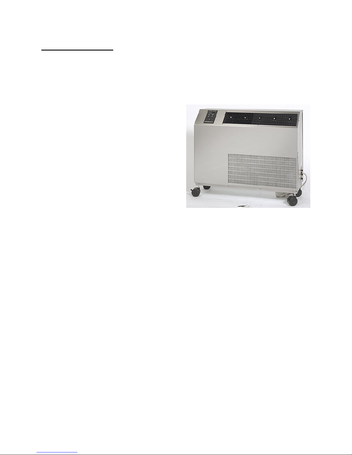
General Information
Koldwave 5WK Series Air Conditioners and
Heat Pumps are portable, water-cooled units
designed for applications where outside air
is not available and spot cooling is required.
The Koldwave air-conditioner cools an
entire area by discharging air through its
supply grille. Only power and condenser
water supply, water discharge, and
condensate drain piping are required for
installation.
The water-cooled condenser requires only
that amount of water needed to achieve the
desired high and low refrigeration system
pressures. The minimum condenser water
pressure for 85°F entering water temperature
can be found in the Specification and
Electrical Data section in this manual. A
refrigeration system head pressure actuated
water regulating valve regulates condenser
water.
Each unit is completely self-contained with
the entire refrigeration system, electrical
components, condenser and water valve
housed in one cabinet. All Koldwave units,
except the 5WK07, are provided with
heavy-duty casters. Two swivel-locking
casters prevent sliding; two stationary
casters provide handling ease for relocation.
The Koldwave 5WK07 is supplied with pads
on the bottom of the unit.
To attain the proper control of the water
flow rate entering the automatic water valve,
refer to the Specification and Electrical Data
Section to find the minimum water pressure
required for the condenser water supply.
The condenser water temperature leaving
the unit should not exceed 100°F. Ignoring
this compliance will void the warranty on
the refrigeration system. On heat pump
models it is not recommended to operate the
unit in the heating cycle when the water
temperature is below 50°F. Doing so could
reduce the specified heating capacity and
may cause the freeze control to cycle the
compressor off, resulting in a loss of
heating.
Model 5WK26
With the heat pump option the user can
manually select between the HEAT and
COOL functions using the touch pad control
panel or using the optional remote control.
4

Model Configuration
NOMENCLATURE
Example 5WK 14 B G A 1 A A A0
Code MD US R V C SS EC CC O
Field 1,2,3 4,5 6 7 8 9 10 11 12,13
1,2,3 – MODEL (MD)
5AK – Air Cooled Portable
5WK - Water Cooled Portable
4,5 – UNIT SIZE (US)
AK – Air Cooled Models
14 – 11,000 Btuh
18 – 18,300 Btuh
30 – 28,100 Btuh
39 – 36,800 Btuh
65 – 61,200 Btuh
WK - Water Cooled Portable
07 – 6,300 Btuh
14 – 10,800 Btuh
18 – 16,100 Btuh
23 – 23,000 Btuh
26 – 23,000 Btuh
36 – 34,700 Btuh
6 - REFRIGERANT (R)
A – R22
B – R410A
7 – VOLTAGE (V)
A – 208/3/60 (used only on 5WK65)
B – 230/3/60 (used only on 5WK65)
C – 460/3/60 (used only on 5WK65)
D – 575/3/60 (not used at this time)
E – 120/1/60
F – 208/1/60
G – 230/1/60
H – 100/1/50 (not used at this time)
J – 220/1/50 (not used at this time)
8 – CONFIGURATION (C)
A – Front Discharge with Adjustable Grilles
9 CONFIGURATION (SS)
1 – Stainless Steel
2 – Painted (5WK65 only)
10 – EVAPORATOR COIL (EC)
A – Standard Copper/Aluminum
E – Electrofin Coated
11 – CONDENSER COIL (CC)
A – Standard Copper/Aluminum
E – Electrofin Coated (Air Cooled Only)
N – Cupro-Nickel
12,13 – OPTIONS (O) WK Only
A0 – Standard Cooling
AP – Standard Cooling with High Lift Condensate Pump
AT – Standard Cooling for Cooling Tower Application (no water
valve)
AV – Standard Cooling for Cooling Tower Application with High
Lift Condensate Pump (no water valve)
H0 – Heat Pump
HP – Heat Pump with High Lift Condensate Pump
HT – Heat Pump for Cooling Tower Application (no water valve)
5
Installation Instructions
IMPORTANT: Following the installation
and preventative maintenance instructions
can extend the length of service you
receive from your Koldwave unit.
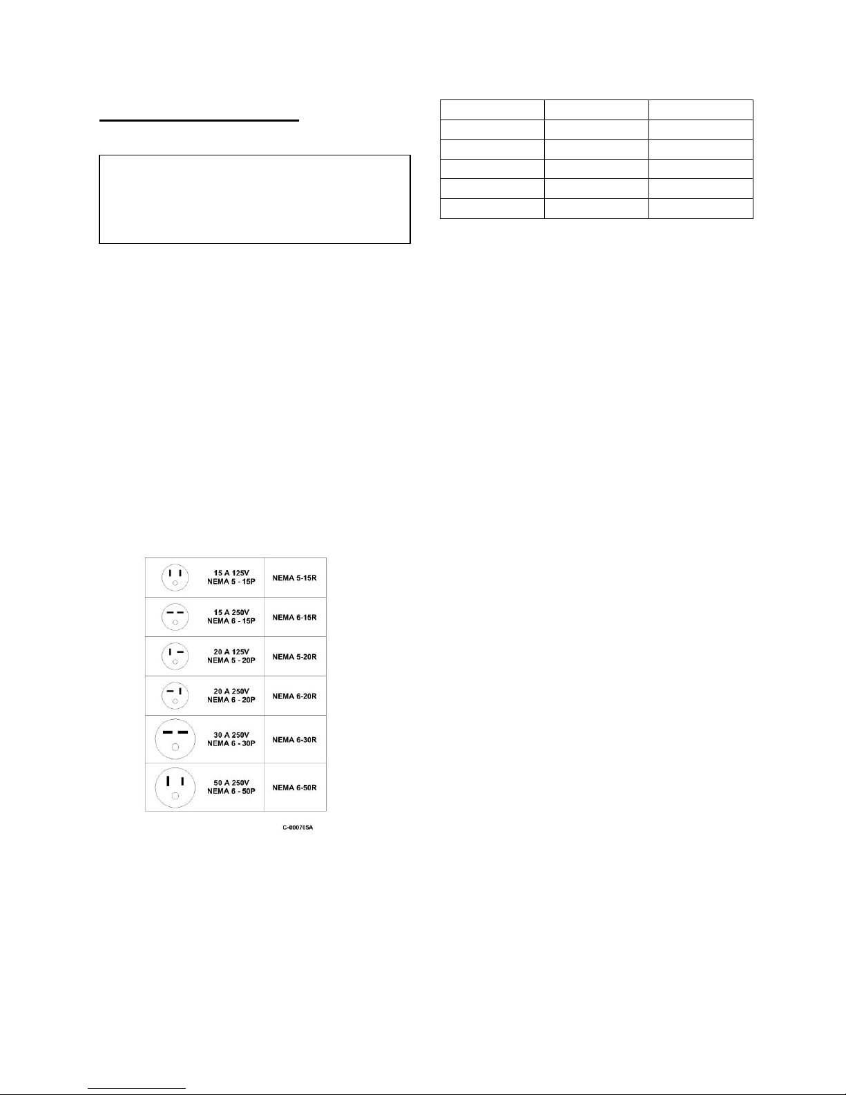
Electrical Requirements
Check the power supply to make certain it is
within 10% of the voltage listed on the data
plate located on the back of the unit.
Operating the unit on improper voltage
will void the product warranty.
Refer to the Rating Plate for voltage and
current information.
Each unit should have a dedicated circuit
breaker.
MODEL VOLTAGE PLUG TYPE
5WK07 120/1/60 5 – 15P
5WK14 120/1/60 5 – 15P
5WK18 208-230/1/60 6 – 20P
5WK23/26 208-230/1/60 6 – 20P
5WK36 208-230/1/60 6 – 20P
Some Koldwave units are equipped with
LCDI device service cords. The service
cords employed have plug configurations
and receptacle requirements as shown in the
chart above. Modifications to the cord will
void the product warranty.
Extension cords used with the Koldwave
units should match the plug configuration of
the service cord provided on the unit. The
extension cord must be equipped with an
equipment grounding conductor, grounding
type attachment plug, and a grounding type
attachment connector. The cord must also
have a rating suitable for the voltage and
ampacity.
Water Fitting Location
Prior to placing the air conditioner in the
desired position, note the exact location of
the water fittings on the valve plate on the
unit side panel.
Plug Types
6
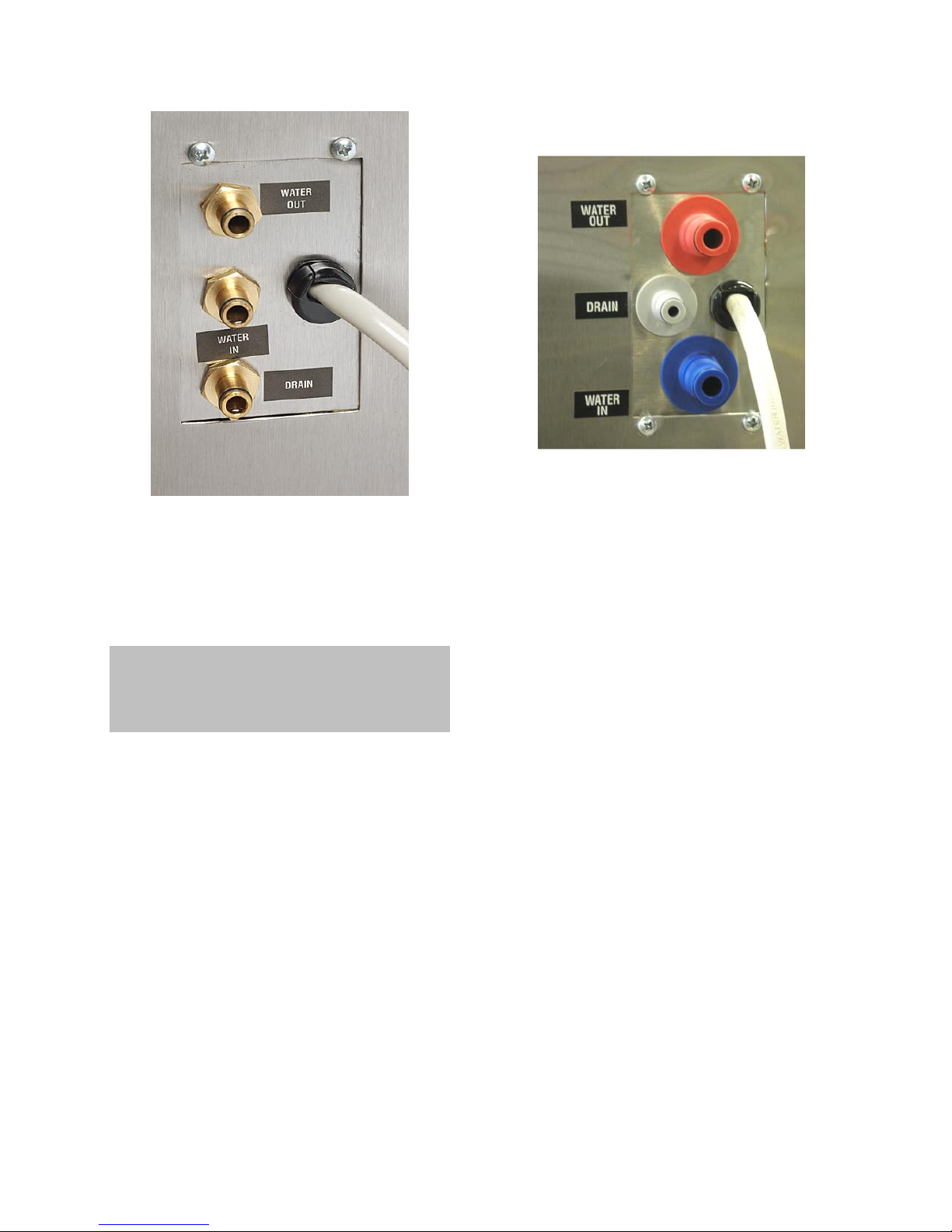
Figure A
Water lines should be securely attached to
the water valve plate fittings. This is easily
accomplished through the quick connect
hose kit provided with the unit.
Note: The water connections must be made
as shown in Figure A. The unit will not
operate properly if the connections are not in
the correct orientation.
7
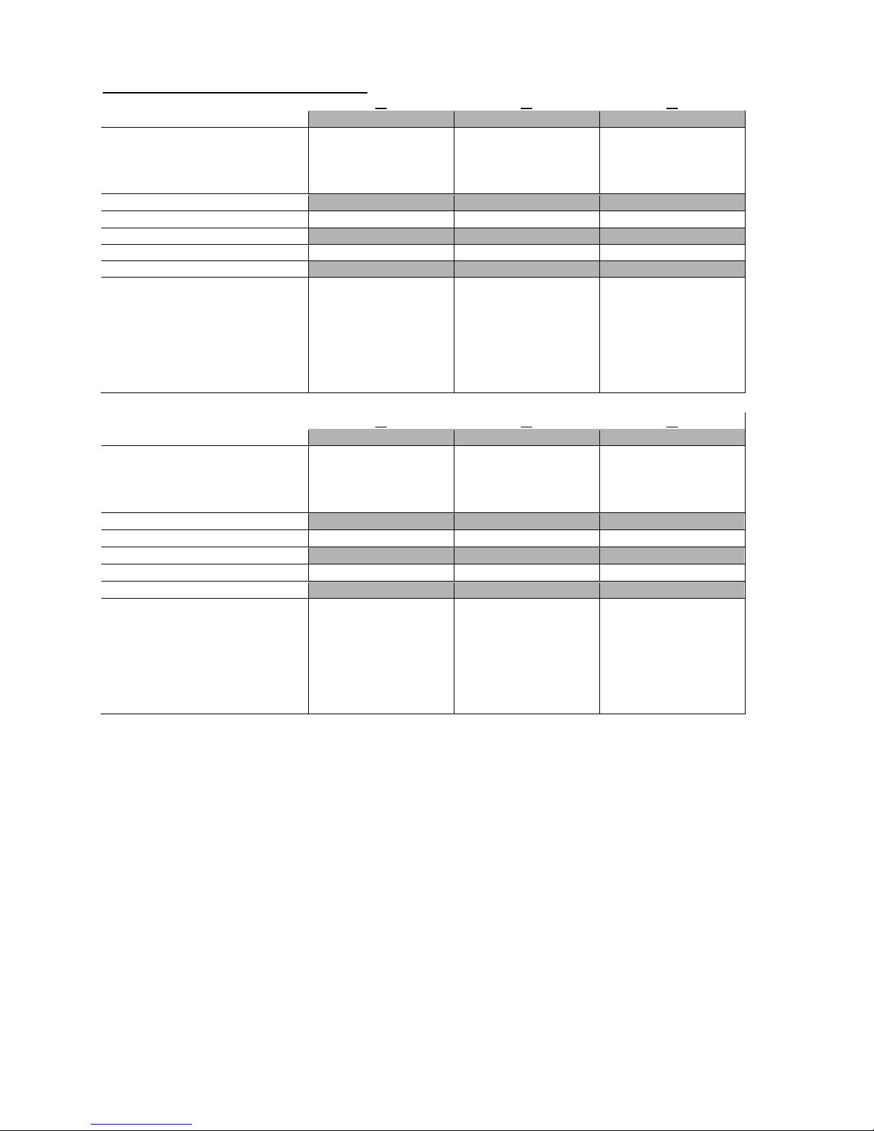
Specification and Electric Data
ELECTRIC DATA
Voltage/Phase/Hertz 115/1/60 115/1/60 230/1/60
Amperage 9.2 11.6 6.6
Fuse Size (Amps) 15 15 15
Watts 855 1107 1471
REFRIGERANT CHARGE
R410A (Ounces) 16 20 22
WATER SUPPLY
Minimum Water Pressure (PSI) 15 21 40.5
UNIT DIMENSIONS (INCHES)
Height with Casters 17.63 31.5 31.5
Height without Casters n/a 29.13 29.13
Width 22.38 25.00 25.00
Depth 12.00 10.19 10.19
Evaporator Filter (qty) (1) 15.75 x 9.13 x 0.5 (1) 15.88 x 18 x 0.5 (1) 24 x 11.75 x 0.5
NET UNIT WEIGHT (LBS.)
SHIPPING WEIGHT (LBS.)
ELECTRIC DATA
Voltage/Phase/Hertz 230/1/60 230/1/60 230/1/60
Amperage 10 10 14.2
Fuse Size (Amps) 15 15 20
Watts 2189 2189 2994
REFRIGERANT CHARGE
R410A (Ounces) 39 39 42
WATER SUPPLY
Minimum Water Pressure (PSI) 55.8 55.8 47.8
UNIT DIMENSIONS (INCHES)
Height with Casters 28.75 28.75 33.25
Height without Casters 26.38 26.38 28.5
Width 36 36 43.5
Depth 12.25 12.25 15.38
Evaporator Filter (qty) (1) 24 x 11.75 x 0.5 (1) 24 x 11.75 x 0.5 (1) 13.25 x 31.5 x 0.5
NET UNIT WEIGHT (LBS.)
SHIPPING WEIGHT (LBS.)
Time delay fuses and circuit breakers are recommended.
*** Electrical ratings based on 80/67 indoor air and 85e/95l water side conditions on high speed.
14 18
07
*** *** ***
83 122 125
89 131 134
26 36
23
*** *** ***
183 183 245
201 201 253
8
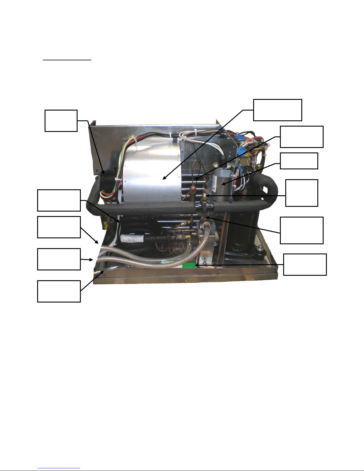
Serviceability
The Koldwave unit has removable panels to provide full service accessibility.
5WK07 Unit Construction Back View
Blower
Motor
Condenser
Coil
Blower Wheel
Housing
Evaporator
Coil
Capacitor
Suction
Service
Access
Condenser
Water Outlet
Condenser
Water Inlet
Condenser
Drain Outlet
Water
Regulating
Valve
Condensate
Pump
9

ccumulator
5WK07 Unit Construction Side View
Discharge
Service
Access
Compressor
Contactor
Transformer
Hard Start
Assembly
A
Compressor
10
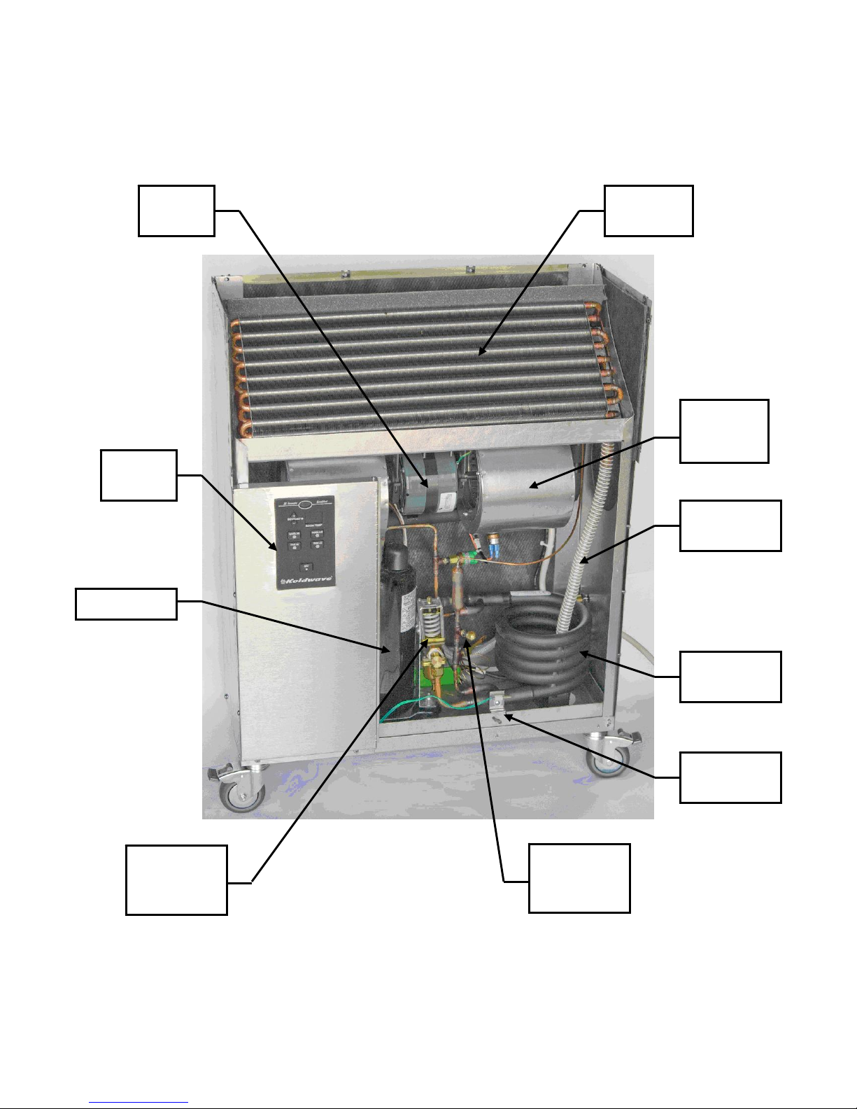
5WK14 Unit Construction Front View
Blower
Motor
Control
Panel
Evaporator
Coil
Blower
Wheel
Housing
Compressor
Water
Regulating
Valve
Condensate
Drain Tube
Condenser
Coil
Temperature
Sensor
Discharge
Service
Access
11
 Loading...