

IOM5WK-1
Koldwave 5WK Installation, Operation, & Maintenance Manual
ATTENTION: READ THIS MANUAL AND ALL LABELS ATTACHED TO THE UNIT
CAREFULY BEFORE ATTEMPTING TO INSTALL, OPERATE OR SERVICE
THESE UNITS. CHECK DATA PLATES FOR ELECTRICAL SPECIFICATIONS
AND MAKE CERTAIN THAT THESE AGREE WITH THOSE AT THE POINT OF
INSTALLATION. RECORD THE UNIT MODEL AND SERIAL NUMBER IN THE
SPACE PROVIDED. RETAIN THIS DOCUMENT FOR FUTURE REFERENCE.
Model No._______________________ Serial No._______________________________
IMPROPER INSTALLATION, ADJUSTMENT, ALTERATION, SERVICE OR
MAINTENANCE CAN CAUSE PROPERTY DAMAGE, INJURY OR DEATH. THIS
APPLIANCE MUST BE INSTALLED BY A LICENSED CONTRACTOR OR
QUALIFIED SERVICE PERSONNEL. READ THESE INSTALLATION, OPERATING
AND MAINTENANCE INSTRUCTIONS THOROUGHLY BEFORE INSTALLING OR
SERVICING THE UNIT.
WARNING: INSTALL, OPERATE AND MAINTAIN UNIT IN ACCORDANCE WITH
MANUFACTURER’S INSTRUCTIONS TO AVOID ANY DETERING FACTORS
THAT MAY CAUSE PERSONAL INJURY OR PROPERTY DAMAGE.
INSTALLER’S RESPONSIBILITY: THIS EQUIPMENT HAS BEEN RUN TESTED
AND INSPECTED THOROUGHLY. IT HAS BEEN SHIPPED FREE FROM
DEFECTS FROM OUR FACTORY. HOWEVER, DURING SHIPMENT AND
INSTALLATION, PROBLEMS SUCH AS LOOSE WIRES, LEAKS, OR LOOSE
FASTENERS MAY OCCUR. IT IS THE INSTALLER’S RESPONSIBILITY TO
INSPECT AND CORRECT ANY PROBLEMS THAT MAY BE FOUND.
1

IOM5WK-1
Table of Contents:
GENERAL INFORMATION ...................................................................................................... 4
MODEL CONFIGURATION...................................................................................................... 5
INSTALLATION INSTRUCTIONS .......................................................................................... 6
ELECTRICAL REQUIREMENTS ....................................................................................................... 6
WATER FITTING LOCATION ......................................................................................................... 6
SPECIFICATION AND ELECTRIC DATA ............................................................................. 8
SERVICEABILITY ...................................................................................................................... 9
5WK07 UNIT CONSTRUCTION BACK VIEW ................................................................................. 9
5WK07 UNIT CONSTRUCTION SIDE VIEW ................................................................................. 10
5WK14 UNIT CONSTRUCTION FRONT VIEW .............................................................................. 11
5WK14
5WK14
5WK18 UNIT CONSTRUCTION BACK VIEW ............................................................................... 14
5WK18 UNIT CONSTRUCTION SIDE VIEW ................................................................................. 15
5WK23/26 UNIT CONSTRUCTION BACK VIEW .......................................................................... 16
5WK23/26 UNIT CONSTRUCTION LEFT VIEW ........................................................................... 17
5WK36 UNIT CONSTRUCTION BACK VIEW ............................................................................... 18
5WK36 UNIT CONSTRUCTION LEFT VIEW ................................................................................. 19
HEAT PUMP UNIT CONSTRUCTION FRONT VIEW .......................................................... 12
HEAT PUMP UNIT CONSTRUCTION BACK VIEW ............................................................ 13
UNIT OPERATION ................................................................................................................... 20
UNIT POWER ON: ....................................................................................................................... 20
FAN HI: ...................................................................................................................................... 20
FAN LO: ..................................................................................................................................... 20
COOLING HI: .............................................................................................................................. 20
COOLING LO: ............................................................................................................................. 20
HEATING HI (HEAT PUMP UNIT): ............................................................................................... 20
HEATING LO (HEAT PUMP UNIT): .............................................................................................. 20
EMPERATURE SETTING: ........................................................................................................... 20
T
UNIT OFF: .................................................................................................................................. 20
O
THER SETTINGS: ...................................................................................................................... 20
OMPRESSOR OFF TIME: ............................................................................................................ 21
C
SELF RECOVERY MODE (*): ....................................................................................................... 21
CHECK ALARMS: ........................................................................................................................ 21
OPTIONAL REMOTE CONTROL: .................................................................................................. 21
INSPECTION AND REPAIR OF ELECTRICAL SYSTEM ................................................ 23
C
OMPRESSOR AND FAN MOTOR CAPACITORS ............................................................................ 23
INSPECTION AND REPAIR OF REFRIGERANT SYSTEM ............................................. 23
PREVENTATIVE MAINTENANCE ....................................................................................... 23
NIT STORAGE .......................................................................................................................... 24
U
ELECTRICAL DIAGRAM ....................................................................................................... 25
2

IOM5WK-1
5WK07, 5WK14 115V/1 PH ..................................................................................................... 25
5WK18, 5WK23, 5WK26 208-230V 1 PH ............................................................................... 26
5WK36 208-230V/1PH ............................................................................................................. 27
TROUBLE SHOOTING GUIDE .............................................................................................. 28
TROUBLE SHOOTING GUIDE CONTINUED ..................................................................... 29
TROUBLE SHOOTING GUIDE CONTINUED ..................................................................... 30
TROUBLE SHOOTING GUIDE CONTINUED ..................................................................... 31
TROUBLE SHOOTING GUIDE CONTINUED ..................................................................... 32
TROUBLE SHOOTING GUIDE CONTINUED ..................................................................... 33
3
General Information
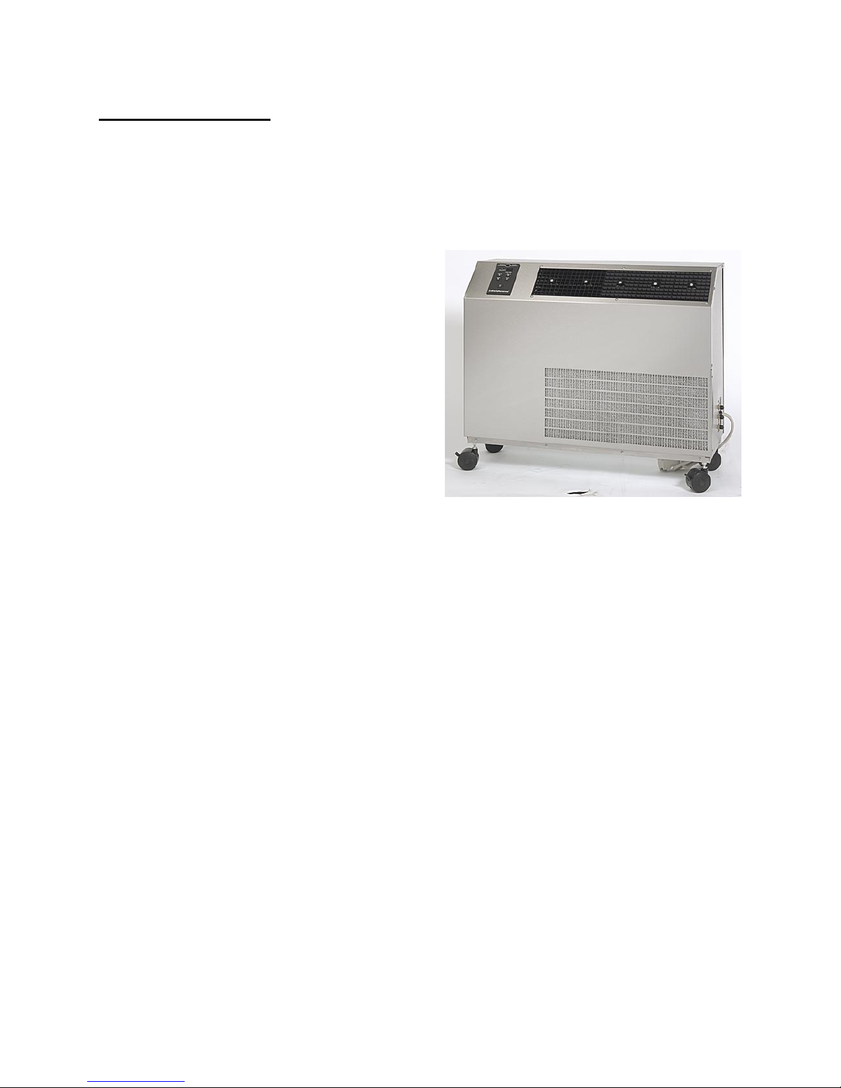
Koldwave 5WK Series Air Conditioners and
Heat Pumps are portable, water-cooled units
designed for applications where outside air
is not available and spot cooling is required.
The Koldwave air-conditioner cools an
entire area by discharging air through its
supply grille. Only power and condenser
water supply, water discharge, and
condensate drain piping are required for
installation.
The water-cooled condenser requires only
that amount of water needed to achieve the
desired high and low refrigeration system
pressures. The minimum condenser water
pressure for 85°F entering water temperature
can be found in the Specification and
Electrical Data section in this manual. A
refrigeration system head pressure actuated
water regulating valve regulates condenser
water.
Each unit is completely self-contained with
the entire refrigeration system, electrical
components, condenser and water valve
housed in one cabinet. All Koldwave units,
except the 5WK07, are provided with
heavy-duty casters. Two swivel-locking
casters prevent sliding; two stationary
casters provide handling ease for relocation.
The Koldwave 5WK07 is supplied with pads
on the bottom of the unit.
To attain the proper control of the water
flow rate entering the automatic water valve,
refer to the Specification and Electrical Data
Section to find the minimum water pressure
required for the condenser water supply.
The condenser water temperature leaving
the unit should not exceed 100°F. Ignoring
this compliance will void the warranty on
the refrigeration system. On heat pump
models it is not recommended to operate the
unit in the heating cycle when the water
temperature is below 50°F. Doing so could
reduce the specified heating capacity and
may cause the freeze control to cycle the
compressor off, resulting in a loss of
heating.
Model 5WK26
With the heat pump option the user can
manually select between the HEAT and
COOL functions using the touch pad control
panel or using the optional remote control.
4
Model Configuration
NOMENCLATURE
Example 5WK 14 B G A 1 A A A0
Code MD US R V C SS EC CC O
Field 1,2,3 4,5 6 7 8 9 10 11 12,13
1,2,3 – MODEL (MD)
5AK – Air Cooled Portable
5WK - Water Cooled Portable
4,5 – UNIT SIZE (US)
AK – Air Cooled Models
14 – 11,000 Btuh
18 – 18,300 Btuh
30 – 28,100 Btuh
39 – 36,800 Btuh
65 – 61,200 Btuh
WK - Water Cooled Portable
07 – 6,300 Btuh
14 – 10,800 Btuh
18 – 16,100 Btuh
23 – 23,000 Btuh
26 – 23,000 Btuh
36 – 34,700 Btuh
6 - REFRIGERANT (R)
A – R22
B – R410A
7 – VOLTAGE (V)
A – 208/3/60 (used only on 5WK65)
B – 230/3/60 (used only on 5WK65)
C – 460/3/60 (used only on 5WK65)
D – 575/3/60 (not used at this time)
E – 120/1/60
F – 208/1/60
G – 230/1/60
H – 100/1/50 (not used at this time)
J – 220/1/50 (not used at this time)
8 – CONFIGURATION (C)
A – Front Discharge with Adjustable Grilles
9 CONFIGURATION (SS)
1 – Stainless Steel
2 – Painted (5WK65 only)
10 – EVAPORATOR COIL (EC)
A – Standard Copper/Aluminum
E – Electrofin Coated
11 – CONDENSER COIL (CC)
A – Standard Copper/Aluminum
E – Electrofin Coated (Air Cooled Only)
N – Cupro-Nickel
12,13 – OPTIONS (O) WK Only
A0 – Standard Cooling
AP – Standard Cooling with High Lift Condensate Pump
AT – Standard Cooling for Cooling Tower Application (no water
valve)
AV – Standard Cooling for Cooling Tower Application with High
Lift Condensate Pump (no water valve)
H0 – Heat Pump
HP – Heat Pump with High Lift Condensate Pump
HT – Heat Pump for Cooling Tower Application (no water valve)
5
Installation Instructions
IMPORTANT: Following the installation
and preventative maintenance instructions
can extend the length of service you
receive from your Koldwave unit.
Electrical Requirements
Check the power supply to make certain it is
within 10% of the voltage listed on the data
plate located on the back of the unit.
Operating the unit on improper voltage
will void the product warranty.
Refer to the Rating Plate for voltage and
current information.
Each unit should have a dedicated circuit
breaker.
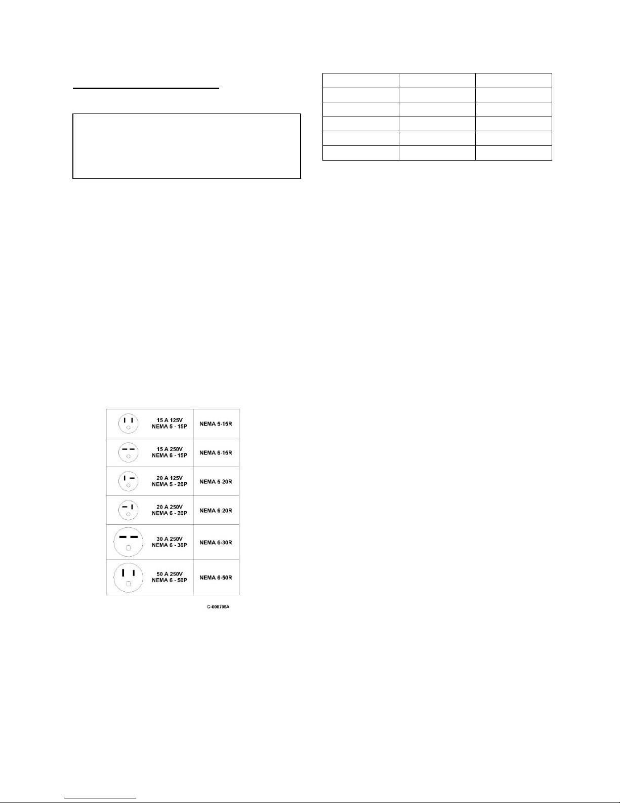
MODEL VOLTAGE PLUG TYPE
5WK07 120/1/60 5 – 15P
5WK14 120/1/60 5 – 15P
5WK18 208-230/1/60 6 – 20P
5WK23/26 208-230/1/60 6 – 20P
5WK36 208-230/1/60 6 – 20P
Some Koldwave units are equipped with
LCDI device service cords. The service
cords employed have plug configurations
and receptacle requirements as shown in the
chart above. Modifications to the cord will
void the product warranty.
Extension cords used with the Koldwave
units should match the plug configuration of
the service cord provided on the unit. The
extension cord must be equipped with an
equipment grounding conductor, grounding
type attachment plug, and a grounding type
attachment connector. The cord must also
have a rating suitable for the voltage and
ampacity.
Water Fitting Location
Prior to placing the air conditioner in the
desired position, note the exact location of
the water fittings on the valve plate on the
unit side panel.
Plug Types
6
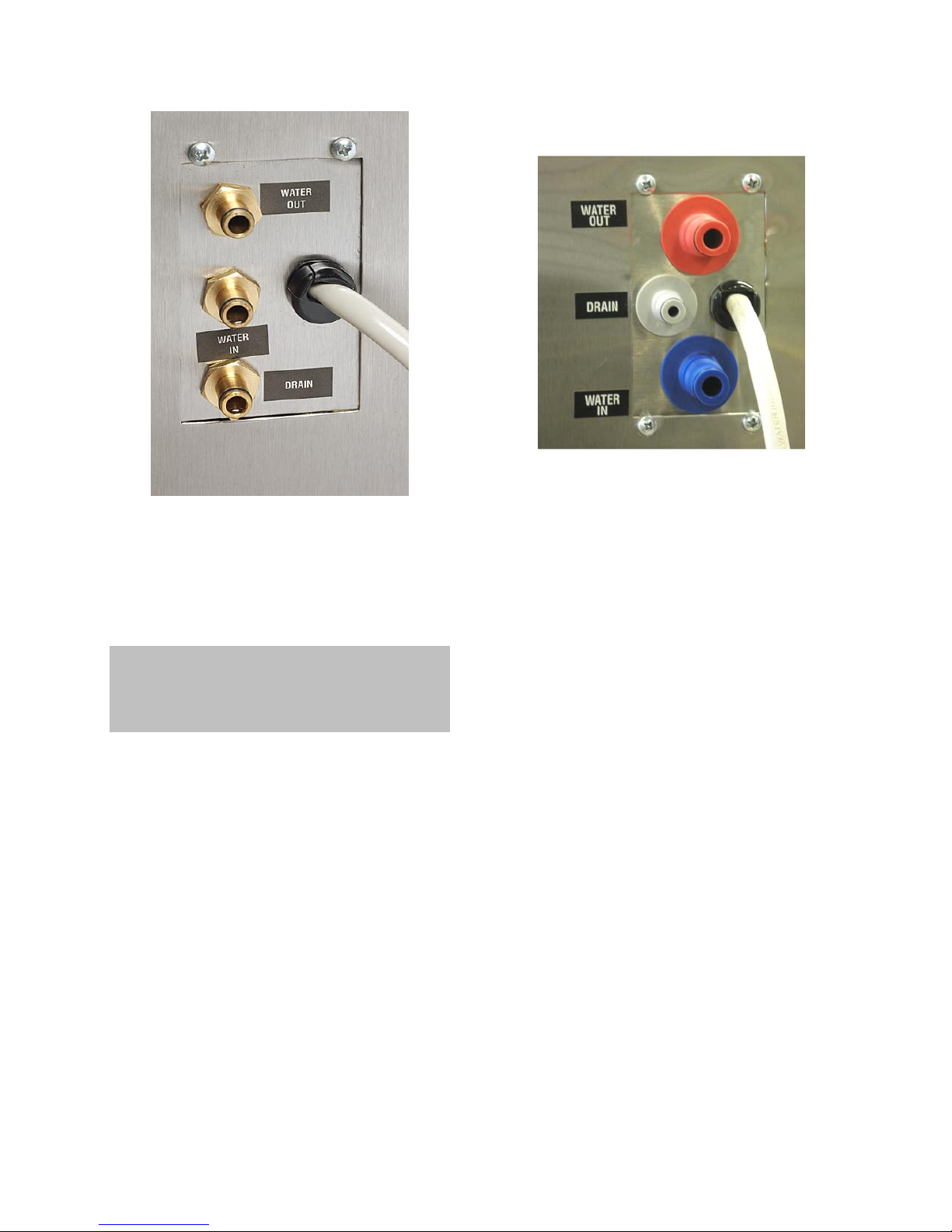
Figure A
Water lines should be securely attached to
the water valve plate fittings. This is easily
accomplished through the quick connect
hose kit provided with the unit.
Note: The water connections must be made
as shown in Figure A. The unit will not
operate properly if the connections are not in
the correct orientation.
7
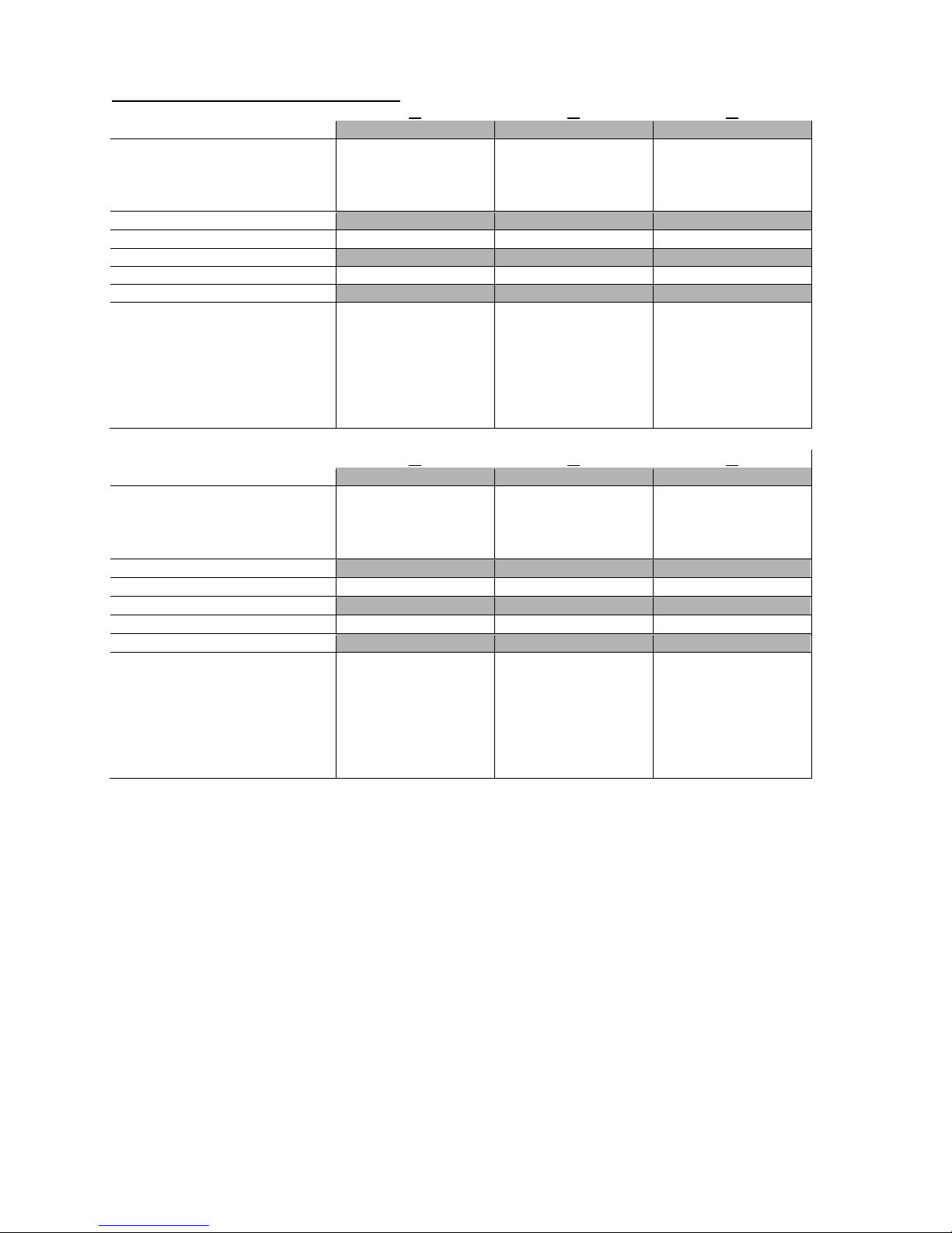
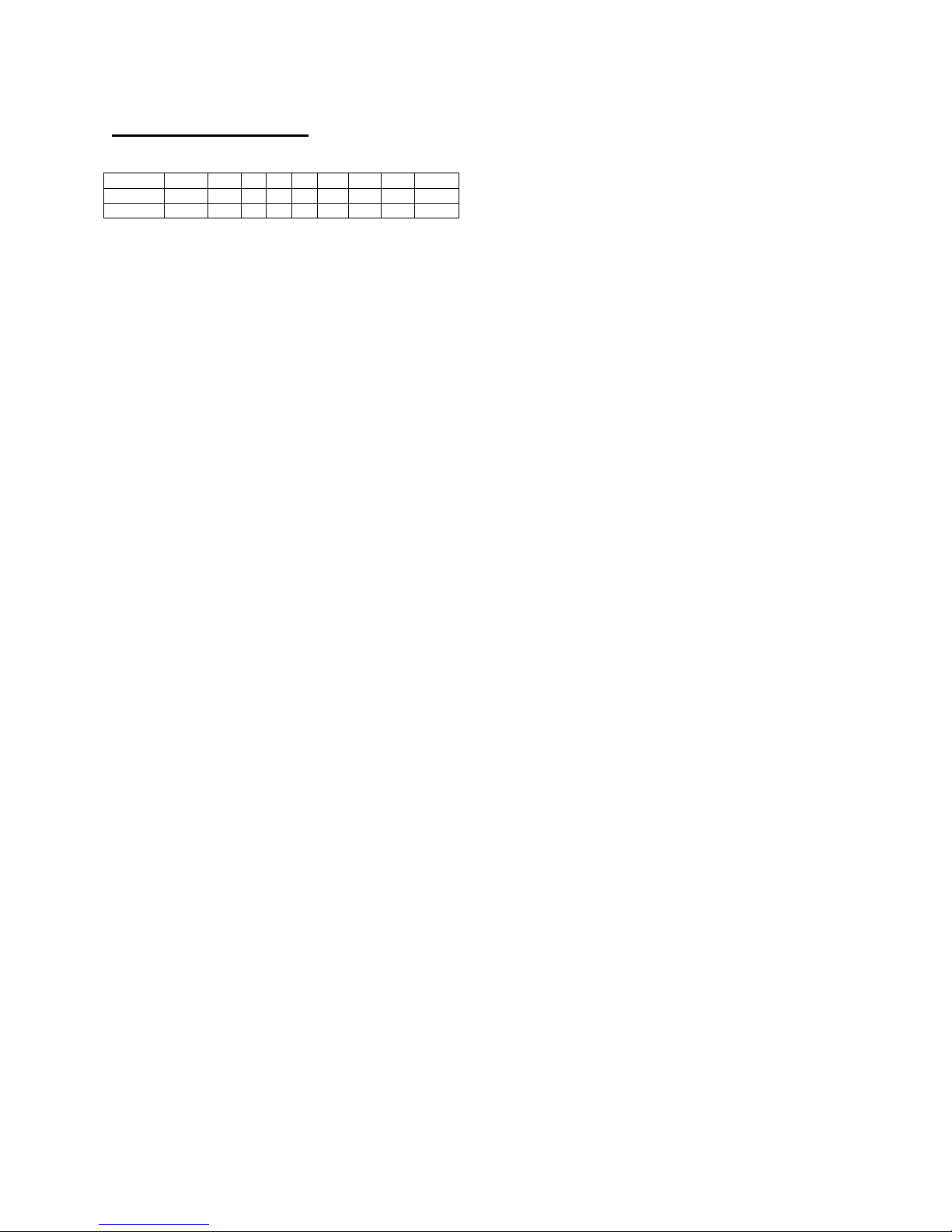
Specification and Electric Data
ELECTRIC DATA
Voltage/Phase/Hertz 115/1/60 115/1/60 230/1/60
Amperage 9.2 11.6 6.6
Fuse Size (Amps) 15 15 15
Watts 855 1107 1471
REFRIGERANT CHARGE
R410A (Ounces) 16 20 22
WATER SUPPLY
Minimum Water Pressure (PSI) 15 21 40.5
UNIT DIMENSIONS (INCHES)
Height with Casters 17.63 31.5 31.5
Height without Casters n/a 29.13 29.13
Width 22.38 25.00 25.00
Depth 12.00 10.19 10.19
Evaporator Filter (qty) (1) 15.75 x 9.13 x 0.5 (1) 15.88 x 18 x 0.5 (1) 24 x 11.75 x 0.5
NET UNIT WEIGHT (LBS.)
SHIPPING WEIGHT (LBS.)
ELECTRIC DATA
Voltage/Phase/Hertz 230/1/60 230/1/60 230/1/60
Amperage 10 10 14.2
Fuse Size (Amps) 15 15 20
Watts 2189 2189 2994
REFRIGERANT CHARGE
R410A (Ounces) 39 39 42
WATER SUPPLY
Minimum Water Pressure (PSI) 55.8 55.8 47.8
UNIT DIMENSIONS (INCHES)
Height with Casters 28.75 28.75 33.25
Height without Casters 26.38 26.38 28.5
Width 36 36 43.5
Depth 12.25 12.25 15.38
Evaporator Filter (qty) (1) 24 x 11.75 x 0.5 (1) 24 x 11.75 x 0.5 (1) 13.25 x 31.5 x 0.5
NET UNIT WEIGHT (LBS.)
SHIPPING WEIGHT (LBS.)
Time delay fuses and circuit breakers are recommended.
*** Electrical ratings based on 80/67 indoor air and 85e/95l water side conditions on high speed.
14 18
07
*** *** ***
83 122 125
89 131 134
26 36
23
*** *** ***
183 183 245
201 201 253
8
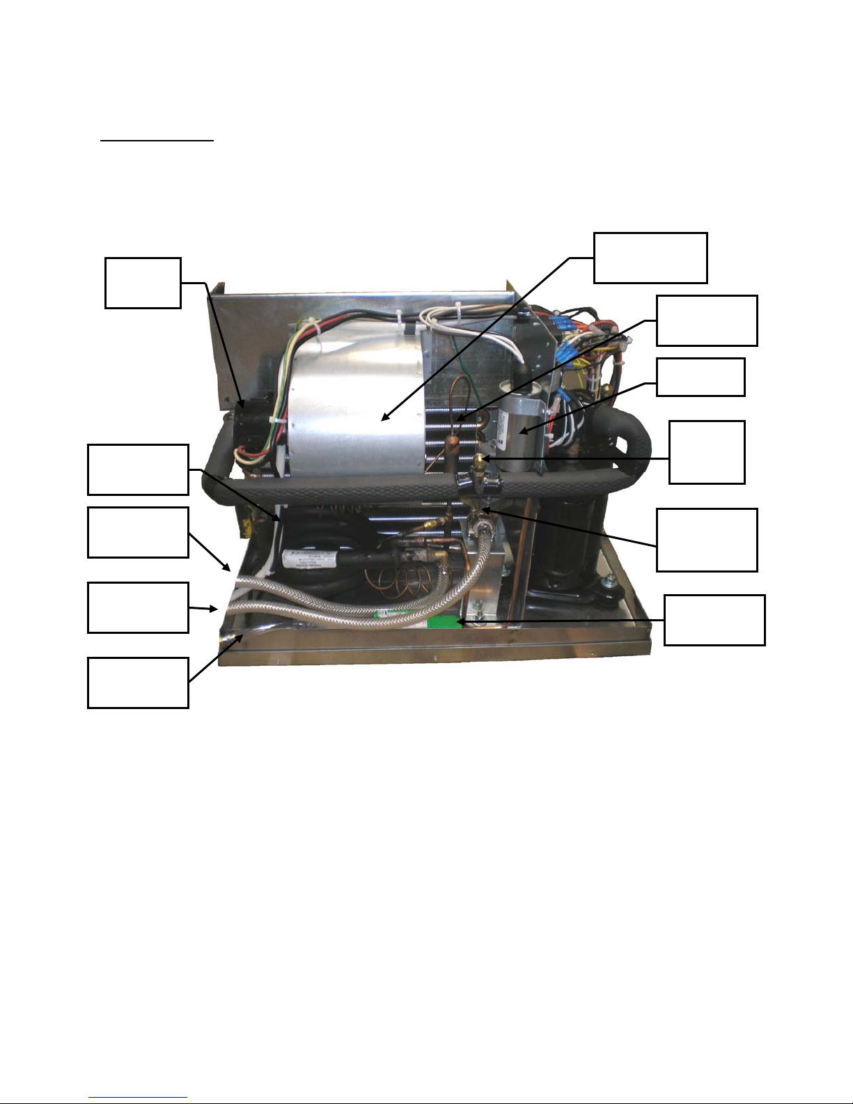
Serviceability
The Koldwave unit has removable panels to provide full service accessibility.
5WK07 Unit Construction Back View
Blower
Motor
Condenser
Coil
Blower Wheel
Housing
Evaporator
Coil
Capacitor
Suction
Service
Access
Condenser
Water Outlet
Condenser
Water Inlet
Condenser
Drain Outlet
Water
Regulating
Valve
Condensate
Pump
9

ccumulator
5WK07 Unit Construction Side View
Discharge
Service
Access
Compressor
Contactor
Transformer
Hard Start
Assembly
A
Compressor
10
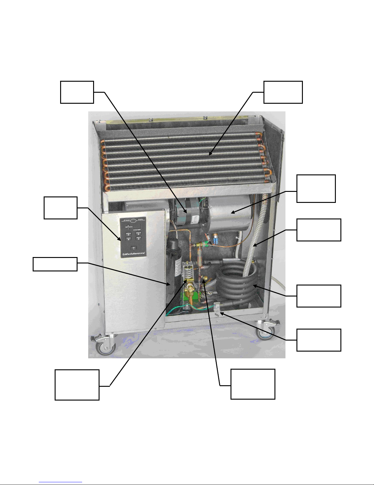
5WK14 Unit Construction Front View
Blower
Motor
Control
Panel
Evaporator
Coil
Blower
Wheel
Housing
Compressor
Water
Regulating
Valve
Condensate
Drain Tube
Condenser
Coil
Temperature
Sensor
Discharge
Service
Access
11

ccumulator
Strainer
5WK14 Heat Pump Unit Construction Front View
Discharge
Service
Access
Water Bypass
Valve
Reversing
Valve
A
Condenser
Coil
Regulating
Valve
Water
12

5WK14 Heat Pump Unit Construction Back View
Reversing
Valve
Water Bypass
Valve
Discharge
Service
Access
Condensate
Pump
Compressor
13

5WK18 Unit Construction Back View
Blower
Motor
Blower
Wheel
Housing
Discharge
Service
Access
Suction
Service
Access
Condenser
Coil
Evaporator
Coil
Compressor &
Accumulator
Water
Regulating
Valve
14

ccumu
5WK18 Unit Construction Side View
Capacitor
Suction
Service
Access
Hard Start
Assembly
Compressor
Relay
Discharge
Service
Access
A
Compressor
lator
15

5WK23/26 Unit Construction Back View
Blower
Motor
Blower
Wheel
Housing
Condenser
Coil
Evaporator
Coil
Compressor &
Accumulator
Water
Regulating
Valve
16

ccumulat
or
5WK23/26 Unit Construction Left View
Transformer
Hard Start
Assembly
Discharge
Service
Access
Reversing
Valve
Suction
Service
Access
Condensate
Pump
Compressor
A
17

5WK36 Unit Construction Back View
Blower
Motor
Capacitor
Blower
Motor
Blower
Wheel
Housing
Compressor
Condenser
Coil
Evaporator
Coil
Water
Regulating
Valve
18

Contactor
5WK36 Unit Construction Left View
Transformer
Potential
Relay
Run
Capacitor
Discharge
Service
Access
Suction
Service
Access
Start
Capacitor
Compressor
Reversing
Valve
19

Unit Operation
Unit Power On:
Plug in the unit to the power source. The
LED display will show the current controller
version number for 0.5 seconds. Then, the
LED temperature indicator will illuminate
the set point for 5 seconds and then switch
to the room temperature reading. The Power
RED LED will illuminate. By depressing
any mode button, the Power LED will turn
off.
Fan Hi:
Depress the FAN HIGH button, the unit will
be in fan mode and the evaporator fan
blower will operate at High Speed. The
GREEN LED will illuminate accordingly.
Fan Lo:
Depress the FAN LOW button, the unit will
be in fan mode and the evaporator fan
blower will operate at Low Speed. The
GREEN LED will illuminate accordingly.
Cooling Hi:
Depress the COOL HIGH button, the unit
will be in cooling mode depending on
thermostat reading. The compressor will
turn on based on the thermostat reading and
the Compressor Off Time setting. The
evaporator fan blower will operate at High
Speed. The BLUE LED will illuminate
accordingly.
Cooling Lo:
Depress the COOL HIGH button, the unit
will be in cooling mode depending on
thermostat reading. The compressor will
turn on based on the thermostat reading and
the Compressor Off Time setting. The
evaporator fan blower will operate at Low
Speed. The BLUE LED will illuminate
accordingly.
Heating Hi (Heat Pump Unit):
Depress the HEAT HIGH button; the unit
will be in the heating mode depending on
the thermostat reading. The reversing valve
will operate to prompt the heat pump mode.
The compressor will turn on based on the
thermostat reading and the Compressor Off
Time setting. The evaporator fan blower
will operate at High Speed. The AMBER
LED will illuminate accordingly.
Heating Lo (Heat Pump Unit):
Depress the HEAT LOW button; the unit
will be in the heating mode depending on
the thermostat reading. The reversing valve
will operate to prompt the heat pump mode.
The compressor will turn on based on the
thermostat reading and the Compressor Off
Time setting. The evaporator fan blower
will operate at Low Speed. The AMBER
LED will illuminate accordingly.
Temperature Setting:
During any mode of operation, the user is
able to change the set point by depressing
the arrow buttons. The temperature
indicator will switch to display “set point
temperature”. Depressing the ARROW UP
or ARROW DOWN button will change the
set point. The SETPOINT LED will
illuminate. The temperature indicator will
switch back to display “room temperature”
after 5 seconds.
Unit Off:
Depress the OFF button at any time to turn
the SYSTEM MODE off. The unit will
remain idle until further instruction. The
Power RED LED will illuminate.
Other Settings:
During the cooling mode, the compressor
will only be energized if the temperature is
at least 2 degrees above the set point, and
de-energized once the temperature falls to 2
degrees below the set point. During the
20

heating mode, the compressor will only be
energized if the temperature is at least 2
degrees below the set point, and deenergized once the temperature rises 2
degrees above the set point. User is able to
manually change the temperature differential
(default set at 2) by depressing both UP and
DOWN arrow key and then adjust UP and
DOWN arrow to set the differential from 14 degrees. After 3 seconds, it will return to
the room temperature reading.
Compressor Off Time:
The compressor routine guarantees a 5minute minimum off time on the
compressor, and it will not energize until the
5-minute off time has been satisfy.
Self Recovery Mode (*):
The unit controller is shipped with selfrecovery mode activated so that with any
sudden power interruption, the set point and
operating mode are stored in memory and
the unit will retain these settings and resume
operation once power is restored. When the
self-recovery mode is enabled the decimal
point on the second character on the LED
display is always On. If self-recovery mode
is not enabled then the second decimal point
is always Off. However, the user is able to
enable the “Self Recovery Mode” by
depressing the OFF button for 5 seconds and
then adjust the setting from the arrow key.
A0 – Self Recovery Mode “off”
A1 – Self Recovery Mode “on” (Factory
Default Setting)
Check Alarms:
The controller will monitor and check the
status of two alarm signals:
1. Alarm_Tank_Full (E.F),
2. Alarm_Temperature_Sensor (E.S).
When E.F, or E.S alarm is present, the
Power LED will blink, signaling that the
alarm condition is present, and the unit will
lock out. Once the failure is cleared, press
the OFF button, the Power LED will stop
blinking, and the room temperature will
display.
Optional Remote Control:
The optional remote control has identical
functions as the main unit excluding the
following:
1. Ability to change the “temperature
differential” setting. User can only
adjust such setting through the main
unit panel.
2. Ability to enable or disable the “self
recovery mode” setting. User can
only adjust such setting through the
main unit panel.
* User is only allowed to change setting
when unit is OFF*
21

AC Unit Control Panel
Heat Pump Unit Control Panel
Optional Remote Control
22

Inspection and Repair of Electrical
System
* Koldwave Technical Services
Department must be contacted prior
to or during any repair/service on a
unit which is under warranty.
Service other than routine
maintenance should be performed
only by a qualified refrigeration
service person.
Always disconnect power and discharge
capacitors before servicing.
Compressor and Fan Motor Capacitors
Visually check the capacitors for bulges or
signs of leakage. Using a capacitor tester,
check each capacitor shorts, grounds, or
leakage. Also verify the capacitance in mfd
matches the capacitor rating.
Inspection and Repair of
Refrigerant System
* Koldwave Technical Services
Department must be contacted prior
to or during any repair/service on a
unit which is under warranty.
Service other than routine
maintenance should be performed
only by a qualified refrigeration
service person.
Check all connections and every part for
leaks whenever the refrigerant system is
repaired. Use a leak detector, soap solution,
or a halide torch to inspect the system.
When repairing a refrigerant leak, the
brazing flame will cause oxidation to occur
inside the copper tubing being repaired. It is
therefore desirable to use a slightly reduced
flame and to flow dry nitrogen gas through
the refrigerant piping while brazing to
prevent this oxidation from taking place.
Once the repair is completed, thoroughly
evacuate the refrigerant system with a
vacuum pump before recharging the system.
Koldwave strongly recommends a
filter/dryer be installed when any repairs are
made to the refrigeration system.
Preventative Maintenance
Your Koldwave portable spot cooler has
been designed to give maximum
performance and reliability with minimum
maintenance. Maintenance of the system is
concentrated in three areas covered in the
following paragraphs.
Blower Motors
Caution: Always disconnect the power
source before working on or near a motor
or its connected load.
The motor may require periodic cleaning to
prevent the possibility of overheating due to
an accumulation of dust and dirt on the
windings or on the motor exterior.
Filter
The life of a filter depends entirely on its
environment and use. It is recommended
that air filters be inspected on a regular basis
every four to six weeks. A clogged filter
will cause the unit to operate at greatly
reduced efficiency. This unit employs one
1/2" thick, washable aluminum mesh air
filter located behind the louvered front
(evaporator) panel. The evaporator filter can
easily be removed and cleaned; pull down
the evaporator intake hinged door and pull
the filter out. The filters must be washed
periodically when needed. This may be done
23

as follows:
1. Soak filter in solution of warm water and
detergent for 15 minutes.
2. Rinse in clean, hot water and shake excess
moisture from filter.
3. Spray one side of filter with light film of
oil.
4. Reinstall with oiled surface facing out
from unit.
Coils and Related Items
Coil Maintenance
The evaporator coil surfaces must be kept
clean of dirt and lint in order to operate at
rated efficiency. The coil should be
inspected on a regular basis and cleaned as
required.
CAUTION: Solutions used to clean coils
must not be corrosive to metals or
materials used in the manufacture of this
equipment. Take care to not damage the
coil or fins if using a high pressure spray
to apply the cleaning solutions.
Condensate Pump
Caution: Always disconnect the power
source before working on or near the
pump.
Pump Maintenance:
Do not touch or clean the sensor device with
sharp objects or tools. The sensor element is
fragile so handle with care. Replace the
pump if damaged in any way. If servicing,
clean carefully with a soft brush, cloth, or
under a slow running tap. Rinse out the tray
thoroughly.
Do not use solvent based cleaning agents.
Only mild detergents may be used, but rinse
thoroughly before refitting.
Do not use if the pump or its cable is
damaged in any way. Protect the cable and
tubing from sharp edges.
The condensate drain pan should be
periodically flushed.
Unit Storage
CAUTION:
If the unit is to be stored in an
unconditioned space where it will be
exposed to freezing temperatures, all
water must be removed from the
condenser coil prior to storage. Use 15 –
20 PSI of compressed air or nitrogen
applied to the Water In (middle)
connection. To do this turn the unit off.
Shut off the water supply. Disconnect the
3 hose manifold (Water Out, Water In,
Drain) from the unit. Place the unit in the
Cooling mode. Once the compressor
starts and runs for 15 seconds,
blow any remaining water out of the
condenser coil.
24

Electrical Diagram
5WK07, 5WK14 115V/1 PH
25

5WK18, 5WK23, 5WK26 208-230V 1 PH
26

5WK36 208-230V/1PH
27

Trouble Shooting Guide
Before troubleshooting this system, read this manual to determine electrical power and
installation requirements to allow the spot cooler to perform at its maximum efficiency. Refer to
general description, wiring diagrams and photographs to get an understanding of how the unit
functions.
Service other than routine maintenance should be performed only by a qualified
refrigeration service person.
GENERAL TROUBLESHOOTING
Problem Possible Cause Remedy
Entire unit does not operate. 1 Power interruption. 1 Check external power supply for tripped breaker or blown fuse.
2 Defective tank full unit cutout switch 2 Check and replace.
3 Condensate tank could be full. 3 Check tank and empty if necessary.
4 Unit keypad control setting may be too
high.
5 Retur n air sensor out of calibration or
defective.
6 No contr ol voltage 24VAC on tr ansformer
secondary.
Insufficient cooling. 1 Improper sizing of unit. 1 Check if the unit is undersized for the load. Add supplemental
2 Dirty air filter in unit. 2 Clean filter
3 Dir t y evaporator coil. 3 Clean evaporator coil.
4 I ce on evaporator coil. 4 Defrost; use fan only operation.
5 Obstr ucted intake. 5 Remove obstruction.
6 Other possible causes. 6 Refer to condenser, evaporator and compressor sections.
7 Low voltage. 7 Check supply power. Must be within 10% of nameplate rating.
8 Condenser coil dirty or restricted. 8 Replace condenser coil.
9 Thermostat set too high. 9 Lower setting.
10 Water bypass valve closed or not operating
or restricted.
11 Reversing valve stuck open in heating
mode. Solenoid coil not switching valve to
cooling.
12 Unit not set for heating or cooling. 12 Refer to Unit Operation section.
13 Defective wiring or connection. 13 Tug on wires to see if they will separate from connections.
14 Restriction in refrigerant system. 14 Restriction can be located by inspecting refrigerant line for
15 Water temperature too high or too low. 15 Water Out temperature must not exceed 110°F or fall below
16 Water to unit not turned on, not adjusted
correctly or low inlet water pressure.
Check reset button on power cord.
4 Lower setting.
5 Replace if error message ES is displayed on keypad.
6 Check and replace.
unit(s).
10 Adjust, clear restriction or replace.
11 Verify that no power is applied to the reversing valve solenoid
coil. If the valve is not powered and the leaving air temperature
from the evaporator coil is hot when the compressor is running,
recover refrigerant, replace reversing valve, install filter/dryer,
evacuate system and weigh in proper charge.
temperature changes. Recover refrigerant, remove restriction,
install filter/dryer, evacuate system and weigh in proper charge.
50°F. Check inlet water temperature for extremes. Adjust valve.
16 Turn water on before starting unit. Adjust flow rate as necessary.
Minimum inlet water pressure can be found in the Specification
and Electrical Data section..
28

Trouble Shooting Guide Continued
GENERAL TROUBLESHOOTING
Abnormal noise. 1 Loose compressor mounting nuts. 1 Tighten.
2 Defective, improper or worn rubber
3 Copper tube vibrating. 3 Adjust by bending slightly to firm position. Separate tubes
4 Loose cabinet or internal component. 4 Check and tighten loose screws.
5 Loose blower wheel. 5 Tighten screws on blower wheel to shaft.
6 Blower wheel hitting shroud. 6 Adjust wheel position on motor shaft.
7 Blower motor bearing defective. 7 Replace blower motor.
8 Unit overcharged 8 Recover entire refrigerant charge and weigh in proper charge.
9 Compressor motor defective. 9 Replace compressor.
Evaporator fan runs but
compressor doesn’t start
2 Keypad control. 2 Check the temperature control for loose wires. Tighten any loose
3 Loose or defective wires. 3 Tug on wires to see if they will separate from connections.
4 Compressor shorted, open or burned. 4 Check for shorts, opens and grounds. Remove and replace
5 Shorted or open run capacitor. 5 Check capacitance and replace if necessary.
6 Unit in fan only mode. 6 Change mode.
7 Defective compressor relay. 7 Check and replace.
8 Freeze control open on heat pump model. 8 Inlet water temperature cannot be less than 50°F. Replace control
Evaporator blower motor not
running.
2 Defective fan capacitor. 2 Check capacitance and replace if necessary.
3 Defective wiring or connection. 3 Tug on wires to see if they will separate from connections.
4 Defective fan speed contactor. 4 Check and replace.
5 Keypad control. 5 Check the temperature control for loose wires. Tighten any loose
Evaporator blower not running
up to full speed.
2 Defective motor capacitor. 2 Check capacitance and replace if necessary.
3 Blower wheel rubbing against housing. 3 Inspect wheel alignment and correct.
Water leaking from unit. 1 Leaking evaporator condensate pan. 1 Locate leak and repair pan.
2 Condensate pump related. 2 Check to see if the elevation is over 11 ft. Pump will operate
3 Defective drain hose (clogged or loose
Unit tripping when plugged in
(cord connected units only)
2 Building does not have a dedicated
grommets on the compressor mounting
bolts.
1 Low voltage to unit. 1 Check power supply for proper voltage at unit plus or minus 10%
1 Defective fan motor. 1 Check and replace.
1 Low voltage to unit. 1 Check power supply for proper voltage at unit plus or minus 10%
connection).
1 Undesirable "Arc" from power receptacle. 1 Disconnect power completely from receptacle and reset the plug
grounding system.
2 Replace grommets.
touching cabinet or each other.
of rated nameplate voltage.
connections. Replace if defective.
compressor.
if defective.
connections. Replace if defective.
of rated nameplate voltage.
properly against 11 ft. of water total head pressure on pump.
Otherwise, replace pump if defective. Make sure pump is sitting
level and is clean.
3 Inspect hose for loose connections, clogs or kinks. Repair or
replace.
by pressing the "reset" button. Reconnect the plug to the
receptacle. If tripping again, it means there is an "Arc" detected.
Check for shorts in unit wiring. Check for correct polarity at
receptacle. Replace the electrical receptacle outlet if defective.
2 The units must be connected to a grounding system.
29

Trouble Shooting Guide Continued
GENERAL TROUBLESHOOTING
Circuit breaker or fuses blowing 1 Low voltage to unit. 1 Check power supply for proper voltage at unit plus or minus 10%
2 Compressor short cycles 2 See section on compressor troubleshooting.
3 Defective wiring or connection. 3 Tug on wires to see if they will separate from connections.
4 Refrigerant system not equalized (wait 5
5 Improper fuses or dedicated circuit. 5 Connect unit to a dedicated circuit. Check unit rating plate for
6 Grounded component. 6 Check unit components for short to ground and correct wiring or
Electric shock from unit. 1 Grounded electric circuit. 1 An ungrounded wire or component is touching the unit casing.
2 Ungrounded unit. 2 The units must be connected to a grounding system.
Cycle too long or unit operates
continuously.
3 Air or non-condensable gases in system. 3 Recover refrigerant, install filter/dryer, evacuate system and
4 Capillary tube or strainer restricted. 4 Replace restricted capillary tube.
5 Compressor contactor stuck closed. 5 Replace contactor.
6 Low refrigerant charge. 6 Locate refrigerant leak, recover refrigerant, repair leak, install
7 Improper unit installation. 7 Check for airflow restrictions and objects blocking front of unit
8 Unit too small for its application. 8 Replace with larger unit.
9 Leak in system 9 Locate refrigerant leak, recover refrigerant, repair leak, install
10 Dirty air filter (air flow restricted) 10 Clean air filter.
min. before restart).
1 Condenser dirty, clogged or restricted. 1 Replace condenser coil.
2 Compressor motor defective. 2 Replace compressor
of rated nameplate voltage.
4 Compressor is starting under a load. If this condition persists, see
section on compressor troubleshooting.
circuit amperage.
replace component as necessary.
Use an ohmmeter or hipot tester to find trouble. Replace or
rewire.
weigh in proper charge of virgin refrigerant.
filter/dryer, evacuate system and weigh in proper charge.
filter/dryer, evacuate system and weigh in proper charge.
COMPRESSOR TROUBLESHOOTING
Compressor starts and runs but
cycles on overload
2 Capacitor incorrect or defective 2 Check capacitance and replace if necessary.
3 Condenser dirty, clogged or restricted 3 Replace condenser coil.
4 Compressor grounded 4 Check compressor windings to ground. Replace compressor if
5 Air or non-condensable gases in system 5 Recover refrigerant, install filter/dryer, evacuate system and
6 Wiring incorrect or defective 5 Tug on wires to see if they will separate from connections.
7 High head-pressure 7 Clean coils and filter, check system pressures
8 Capillary tube or strainer restricted 8 Replace restricted capillary tube.
9 Overload protector incorrect or defective 9 Replace as necessary.
10 Refrigerant overcharged 10 Recover entire refrigerant charge and weigh in proper charge.
1 Low voltage 1 Check power supply for proper voltage at unit plus or minus 10%
of rated nameplate voltage.
shorted.
weigh in proper charge of virgin refrigerant.
30

Trouble Shooting Guide Continued
COMPRESSOR TROUBLESHOOTING
Compressor tries to start when tstat closes, but cuts out on
overload; finally starts after
several attempts
2 Compressor capacitor incorrect or defective 2 Check capacitance and replace if necessary.
3 Compressor motor requires start assist 3 Unit is equipped with hard start capacitor. Check capacitance
4 Air or non-condensable gases in system 4 Recover refrigerant, install filter/dryer, evacuate system and
5 Capillary tube or strainer restricted 5 Replace restricted capillary tube.
6 Refrigerant system not equalized. 6 The unit was programmed at the factory with a 5 minute time
7 Discharge line restricted 7 Repair as necessary.
Compressor will not start; hums,
and cycles on overload protector
2 Start capacitor incorrect or defective 2
3 Compressor grounded 3 Check compressor windings to ground. Replace compressor if
4 Compressor motor or mechanism defective 4 Replace compressor.
5 Compressor motor requires start assist 5 Unit is equipped with hard start capacitor. Check capacitance
6 Wiring incorrect or defective 6 Tug on wires to see if they will separate from connections.
7 Refrigerant system not equalized. 7 The unit was programmed at the factory with a 5 minute time
8 Defective compressor relay. 8 Check and replace.
9 High head-pressure. 9 Check for mineral deposits in condenser coil. Clean filter, and
10 Compressor locked. 10 Replace compressor.
Will not start; no hum 1 Compressor motor defective. 1 Replace compressor.
2 Wiring incorrect or defective. 2 Tug on wires to see if they will separate from connections.
3 No power to cord connected unit. 3 Check reset button on LCDI cord at wall outlet.
4 Fuse or circuit breaker blown 4 Check unit for shorts or defective electrical parts. Correct shorts
5 Overload protector tripped 5 Verify compressor is not shorted. Replace overload.
6 Thermostat contacts open 6 Lower control setting and wait 5 minutes. If still no call for
7 Thermostat set too high 7 Lower control setting.
1 Low voltage 1 Check voltage at wall outlet. Must be within
10% of nameplate rating voltage.
and replace if necessary.
weigh in proper charge of virgin refrigerant.
delay between compressor starts. If the compressor cycles more
frequently, contact factory.
1 Low voltage 1 Check voltage at wall outlet. Must be within 10% of nameplate
rating voltage.
shorted.
and replace if necessary.
delay between compressor starts. If the compressor cycles more
frequently, contact factory.
check system pressures.
and replace parts as necessary then replace fuse or reset circuit
breaker as necessary.
cooling, replace control board.
31

Trouble Shooting Guide Continued
COMPRESSOR TROUBLESHOOTING
Compressor short cycles 1 Low voltage 1 Check voltage at wall outlet. Must be within 10% of nameplate
2 Capacitor incorrect or defective 2 Check capacitance and replace if necessary.
3 Compressor motor defective 3 Replace compressor
4 Wiring incorrect or defective 4 Tug on wires to see if they will separate from connections.
5 Capillary tube or strainer restricted 5 Replace restricted capillary tube.
6 Refrigerant system not equalized. 6 The unit was programmed at the factory with a 5 minute time
7 Fan motor too slow. 7 Select HI speed on control panel
8 Fan motor defective. 8 Check and replace.
9 Fan blade or blower wheel stuck. 9 Check for obstruction and clear. Realign blower within housing
10 Low refrigerant charge. 10 Locate refrigerant leak, recover refrigerant, repair leak, install
11 Refrigerant overcharged. 11 Recover entire refrigerant charge and weigh in proper charge.
12 Evaporator air flow re-circulation. 12 Clean coil and filters if necessary. Unit should have 4’ of free
13 Unit missing front panel or front seals. 13 All panels must be in place and secured for proper unit operation.
14 Unit oversized for application. 14 Replace with unit of appropriate size.
Compressor starts, but stops
after a few minutes.
2 Defective compressor run capacitor. 2 Check capacitance and replace if necessary.
3 Check the keypad error message ES. 3 Check return air sensor and replace if necessary.
4 Loose connection in electrical circuit. 4 Trace loose wire(s) and tighten connection.
5 Refrigerant overcharged. 5 Recover entire refrigerant charge and weigh in proper charge.
6 Low refrigerant charge. 6 Locate refrigerant leak, recover refrigerant, repair leak, install
7 Condenser dirty, clogged or restricted. 7 Replace condenser coil.
8 Condensate tank right at trip point. 8 Empty tank.
9 Condenser fan running at high ESP. 9 Reduce duct length.
10 High head-pressure 10 Check for obstructions within condenser coil and replace as
Compressor starts and runs but
fan does not run.
2 Shorted or open fan motor. 2 Replace motor.
3 Fan motor capacitor incorrect or defective 3 Check capacitance and replace if necessary.
1 Defective compressor motor. 1 Replace compressor.
1 Open fan motor contactor circuit. 1 Check and replace fan motor contactor as necessary.
rating voltage.
delay between compressor starts. If the compressor cycles more
frequently, contact factory.
and tighten set screw onto fan motor shaft.
filter/dryer, evacuate system and weigh in proper charge.
space in front of it.
filter/dryer, evacuate system and weigh in proper charge it.
necessary.
32

Trouble Shooting Guide Continued
HEAD PRESSURE TROUBLESHOOTING
Too high 1 Condenser dirty, clogged or restricted. 1 Replace condenser coil.
2 Air or non-condensable gases in system 2 Recover refrigerant, install filter/dryer, evacuate system and
3 Fan blade or motor defective 3 Check and replace.
4 Refrigerant overcharged 4 Recover entire refrigerant charge and weigh in proper charge.
Too low 1 Compressor motor or mechanism defective 1 Replace compressor
2 Capillary tube or strainer restricted 2 Replace restricted capillary tube.
3 Low refrigerant charge 3 Locate refrigerant leak, recover refrigerant, repair leak, install
4 Evaporator dirty, clogged or restricted 4 Clean evaporator coil.
5 Leak in system 5 Locate refrigerant leak, recover refrigerant, repair leak, install
6 Dirty air filter (air flow restricted) 6 Clean filter .
7 Inlet water temperature below 50°F. 7 Adjust regulator valve. Change water supply.
EVAPORATOR TROUBLESHOOTING
Coil freezes 1 Capillary tube or strainer restricted. 1 Replace restricted capillary tube.
2 Fan blade or blower wheel stuck. 2 Check for obstruction and clear. Realign blower within housing
3 Compressor contactor stuck closed. 3 Replace contactor.
4 Return air sensor defective. 4 Replace sensor.
5 Low refrigerant charge. 5 Locate refrigerant leak, recover refrigerant, repair leak, install
6 Evaporator dirty, clogged or restricted. 6 Clean evaporator coil.
7 Dirty air filter (air flow restricted). 7 Clean filter.
8 Defective fan motor. 8 Replace fan motor.
CONDENSER TROUBLESHOOTING
Water outlet temperature
exceeds 110°F.
2 Air or non-condensable gases in system. 2 Recover refrigerant, install filter/dryer, evacuate system and
3 Refrigerant overcharged 3 Recover entire refrigerant charge and weigh in proper charge.
4 High head-pressure 4 Adjust water regulating valve.
1 Condenser dirty, clogged or restricted. 1 Replace condenser coil.
weigh in proper charge of virgin refrigerant.
filter/dryer, evacuate system and weigh in proper charge.
filter/dryer, evacuate system and weigh in proper charge.
and tighten set screw onto fan motor shaft.
filter/dryer, evacuate system and weigh in proper charge.
weigh in proper charge of virgin refrigerant.
33

4830 Transport Drive
Dallas, TX 75247
214-638-6010 T
214-905-0806 F
www.koldwave.com
www.mestekparts.com
Rev Date: 080510
34
 Loading...