

Koldwave 5KK14BEA2AA00, 5KK21BGA2AA00, 5KK30BGA2AA00 Service Manual

page 1
KOLDWAVE
Portable Air Condi oners
5KK14BEA2AA00
5KK21BGA2AA00
5KK30BGA2AA00
SERVICE MANUAL
2 page
Service Manual
5KK14BEA2AA00 / 5KK21BGA2AA00 / 5KK30BGA2AA00
Table of Contents
GENERAL DESCRIPTION..............................................................................4
General air condi oning system
Portable air condi oning system
SPECIFICATIONS.........................................................................................5
Exterior Dimension Diagram
Technical Specifi ca ons
Characteris cs
CONSTRUCTION.........................................................................................9
Internal Structure
REFRIGERANT SYSTEM CONSTRUCTION...................................................12
Compressor
Compressor lubrica on
Condenser
Capillary Tube
Evaporator
Accumulator
ELECTRICAL SYSTEM.................................................................................18
Circuit Diagram
Control panel
Program Se ng
Controller Board
Control Specifi ca ons
Self-Diagnos c Codes
Compressor
Evaporator Fan Motor
Condenser Fan Motor
Capacitor
Molded Case Circuit Breaker
Magne c Contact
Thermal Relay
Temperature Thermistor
Drain Tank Switch

page 3
Service Manual
5KK14BEA2AA00 / 5KK21BGA2AA00 / 5KK30BGA2AA00
ASSEMBLY (For 5KK14BEA2AA00).................................................................32
Component parts
General Safety Informa on
Troubleshoo ng chart
ASSEMBLY (For 5KK21BGA2AA00)................................................................33
Component parts
General Safety Informa on
Troubleshoo ng chart
ASSEMBLY (For 5KK30BGA2AA00)................................................................34
Component parts
General Safety Informa on
Troubleshoo ng chart
DISASSEMBLY (For 5KK14BEA2AA00)............................................................38
Disassembly
Control panel removal
Electrical parts and relay board removal
Fan motor removal
DISASSEMBLY (For 5KK21BGA2AA00)...........................................................45
Disassembly
Control panel removal
Electrical parts and relay board removal
Fan motor removal
DISASSEMBLY (For 5KK30BGA2AA00)...........................................................52
Disassembly
Control panel removal
Electrical parts and relay board removal
Fan motor removal
REFRGERANT SYSTEM REPAIR.......................................................................59
Brazing
Removal of Refrigerant System Components
Charging the System with R-410A Refrigerant
Refrigerant Charging Work
4 page
Service Manual
5KK14BEA2AA00 / 5KK21BGA2AA00 / 5KK30BGA2AA00
GENERAL DESCRIPTION
General air condi oning system
1) conven onal air condi oners cool the en re enclosed environment.
2) They act as “heat exchangers”, equiring an interior unit (evaporator) to blow cool
air into the interior and an exterior unit (condenser) to exhaust exchanged heat
to the outdoors.
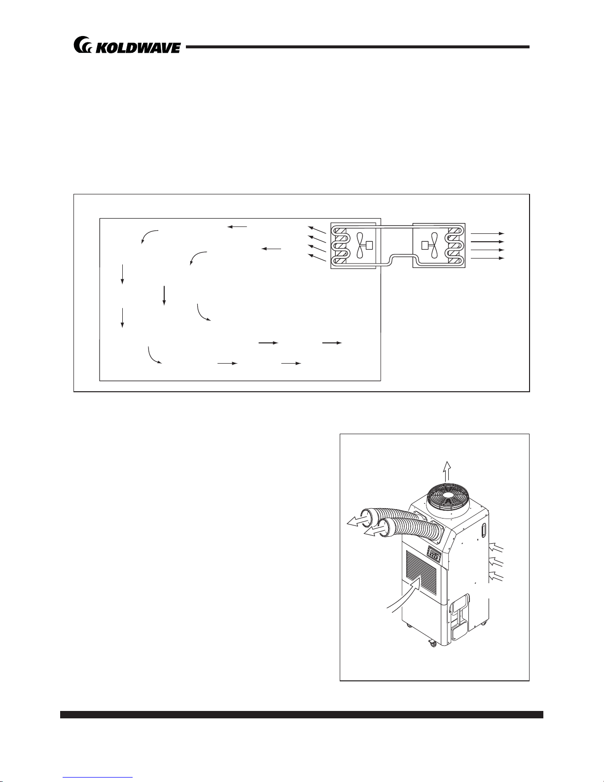
Portable air condi oning system
1) The 5KK14BEA2AA00/5KK21BGA2AA00/5KK
30BGA2AA00 is a spot cooler which directs
cool air to par cular areas or objects.
2) The 5KK14BEA2AA00/5KK21BGA2AA00/5KK
30BGA2AA00 has the following features.
3) The innova ve design of the KK14BEA2AA
00/5KK21BGA2AA00/5KK30BGA2AA00 has
resulted in one compact unit, replacing the
need for two separate units.
4) With the whole cooling system built into one
compact unit, the 5KK14BEA2AA00/5KK21BG
A2AA00/5KK30BGA2AA00 requires no piping
and can be easily transported and installed.
5) The 5KK14BEA2AA00/5KK21BGA2AA00/5KK
30BGA2AA00 is economical because it cools
only the area or objects which need to be
cooled.
Condenser
Outdoor Unit
Evaporator
Indoor Unit
Intake air
(to Evaporator)
Intake air
(to Condenser)
Filter
Filter
Exhaust Hot Air
Cooling Air

page 5
Service Manual
5KK14BEA2AA00 / 5KK21BGA2AA00 / 5KK30BGA2AA00
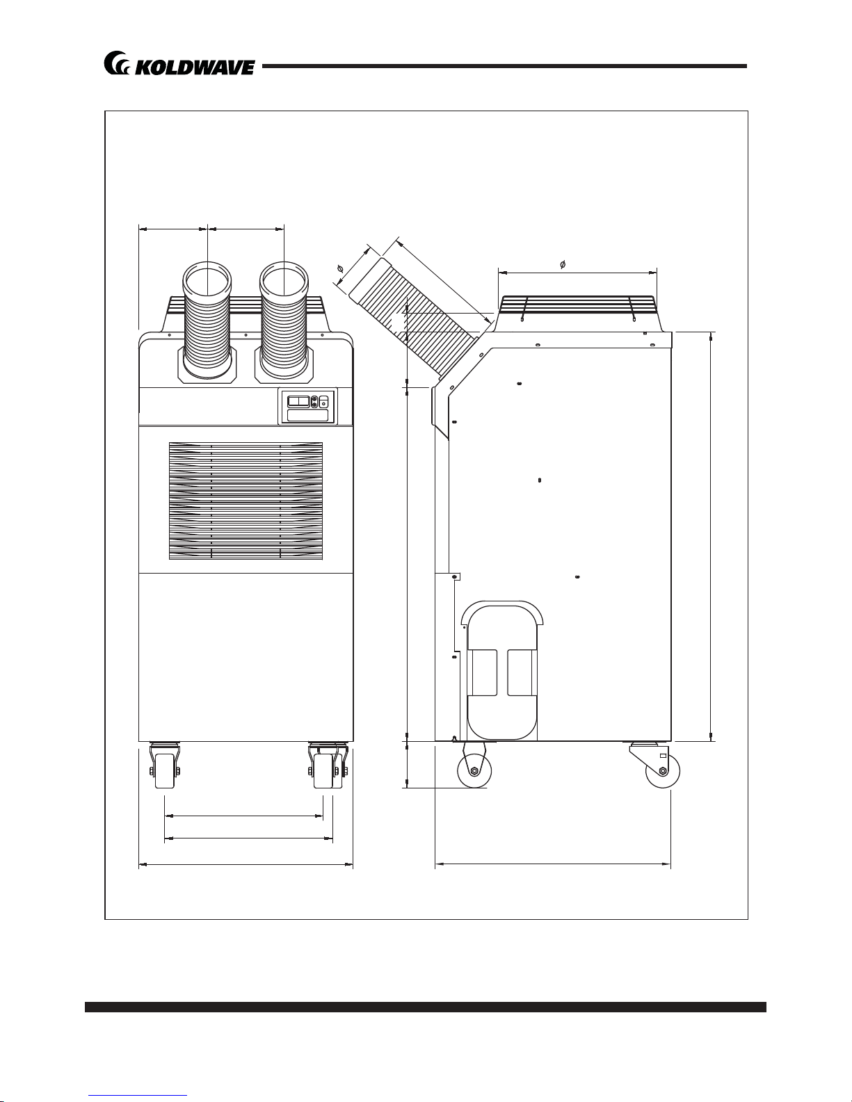
SPECIFICATIONS
Exterior Dimension Diagram
<5KK14BEA2AA00>
4
36.2 2.9
12.5
5.9
36.2
17.5 19.8
13.1
12
5.6
20
6 page
Service Manual
5KK14BEA2AA00 / 5KK21BGA2AA00 / 5KK30BGA2AA00
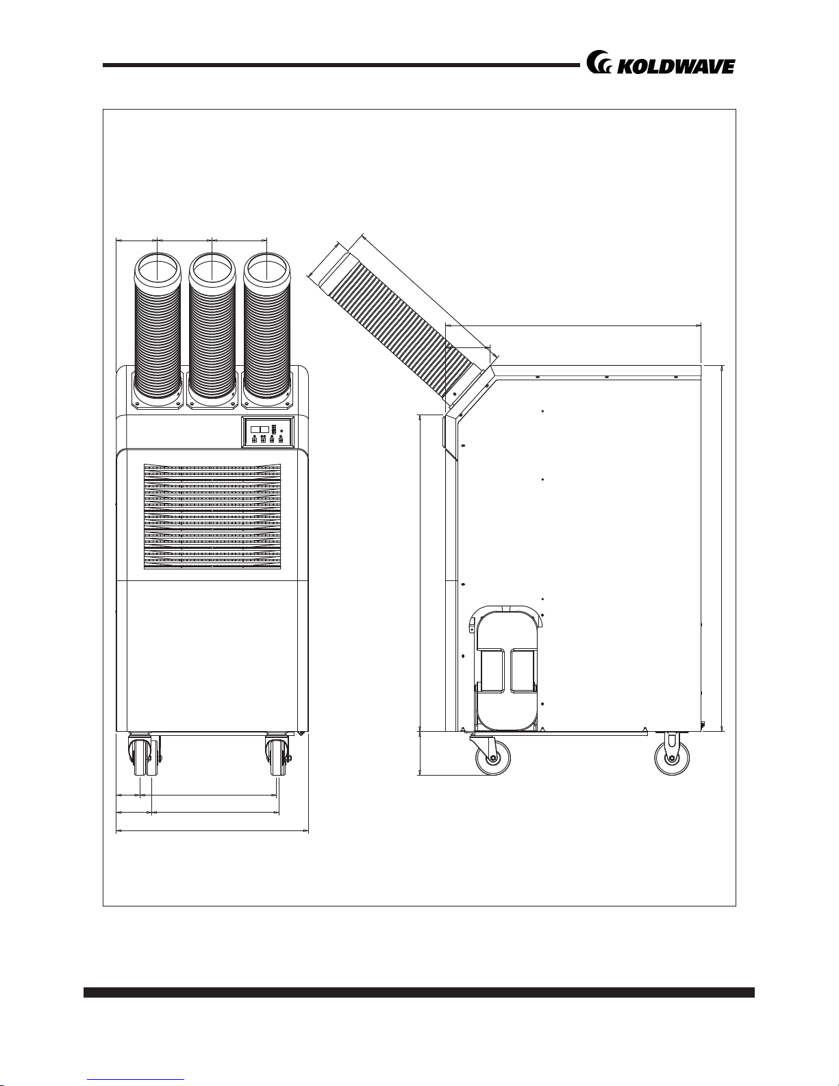
<5KK21BGA2AA00>
22.1
17.3
16.3
7.87.1
4.8 36.4 5.6 1.9
16.3
5.9
42.1
20
24.4
page 7
Service Manual
5KK14BEA2AA00 / 5KK21BGA2AA00 / 5KK30BGA2AA00
<5KK30BGA2AA00>
4.7 6.2 6.2
2.6 15.7
4.0 15.2
22.1
5 36.4
21
OD. Ø5.2
29.4
5.1
42.2

8 page
Service Manual
5KK14BEA2AA00 / 5KK21BGA2AA00 / 5KK30BGA2AA00
Specifi ca ons Unit 5KK14BEA2AA00 5KK21BGA2AA00 5KK30BGA2AA00
Cooling Capacity Btu/h 13,200 19,500 / 21,000 28,000 / 29,000
Power Supply
Phase Single Single Single
Volts 115 208 / 230 208 / 230
Hertz 60 60 60
Power Consump on Wa s 1,300 2,300 3,300
Rated Current Amps
To s h i b a
11.5
LG
10.9
11.0 / 10.0 15.1 / 14.8
EER Btu/Wh 8.6 8.9 9.3
Circuit Breaker Size Amps 15 15 20
Nema Plug Type 5-15P 6-15P 6-20P
Power Cord Gauge Awg 14 14 12
Power Cord Length 10 6 10
Dimensions (W x H x D) In .( mm )
17.5 x 19.9 x 43.3
(445 x 508 x 1092)
22.0 x 24.4x 50.4
(558 x 620 x 1280)
22.1 x 29.4x 47.3
(561 x 746 x 1200)
We ight (Net / Gross) Lbs(kg) 132 / 145.5 (60 / 66) 198 / 216 (90 / 98) 216 / 234 (98 / 106)
Condensate tank Gallons(Liters) 3.17 (12) 3.17 (12) 3.17 (12)
No. of Cool Air Outlets Pcs 1 2 3
Ambient temperature
range
˚F(˚C) 64~113 (18~45) 64~113 (18~45) 64~113 (18~45)
Se ng temperature
(Room cool mode)
˚F(˚C) 64~86 (18~30) 64~86 (18~30) 64~86 (18~30)
Se ng temperature
(Spot cool mode)
˚F(˚C) 32~86 (0~30) 32~86 (0~30) 32~86 (0~30)
Applica on Area (Room
cool mode)
²(m²) 377 (35) 527 (50) 743 (70)
Refrigerant
Type R-410A R-410A R-410A
oz(g)
To s h i b a
15.9 (451)LG15.5 (440)
42.3 (1200) 44.4(1250)
Design Pressure - Hi/Low Psig
To s h i b a
450 / 250LG450 / 270
450 / 250 450 / 280
Indoor Air Flow (High/
Low)
CFM(CMH)
283 / 247
(480 / 420)
512 / 477
(870 / 810)
741 / 635
(1560/ 1447)
Wheels
pcs 4 4 4
diameter 76mm 102mm 102mm
Hot Air Duct Diameter In.(mm) 12 (300) 16 (400) 16 (400)
Maximum Duct Length (m) 16 (5) 30 (9) 60 (18)
Safety Devices
Compressor overload protector, An -freezing thermister, Full drain tank switch,
Autome c restart (Power interrup on), Compressor me delay program, High
pressure switch
Features
Temperature control, Self-diagnos c func on, Two sppeds fan, Op onal drain
pump kit, Washable fi lters, ˚F(˚C) display
Technical Specifi ca ons

page 9
Service Manual
5KK14BEA2AA00 / 5KK21BGA2AA00 / 5KK30BGA2AA00
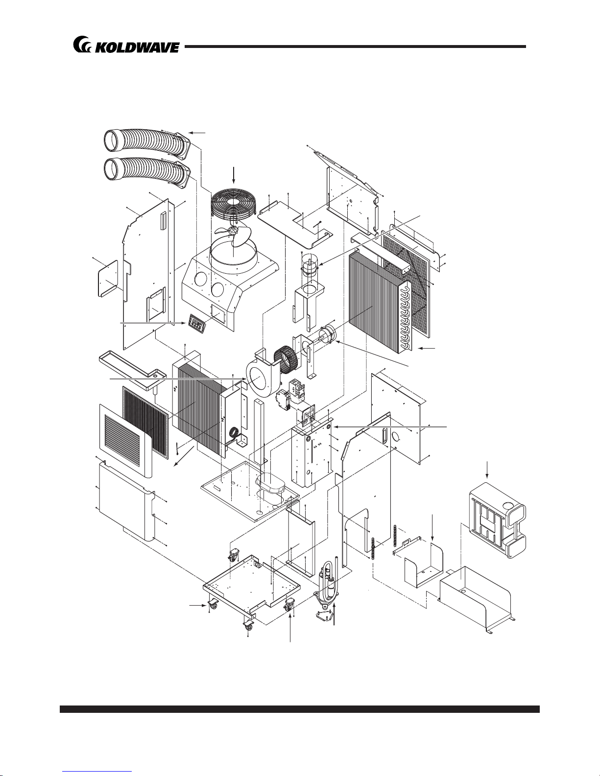
Condenser
Condenser Motor
Evaporator
Cooling Air Duct
Condenser Air Outlet
Control Box
• Relay Board
• Capacitor
Drain Tank
Drain Tank Switch
Compressor
Locking Swivel Caster
Caster (Rear)
Eva Scroll
Control Panel
Evaporator Motor
CONSTRUCTION
Internal Structure
<5KK14BEA2AA00>
10 page
Service Manual
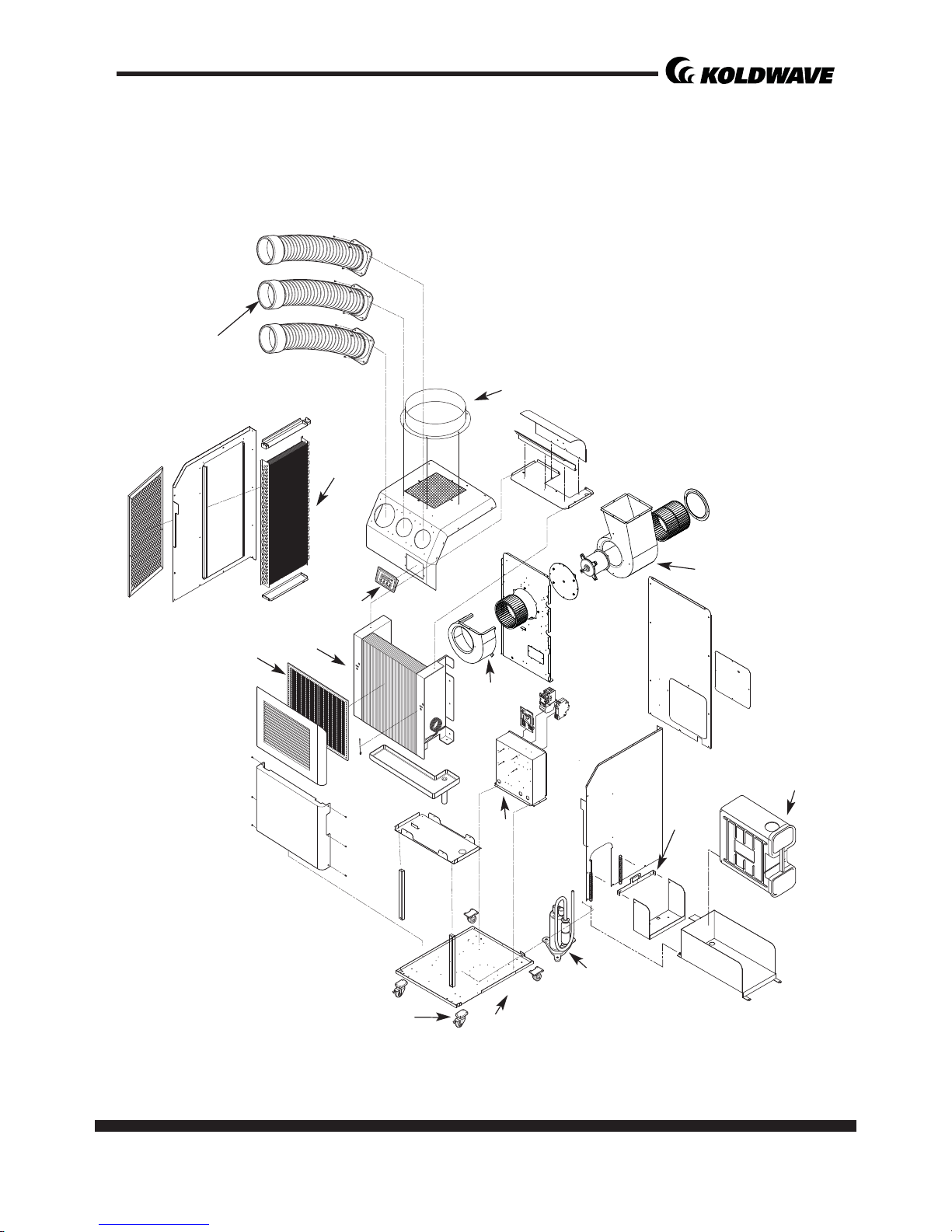
5KK14BEA2AA00 / 5KK21BGA2AA00 / 5KK30BGA2AA00
Control Panel
Eva Scroll
Drain Tank
Drain Tank Switch
Condenser
Condenser Motor
Control Box
• Relay Board
• Capacitor
Caster (Rear)
Locking Swivel Caster
Compressor
Evaporator
Evaporator Motor
Cooling Air Duct
Condenser Air Outlet
<5KK21BGA2AA00>
page 11
Service Manual
5KK14BEA2AA00 / 5KK21BGA2AA00 / 5KK30BGA2AA00
Control Panel
Eva Scroll
Condenser
Control Box
• Relay Board
• Capacitor
Caster (Rear)
Locking Swivel Caster
Compressor
Drain Tank Switch
Drain Tank
Evaporator
Eva Filter
Evaporator Motor
Cooling Air Duct
Cowl
<5KK30BGA2AA00>

12 page
Service Manual
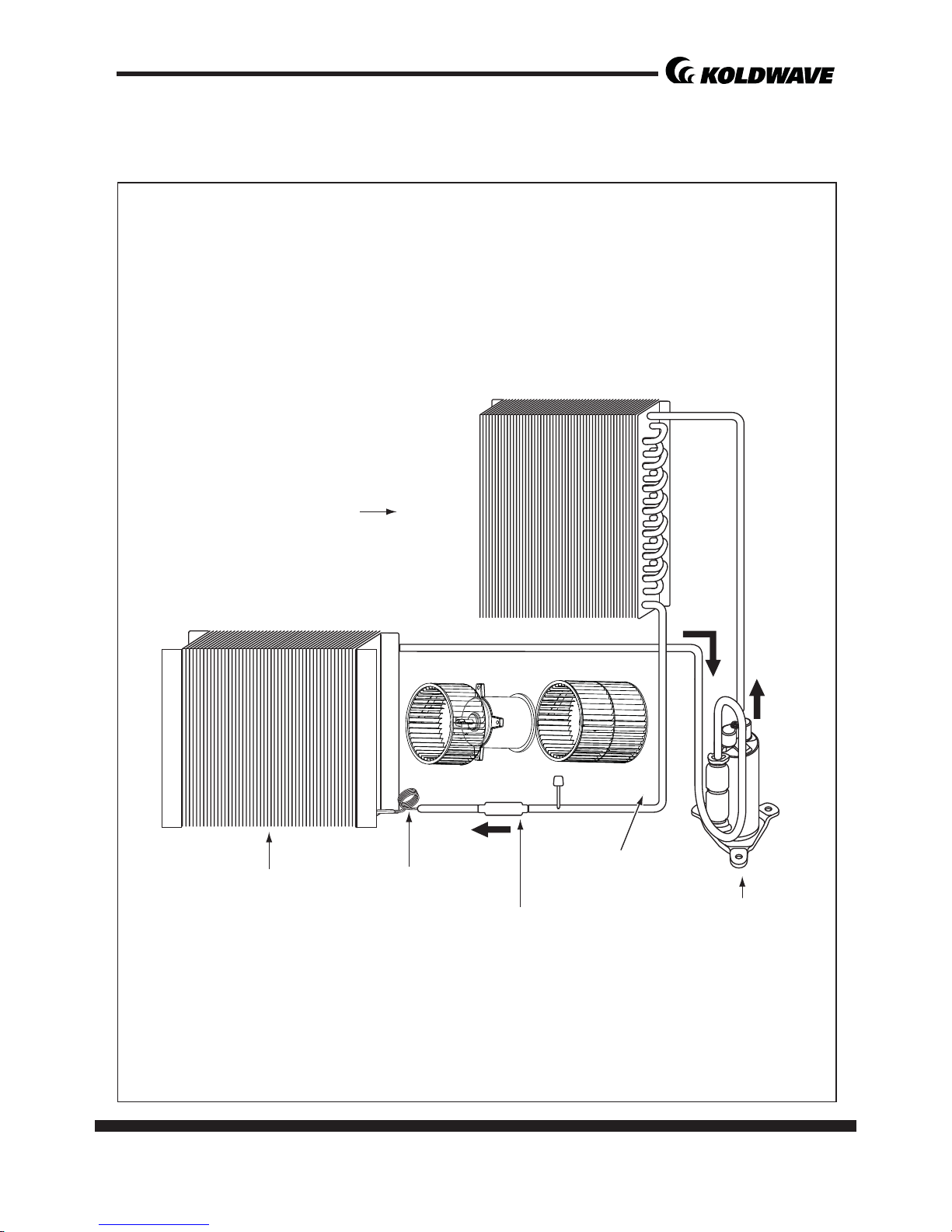
5KK14BEA2AA00 / 5KK21BGA2AA00 / 5KK30BGA2AA00
Flow of
Refrigerant
Condenser Air Outlet
Condenser Motor
Compressor
Accumulator
Evaporator Capillary tube
Drier
Condenser
REFRIGERANT SYSTEM CONSTRUCTION
<5KK14BEA2AA00,5KK21BGA2AA00>
page 13
Service Manual
5KK14BEA2AA00 / 5KK21BGA2AA00 / 5KK30BGA2AA00
Compressor
Accumulator
Evaporator Capillary tube
Drier
Condenser
<5KK30BGA2AA00>
14 page
Service Manual
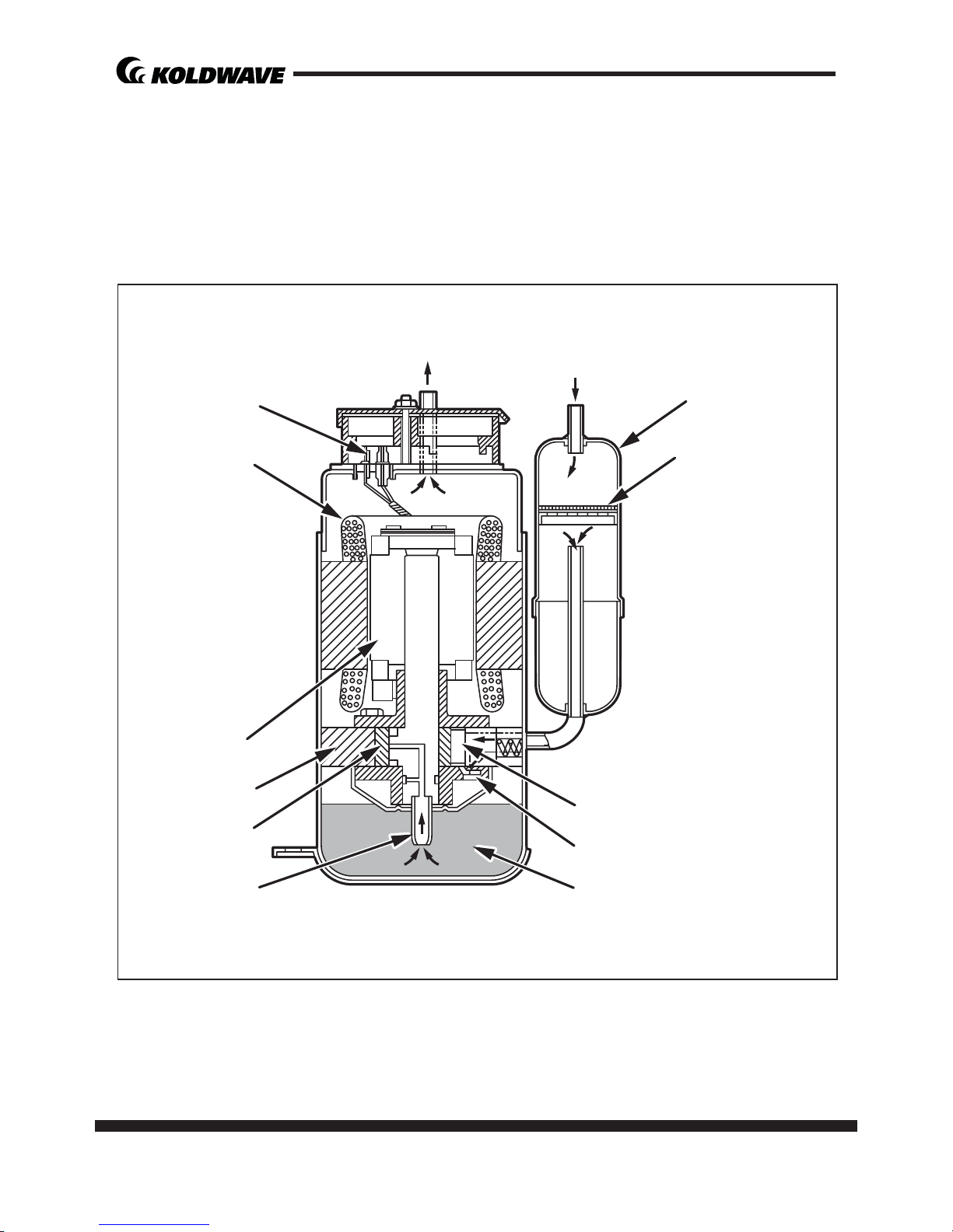
5KK14BEA2AA00 / 5KK21BGA2AA00 / 5KK30BGA2AA00
Compressor
The construc on of a rotary type compressor is divided into two mechanisms; the
drive mechanism (compressor motor), and the compression mechanism (compressor). When the rotor sha of the motor (drive mechanism) turns, the roller (compression mechanism) rotates to compress the refrigerant.
To Condenser
Accumulator
Strainer
From Evaporator
Blade
Discharge Valve
Oil
Lubricator
Roller
Cylinder
Rotor
Stator
Terminal

page 15
Service Manual
5KK14BEA2AA00 / 5KK21BGA2AA00 / 5KK30BGA2AA00
Compressor opera on
1) Start of compression
1) The cylinder is fi lled with low pressure gas.
2) Since pressure in the discharge chamber
is higher than in the cylinder, the discharge valve is kept closed.
2) Suc on and compression
1) The pressure in the cylinder increases
gradually.
2) Refrigerant suc on begins on the suc on side of the cylinder.
3) The discharge valve remains closed.
3) Discharge
1) The pressure in the cylinder exceeds that
in the discharge chamber, and the discharge valve opens.
2) On the suc on side, refrigerant suc on
con nues.
4) Comple on of compression
1) When compression is completed, all of
the refrigerant has been drawn from the
suc on chamber.
2) Opera on then returns to step 1)(Start
of compression) and the above process
of suc on and compression con nues
repeatedly in succession.
Blade
Discharge
Valve
Roller
Blade
Discharge
Valve
Roller
Blade
Discharge
Valve
Roller
Blade
Discharge
Valve
Roller
16 page
Service Manual
5KK14BEA2AA00 / 5KK21BGA2AA00 / 5KK30BGA2AA00
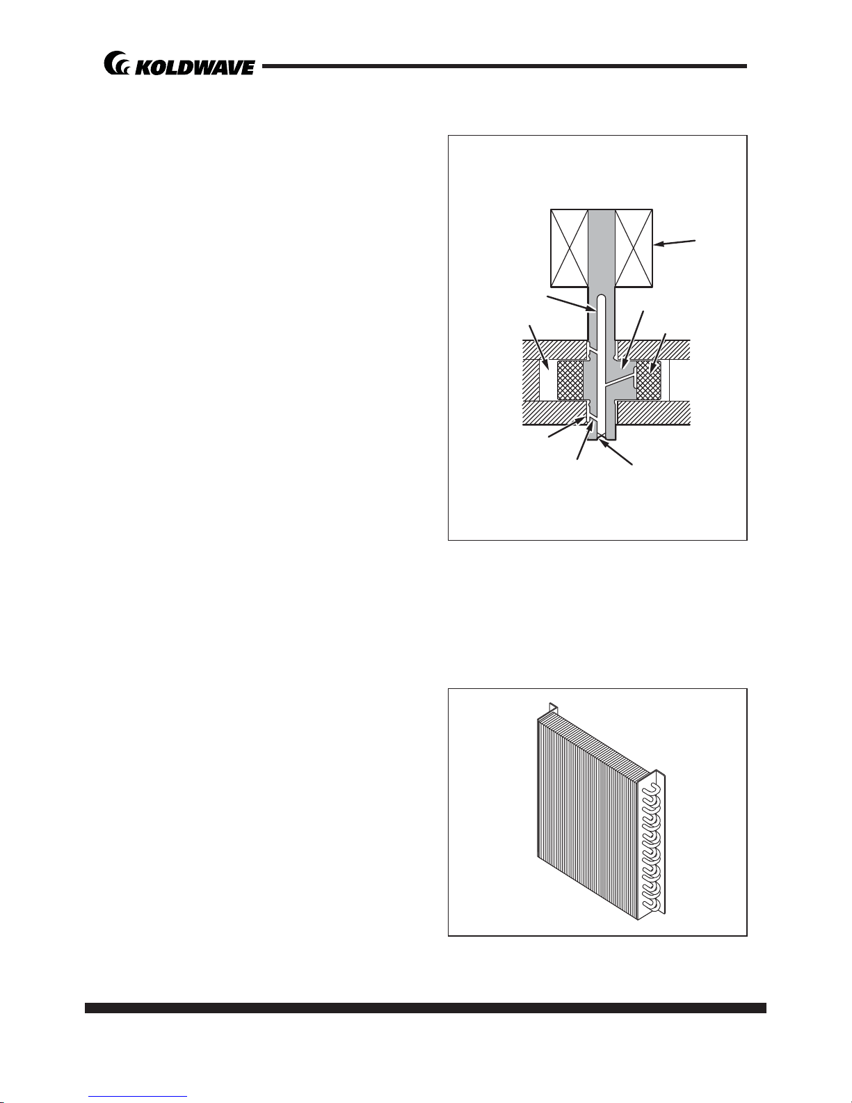
Compressor lubrica on
The lubrica on system is comprised of a
hollow sha , an oil scraper mounted at the
end face, hollow sha , a sha journal (sha
bearing), and the lubrica on groove for the
sha journal.
The lubrica on groove is wider than the oil
hole. When the sha turns, oil is scraped
upward by the oil scraper along the inside
diameter of the hollow sha . The oil is fed
through the oil hole by centrifugal force,
then supplied to the lubrica on groove for
each sha journal, lubrica ng the bearing.
In this lubrica on system, oil enters into
each bearing separately and returns to the
oil reservoir. This system eff ec vely prevents bearing temperature increases, and
off ers high reliability.
In addi on, the specially treated sha journal keeps the bearing from being
damaged during high temperature opera on.
Condenser
1) The condenser is a heat exchanger with
Louver fi ns.
2) Heat is given off and absorbed by air be-
ing pulled across the condenser fi ns by
the axial fan. The air is then expelled
through the condenser air outlet.
Oil Feed Groove
Oil Hole
Oil Scrapper
Roller
Rotor
Cylinder
Hollow Sha
Eccentric Sha
page 17
Service Manual
5KK14BEA2AA00 / 5KK21BGA2AA00 / 5KK30BGA2AA00
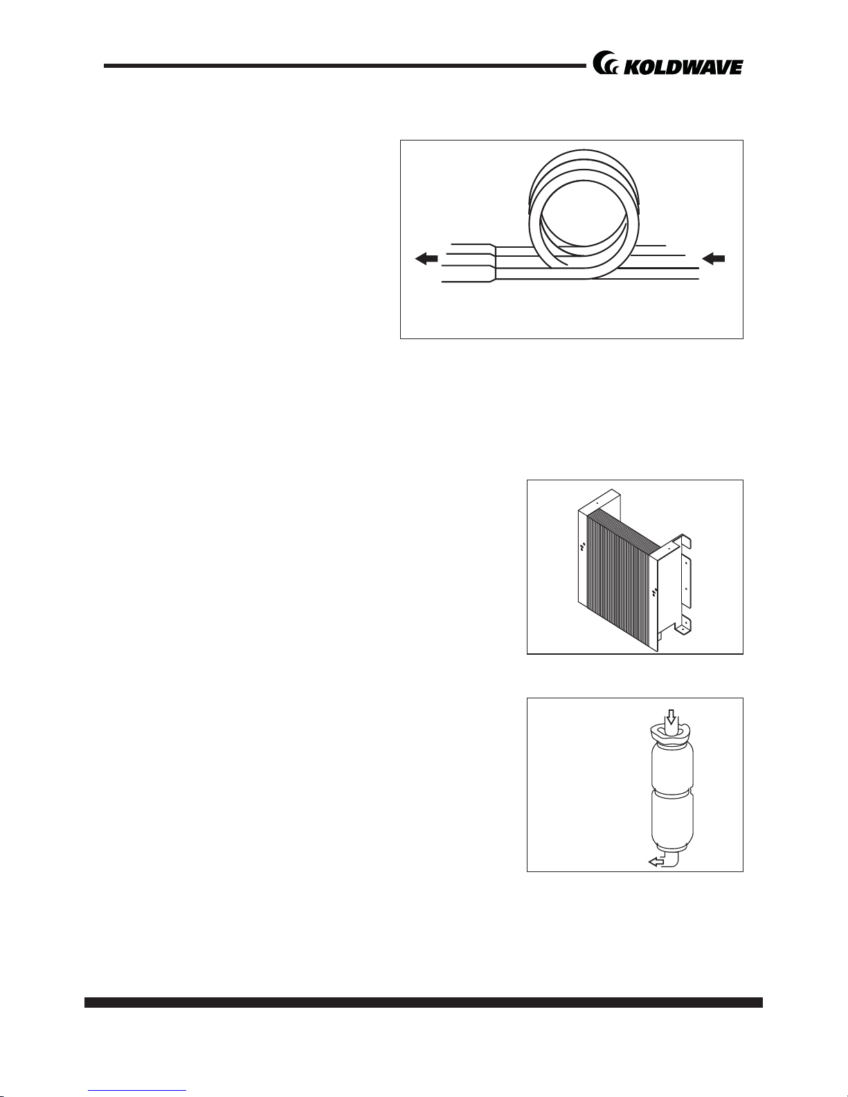
Capillary Tube
The capillary tube is a long thin tube
that u lizes line fl ow resistance as an
expansion valve. The length and the
inner diameter of the capillary tube
are determined according to the capacity of the refrigera on system,
opera ng condi ons, and the amount
of refrigerant. The high pressure, high
temperature liquid refrigerant sent
from the condenser expands rapidly as
the refrigerant is sprayed out through the fi xed orifi ce in the capillary tube. As a
result, the temperature and state of the refrigerant becomes low and mist-like, and
therefore evaporates easily.
Evaporator
The evaporator is a heat exchanger covered with slit
fi ns. Heat is removed from the air being pulled across
the evaporator by the centrifugal fan.
The resul ng cool air is expelled through the cooling air
ducts.
Accumulator
The accumulator is mounted on the suc on gas piping between the evaporator and the compressor.
The accumulator separates the liquid refrigerant from
the gas refrigerant, allowing only the gas refrigerant to
enter the compressor. In the accumulator, suc on gas
isled into a cylindrical vessel where the speed of the
gas is decreased.
This process separates the refrigerant contained in
the gas by the force of gravity, causing the refrigerant to accumulate at the bo om
of the vessel. As a result, the compressor is protected from possible damage caused
by liquid refrigerant intake.
High Temp./High Pressure
Liquid Refrigerant
Low Temp./Low Pressure
Gas and Liquid Mixture
From Evaporator
To Compressor
18 page
Service Manual
5KK14BEA2AA00 / 5KK21BGA2AA00 / 5KK30BGA2AA00
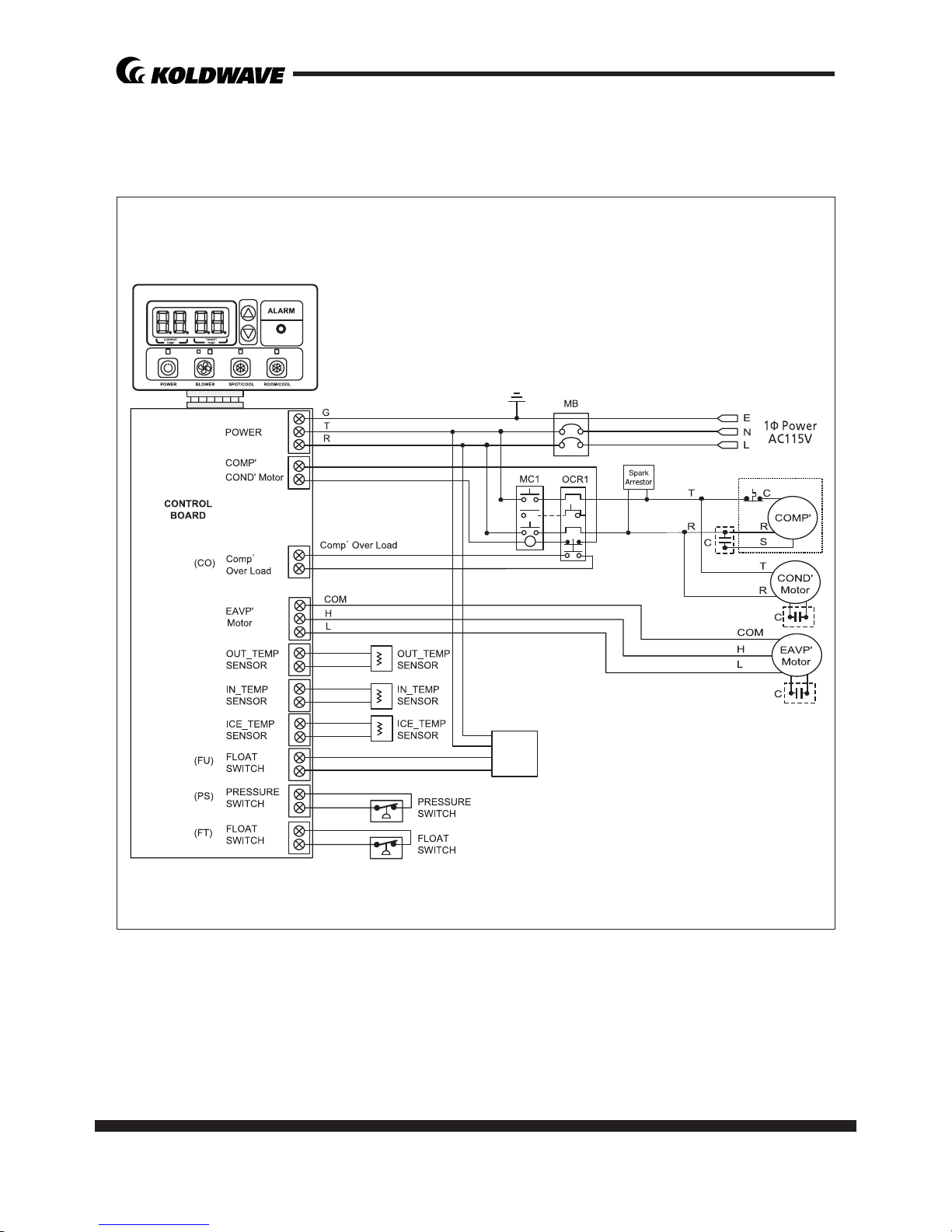
ELECTRICAL SYSTEM
Circuit Diagram
<5KK14BEA2AA00, 5KK21BGA2AA00>
(TH1)
(TH2)
(TH3)
DRAIN
PUMP
page 19
Service Manual
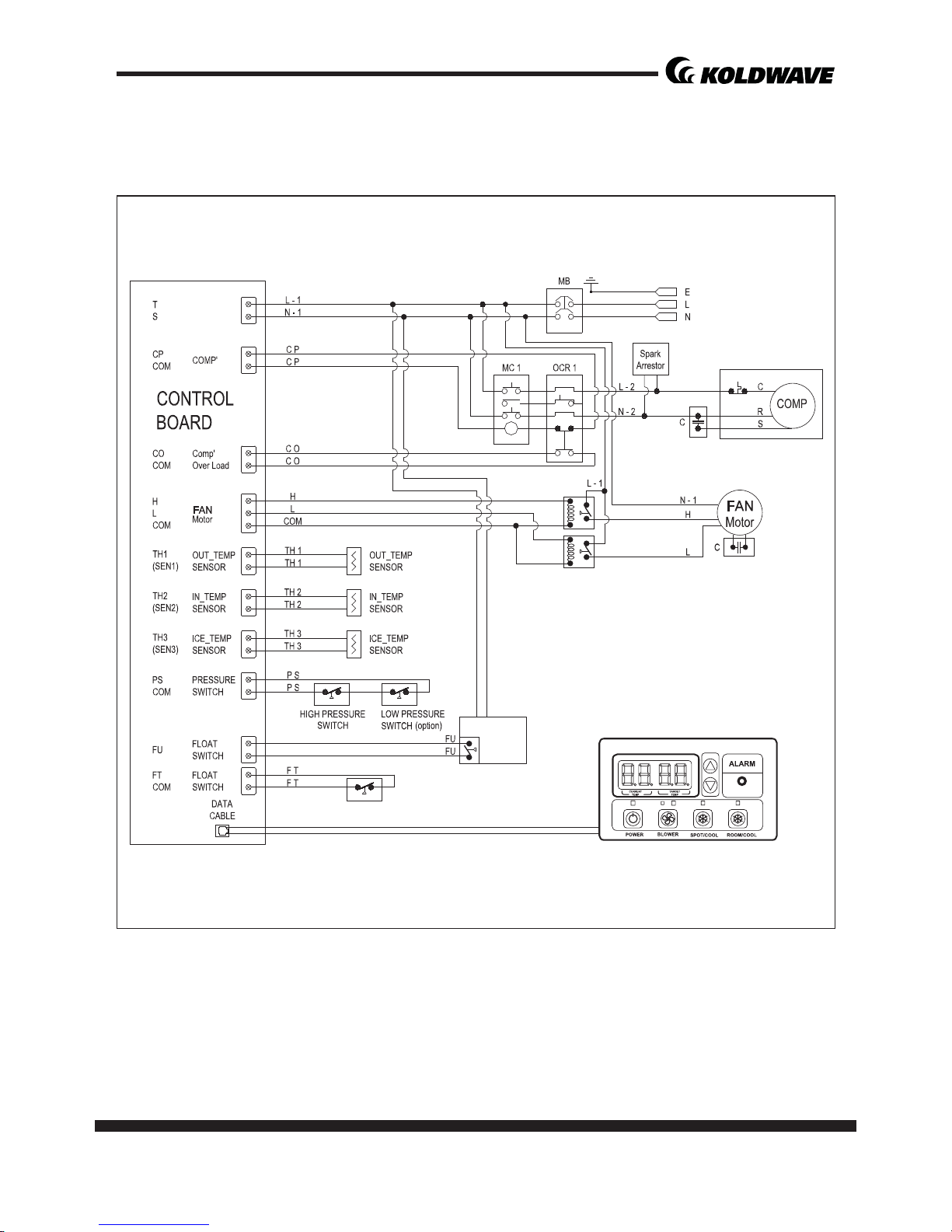
5KK14BEA2AA00 / 5KK21BGA2AA00 / 5KK30BGA2AA00
<5KK30BGA2AA00>
DRAIN
PUMP
(option)
RELAY
RELAY
POWER
1P AC 208/230V
(AC115)
POWER
1P AC 208/230V
(AC115)
20 page
Service Manual
5KK14BEA2AA00 / 5KK21BGA2AA00 / 5KK30BGA2AA00
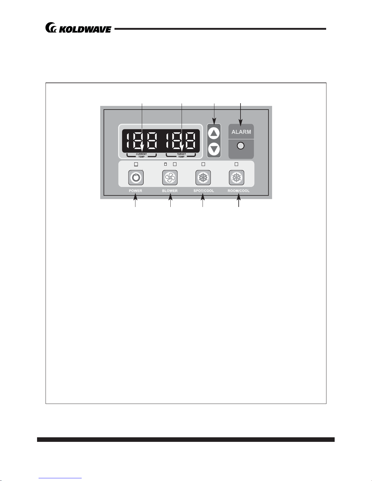
Control panel
Before opera ng the unit, it is important to be familiar with the basic opera on of
the control panel.
1. POWER BUTTON
• Ac vates unit when POWER BUTTON is pressed.
• Fan starts on low speed.
• If POWER BUTTON is pressed during opera on, unit stops.
2. BLOWER BUTTON
• Changes fan speed from LOW to HIGH when pressed.
3. SPOT / COOL BUTTON
• Ac vates compressor and begins producing cool air 5 seconds a er
bu on is pressed.
• Regulates temperature based on outlet cool air temperature.
4. ROOM / COOL BUTTON
• Ac vates compressor and produces cool air 5 seconds a er bu o n
is pressed.
• Regulates temperature based on inlet ambient air temperature.
1 2
5
3 4
6
87
 Loading...