

Koldwave 5AK39BFA, 5AK65BFA, 5AK39BGA, 5AK65BGA, 5AK65BAA Maintenance Manual
...
IOM5AKEN-2
Koldwave 5AK39 and 5AK65 Series Installation,
Operation & Maintenance Manual
ATTENTION: READ THIS MANUAL, FACTORY INSTALLED OPTIONS MANUAL,
UNIT SUBMITTAL DATA SHEETS AND ALL LABELS ATTACHED TO THE UNIT
CAREFULY BEFORE ATTEMPTING TO INSTALL, OPERATE OR SERVICE
THESE UNITS. CHECK DATA PLATES FOR ELECTRICAL SPECIFICATIONS
AND MAKE CERTAIN THAT THESE AGREE WITH THOSE AT THE POINT OF
INSTALLATION. RECORD THE UNIT MODEL AND SERIAL NUMBER IN THE
SPACE PROVIDED. RETAIN THIS DOCUMENT FOR FUTURE REFERENCE.
Model No._______________________ Serial No._______________________________
IMPROPER INSTALLATION, ADJUSTMENT, ALTERATION, SERVICE OR
MAINTENANCE CAN CAUSE PROPERTY DAMAGE, INJURY OR DEATH. THIS
APPLIANCE MUST BE INSTALLED BY A LICENSED CONTRACTOR OR
QUALIFIED SERVICE PERSONNEL. READ THESE INSTALLATION, OPERATING
AND MAINTENANCE INSTRUCTIONS THOROUGHLY BEFORE INSTALLING OR
SERVICING THE UNIT.
WARNING: INSTALL, OPERATE AND MAINTAIN UNIT IN ACCORDANCE WITH
MANUFACTURER’S INSTRUCTIONS TO AVOID ANY DETURING FACTORS
THAT MAY CAUSE PERSONAL INJURY OR PROPERTY DAMAGE.
INSTALLER’S RESPONSIBILITY: THIS EQUIPMENT HAS BEEN RUN TESTED
AND INSPECTED THOROUGHLY. IT HAS BEEN SHIPPED FREE FROM
DEFECTS FROM OUR FACTORY. HOWEVER, DURING SHIPMENT AND
INSTALLATION, PROBLEMS SUCH AS LOOSE WIRES, LEAKS, OR LOOSE
FASTENERS MAY OCCUR. IT IS THE INSTALLER’S RESPONSIBILITY TO
INSPECT AND NOTIFY FACORY OF ANY PROBLEMS THAT MAY BE FOUND.
Koldwave 4830 Transport Drive Dallas, TX 75247 Ph: 214-638-6010
www.koldwave.com
1

IOM5AKEN-2
Table of Contents:
GENERAL INFORMATION ...................................................................................................... 4
INSTALLATION INSTRUCTIONS .......................................................................................... 5
ELECTRICAL REQUIREMENTS ....................................................................................................... 5
SERVICE CORD ............................................................................................................................. 5
SPECIFICATION AND ELECTRIC DATA ............................................................................. 6
SERVICEABILITY ...................................................................................................................... 7
5AK39
5AK39
UPPER LEFT SIDE VIEW ................................................................................................... 7
UPPER RIGHT SIDE VIEW................................................................................................. 8
5AK39 UPPER LEFT SIDE VIEW ................................................................................................... 9
5AK39 UPPER RIGHT SIDE VIEW............................................................................................... 10
5AK65 LOWER LEFT SIDE VIEW ............................................................................................... 11
5AK65 UPPER LEFT SIDE VIEW ................................................................................................. 12
5AK65 FRONT VIEW ................................................................................................................. 12
AIR FILTER ............................................................................................................................... 13
CONDENSATE REMOVAL ..................................................................................................... 13
GENERAL FLOW PATTERN ................................................................................................. 14
SAFETY CONTROLS ............................................................................................................... 14
UNIT OPERATION ................................................................................................................... 15
UNIT POWER ON: ....................................................................................................................... 15
FAN HI: ...................................................................................................................................... 15
FAN LO: ..................................................................................................................................... 15
COOLING HI: .............................................................................................................................. 15
COOLING LO: ............................................................................................................................. 15
EMPERATURE SETTING: ........................................................................................................... 15
T
UNIT OFF: .................................................................................................................................. 15
O
THER SETTINGS: ...................................................................................................................... 15
OMPRESSOR OFF TIME: ............................................................................................................ 15
C
SELF RECOVERY MODE (*): ....................................................................................................... 15
CHECK ALARMS: ........................................................................................................................ 16
O
PTIONAL REMOTE CONTROL: .................................................................................................. 16
INSPECTION AND REPAIR OF ELECTRICAL SYSTEM ................................................ 17
OMPRESSOR AND FAN MOTOR CAPACITORS ............................................................................ 17
C
INSPECTION AND REPAIR OF REFRIGERANT SYSTEM ............................................. 17
PREVENTATIVE MAINTENANCE ....................................................................................... 17
2

IOM5AKEN-2
ELECTRICAL DIAGRAM ....................................................................................................... 19
5AK39, 5AK65 208V/1PH ....................................................................................................... 19
5AK39,
5AK65
5AK65 230V/1PH ....................................................................................................... 20
208V/3PH WITH 208V/1PH PUMP ................................................................................ 21
5AK65 230V/3PH WITH 230V/1PH PUMP ................................................................................ 22
5AK65 460V/3PH WITH 277V/1PH PUMP ................................................................................ 23
TROUBLE SHOOTING GUIDE .............................................................................................. 24
TROUBLE SHOOTING GUIDE CONTINUED ..................................................................... 25
TROUBLE SHOOTING GUIDE CONTINUED ..................................................................... 26
TROUBLE SHOOTING GUIDE CONTINUED ..................................................................... 27
TROUBLE SHOOTING GUIDE CONTINUED ..................................................................... 28
TROUBLE SHOOTING GUIDE CONTINUED ..................................................................... 29
3
General Information
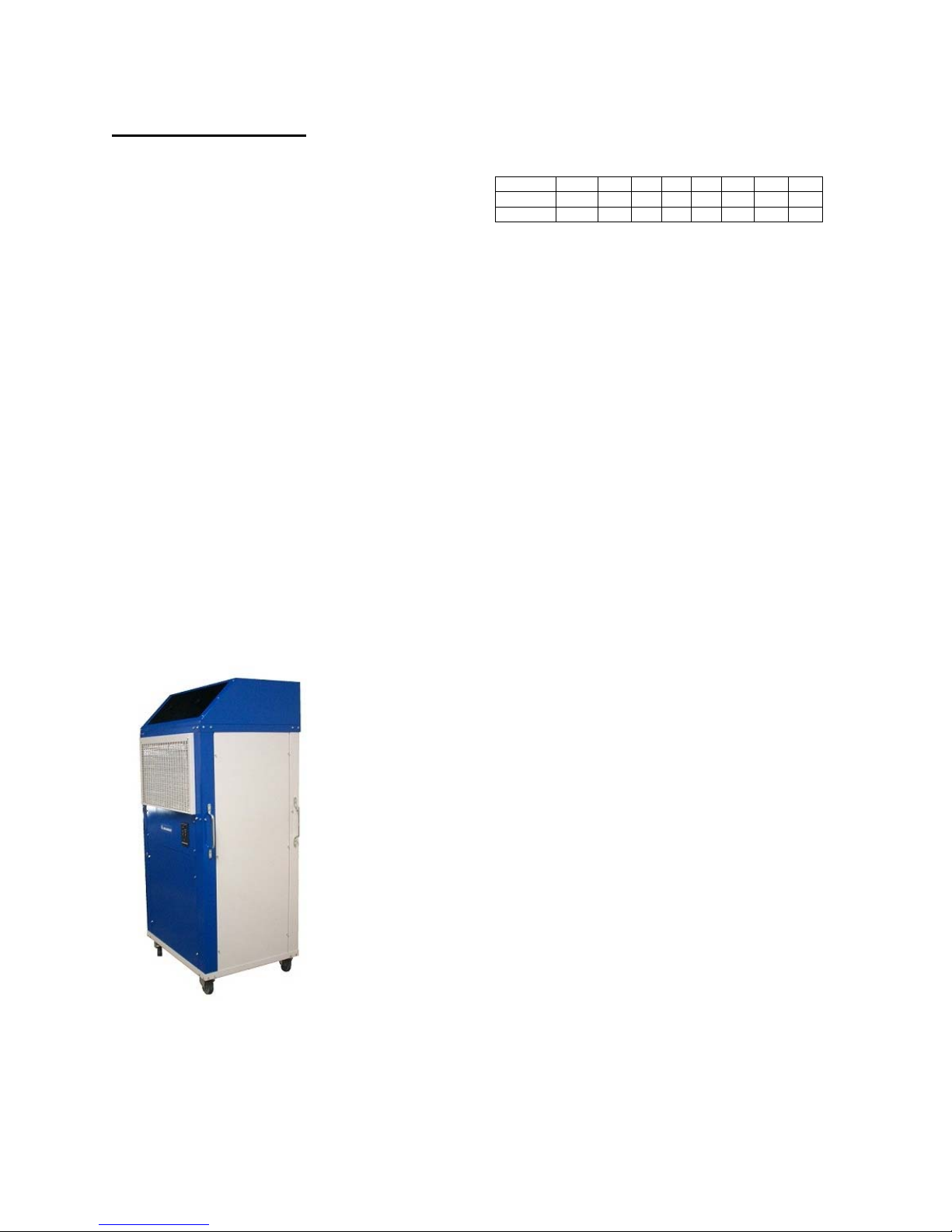
The Koldwave 5AK Series Air Conditioners
are portable, air-cooled air conditioners/zone
coolers suitable for indoor/outdoor use. The
Koldwave air-conditioner cools an entire
area by discharging air through its supply
grille. This self-contained unit is also
designed to direct cool air to specific areas
or objects through (optional) flexible
snozzles®. This provides precision cooling
for heat-sensitive equipment, production
processes and personnel.
Each unit is completely self-contained with
the entire refrigeration system, electrical
components, condenser and evaporator
housed in one cabinet. The Koldwave unit
is provided with heavy-duty casters. Two
swivel-locking casters prevent sliding; two
stationary casters provide handling ease for
relocation.
NOMENCLATURE
Example 5AK 14 B G A 1 A A
Code MD US R V C SS EC CC
Field 1,2,3 4,5 6 7 8 9 10 11
1,2,3 – MODEL (MD)
5AK – Air Cooled Portable
4,5 – UNIT SIZE (US)
AK – Air Cooled Models
39 – 36,800 Btuh
65 – 61,200 Btuh
6 - REFRIGERANT (R)
B – R410A
7 – VOLTAGE (V)
A – 208/3/60 (used only on 5AK65)
B – 230/3/60 (used only on 5AK65)
C – 460/3/60 (used only on 5AK65)
F – 208/1/60
G – 230/1/60
8 – CONFIGURATION (C)
A – Front Discharge with Adjustable Grilles
9 – CONFIGURATION (SS)
1 – Stainless Steel
2 – Painted (5AK65 only)
10 – EVAPORATOR COIL (EC)
A – Standard Copper/Aluminum
11 – CONDENSER COIL (CC)
A – Standard Copper/Aluminum
Model 5AK65
4
Installation Instructions
IMPORTANT: Following the installation
and preventative maintenance instructions
can extend the length of service you
receive from your Koldwave unit.
Electrical Requirements
Check the power supply to make certain it is
within 10% of the voltage listed on the data
plate located on the back of the unit.
Operating the unit on improper voltage
will void the product warranty.
Refer to the Rating Plate for voltage and
current information.
Each unit should have a dedicated circuit
breaker.
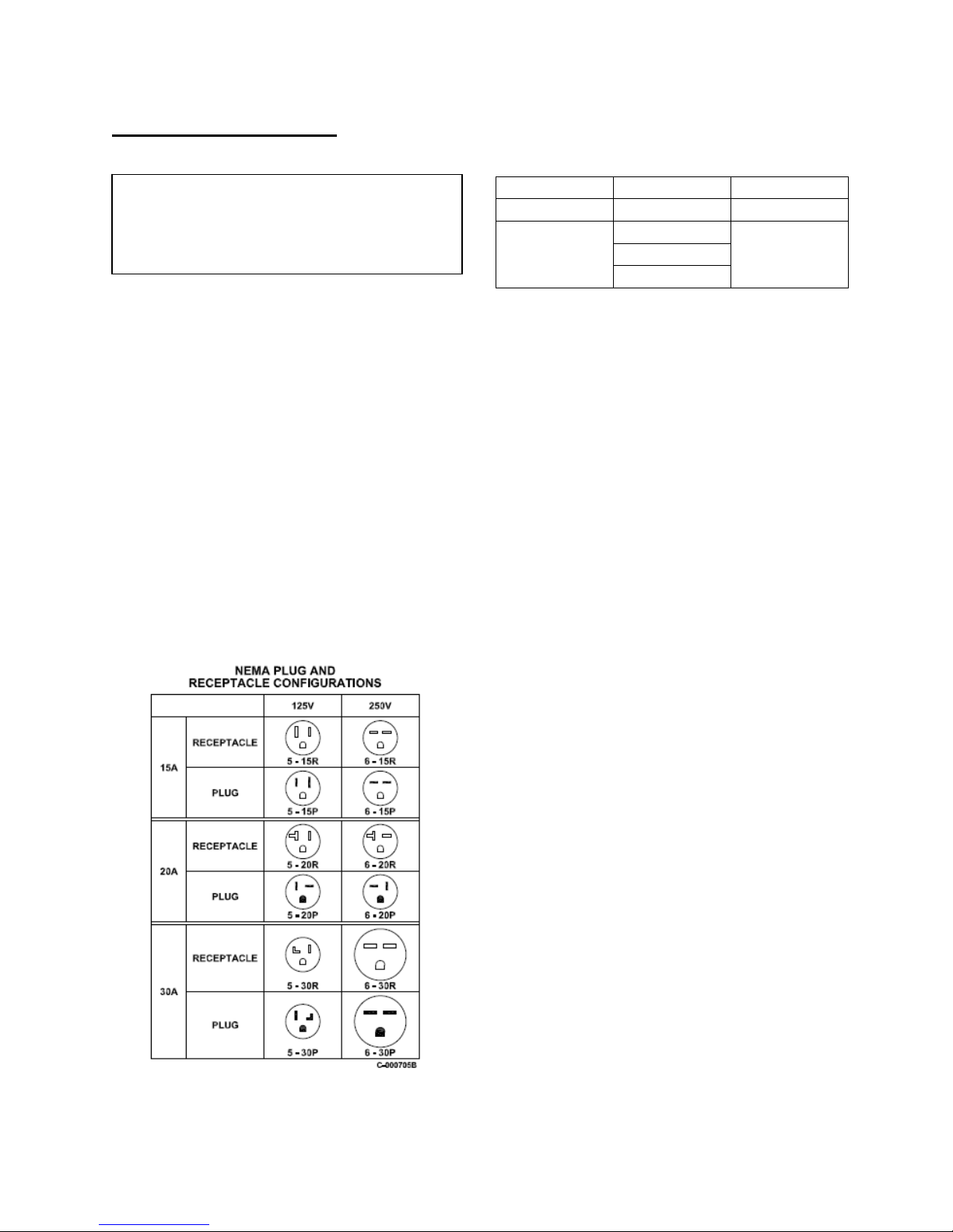
Service Cord
MODEL VOLTAGE PLUG TYPE
5AK39 208-230/1/60 6 – 30P
240/1/60
5AK65
Field wired 240/3/60
460/3/60
Extension cords used with the Koldwave
units should match the plug configuration of
the service cord provided on the unit. The
extension cord must be equipped with an
equipment grounding conductor, a
grounding type attachment plug, and a
grounding type attachment connector. The
cord must also have a rating suitable for the
voltage and ampacity.
The Koldwave 5AK65 is a field wired unit
which requires a field supplied electrical
service disconnect. Check the unit
nameplate for the correct voltage, phase and
maximum fuse size for the electrical service
for the unit. A high voltage terminal block is
provided in the unit’s control box for the
electrical connection. Route the electrical
power leads through the electrical knockouts
provided on either side of the control box.
Install the required electrical service wiring
in accordance with all applicable codes.
5
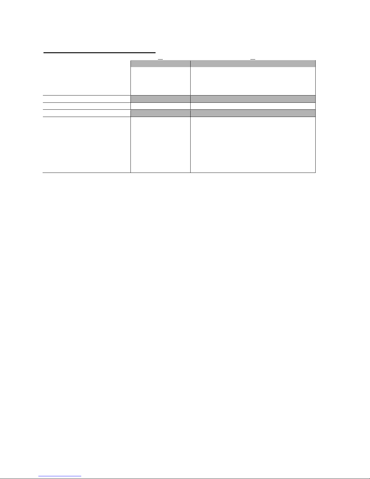
Specification and Electric Data
ELECTRIC DATA
Voltage/Phase/Hertz 230/1/60 230/1/60 230/3/60 460/3/60
Amperage 22.7 49.7 26.1 15.4
Fuse Size (Amps) 30 60 40 30
Watts 4666 8380
REFRIGERANT CHARGE
R410A (Ounces) 116 176
UNIT DIMENSIONS (INCHES)
Height with Casters 69 78
Height without Casters 64 73
Width 40.5 40.25
Depth 31.5 31.5
Evaporator Filter (qty) (1) 13.75 x 29.75 x 0.88 (1) 29.75 x 17.75 x 0.88
Condenser Filter (qty) (1) 23 x 29.5 x 0.88 (1) 29.5 x 29 x 0.88
NET UNIT WEIGHT (LBS.)
SHIPPING WEIGHT (LBS.)
Time delay fuses and circuit breakers are recommended.
*** Electrical ratings per U.L Standard 484 at 95°F DB/75° WB on high speed at 230VAC single phase
except 5AK65 at 230VAC three phase.
### Electrical ratings estimated from component nameplate ratings on high speed.
39
65
*** ### *** ###
590 650
620 700
6
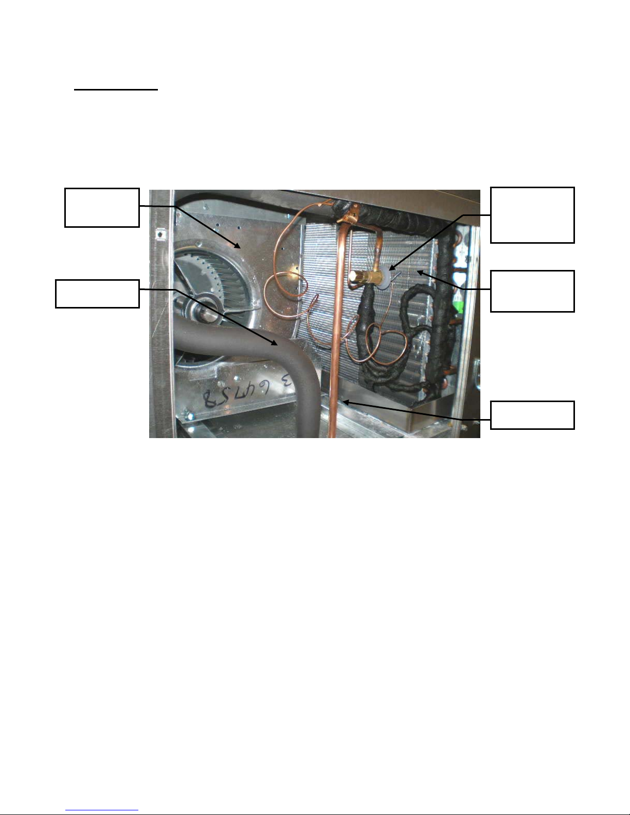
Serviceability
The Koldwave unit has removable panels to provide full service accessibility.
5AK39 Upper Left Side View
Evaporator
Blower
Thermostatic
Expansion
Valve
Suction Line
Evaporator
Coil
Liquid Line
7
r
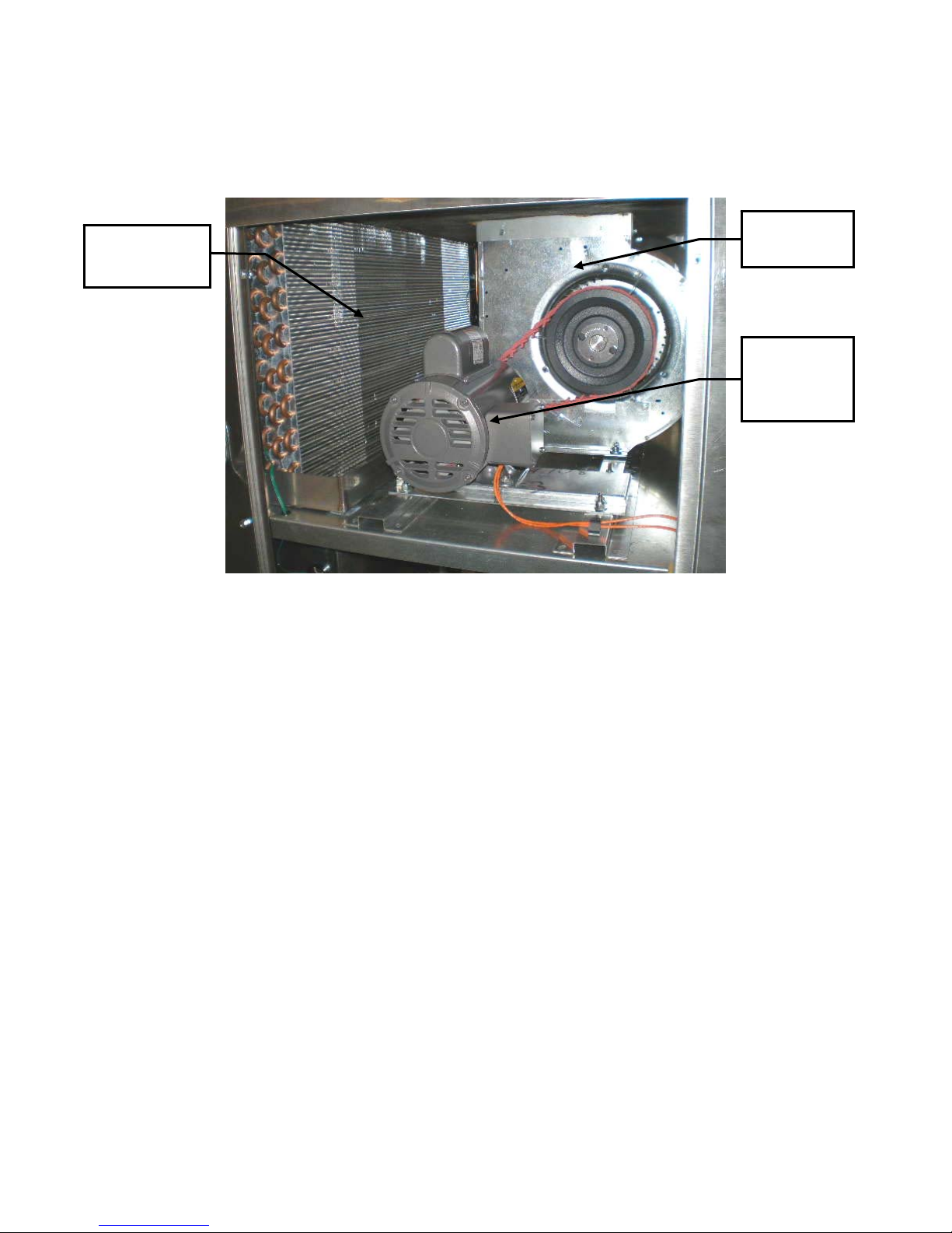
5AK39 Upper Right Side View
Evaporator
Coil
Evaporator
Blowe
Evaporator
Blower
Motor
8
r
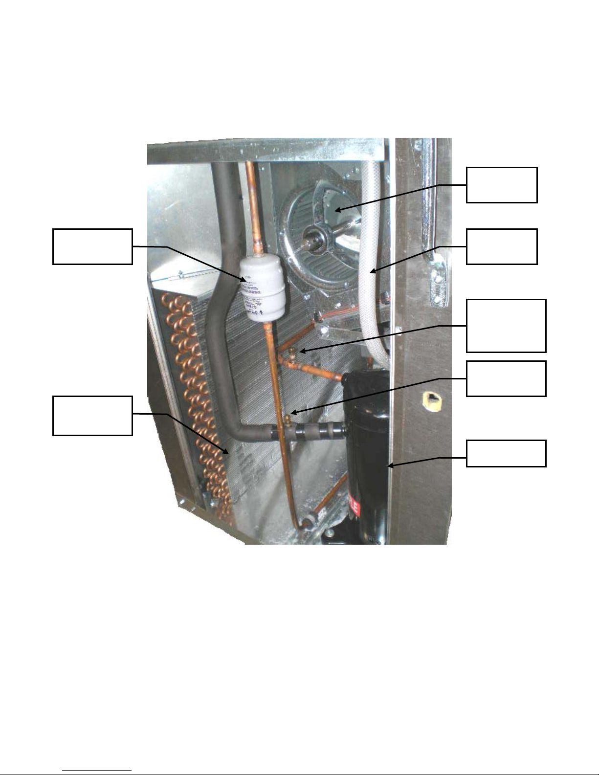
5AK39 Upper Left Side View
Evaporator
Blowe
Liquid Line
Filter/Drier
Condenser
Coil
Drain Pan
Hose
Discharge
Line Service
Port
Suction Line
Service Port
Compressor
9
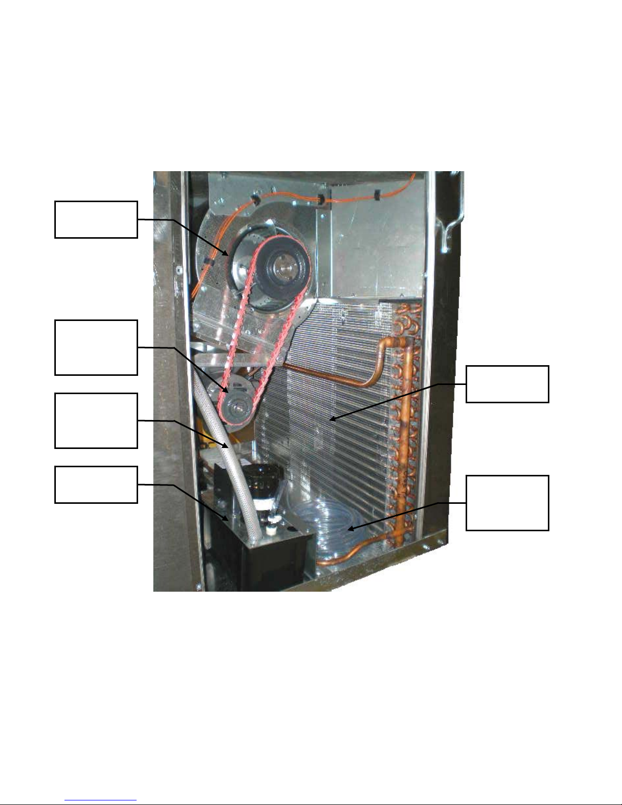
5AK39 Upper Right Side View
Condenser
Blower
Condenser
Blower
Motor
Evaporator
Drain Pan
Hose
Condensate
Pump
Condenser
Coil
Condensate
Pump Drain
Line
10
 Loading...