

Koldware 2K07DBH, 2K14DB, 2K10DB, 2K10DHB, 2K14DHB Installation & Operation Manual
...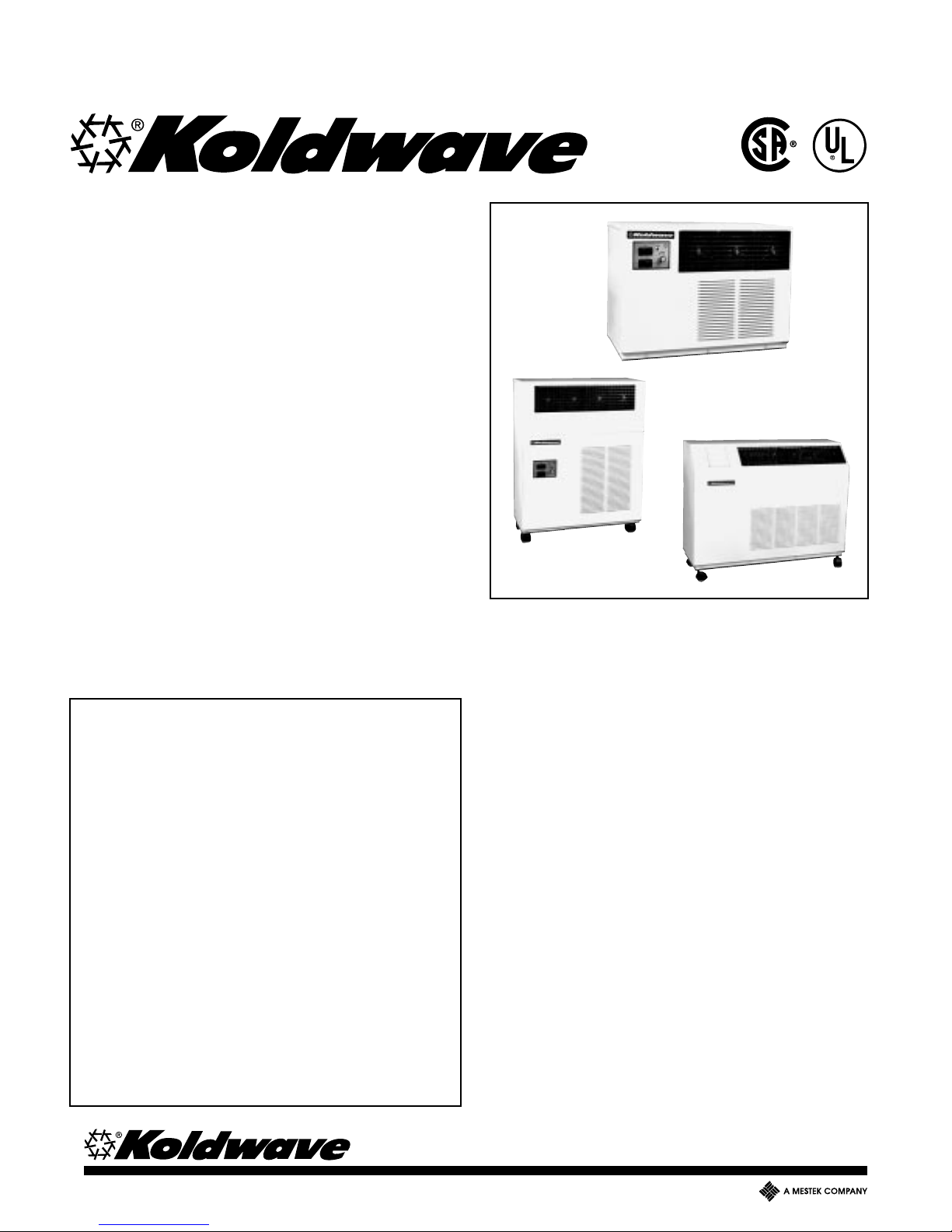
KOMPAC
SERIES
AIR CONDITIONER
KKSM-3
AND HEAT PUMP
INSTALLATION &
OPERATION
MANUAL
Koolette 7,000 Btu/Hr Cooling
Kompac 9,400-16,000 Btu/Hr Cooling
King Kompac 20,500-26,000 Btu/Hr Cooling
GENERAL INFORMATION AND
CAPACITY SELECTION..................................... 1, 2
SPECIFICATIONS .................................................. 3
STANDARD AND OPTIONAL FEATURES ........ 4, 5
INSTALLATION INSTRUCTIONS ...................... 6, 7
CHECKOUT OF UNIT OPERATION ...................... 7
WATER FLOW GRAPH AND
MODES OF OPERATION ................................... 8, 9
UNIT CONSTRUCTION................................... 10-12
PARTS REPLACEMENT PROCEDURE ........ 13, 14
PREVENTIVE MAINTENANCE...................... 14, 15
TROUBLESHOOTING GUIDE ....................... 16, 17
PIPING SCHEMATICS ......................................... 18
WIRING DIAGRAMS ...................................... 19, 20
CERTIFIED DRAWINGS ...................................... 21
LIMITED WARRANTY .......................................... 22
PARTS LIST..................................................... 23,24
7,800 Btu/Hr Heating
10,900-17,900 Btu/Hr Heating
24,000-31,000 Btu/Hr Heating
KOOLETTE
KOMPAC
KING KOMPAC
GENERAL INFORMATION
DESCRIPTION
Kompac Series Air Conditioners and Heat Pumps are
designed for applications where outside air is not
available and spot cooling is required. The cord
connected Kompac Models range from a 7,000 Btu/Hr
countertop to a 26,000 Btu/Hr floor mount configuration
to meet any space requirements. Kompac and King
Kompac models are provided with casters f or portability.
All Models are completely self-contained with the entire
refrigeration system, fan motor , w ater valve, and
electrical components housed in a metal cabinet with a
baked enamel finish. Only power and condenser water
supply, water discharge, and condensate drain piping
are required for installation. With the heat pump option,
automatic changeover from cooling to heating to cooling
provides the desired comfort, depending upon
thermostat command.
The water-cooled condenser requires only that amount
of water needed to achiev e the desired high and lo w
refrigeration system pressures. The condenser water
flow rate for an y entering water temperature can be
obtained using the graph on page 8. Condenser w ater is
regulated by a refrigeration system head pressure
actuated water regulating valve.
260 NORTH ELM STREET • WESTFIELD , MA 01085 • Tel: (413) 564-5520 • F ax: (413) 564-5815

KOLDWAVE KOMPAC SERIES (KOOLETTE, KOMPAC, AND KING KOMPAC)
GENERAL REQUIREMENTS
For proper control of the water flow rate entering the
automatic water valve, the minimum water pressure
required for condenser water supply is 30 PSIG.
The condenser water temperature leaving the unit
should not exceed 110°F. Ignoring this compliance will
void the warranty on the refrigeration system. On heat
pump models, it is not recommended to operate the
unit in the heating cycle when the water inlet
temperature is below 50°F. Doing so could reduce the
specified heating capacity and may cause the freeze
control to cycle the compressor off, resulting in a loss
of heating.
IMPORTANT: Koldwave Air Conditioners have been
designed and engineered with your comfort in mind.
The length of service you can receive can be
extended by following the installation and
preventive maintenance instructions. It is important
that the warranty card be filled out completely and
returned to the factory within ten (10) days of
installation of the unit in order to receive the
benefits of the warranties.
CAPACITY SELECTION
Koldwave Kompac Series Air Conditioners and Heat
Pumps are designed for any type of application with
cooling requirements ranging from 7,000 Btu/Hr with
the Koolette, 9,400 -16,000 Btu/Hr with the Kompac
and 20,500-26,000 Btu/Hr with the King Kompac. Also
heating requirements ranging from 7,800 Btu/Hr with
the Koolette, 10,900-17,900 Btu/Hr with the Kompac
and 24,000-31,000 Btu/Hr with the King Kompac. The
Kompac Series cooling capacity designations are
shown below.
Capacity Code:07 .................................. 7,000 Btu/Hr
10 .................................. 9,400 Btu/Hr
14 ................................ 12,500 Btu/Hr
16 ................................ 16,000 Btu/Hr
20 ................................ 20,500 Btu/Hr
26 ................................ 26,000 Btu/Hr
Kompac Model designations are:
Prefix K denotes....................Koldwave Kompac Model
Suffix D denotes....................... Air Conditioning Model
Suffix H denotes..........................................Heat Pump
Suffix T denotes ........Unit for Cooling Tower Operation
Suffix S denotes ......................... Stainless Steel Finish
KOLDWAVE NOMENCLATURE
The Koldwave Kompac Series nomeclature is listed
below which explains the type of unit, the capacity, the
phase, and the voltage.
2 K 14 D H S T 1 1
Series 115 V olt
Koldwave Single Phase
Capacity Selection
Air Conditioning Model
Heat Pump Option Type of Finish
Number Code: Phase: 1 - Single Ø
Model
Voltage: 1 - 115V
2 - 208/230V
Cooling T o wer
2
KOLDWAVE KOMPAC SERIES (KOOLETTE, KOMPAC, AND KING KOMPAC)
PRODUCT SPECIFICATIONS FOR KOMPAC SERIES
2K07DB
2K07DBH
2K10DB
2K10DHB
2K14DB
2K14DHB
CAPACITY DATA
Cooling Capacity (A)
Heating Capacity (B) & (D)
Evaporator-CFM @ 0.0 ESP
7,000
7,800
250
9,400
10,900
345
12,500
14,200
410
ELECTRICAL DATA
Volts (Single Phase)
Amperes (Cooling)
Amperes (Heating)
Watts (Cooling)
Watts (Heating)
E.E.R.
C.O.P.
Fuse/Breaker amps
Compressor H.P.
Blower Motor H.P.
In Rush Current (amps)
115
8.00
7.50
897
840
7.80
2.70
15
1/2
1/25
45.20
115*
9.8
9.50
1,000
1,065
9.40
3.00
15
3/4
1/15
71.50
115*
11.60
10.80
1,276
1,301
9.80
3.20
15
1
1/15
71.50
CONDENSATE PUMP
Motor H.P.
RPM
Voltage
Amperage Draw
Lift (Feet of H2O)
1/80
3,000
115
0.48
11.00
1/80
3,000
115*
0.48
11.00
1/80
3,000
115*
0.48
11.00
CONDENSER WATER FLOW & PRESSURE DROP DATA (G)
GPM @ 85° F L.W .T.
Cond. Coil ∆P (P.S.I)
Water V alve ∆P (P.S.I)
GPM @ 60° F E.W .T. 100° F L.W.T.
Cond. Coil ∆P (P.S.I.)
Water V alve ∆P (P.S.I.)
1.75
1.40
2.00
0.44
0.60
2.00
2.25
1.70
2.00
0.56
0.70
2.00
3.00
3.00
3.00
0.75
0.80
2.00
Max. Water Side Working Pressure/With Water Valve-150 P.S.I./Without Valve-400 P.S.I.
MISC. DATA
Evap. Coil-# of Rows
Coil Face Area (FT2)
Refrigerant Charge R-22 in oz.
Water Connections
0.83
3
/8″ MF
3
14
1.05
3
/8″ MF
18
3
3
1.20
20
3
/8″ MF
DIMENSIONAL DATA (inches)
(A) Height-With Casters
(B) Height-Without Casters
(C) Length
(D) Depth
165/8
161/8
223/8
12
311/2
291/8
25
103/16
311/2
291/8
25
103/16
AIR FILTER DATA (inches)
Width
Height
Thickness
NET WEIGHT
SHIPPING WEIGHT
153/4
91/4
1/2
83
89
18
16
1/2
123
132
18
16
1/2
124
133
2K16DB
2K16DHB
16,000
17,900
480
115*
13.00
13.00
1,684
1,692
9.50
3.10
20
11/4
1/15
96.50
1/80
3,000
115*
0.48
11.00
4.00
5.30
5.00
1.00
1.00
2.00
1.20
22
3
/8″ MF
311/2
291/8
25
103/16
18
16
1/2
125
134
10.40/10.10
10.50/10.10
3
2K20DB
2K20DHB
20,500
24,000
650
208/230
2,092
2,269
9.80
3.10
15
11/2
1/7
61.90
1/77
3,000
208/230
0.26
11.00
4.50
4.20
8.00
1.10
0.50
2.00
1.90
26
3
/8″ MF
283/4
263/8
36
121/4
24
113/4
1/2
175
191
12.70/11.80
12.50/11.50
3
2K26DB
2K26DHB
26,000
31,000
800
208/230
2,708
2,839
9.60
3.20
20
1/7
72.90
1/77
3,000
208/230
0.26
11.00
6.00
6.80
14.00
1.50
0.80
2.00
1.90
30
3
/8″ MF
283/4
263/8
36
121/4
24
113/4
1/2
183
201
2K26DHBL
12.70/11.80
12.50/11.50
2
4
2K26DBL
23,200
31,000
800
208/230
2,416
2,839
9.60
3.20
20
1/7
72.90
1/77
3,000
208/230
0.26
11.00
6.00
6.80
14.00
1.50
0.80
2.00
1.90
30
3
/8″ MF
283/4
263/8
36
121/4
24
113/4
1/2
183
201
2
4
(A) Cooling Capacity Rating Test Conditions: Evaporator Air - 80°F D.B./67°F W.B .
(B) Heating Capacity Rating Test Conditions: Condenser Air - 70°F D.B./60°F W.B
(C) Time Delay Fuses and Circuit Breakers are recommended.
(D) Reverse cycle units require 50°F minimum water inlet temperature during the heating cycle.
(E) Total pressure drop for unit with Water Regulating Valve is sum of Condenser Coil and Water Valve Pressure Drop.
*Also available in 208/230 volt.
Condenser Water - 85°F E.W.T./95°F L.W.T.
Evaporator Water - 70°F E.W.T.
3

KOLDWAVE KOMPAC SERIES (KOOLETTE, KOMPAC, AND KING KOMPAC)
STANDARD AND OPTIONAL FEATURES
STANDARD FEATURES
All Kompac Series units have removable panels to
provide full service accessibility. See Part Replacement Procedure on page 10 for removal of the correct
panel when replacing a part.
Air Flow Flexibility
Air is discharged through four-way adjustable grilles,
enabling a variety of air flow possibilities. Koolette,
Kompac and King Kompac models each have three,
four and five grilles respectively. Washable, aluminum
air filters are installed in each unit. Periodic cleaning
will ensure optimal unit performance. Kompac models
have a reversible top for front or top air discharge.
Quiet, Rugged Cabinet
The Kompac Series cabinet, constructed of 20-guage,
cold rolled steel with a baked enamel finish, is completely insulated with a sound absorbent material for
cool, quiet comfort.
Automatic Water V alve
All air conditioners and heat pumps are equipped with
a direct-acting, refrigeration system head pressure
actuated water regulating valve. This valve, set at the
factory for 95-100°F outlet water temperature, permits
only that amount of water to flow that is needed to
achieve the desired refrigeration system pressures. In
addition, heat pump models are equipped with a water
bypass solenoid valve to provide immediate and
continuous water flow on heating. All models used for
cooling tower operation, “T” models, are manufactured
without water valves.
The cooling only thermostat ranges from 60-95°F with
a differential of ± 3°F. The range of the heat pump
thermostat is 63-93°F in the cooling mode and
59.5-93.5°F in the heating mode with a differential of
3.5°F.
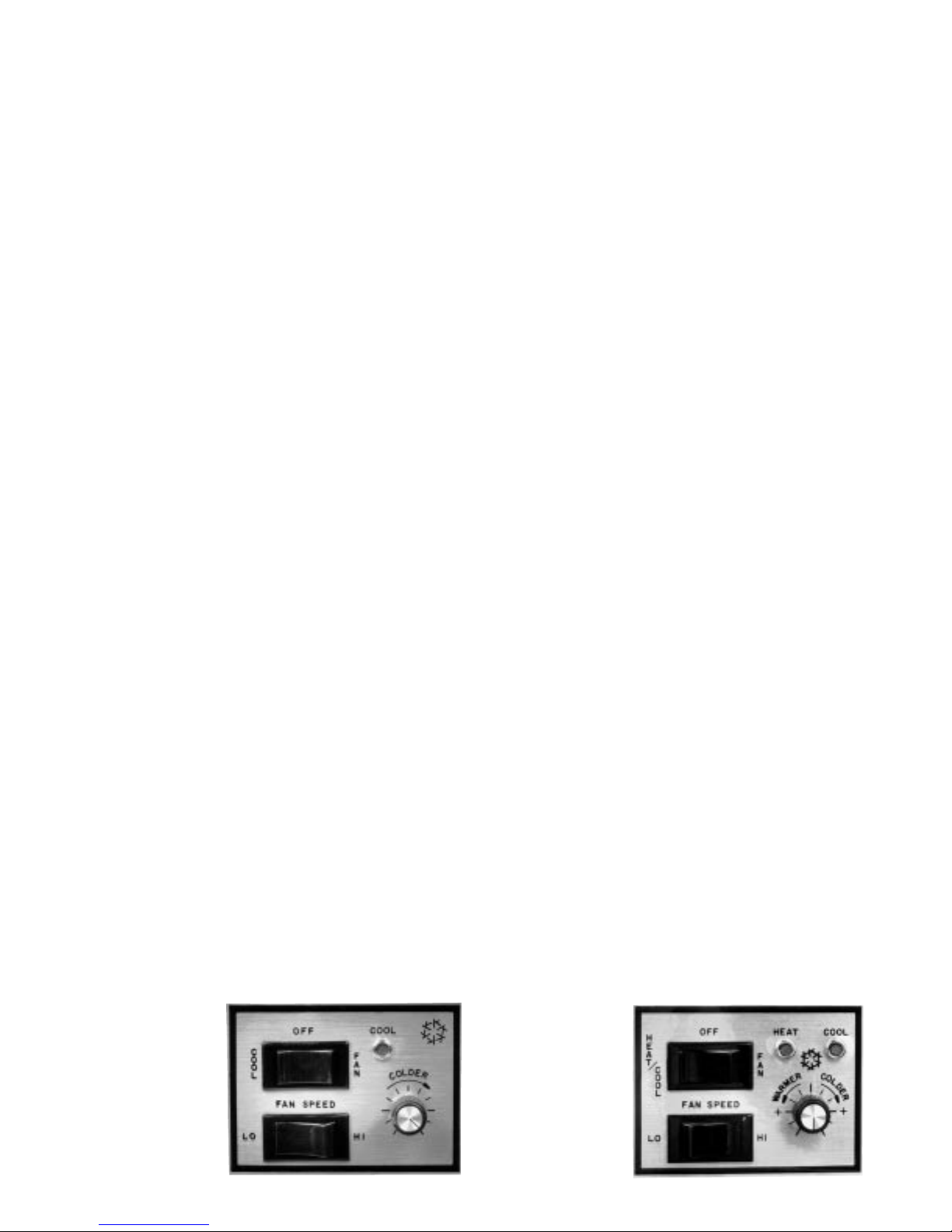
The three position rocker switch located in the control
panel has three functions:
1. It provides fan only operation when depressed to
right.
2. It turns the unit off when set in the center position.
3. It activates the cooling or heating mode when
depressed to left, depending on unit model and
thermostat setting.
The two position switch located under the three
position switch provides high fan speed when
depressed to the right, and low fan speed when
depressed to the left.
When illuminated, the blue light above the thermostat
indicates cooling and the amber light (on heat pumps
only) indicates heating.
Built-In Condensate Pump
Each unit contains a condensate pump for the positive
removal of evaporator condensate. The condensate
pump is capable of pumping against an 11 ft. head.
Condenser Coil
The water-cooled, tube-in tube type condenser coil is
designed for a maximum water side working pressure
of 400 PSI.
Safety Engineered
All units incorporate within the refrigeration system, a
high pressure switch for maximum safety of the
compressor. The cut-out pressure setting is 375 PSIG
± 3 PSIG. During the heating cycle of the heat pump
models, a freeze control sensor set at 37 ± 2°F
monitors the water temperature leaving the condenser
to cut-out the unit and protect the condenser from
freezing.
Reliable Controls
All models have self-contained thermostats to provide
the desired amount of cooling, which can be selected
by adjusting the thermostat to warmer or cooler. On
heat pump units, when the thermostat is set at the
desired position, the unit will automatically provide
heating or cooling, whichever is desired.
Filter
All units are equipped with 1/2" thick, washable,
aluminum mesh air filter located behind the front panel
that can easily be removed and cleaned. Just pull the
filter end cap tab at bottom of filter and slide out.
Discharge Air Grilles
The Koolette is equipped with three, the Kompac with
four, and the King Kompac with five 5" x 5", four-way
adjustable, plastic grilles located in the upper front
panel, enabling a variety of air flow possibilities. Lift
each black grille (approximately 3/4") and rotate to the
desired position. Release the grille and allow it to
return to the set position within the cabinet. By this
means, air flow can be positioned in any of four
directions.
4
KOLDWAVE KOMPAC SERIES (KOOLETTE, KOMPAC, AND KING KOMPAC)
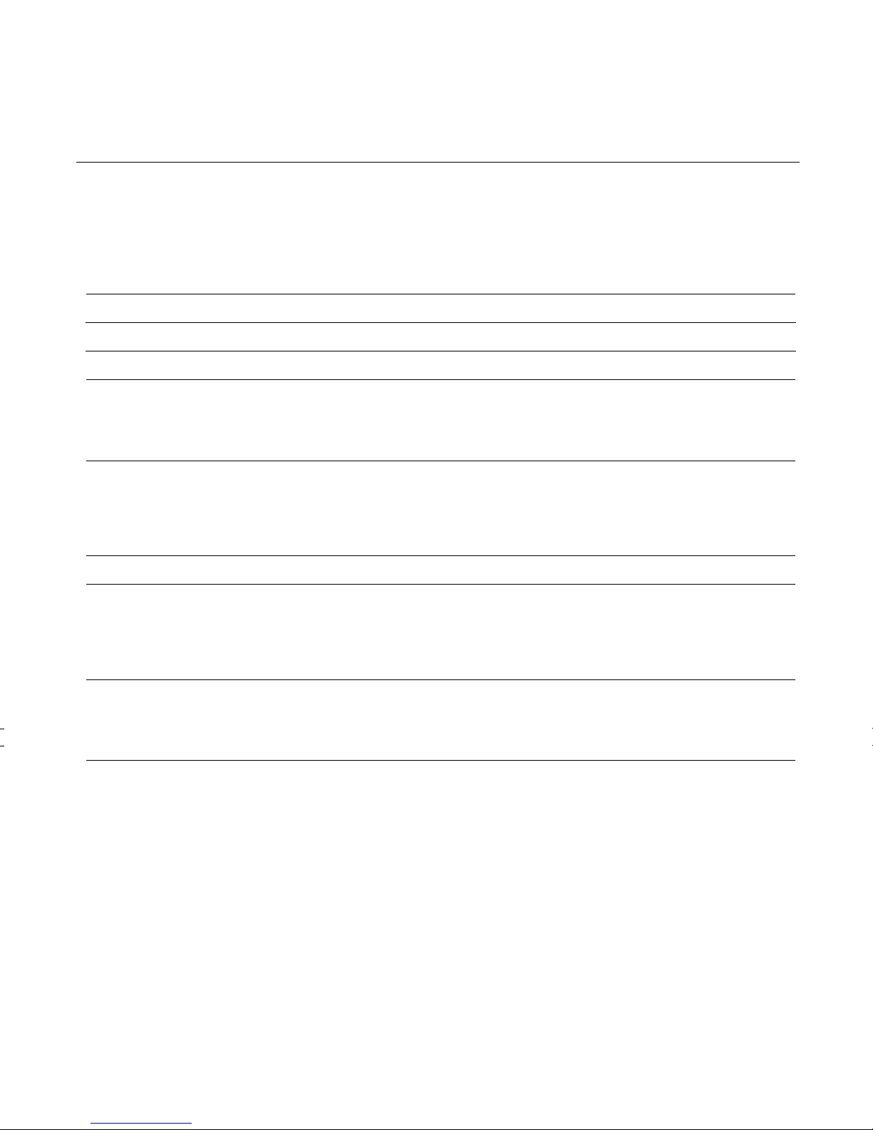
Service Cord
The six ft. long service cords employed in the Kompac
Series units have plug configurations and receptacle
requirements as shown in the chart below.
ELECTRICAL SERVICE PLUG CONFIGURATION
Conditioner
Model Plug Configuration Receptacle
2K07-14DB 15A - 125V
115V Nema 5 - 15P
2K16DB 20A - 125V
115V Nema 5 - 20P
2K10-26DB 20A - 250V
208/230V Nema 6-20P
Nema 5 - 15R
Nema 5 - 20 R
Nema 6 - 20R
OPTIONAL FEATURES
Hose Kit
When employing one of The 7′, 20′ or 40′ reinforced
plastic HK22 hose kits in applications with water
pressures exceeding 50 PSIG, a water pressure
reducing valve must be installed in the water supply
line prior to the hose kit; otherwise warranty of the
hose kit will be void. The water-out and condensate
lines of the three-section flexible plastic hose can be
fed to a sink or permanent drain. Additional hose kit
fittings and washers are provided to fit most water
faucets. When using a hose kit, avoid sharp corners
hot water pipes, and kinking or close bends to ensure
proper water flow of the supply and return lines.
Cupro-Nickel Condenser
When using chemicals to treat water in cooling tower
applications or when water contains process
contaminants, it is recommended that the air
conditioner be equipped with a 90/10 Naval Spec.
Cupro/nickel condenser.
High Pressure Water Valve
High pressure water regulating valves, designed for
use with up to 350 PSI water inlet pressure, are
available.
Treated Evaporator Coils
For air conditioning applications where airborne
contaminants are a problem, acrylic coated evaporator
coils are recommended to guard against pitting or
corrosion.
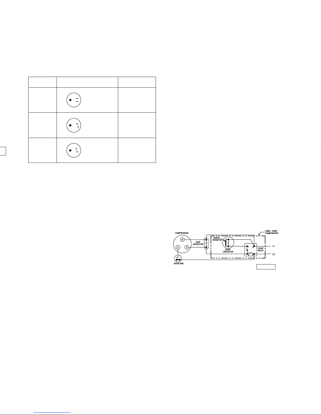
Hard Start Kit
A hard start kit consists of a start capacitor and
potential relay. The kit is available for all models when
they are expected to operate at low voltages and/or
ambient temperatures which drive up the equalization
pressure in the compressor. Compressors used by
Koldwave are designed to operate on 115 and 208/230
volts ± 10%.
Starting Component Wiring Diagram
0240019A
5
KOLDWAVE KOMPAC SERIES (KOOLETTE, KOMPAC, AND KING KOMPAC)
INSTALLATION INSTRUCTIONS
Before installing: Check the air conditioner for any
shipping damage. Air conditioners are thoroughly
inspected at the factory and carefully packed. If any
damage is evident, file a claim with the delivering
carrier immediately.
Electrical Requirements
Check the data plate on the back of the unit to make
certain that the proper power is available. Refer to the
“Specifications” section for voltage and fuse
requirements. Check for proper wall outlet as
described in “Standard Features”. Operating the unit
on improper voltages will void the warranty.
CAUTION: The use of an extension cord rated at
least 15 amps at 115 volts for (2K07-14D); 20 amps
at 115 volts for (2K16D); 20 amps for (2K10-26D) at
250 volts and with grounding-type attac hment plug,
and grounding-type connector (load fitting) may be
used.
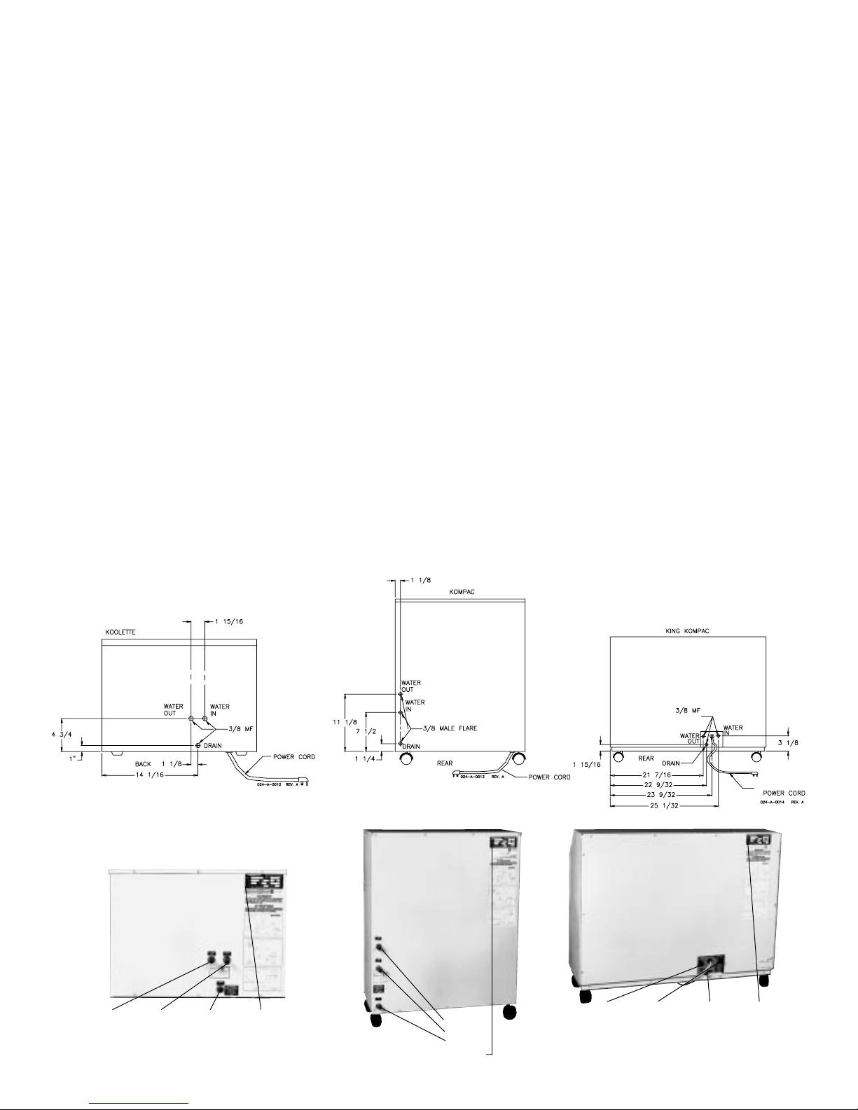
Water Fitting Location
Prior to placing the air conditioner in the desired
position, note the exact location of the water fittings on
the valve plate on the unit rear panel. Water lines
should be securely attached to water valve plate
fittings. Be sure the line attached to the water source is
also attached to the “WATER IN” connection of the
unit.
Refer to diagrams and photographs below when
installing unit.
Water Out Water In Drain Data Plate
Koolette Kompac King Kompac
6
Water Out
Water In
Drain
Data Plate
Water Out Water In Drain Data Plate
KOLDWAVE KOMPAC SERIES (KOOLETTE, KOMPAC, AND KING KOMPAC)
Conventional Installation
For proper installation, follow these simple steps:
A. Shut off cold water supply.
B. Install “T” between supply valve and faucet of cold
water line.
C. Connect water shut-off valve to branch of “T”.
D. Insert 3/8" pipe nipple in discharge end of water
shut-off valve.
E. Apply coupling over 3/8" pipe nipple and secure.
CHECKOUT OF UNIT OPERATION
Kompac Series air conditioners and heat pumps
provide cooling and heating,respectively. This is
accomplished by setting the operating controls on
either of the following panels:
Fan Only
Plug unit in. Depress the upper mode selector switch
to the right for fan only operation. Press down on the
two position switch located below the three position
switch to the right for high fan speed; to the left for low
fan speed.
Cooling Cycle
Depress the upper mode selector switch to the left
(cool) for cooling. Set the thermostat knob by turning it
clockwise, below the actual room dry bulb temperature
level. The blue-colored light located next to the upper
rocker switch on the panel will illuminate, indicating
cooling mode operation. Allow unit ot run with fan
speed set on high for twenty minutes, record
temperature of air entering the filter and temperature
of air leaving the air discharge grille. In a room
temperature of approximately 80°F dry bulb, air
coming from the grille should be approximately 15°F
cooler than the air going to the filter. This cycle
reduces the dry bulb temperature and lowers the wet
bulb temperature by condensing water on the cooling
coil surface. The condenser leaving water temperature
should be between 95-100°F if water flow adjusted
propertly.
Note: An alternate installation method can be
achieved by drilling a 5/16" diameter hole in the cold
water line and assembling a saddle valve to the line.
Complete installation by following steps “D” and
“E”.
Heating Cycle
Depress the upper mode selector switch to the left
(heat) for heating. Set the thermostat knob, by turning
it counterclockwise, above actual room dry bulb
temperature level. The amber-colored light located next
to the upper rocker switch on the panel will illuminate,
indicating heating mode operation. Allow unit to run
with fan speed set on high for twenty minutes, record
temperature of air entering the filter and temperature
of air leaving the air discharge grille. In a room
temperature of approximately 70°F dry bulb, air
coming from the grille should be approximately 30°F
warmer than the air going to the filter. The condenser
entering water temperature must not be lower than
50°F. The temperature of the water coming from the
“water out” fitting should be 7-8 degrees colder than
the water going into the unit.
Water temperatures described for cooling and heating
modes are based on units with pressure actuated
water regulating valves installed as standard
equipment at the factory.
Cooling Only
Control Panel
Cooling/Heating
Control Panel
7
KOLDWAVE KOMPAC SERIES (KOOLETTE, KOMPAC, AND KING KOMPAC)
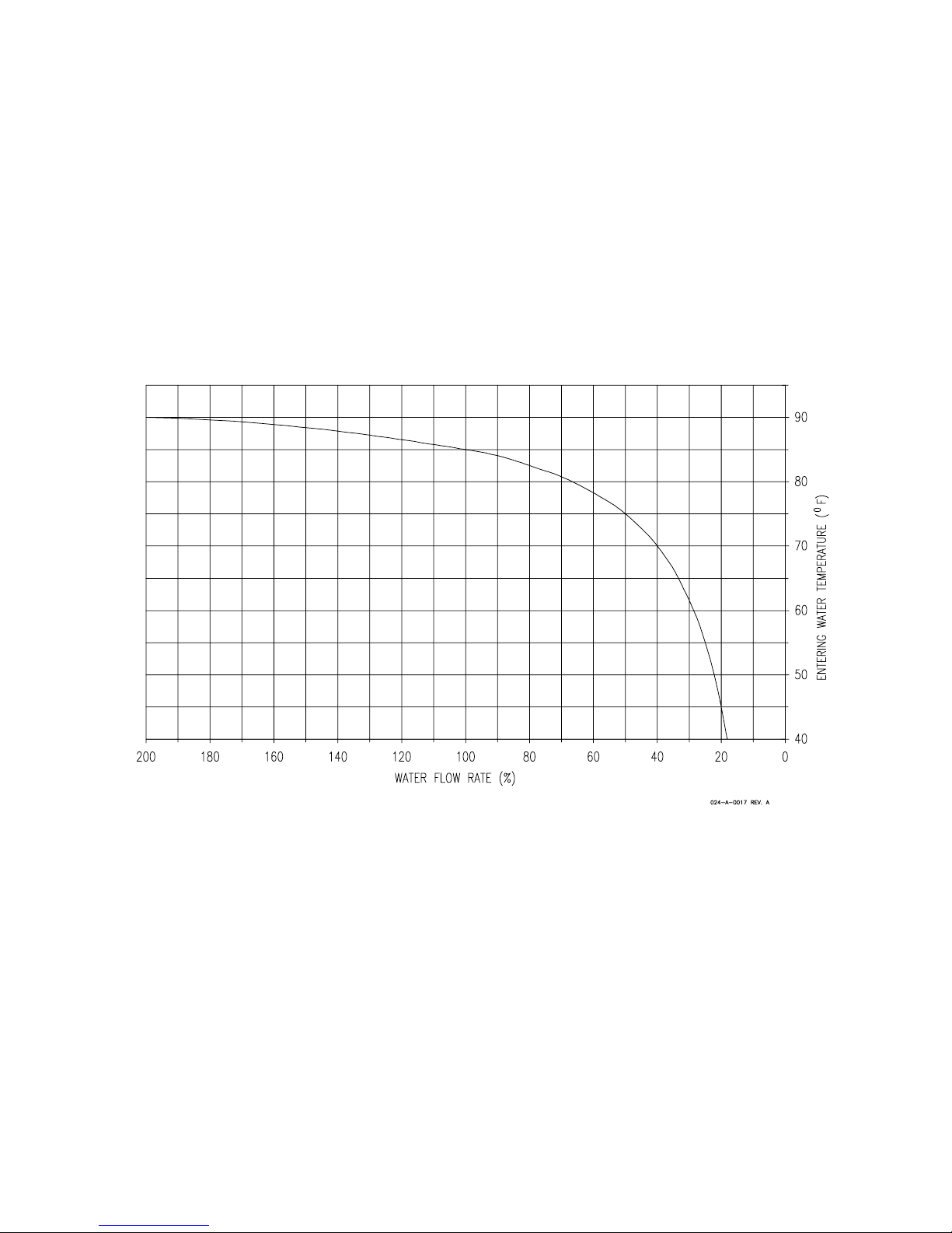
WATER FLOWS AT VARIOUS
ENTERING WATER TEMPERA TURES
The rated water flow rate at 85°F entering water
temperature (E.W.T.) is given in the specification chart
earlier in this manual. Water flow rates in that chart
will be significanly different from rated water flow at
other entering water temperatures. The variance from
rated water flow rate is found using the graph below.
Using your actual E.W.T., multiply the percentage by
the condenser flow rate at 85°F E.W.T. to obtain the
actual water flow rate required.
Water Flow Chart
For Example:
What is the actual condenser water flow rate at 50°F
E.W.T. (2K14D)?
1. The condenser water flow rate at 85°F E.W.T. is 3.0
G.P.M. from the Water Flow chart.
2. At 50°F E.W.T., the water flow rate percentage
would be 25% as seen on the graph.
3. Multiply .25 by 3.0 G.P.M. to get an actual water
flow rate of 0.75 G.P.M.
8
 Loading...