

Page 1
KOLD-DRAFT
CLASSIC
T-261 / T-264
®
KOLD-DRAFT
®
ICE CRUSHER
Installation & Operation Instructions
Ice Machine Products
1525 East Lake Road, Erie, PA 16511-1031
814/453-6761
FAX 814/455-6336
©2004 KDIndustries, Inc., Erie, PA U.S.A.
Printed in U.S.A. 3/04
508 1035 01
A Tradition of Excellence In Ice Equipment.
Page 2
INSTALLATION AND OPERATION INSTRUCTIONS
®
FOR KOLD-DRAFT
CHECK FOR FREIGHT DAMAGE BEFORE PROCEEDING: Even though damage to
the carton may not have been evident, check for hidden damage and contact freight
carrier immediately if necessary to file a claim.
THIS EQUIPMENT MUST BE INSTALLED IN COMPLIANCE WITH THE
APPLICABLE FEDERAL, STATE/PROVINCE AND/OR LOCAL PLUMBING,
ELECTRICAL AND HEALTH/SANITATION CODES AND REQUIREMENTS.
CAUTION:
RISK OF PERSONAL INJURY, PROPERTY DAMAGE, EQUIPMENT FAILURE
OR FIRE.
Refer all maintenance to qualified personnel.
Never operate this equipment with covers, panels or other parts removed or not
properly secured.
Warn all users to clean up spillage immediately, keep storage bin doors
closed, and report any apparent leakage or unusual sounds to maintenance
personnel.
T-261 & T264 ICE CRUSHERS
®
INSTALLATION
NOTE: Refer to ice cuber instructions before proceeding.
1. Position the ice storage bin maintaining the minimum clearances specified in the
cuber instructions.
Page 3
2. Level the bin with adjusters on legs, or by shimming if the bin is to sealed to the
floor. If gaps due to shims are greater than 1/8 inch, install a cove molding
around the bin bottom. Seal the bin or molding to the floor with NSF Certified
RTV sealant (Dow-Corning RTV 732 or equal).
3. Install gasketing on top of bin if required. Gasket material must be positioned so
that it extends to the outside edge of the perimeter of the crusher chassis when
the crusher is in place.
4. CAREFULLY lift the crusher out of the carton and place onto the gasketed bin.
Remove the front cover and note the alignment of the mounting holes in the
chassis if mounting means are provided on the bin. Follow the bin installation
instructions for securing the crusher to the bin. (NOTE: The selector knob must
be removed before the front cover can be removed.)
CAUTION:
RISK OF PERSONAL INJURY OR EQUIPMENT DAMAGE.
Use a suitable lifting means and be careful of sharp edges.
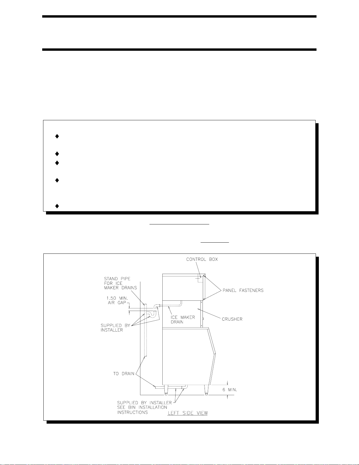
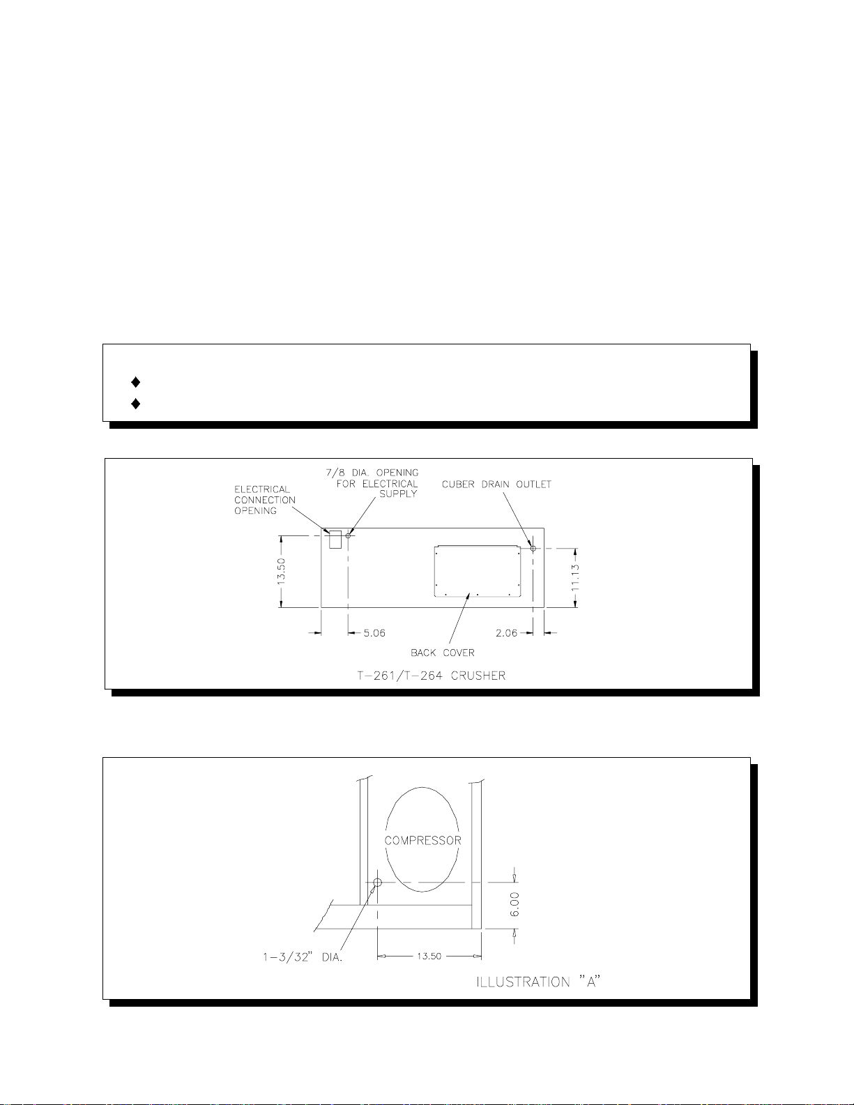
5. Electrical and drain locations are shown below. All dimensions are in inches.
6. If a knockout is not provided, punch an 1-3/32 inch dia. hole in the ice maker
condensing unit pan for the crusher control wiring. (See Illustration "A")
508 1035 01
- 2 -
Page 4

7. Install gasketing on top of crusher. (See Illustration "B")
8. Remove the cuber cabinet panels, lift and position cuber on top of gasketed
crusher and align mounting holes. Install cap screws, lockwashers and nuts.
(See Illustration "C") CAUTION: Support cuber until all fasteners are secured.
9. The crusher is designed to operate in conjunction with one or two
KOLD-DRAFT
®
cubers. Two motor control relay blocks are provided and a relay
coil must be installed for each cuber used. Each relay coil must have a voltage
rating matching the voltage of the ice cuber, regardless of the crusher motor
voltage. The relay coils are installed through the opening in the control box, by
the installer, and are ordered separately. A third relay is provided for controlling
one or two cubers with the same set of bin thermostats. This relay coil voltage
rating is matched to the crusher motor voltage and is provided with the crusher.
10.A dual safety switch system is employed in the crusher design to break the
circuit to the motor. If either the front panel of the crusher or the front panel of
the bottom ice maker is removed, a switch will open the motor circuit. The
crusher safety switch is mounted in the crusher control box. The ice maker
safety switch must be mounted by the installer. (See Illustration "D") If not
provided, locate and drill two 3/16 inch dia. holes in the ice maker lower front
rail. Mount the safety switch support with the #8-32 screws and nuts provided.
CAUTION:
The safety switches DO NOT de-energize all circuits in the crusher or any
circuits in the ice maker. Before cleaning or servicing this equipment,
disconnect all power supplies.
508 1035 01
- 3 -
Page 5

11.Install a grommet in the 1-3/32 inch dia. hole in the ice maker condensing unit
pan. Push the crusher control wire assemblies through the grommet into the ice
maker.
12.Connect the safety switch wires from the crusher to the "Common" and
"Normally Open" terminals of the cuber safety switch. (See Wiring Diagram)
13.Route the crusher control wires along the right side of the partition wall to a 7/8
inch hole located to the right of the contactor. Install a grommet in the hole and
push the wires through.
14.The bin thermostat in the cuber must be disabled and replaced by the two
thermostatic switches in the crusher. (See Wiring Diagram)
15.The crushed ice thermostat (left) cap tube is placed into the straight thermostat
tube holder. Push the cap tube into the flared end until the cap tube is visible at
the straight end. Install the tube holder into the hole in the motor platform directly
behind the crusher motor.
16.The cube ice thermostat (right) cap tube is placed into the bent thermostat tube
holder. Mount the tube holder as shown. (See Illustration "E") Tighten clamp
screws. Adjust thermostats to shut off the cuber approximately 1 minute after ice
contacts the tube holders.
CAUTION:
Route bin thermostat cap tubes away from moving parts.
508 1035 01
- 4 -
Page 6

INSTALLATION SPECIFICATIONS
The T-261 is wired, at the factory, for 100-120 volt 50/60 hz. operation.
The T-264 is wired for 200-240 volt 50/60 hz. operation.
CAUTION:
Risk of property damage, equipment failure or fire. Comply with all installation
specifications for safe operation.
Refer to equipment name plate data for current value and maximum fuse size. This unit
must be provided with a separate, properly protected circuit with no other loads. A
fused disconnect installed adjacent to the crusher is recommended (must be supplied
by installer), and may be required by local codes.
Crushers are intended for indoor use only with permanent connection to a field
electrical supply. All models are intended to be installed only in conjunction with
KOLD-DRAFT® cubers on KOLD-DRAFT® bins.
CRUSHER OPERATION
With the crusher knob in the "CRUSHED" position, ice falling from the cuber will be
directed by the selector plate through the crusher mechanism and deposited into the
left side of the bin.
The crusher motor is powered through a relay which is energized by the red circuit of
the ice maker. The selector knob must be in the "CRUSHED" position to close a switch
and complete the circuit to the motor. Additionally, the front panel safety switches must
be depressed (covers on) for motor operation.
With the crusher knob in the "CUBE" position, ice falling from the cuber will bypass the
crusher mechanism and be dumped into the right side of the bin. The crusher motor will
not be energized.
508 1035 01
- 5 -
Page 7

CRUSHER MAINTENANCE
Every 6 Months Minimum
CLEANING
CAUTION:
Risk of personal injury, equipment damage or contamination of the ice bin.
Do not use ammonia solutions or strong detergents in cleaning the crusher.
Never use appliance polishes, finish preservatives or cleaners in areas that
could contact ice.
Disconnect power before cleaning or servicing unit.
Always clean the ice maker first, following the ice maker cleaning instructions.
Remove all ice from the bin before starting the cleaning procedure.
Clean and sanitize storage bin last.
1. Remove ice maker panels, ice chute, drain pan, crusher front panel and belt
guard.
2. Wash interior with a solution of 2 tablespoons of baking soda per quart of clean
water (140 deg. F. max.). The crusher ice hopper can be accessed from the front
and left side of the ice cuber. Use a long handled brush to clean inside the
hopper, as crusher teeth can cause injury.
3. The bottom area of the crusher ice hopper can be accessed from inside the ice
bin. Use a long handled brush.
4. Wipe down internal cabinet walls with a cloth soaked in cleaning solution.
5. Rinse with clean tap water.
6. Sanitize all ice contact surfaces with a solution of 1 teaspoon 5-1/4% sodium
hypochlorite (chlorine bleach) per quart of clean tap water (minimum 100 PPM
free chlorine). A spray bottle will facilitate this process.
7. Pour the remaining solution into the crusher chute, slowly, while rotating the
cutter wheel by hand turning the pulley.
8. After adjusting and lubricating crusher (See following section), replace all
enclosure panels and connect the electrical supply.
9. Exterior surfaces may be cleaned by standard methods suitable to the stainless
steel finish.
ADJUSTMENT AND LUBRICATION
1. Oil the crusher motor (if ports are provided) and grease the shaft bearings. (Do
not over-lubricate)
2. Check the belt and pulleys for excessive wear. Adjust the belt tension to deflect
1/4 inch with two pounds applied to the center of the span.
3. Tighten any loose set screws, machine screws, nuts and electrical connections.
508 1035 01
- 6 -
Page 8

508 1035 01
- 7 -
 Loading...