

Page 1
KOLD-DRAFT
CLASSIC
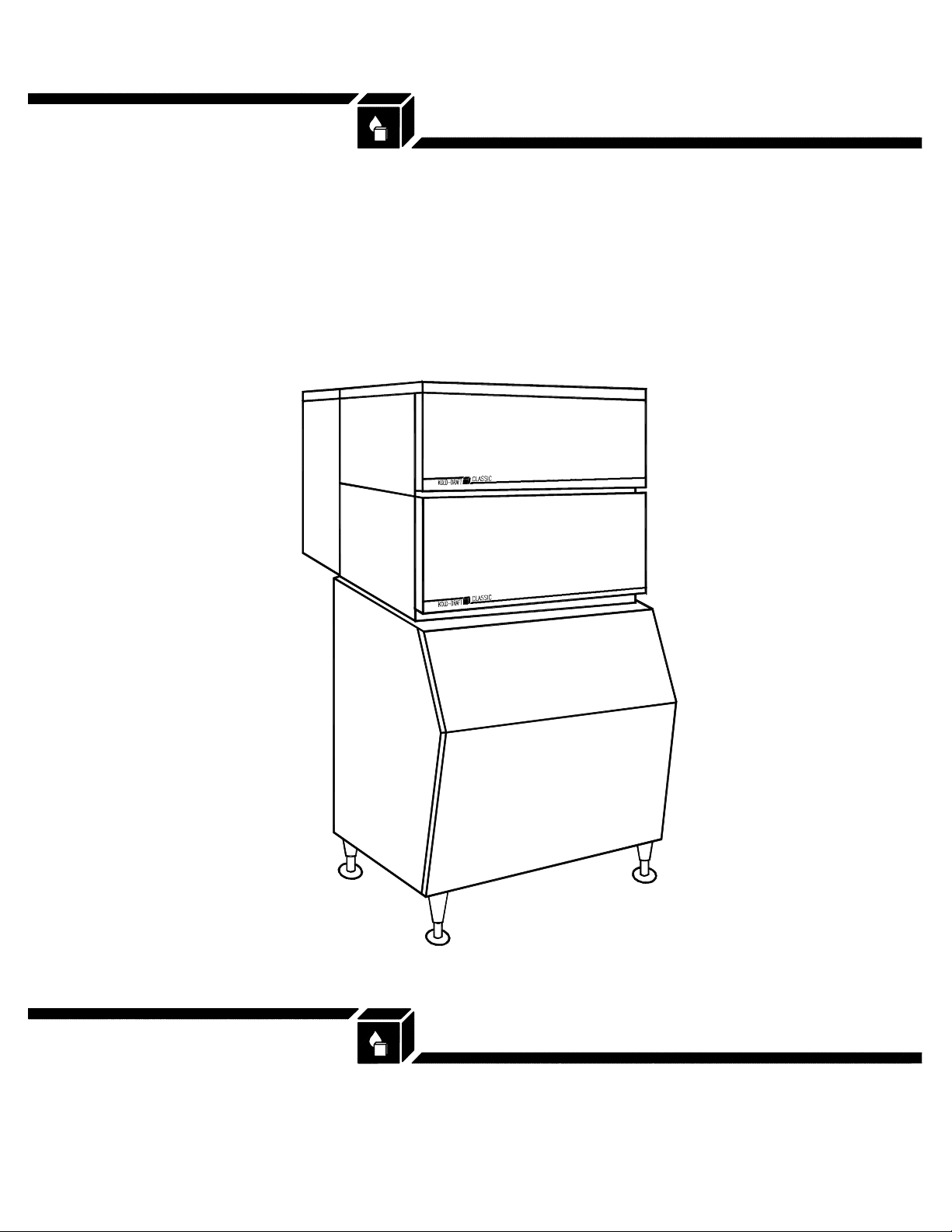
MGB654A
KOLD-DRAFT
Ice Machine Products
®
Air Cooled Marine Cuber
with Manifold
Installation Instructions
®
1525 East Lake Road, Erie, PA 16511-1088
814/453-6761
FAX 814/455-6336
©2004 KDIndustries, Inc., Erie, PA U.S.A.
Printed in U.S.A. 3/04
508 1063 01
A Tradition of E xcellence I n Ice Equipment.
Page 2
INSTALLATION AND OPERATION INSTRUCTIONS
FOR
KOLD-DRAFT
MARINE
ICE
CUBERS
®
CHECK FOR FREIGHT DAMAGE BEFORE PROCEEDING: Even though damage to
the carton may not have been evident, check for hidden damage and contact freight
carrier immediately if necessary to file a claim.
THIS EQUIPMENT MUST BE INSTALLED IN COMPLIANCE WITH THE
APPLICABLE FEDERAL, STATE/PROVINCE, AND/OR LOCAL PLUMBING,
CAUTION:
{
RISK OF PERSONAL INJURY, PROPERTY DAMAGE, EQUIPMENT
FAILURE, OR FIRE.
{
Refer all maintenance to qualified personnel .
{
Never operate this equipment with covers, panels, or other parts removed
or not properly secured.
{
Warn all users to clean up spillage immediately, keep storage bin doors closed,
and report any apparent leakage or unusual sounds to responsible
maintenance personnel.
ELECTRICAL, AND HEALTH/SANITATION CODES AND REQUIREMENTS.
INSTALLATION
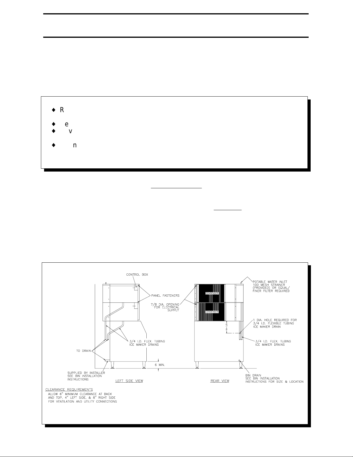
1. Position the ice storage bin so that the following minimum clearances will be
available around the i ce maker for ventilati on and utility connections:
REAR (beyond condenser if protruding from cabinet) and TOP: 6 inches
RIGHT SIDE: 8 inches
LEFT SIDE : 4 inches
508106301
--
Page 3
2. Level the bin with adjusters on legs, or by shimmi ng if the bin is to be seal ed to
the floor. If gaps due to shi ms are greater than 1/8 inch, instal l a cove molding
around the bin bottom. Seal the bin or molding to the floor with NSF Certified
RTV sealant (Dow-Corning RTV 732 or equal).
3. Remove the cuber cabinet TOP panel as follows:
Lift from the front and pull forward until the rear clip is disengaged from the
chassis.
4. CAREFULLY lift the cuber out of the carton and onto the floor.
CAUTION:
{
RISK OF PERSONAL INJURY OR EQUIPMENT DAMAGE.
{
Use a suitable lifting means and be careful of sharp edges.
5. Remove the remaining cuber cabinet panels as follows:
FRONT: Remove the (5) screws at the bottom and front-sides, pull forward.
SIDES : Pull forward and lift to disengage the clips from the chassis.
NOTE: When re-installing the panels, be sure that the screws engage the TOP
panel.
6. Remove the ice deflectors, ice chutes and drain pans. Drain tubes are packed
with the drain pans.
7. Install gasketing on top of bin if required. Gasket material must be positioned
so that it extends to the outside edge of the perimeter of the cuber chassis when
the cuber is in place.
8. CAREFULLY place the cuber onto the gasketed bin, noti ng the al i gnment of the
mounting holes in the chassis if mounting means are provided on the bin.
Follow the bin installation instructions for securing the cuber to the bin.
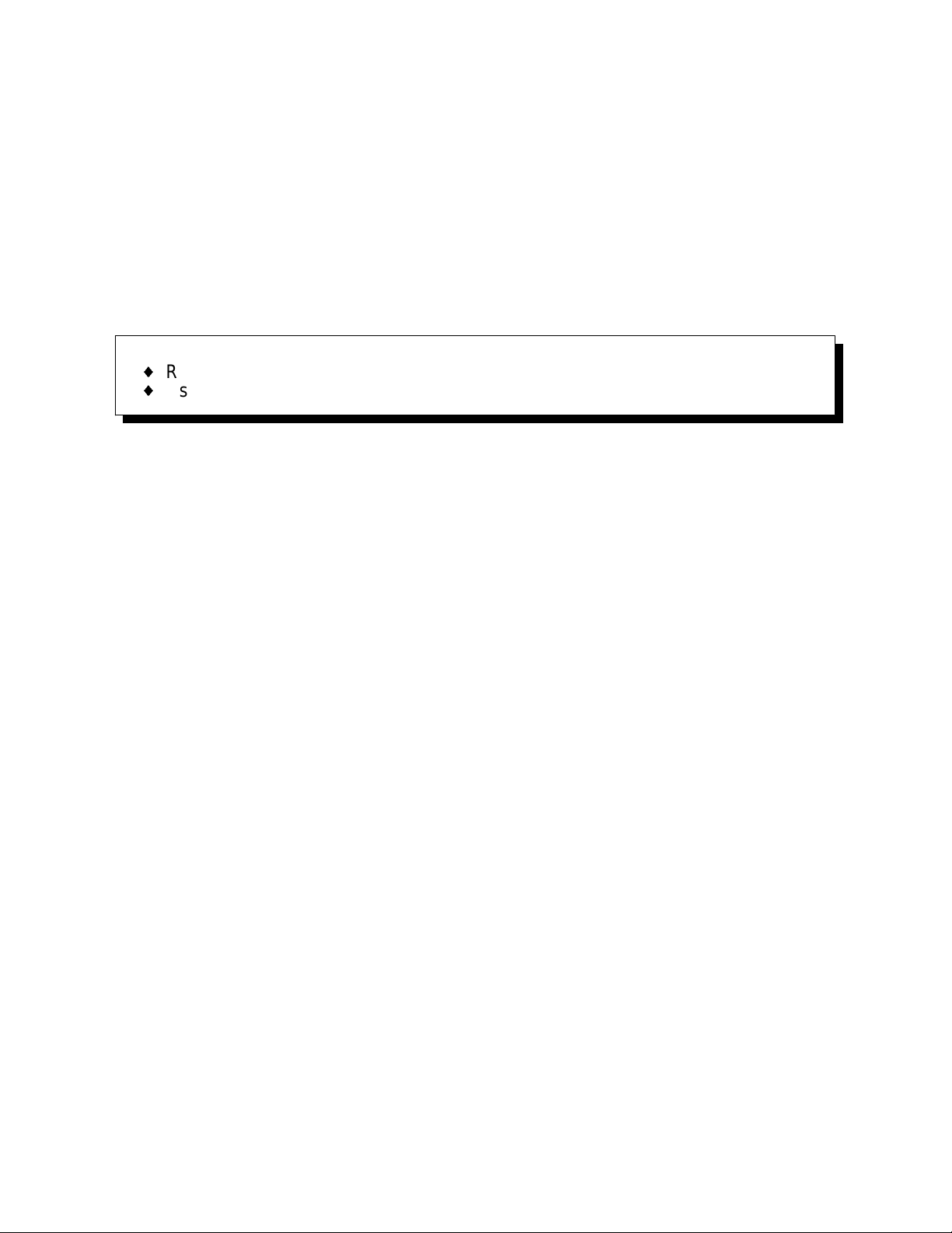
9. Install the drain pans, ice chutes and ice deflectors. Route the drain tubes
through the rear of the bin and the back of the lower ice machine, and clamp the
tubing to the drain pan nippl es.
508106301
-2-
Page 4
10. Typical drain tubi ng shown on the foll owing drawing.
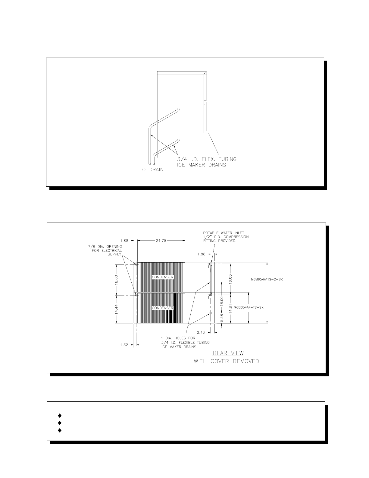
11. Electrical, water and drain locations are shown on the following drawing: All
dimensions are in inches.
12. Purge the potable water supply line.
WARNING:
{ RISK OF CONTAMINATION OF ICE IN THE BIN.
{ Provide separate, unconnected drains for the ice maker and the bin.
{ Consult local codes for sui table connections to the ship drains.
508106301
-3-
Page 5
13. Remove the water plate shipping strap(s).
ICE MAKER
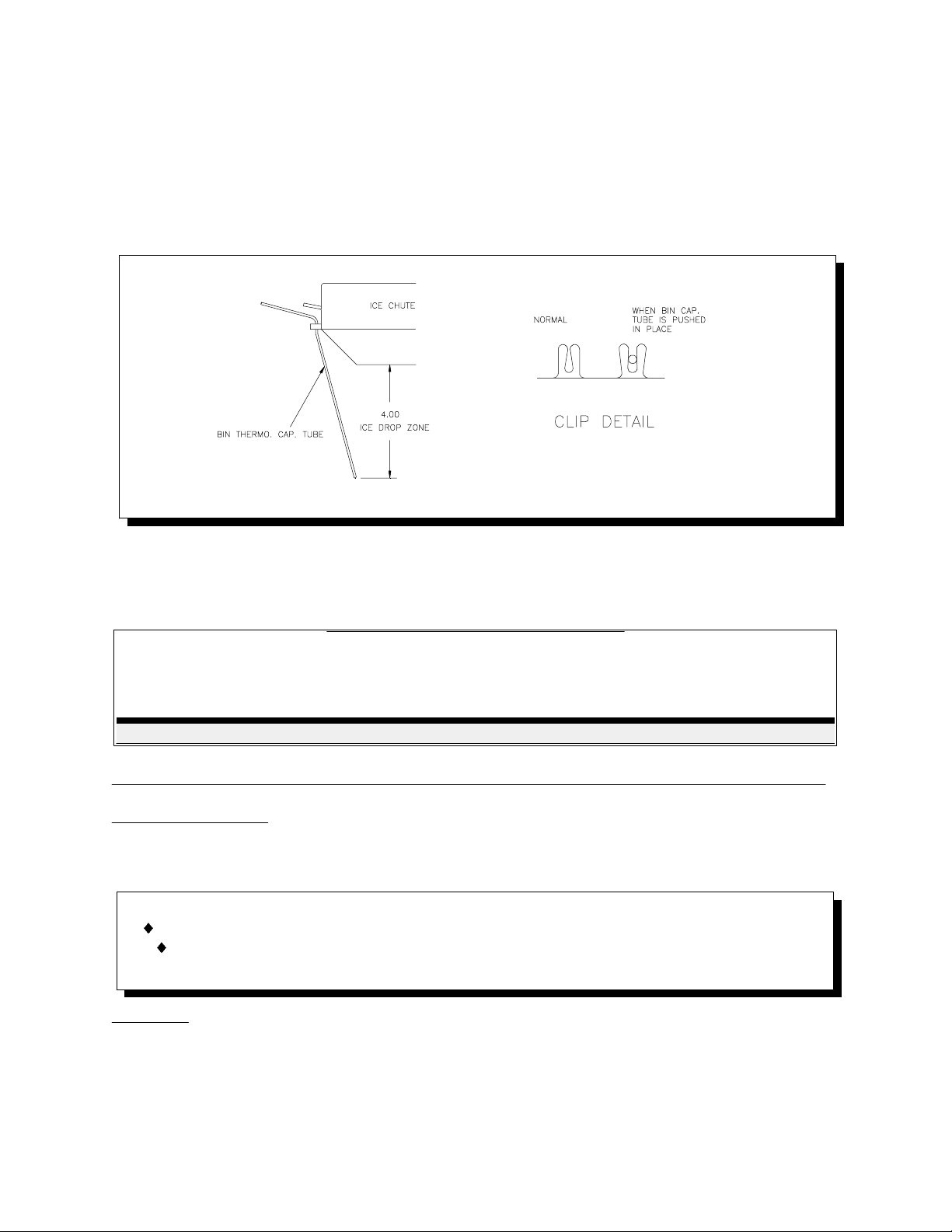
14. Route the bin thermostat capillary tube through the grommet in the compressor
compartment wall and under the ice chute. See the diagram and notes
following for location and securi ng of the capillary tube. The capillary tube clips
will be toward the drain pan when properly installed.
15. If start-up will not occur immediately, secure all cuber cabinet panels now.
INSTALLATION SPECIFICATIONS
CONDENSER
COOLANT
(COMP)
SUPPLY DISCHARGE
- -3/41/2 20 3018208-230/60/1MGB654A
ELECTRICAL
SUPPLYMODEL
MINIMUM
CIRCUIT
AMPACITY
FUSE / HACR
BREAKER SIZE
(AMPS)
NORMAL MAXIMUM
WATER
INLET SIZE
(COMP)
DRAIN SIZE
(ID)
READ THE FOLLOWING NOTES CAREFULLY PRIOR TO MAKING CONNECTIONS
Voltage tolerances: Nominal No-load MAXIMUM Full-load MINIMUM
208-230 252 198
CAUTION:
{ RISK OF PROPERTY DAMAGE, EQUIPMENT FAILURE OR FIRE
{ Failure to comply with all installation specifications and instructions may
cause
Ampacity: Minimum ampaci ty does not indicate typical running current value. Refer to
equipment NAME PLATE data. Use mi nimum ampacity value for sizing branch circuit
conductors up to 25 feet length. For conductor length over 25 feet up to 100 feet,
increase 1 AWG size. Over 100 feet requires 2 or more AWG size increase.
508106301
-4-
Page 6

Branch circuit protection: Proper protection must be provided by either fuse(s) or
HACR type circuit breaker(s). Each ice maker must be provided with a separately
protected circuit with no other load(s). A fused disconnect installed adjacent to each
ice maker is recommended (must be supplied by the installer), and may be required by
local codes. NORMAL protector size is based on rated vol tage and operati on at lower
than extreme temperature limits. W hen branch circuit conductors are sized to permi t,
increasing the protector size (up to the specified maximum) may avoid nuisance
protector opening under harsh operating conditi ons.
Water supply: Minimum 30 psig supply pressure while the ice maker is filling is
required. Maximum supply pressure is 100 psig. The water fill flow rate is 1 GPM for
each MGB654W machine. Backflow/backsiphonage protection is provided by an
internal air gap (accepted by NSF). If additional protection is requi red by local codes
or authorities, any device(s) and installation of the same, including specification and
cost, are the responsibility of the installation specifier.
Ice maker drain: The size of the gravity drain for the ice maker purge and rinse water
must not be reduced. Individual drains from stacked ice makers may be discharged
into a standpipe or manifold with a minimum 1-1/2 inch air gap at each ice maker
connection.
All models are intended FOR INDOOR USE ONLY with PERMANENT CONNECTION
TO THE F IELD ELECTRICAL SUPPLY.
Other operating condition requirements:
Ice maker ambient air temperature: MINIMUM 45°F.; MAXIMUM 90°F.
Potable water and condenser liquid supply:
Temperature: MINIMUM 45°F.; MAXIMUM 90°F.
Pressure: MINIMUM 30 psig; MAXIMUM 100 psig*
*If regulator is used, recommended setting is 30 to 50 psig.
KOLD-DRAFT supports all efforts to preserve our environment.
Since comme rcial refrigerants are suspected of being harmful
to the environment, NEVER VENT REFRIGERANT INTO THE
ATMOSPHERE.
508106301
-5-
Page 7

START-UP INSTRUCTIONS
WATER LEVELS, CYCLE TIMES, AND REFRIGERANT CHARGES
PARAMETER MGB654AC/HK
--------------------------------------------------------------------------------------------------------------Water fill level (Top of tank to level in control tube) 2-3/4"
*Approximate cycle time, min. 21
Refrigerant charge (R-404a), oz. 30
Approximate harvest weight, lb. 7.1
* Values are at 90°F. air/70°F. water temperatures with cuber adjusted to produce
fully-formed ice. Greater capacity can be obtained by reducing the water fill level
(lowering the high-level probe) to produce i ce with larger dimples. A slight adjustment
of the probe will result in a noticeable effect on dimple size. The control stream will not
rise over the dam with lower water fill levels than indicated above.
CAUTION: REFRIGERANT CHARGES MUST BE ACCURATELY WEIGHED.
Consult the specification and troubleshooting guide if variations from the following
description of operation are noti ced:
1. Remove the top and front cabinet panels.
2. Be sure that the "ICE-OFF-WASH" switch is in the center (OFF) position.
3. Turn on supply water and power. Check for leaks in water/liquid supply
connections.
4. Be sure that pump hoses are connected, then put about one pi nt of clean tap
water into the circulation system to lubricate the pump seal.
5. Move the "ICE-OFF-WASH" switch to the right "WASH" position and observe
the water fill cycle and the pump running. If all water distributor holes do not
produce full streams and the appearance of air i s evident i n the tube, pi nch the
plastic tube connected to the water solenoid valve outlet while water is running
until the streams are full all the way across the distributor tube. W ater fill is
complete when the water in the liquid level control tube reaches the high-level
probe. At this time observe that the water shuts off and that there are no water
leaks (dripping i nto the drain pan).
6. Pull the right end of the water plate down, stretching the springs until the pump
stops, and hold until the pump does not re-start when released. The water plate
will open fully to dump the batch of water previously taken in, then close
immediately. The water plate should stop when it is fully closed, and the water
fill cycle will repeat.
508106301
-6-
Page 8

7. After the water fill is complete, move the "ICE-OFF-WASH" switch to the left
"ICE" position and observe that the compressor starts, and the water pump
continues to run. T he refrigeration system operation should be checked during
the first few cycles, and any adjustments should be made at this time. Consult
the "adjustments" section in the service manual. Initial ice making cycles may
exhibit super-cooling of the circulating water so that ice crystals form in the
circulating water ("slush"), possibly stopping the flow momentarily. If water
goes over the control stream dam when circulation resumes after two (2) cycles
AND with all skin panels installed, consult the Factory.
8. Test the bin thermostats by holding some ice against the capillary tubes. If
necessary, adjust the thermostats so that the ice makers shut off within 30
seconds after ice contacts the capillary tubes.
9. Be sure that the drain pans ice chutes and deflectors are in place, and that the
electrical control box covers are secured, then replace the cabinet panels
(skins). Start with the SIDE panels, then the FRONT panel, secure the FRONT
panel with (3) screws along the bottom edge, replace the TOP panel and finally
secure all the panels with (2) screws in the TOP-SIDES of the machine.
10. Discard ice from start-up cycles, then clean and sanitize the bin following the
instructions provided with the bin.
11. Complete and mail the Registration Certificate and leave this manual with the
owner/user. Emphasize the "CAUTION: RISK OF PERSONAL INJURY..."
NOTICE ON THE FRONT PAGE, and the importance of the PREVENTATIVE
MAINTENANCE recommendations below.
PREVENTATIVE MAINTENANCE
CLEANING: Usually at 3 to 6 month intervals, depending on water conditions.
INSPECTIONS: During cleaning - at least twice a year.
SERVICE: All such equi pment will require service at some time. Service requirements
will be minimized with faithful preventative maintenance including good housekeeping
at the installation site. A CALL FOR SERVICE AS SOON AS A POSSIBLE PROBLEM
IS NOTICED MAY AVOID EXTENSIVE REPAIRS.
508106301
-7-
Page 9

ICE CUBER CLEANING INST RUCTIONS
CAUTION:
{ RISK OF PERSONAL INJURY OR PROPERTY DAMAGE.
{ Do not use ammonia solutions in cl eaning any part of the ice maker.
{ Do not mix ice machine cleaner and sanitizer together.
{ Use rubber gloves, eye protection and an apron.
{ Clean up splashes or spillage immediately.
{ Follow these instructions exactly.
1. Mix one bag of KOLD-DRAFT ice machine cleaner (55R-01000-B) in two (2)
quarts of clean, warm water (180°F. MAX.) for each evaporator/water plate
assembly to be cleaned.
2. If the cuber is operating, wait until a harvest cycle occurs then trip the
"ICE-OFF-WASH" switch to "WASH" as soon as the water plate begins to close.
3. Empty all ice from the storage bin and shut off other ice makers on the same
bin.
4. After the water fill is completed, switch the "ICE-OFF-WASH" to "OFF". While
pinching water level control hose, carefully remove the water level control tube
from the cap. HOLD T HE TUBE HIGH ENOUGH SO THAT THE TUBE DOES
NOT OVERFLOW. Release the hose and pour about hal f of the mixed cleaner
into the tube. Replace the tube on the cap, while pinching water level control
hose, then pour the remaining cleaner into the control stream box.
5. Switch the "ICE-OFF-WASH" to "WASH" and allow the cleaner to circulate for
approximately 15 mi nutes, then pull the right side of the water plate down until
the pump stops and hold it until the pump will not re-start when released.
6. The water plate will open and dump the cleaner then close immediately, and the
water system will refill. Repeat this dumping and refilling three (3) times to rinse
out all of the cleaning solution.
7. Mix a sanitizing soluti on of two (2) oz. 5-1/4% sodium hypochlorite (household
bleach, or equivalent) and one (1) quart of cl ean water.
8. As in step #4, pour about half of the sanitizing solution into the water level
control tube and the remaining sanitizer into the control stream box.
9. Allow the sanitizing solution to circulate AT LEAST 15 MINUTES, then dump
and rinse two (2) times as described above. If necessary, reset the water level
probes to the proper levels.
10. While the cleaning and sanitizing solutions are circulating, clean, rinse, and
sanitize all accessible parts of the ice-making compartment of the cuber with
clean cloths. Use a cleaning solution of 8 tablespoons (1/2 cup) baking soda
per gallon of warm water, and a sanitizing sol uti on of no less than 1 teaspoonful
(5 ml) 5-1/4% sodium hypochlorite per quart of clean water.
11. After cleaning has been completed, trip the "ICE-OFF-WASH" switch to "ICE"
and check to be sure that the cuber is operati ng properly, parti cularly the water
level probes. Then re-assemble and secure all cabinet enclosure panels.
508106301
-8-
Page 10

ICE CUBER CLEANING INST RUCTIONS
ICE BIN CLEANING IN STRUCTIONS
The bin should be cleaned periodicall y. If bin drain has any horizontal run, remove ice
from left side of bin and fl ush with two quarts of hot water monthly. (Long drain lines
should be flushed weekly.)
1. Clean exterior of bin frequently.
2. To clean the interior, follow instructions provided with bin.
3. Empty the storage area and disconnect the electrical power supply to the ice
maker(s).
4. Remove the ice maker inspection panel, top, left and right end panels, and
drain pan. Sliding bin doors may be removed by lifting them up, then pul ling out
from the bottom.
5. When cleaning the ice maker, follow the ice maker cleaning instructions and
clean the bin last.
6. Replace all enclosure panels before re-connecting the electrical supply.
CAUTION:
{ RISK OF PERSONAL INJURY, EQUIPMENT DAMAGE OR CONTAMINATION
OF THE ICE BIN.
{ Do not use ammonia solutions or strong detergents in cl eaning any part of the
ice maker or bin.
{ Never use appliance polishers or other finish preservatives or cleaners in ice
storage areas.
WINTER CONDITIONING
Ice cubers that are idle in the winter months require preparation to prevent damage
from freezing. The following procedure shoul d i nsure the safety of the machine so that
it can be started easily the following year.
1. Shut off and detach the water supply to the Ice Cuber.
2. If the cuber contains a water-cooled condenser, the cuber must be running
while air is introduced through the condenser water inlet connection to blow
water out of the condenser coils.
3. The machine should then be run into defrost to drai n the water tank and the air
blown into the water inlet to blow out the water solenoid.
508106301
-9-
Page 11

MARINE MULTIPLEXING INSTRUCTIONS
{ Use a suitable lifting means and be careful of sharp edges.
STACKING ADDITIONAL UNITS, IF REQUIRED
CAUTION:
{ RISK OF PERSONAL INJURY, PROPERTY DAMAGE, EQUIPMENT
FAILURE OR FIRE.
{ Refer all maintenance to qualified personnel.
{ Never operate this equipment with covers, panels or other parts removed or
not properly secured.
1. Remove cabinet panels from upper and lower ice makers.
2. Mount support clips on top side flanges of lower ice maker frame and position
so the clip holes are aligned with the hol es in the frame. (See Illustration "A")
The lower flange of the front support clips must slide into the space between the
top side flange of the ice maker and the top flange of the electrical box.
508106301
-10-
Page 12

3.Apply gasket supplied with stacking kit to lower ice maker frame and cut to fit.
(See Illustration "B") Place gasket over the support clips already in position and
pierce the gasket where it covers the mounting holes.
508106301
-11-
Page 13

508106301
-12-
Page 14

508106301
-13-
Page 15

4. Position upper ice maker on lower unit and align mounting holes. Install cap
screws, lock washers and nuts. (See Illustration "A") CAUTION: Support upper
unit until all fasteners are secured.
5. Install the upper i ce maker drain pan and ice chute. Connect the drain hose to
the drain pan and route the drain hose through the rear of the lower ice maker.
6. Route upper ice maker bin thermostat capillary tube down to the lower ice
maker chute opening for positioning. Keep capillary tube toward front of
partition wall out of the path of falling ice. Note- For all machines stacked
above two high, a bin thermostat with a longer capillary tube is required.
Contact the factory for more information.
7. Install the side cabinet panels. Follow start-up instructions, included with ice
maker, to complete installation.
508106301
-14-
 Loading...