

Page 1
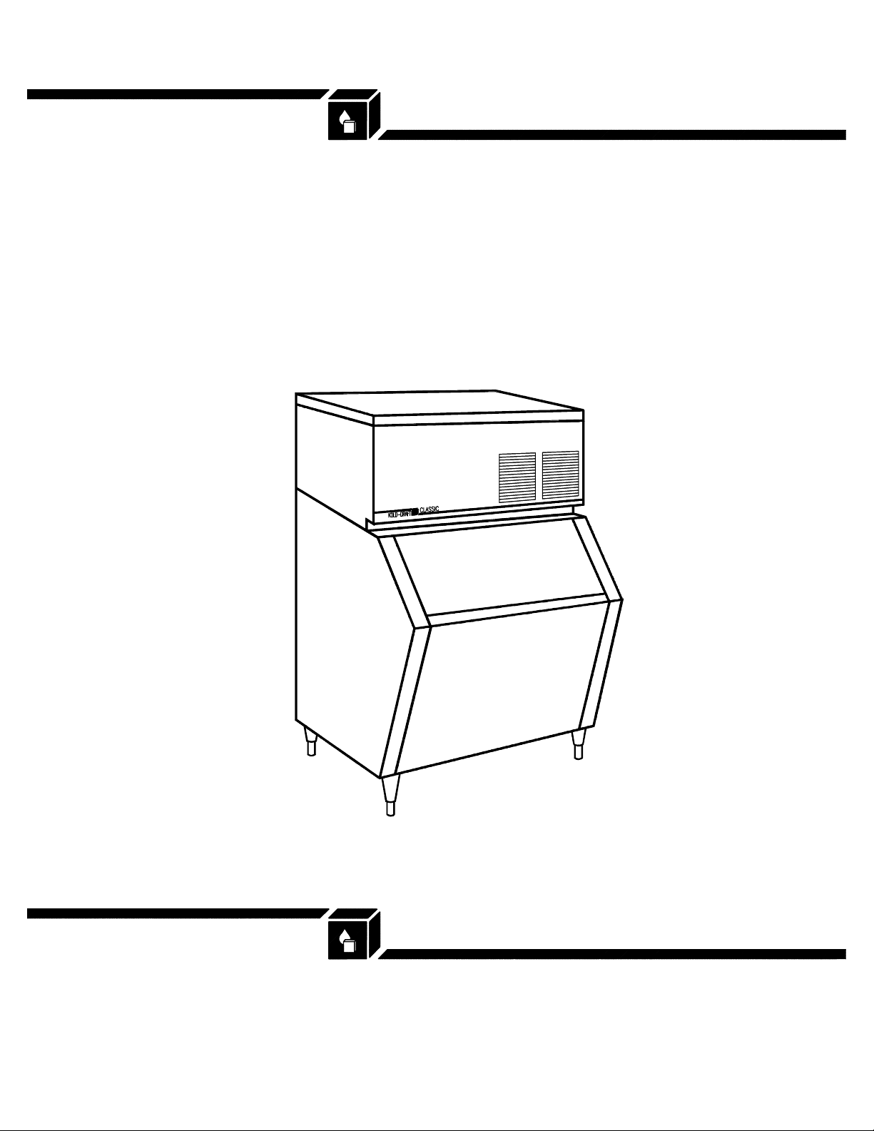
KOLD-DRAFT
CLASSIC
GB/GT/T-250
K
OLD-DRAFT
Ice Machine Products
®
T-260/AKD
Service and Parts Manual
1525 East Lake Road, Erie, PA 16511-1088
814/453-6761
FAX 814/455-6336
©2004 KDIndustries, Inc., Erie, PA U.S.A.
Printed in U.S.A. 5/07
LIT-09502 Rev.4/07
A Tradition of Excellence In Ice Equipment.
Page 2

Page No.
Table of Contents, 3/02
Table of Contents, CLASSIC Models, 5/03 printing ....................1
Key to CLASSIC Cuber Model Numbers .............................2
CLASSIC Cuber Installation Specifications ..........................3
CLASSIC Cuber Installation Guidelines ..............................5
General Information .............................................. 11
Preventive Maintenance ..........................................12
GB & GT CLASSIC Cuber Installation Instructions ....................14
CLASSIC Cuber Start-up Instructions ...............................19
Chart of Refrigerant Operating Pressures, Ice Cube Sizes and Weights 20
GB Multiplexing (Stacking) Instructions .............................21
GT3XX Multiplexing (Stacking) Instructions ..........................25
Operational Components, CLASSIC Cubers ..........................32
Controls and Adjustments, CLASSIC Cubers ......................... 37
Sequence of Operation, CLASSIC Cubers ...........................42
Service and Troubleshooting, CLASSIC Cubers:
Actuator Motor ...............................................46
Water Plate ..................................................57
Liquid Level Controller .........................................59
Cube Quality .................................................60
Compressor Charts, CLASSIC Cubers ..............................62
Wiring Diagrams, CLASSIC Cuber (Jan. '92 through Feb. '96) ........... 68
Wiring Diagrams, CLASSIC Cuber (March '96 through Sept. '97) .........77
Wiring Diagrams, CLASSIC Cuber (Oct. '97 and later) .................. 81
T-25X/T-26X Crusher Installation Instructions .........................95
T-25X/T-26X Crusher Installation Specifications .......................99
T-25X/T-26X Crusher Preventative Maintenance ......................100
AKD-125 Dispenser Installation Instructions ........................101
AKD-125 Dispenser Installation Specifications ......................104
AKD-125 Dispenser Preventative Maintenance ...................... 105
Wiring Diagrams, T-250/T-251 .....................................106
Wiring Diagrams, AKD-125 ........................................107
Parts List-Pictorial, CLASSIC Cubers ...............................108
Parts List-Pictorial, T-25X/T-26X/AKD-125 ........................... 139
Parts List-Numerical, CLASSIC Models ..............................140
Date Code ......................................................150
Rev:3/02 Kold-Draft® Service & Parts Manual
- 1 -
Page 3
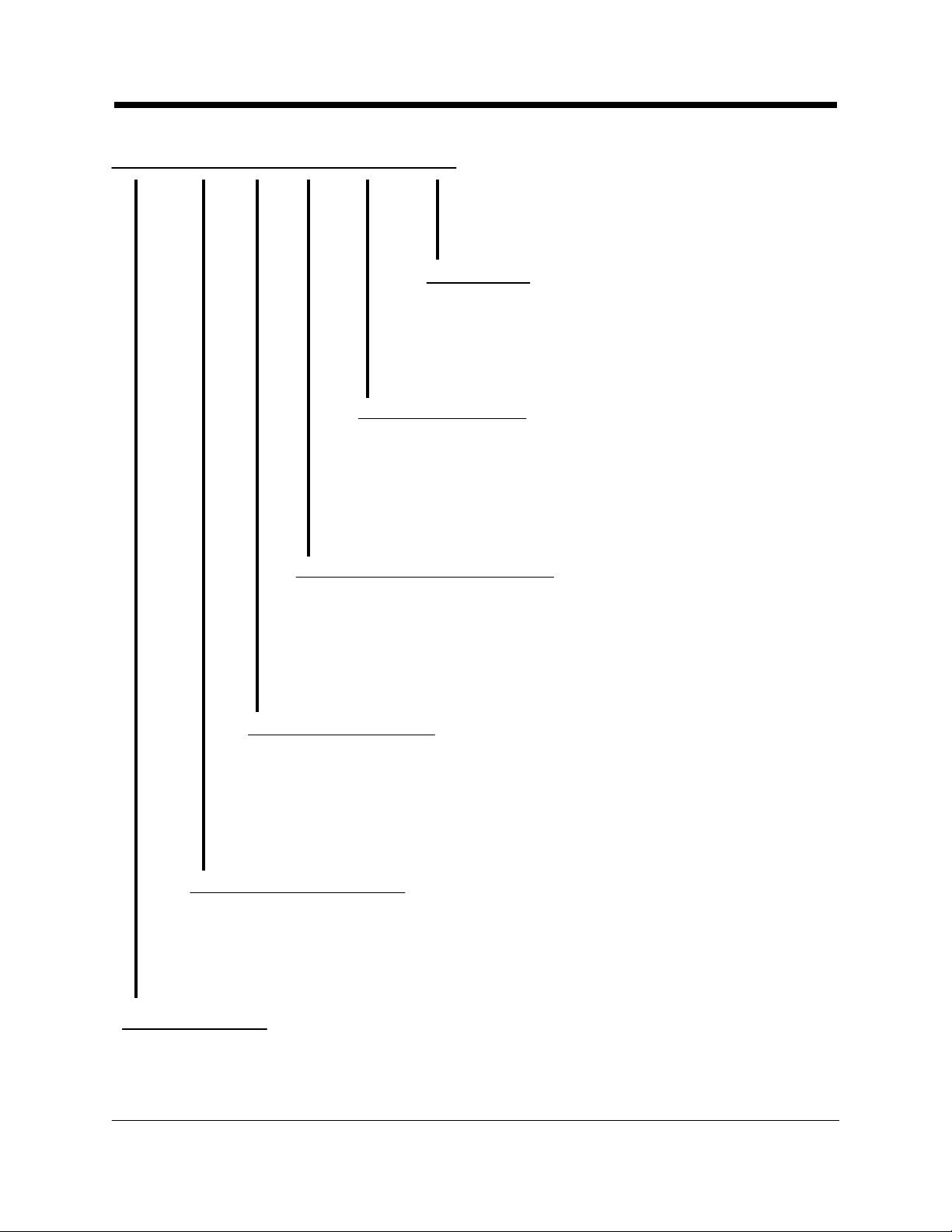
Key to Model Numbers
GB 4 5 1 W HK
C = Full Cube (1-1/4" 1-1/4" x 1-1/4")
HK = Half Cube (1-1/4" x 1/1/4" x 5/8")
K = Cubelet (5/8" x 5/8" x 1-1/4")
A = Air Cooled Condenser-Self Contained
W = Liquid Cooled Condenser-Self Contained
R = For Remote Air Cooled Condenser
1 = 115 Volt-60 Hz.-1 Ph. (2-wire plus Ground)
4 = 208/230 Volt-60 Hz.-1 Ph. (2-wire plus Ground)
5 = 208/230 Volt-60 Hz.-3 Ph. (3-wire plus Ground)
7 = 220/240 Volt-50 Hz.-1 Ph. (2-wire plus Ground)
Electrical Characteristics
Condenser Type
Cube Size
2 = R-502, Copeland Compressor except GB1224/GB1225 (Bristol)
3 = R-502, Bristol Compressor
4 = R-404a, Bristol Inertia Compressor/Polyolester Lubricant except
3 = 300 Series
4 = 400 Series
5 = 500 Series
6 = 600 Series
12 = 1200 Series
Cabinet Width
GB = Horizontal Unit (42" wide)
GT3XX = Slimline Unit (28-1/2" wide)
GT5XX = Slimline Unit (30" wide)
Kold-Draft® Service & Parts Manual Rev:3/
Classic Cuber Series
Modification Code
GT341/GT344 (Bristol Reed Valve Compressor w/POE Lubricant)
5 = R-404a, Tecumseh Compressor w/POE Lubricant
- 2 -
02
Page 4
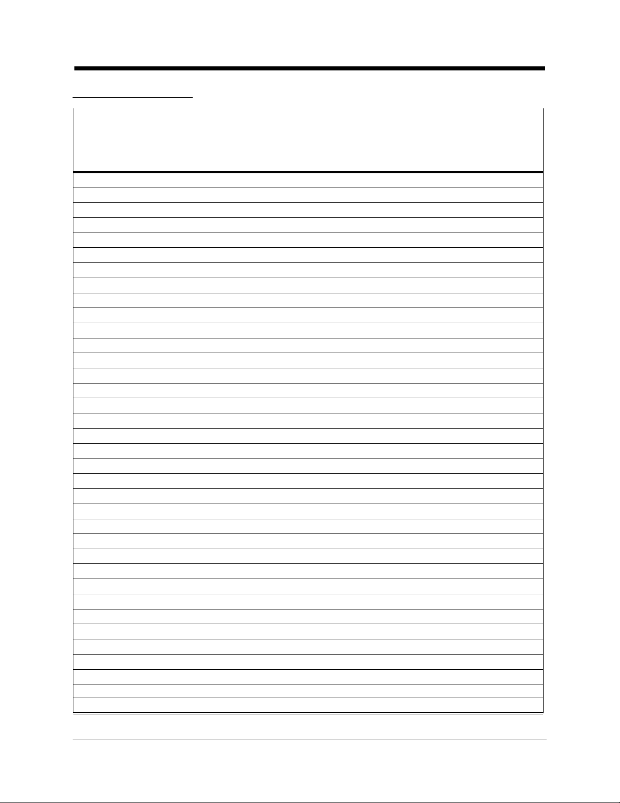
GB Series Cubers
Installation Specifications
FUSE/HACR
BREAKER SIZEMINIMUM
(AMPS)CIRCUITELECTRICAL
NORMAL MAXIMUM
AMPACITYSUPPLYMODEL
25 3021115/60/1GB441A
20 3017.8115/60/1GB441W
20 3017.8115/60/1GB441R
20 2515.3208-230/60/1GB644R
30 5029.1208-230/60/1GB1244W
30 5029.1208-230/60/1GB1244R
20 2515.5208-230/60/3GB1245W
20 2515.5208-230/60/3GB1245R
35 55 32208-230/60/1GB1254W
35 5532208-230/60/1GB1254R
20 2516.9208-230/60/3GB1255W
20 2517.6208-230/60/3GB1255R
25 3523.3115/60/1GB431A
25 3020.1115/60/1GB431W
25 4025115/60/1GB431R
15 2012.7208-230/60/1GB434A
15 159.6208-230/60/1GB434W
15 1511.1208-230/60/1GB444A
15 1510.2208-230/60/1GB444W
20 3019.9115/60/1GB451A
20 2516.4115/60/1GB451W
15 2011.9208-230/60/1GB454A
15 1511.3208-230/60/1GB454W
15 1510.1208-230/60/1GB454R
20 2516.6208-230/60/1GB634A
20 2515.7208-230/60/1GB634W
15 2514.8208-230/60/1GB634R
20 2516.2208-230/60/1GB644A
20 2515.3208-230/60/1GB644W
20 3018208-230/60/1GB654A
20 3017.3208-230/60/1GB654W
20 3017.4208-230/60/1GB654R
30 4528.2208-230/60/1GB1224W
30 4528.2208-230/60/1GB1224R
20 3018.8208-230/60/3GB1225W
35 5534208-230/60/1GB1254A
Rev:3/02 Kold-Draft® Service & Parts Manual
- 3 -
Page 5
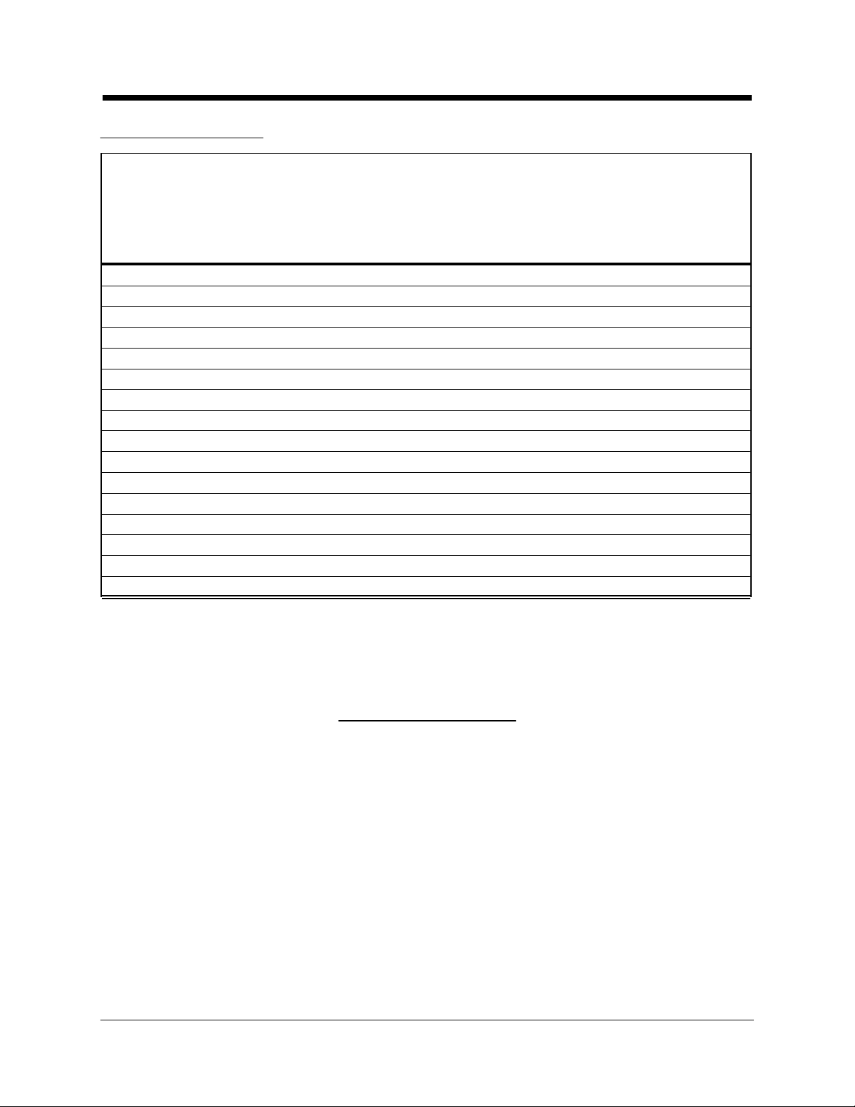
GT Series Cubers
Installation Specifications
FUSE/HACR
BREAKER SIZEMINIMUM
(AMPS)CIRCUITELECTRICAL
AMPACITYSUPPLYMODEL
NORMAL MAXIMUM
20 2517.8115/60/1GT331A
20 2516.6115/60/1GT331W
15 158.6208-230/60/1GT334W
20 2517.8115/60/1GT341A
20 2516.6115/60/1GT341W
15 158.6208-230/60/1GT344A
15 158.6208-230/60/1GT344W
20 2515.6115/60/1GT351A
15 2014.4115/60/1GT351W
15 159.3208-230/60/1GT354A
15 158.6208-230/60/1GT354W
25 35 23.4115/60/1GT551A
20 3017.9115/60/1GT551W
20 3520115/60/1GT551R
15 2514.9208-230/60/1GT554A
15 2014.3208-230/60/1GT554W
Voltage Tolerances
Full-load MINIMUMNo-load MAXIMUMNominal
Kold-Draft® Service & Parts Manual Rev:3/02
- 4 -
104126115
198252208/230
210250220/240
Page 6
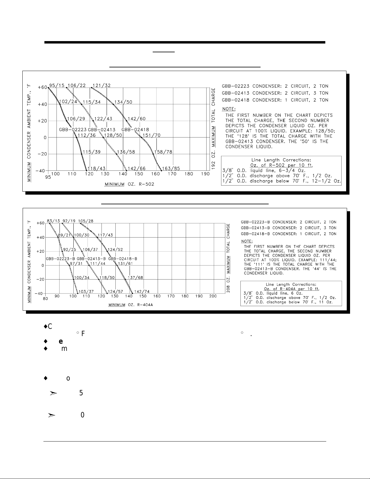
Kold-Draft® Remote Condenser Single Evaporator Cuber Charging Requirements
Installation Guidelines
R-502, Factory charge is 96 oz. (6 lbs.)
R-404a, Factory charge is 84 oz. (5.25 lbs.)
{
Charts based on 30 ft. of 1/2" O.D. discharge (15 ft. exposed to ambient temperature
under 70} F.) and 30 ft. of 3/8" O.D. liquid return lines, at 20} F., T.D.
{
Lines over 50 ft. are not recommended.
{
Minimum Condenser Height: Condenser must be install ed above refrigerant line quick
connects at rear of ice machine. No part of the refrigerant lines, between the cuber
and the condenser, should fall below this point.
SEE SEPARATE INSTRUCTIONS FOR THE CONDENSER.
{
For Condensers other than Kold-Draft®, the install er must determine the condenser
liquid volume at minimum operating temperature.
ˆFor R-502 Cubers, the basic charge is 2 lbs. To this, add the condenser liquid
volume calculation and the line charge calculation from the Line Length Correction
Chart to obtain the minimum total charge.
ˆFor R-404a Cubers, the basic charge is 1-3/4 lbs. To this add the condenser liqui d
volume calculation and the line charge calculation from the Line Length Correction
Chart to obtain the minimum total charge.
Rev:3/02 Kold-Draft® Service & Parts Manual
- 5 -
Page 7

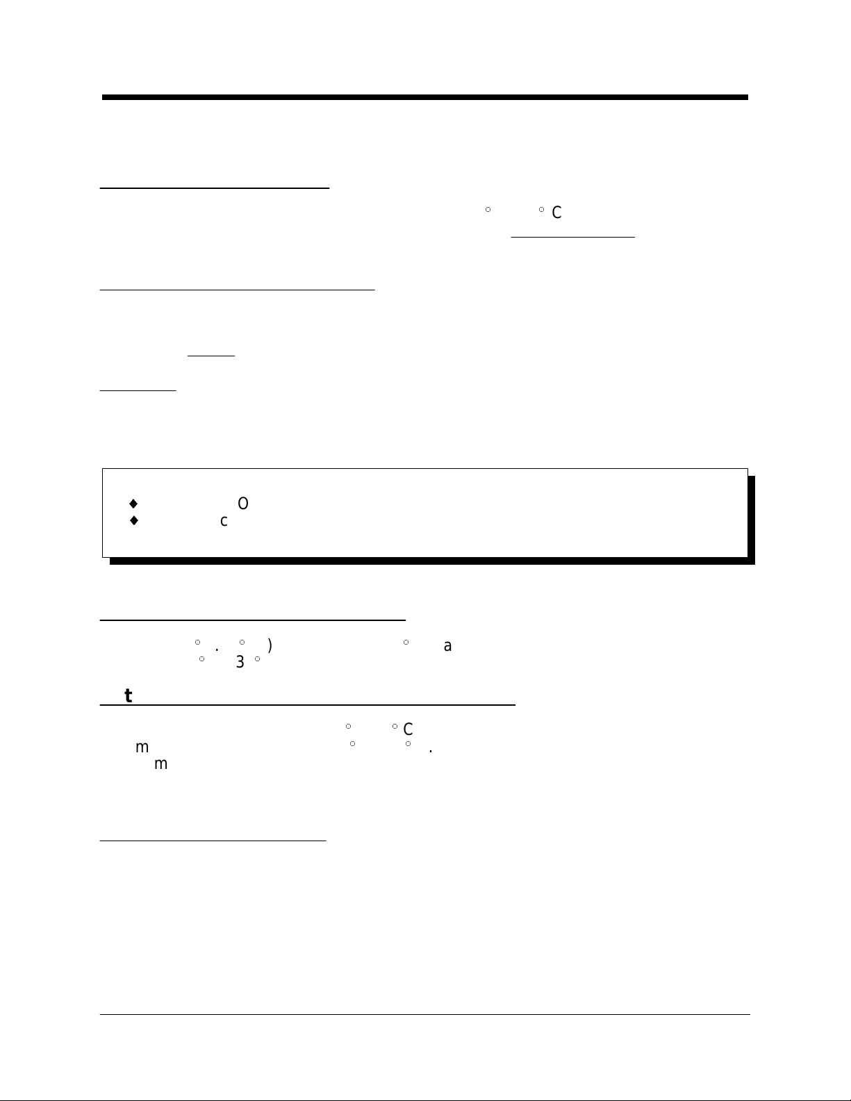
Kold-Draft® Remote Condenser Dual Evaporator Cuber Charging Requirements
Installation Guidelines
R-502, Factory charge is 128 oz. (8 lbs.)
R-404a, Factory charge is 112 oz. (7 lbs.)
{
Charts based on 30 ft. of 1/2" O.D. discharge (15 ft. exposed to ambient temperature
under 70} F.) and 30 ft. of 3/8" O.D. liquid return lines, at 20} F., T.D.
{
Lines over 50 ft. are not recommended.
{
Minimum Condenser Height: Condenser must be installed above refrigerant line quick
connects at rear of ice machine. No part of the refrigerant lines, between the cuber
and the condenser, should fall below this point.
SEE SEPARATE INSTRUCTIONS FOR THE CONDENSER.
{
For Condensers other than Kold-Draft®, the install er must determine the condenser
liquid volume at minimum operating temperature.
ˆFor R-502 Cubers, the basic charge is 3-1/2 l bs. To this, add the condenser l iquid
volume calculation and the line charge calculation from the Line Length Correction
Chart for the total charge.
ˆFor R-404a Cubers, the basic charge is 3 lbs. To this, add the condenser liquid
volume calculation and the line charge calculation from the Line Length Correction
Chart to obtain the minimum total charge.
Kold-Draft® Service & Parts Manual Rev:3/02
- 6 -
Page 8

GB Cubers
energy efficiency can be obtained by reducing water fill level (lowering the high-level
Installation Guidelines
GB4XX GB6XX GB12XX
PARAMETER
Water fill level
*Approximate cycle time, min. 15 33/26 13 25.5/21 12 22.5/18
Approximate harvest weight, lb. 4.0 7.7/7.1 4.0 7.7/7.1 8.0 15.4/14.2
---------------------------------------------------------------------------------------------------------------------------------------
REFRIGERANT CHARGE,
-------------------------------------------------------------------------------------------------------------------------------------- GB44X GB 4 5X GB64X GB124X
REFRIGERANT CHARGE,
Oz. (R-404a) Air cooled: 22 19 28 62
(Top of tank to level in control tube)
GB43X GB63X GB122X
Oz. (R-502) Air cooled: 25 Air cooled: 35 ------
Liq. cooled: 22 Liq. cooled: 22
Liq. cooled: 20 20 22 52
Remote(MAX): 208 208 208 272
Remote(MAX):192 Remote(MAX):192 Remote(MAX):256
K C/HK K C/HK K C/HK
3-5/8" 2-3/4" 3-5/8" 2-3/4" 3-5/8" 2-3/4"
MODEL SERIES/CUBE SIZE
MODEL SERIES
MODEL SERIES
GB65X GB125X
Liq. cooled: 60
GT Cubers
MODEL SERIES/CUBE SIZE
GT3XX GT55X
K C/HK K C/HK
PARAMETER
Water fill level
*Approximate cycle time, min. 14 31/21 15.5 31/24
Approximate harvest weight, lb. 2.0 3.9/3.5 4.0 7.7/7.1
--------------------------------------------------------------------------------------------------------------------------------------
REFRIGERANT CHARGE, Oz. (R-502
--------------------------------------------------------------------------------------------------------------------------------------
GT34X GT35X GT55X
REFRIGERANT CHARGE,
Oz. (R-404a) Air cooled: 24 Air cooled: 19 Air cooled: 30
(Top of tank to level in control tube)
3" 2-5/8" 3-5/8" 2-3/4"
MODEL/SERIES
GT33X
)
Liq. cooled: 22
MODEL SERIES
Liq. cooled: 20 Liq. cooled: 20
------ ------
Air cooled: 27
Liq. cooled: 20
Remote(MAX):208
* Values are for Air-cooled (or GB12XXW) models at 90} F. air/70} F. water
temperatures with cuber adjusted to produce fully-formed ice. Greater capacity and
Rev:3/02 Kold-Draft® Service & Parts Manual
- 7 -
Page 9
probe) to produce ice with larger dimples. A slight adjustment of the probe will result in
Installation Guidelines
a noticeable effect on dimple size. The control stream will not rise over the dam with
lower water fill levels than indicated above.
All Liquid Cooled Models
The recommended condensing temperature is 104} F.(40} C.). If necessary to adjust
the coolant regulator valve, the high si de pressure at mid-freeze cycle should be 230
psig for R-502 or 250 psig for R-404a.
All Remote Air Cooled Models
Fan cycling controls are not provided and are not beneficial except to automatically
stop the fan during off-cycles. If such controls are used the settings should not allow
fan cycling during freeze cycles. The suggested settings for fan cycli ng controls are:
ON at approx. 250 psig; OFF at approx. 220 psig
CAUTION: Fan cycling controls do not reduce the minimum charge requirements. If
there is not an adequate amount of liquid refrigerant in the receiver at start-up, the
system will pump down repeatedly or run at a very high superheat (l ow back-pressure)
with little -or- no refrigeration at the evaporator(s). Refer to the Remote Condenser
Model Charging Requirements section.
CAUTION:
{ RISK OF PROPERTY DAMAGE, EQUIPMENT FAILURE, OR FIRE.
{ Failu re to comply with all installation specifications and instructions may cause
erratic operation and the risk of damage or fire.
Ambient Operating Temperatures
Minimum: 45
Maximum: 90} F. (32
}
F. (7} C.) NOTE: Under 60} F may cause erratic bin thermostat operation
}
C.)
Potable Water and Condensing Liquid Supply
Minimum Water Temperature: 45} F. (7} C.)
Maximum Water Temperature: 90} F. (32} C.)
Minimum Water Pressure: 30 psig
Maximum Water Pressure: 100 psig*
* If regulator is used, recommended setting is 30 to 50 psig
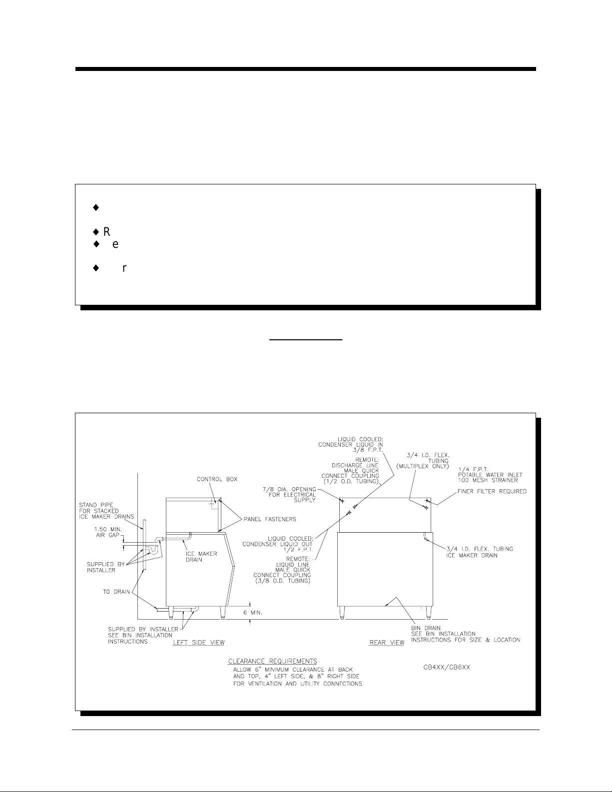
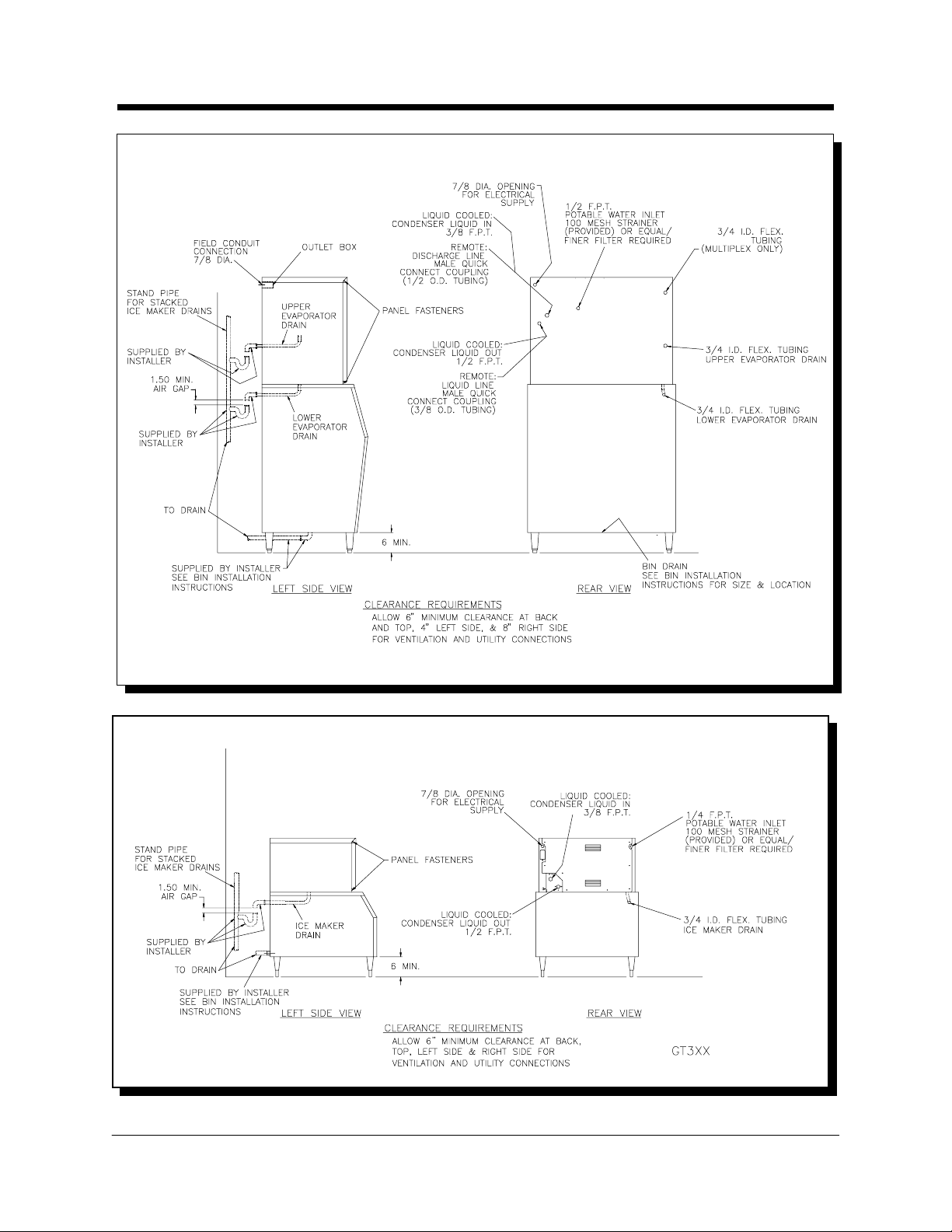
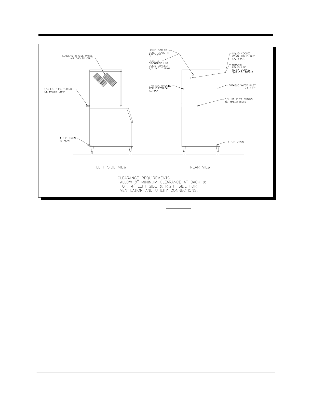
Clearance Requirements
GB Cubers (except GB1250A---see the following drawings)
REAR (beyond condenser if protruding from cabinet) and TOP: 6 inches
RIGHT SIDE: 8 inches
LEFT SIDE: 4 inches
GT 3XX Cubers GT55X Cubers
REAR and TOP: 6 inches 8 inches
RIGHT SIDE: 6 inches 4 inches
LEFT SIDE: 6 inches 4 inches
Kold-Draft® Service & Parts Manual Rev:3/02
- 8 -
Page 10
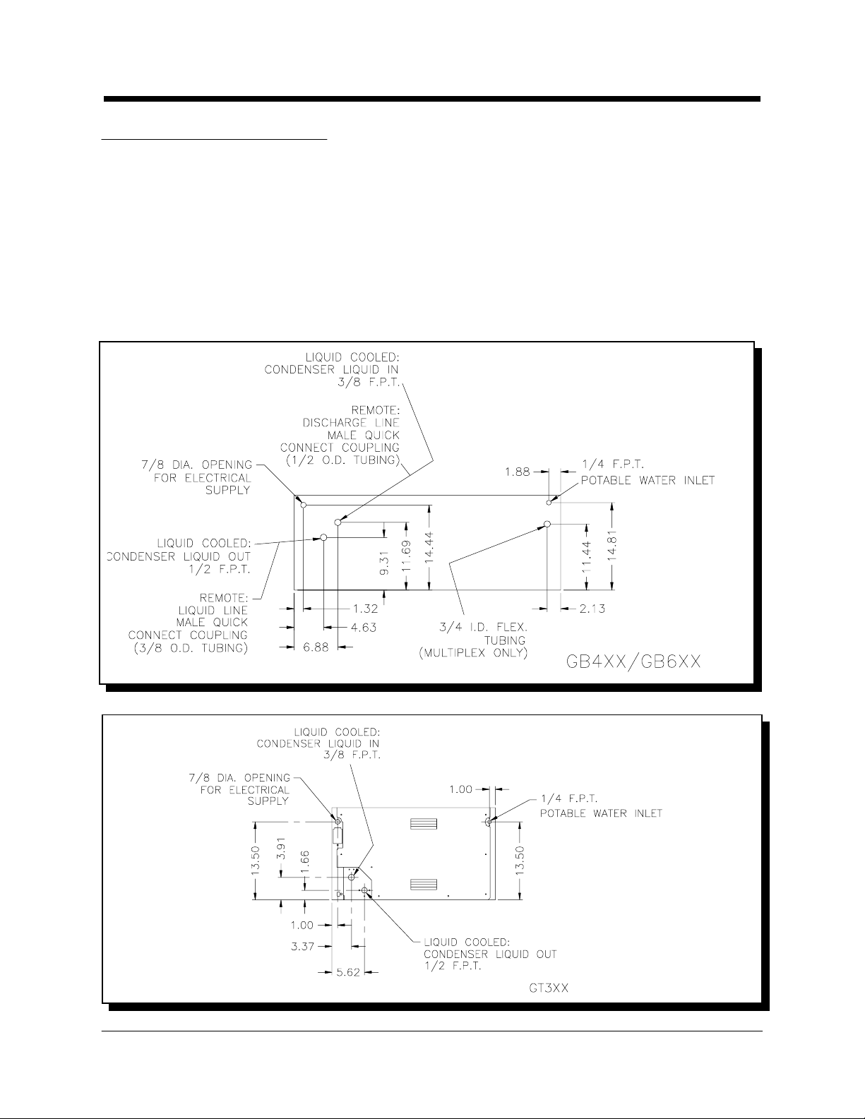
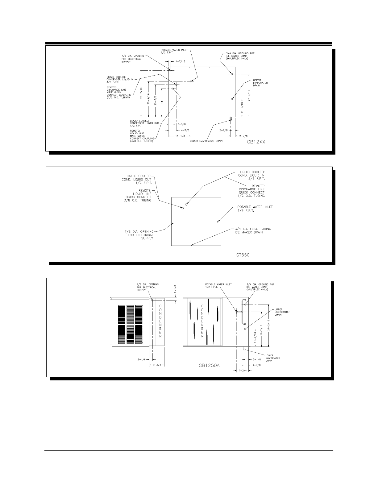
Plumbing Requirements
Installation Guidelines
Potable Water Inlet Fitting: 1/4" F.P.T. (GB430/GB440/GB450/GB630/GB640/GB650)
1/2" F.P.T. (GB1220/GB1240/GB1250)
1/4" F.P.T. (GT330/GT340/GT350/GT550)
Drain: 3/4" I.D. flexible tubing
Liquid Cooled Condenser Inlet Fitting: 3/8" F.P.T.
Liquid Cooled Condenser Outlet Fitting: 1/2" F.P.T.
Remote Air Cooled Liquid Line Fitting: 3/8" Tubing Quick Connect
Remote Air Cooled Discharge Line Fitting: 1/2" Tubing Quick Connect
Electrical, water and drain locations are shown on the following (5) drawings:
Rev:3/02 Kold-Draft® Service & Parts Manual
- 9 -
Page 11
Water Treatment
Please consult your local water conditioning supplier for specific recommendations.
Installation Guidelines
There are no specific requirements for water treatment provided that the ice making
supply water is potable and not laden with sediment. The use of additional water
treatment may facilitate or reduce the frequency of the need for cleaning as well
as reduce the corrosive effects of chlorinated (greater than 0.2 ppm residual
chlorine) water supplies.
Kold-Draft® Service & Parts Manual Rev:3/02
- 10 -
Page 12
General Information
CAUTION:
{ RISK OF PROPERTY DAMAGE, EQUIPMENT FAILURE OR FIRE.
{ Failure to comply with all installation specifications and instructions may cause
erratic operation and the risk of damage or fire.
Ampacity: Minimum ampacity does not indicate typical running current value. Refer to
equipment NAME PLATE data. Use minimum ampacity value for sizing branch circuit
conductors up to 25 feet in length. For conductor length over 25 feet up to 100 feet,
increase 1 AWG size. Over 100 feet requires a 2 or more AWG size increase.
Branch circuit protection: Proper protection must be provided by either fuse(s) or
HACR type circuit breaker(s). Each ice maker must be provided with a separately
protected circuit with no other load(s). A fused disconnect installed adjacent to each ice
maker is recommended (must be supplied by installer), and may be required by local
codes. NORMAL protector size is based on rated voltage and operati on at lower than
extreme temperature limits. When branch circuit conductors are sized to permit,
increasing the protector size (up to the specified maximum) may avoid nuisance
protector opening under harsh operating conditions.
Water supply: Minimum 30 psig supply pressure while the ice maker is filling is
required. The water fill rate is 0.6 GPM for each GT330, GT340, or GT350, 1 GPM for
each GB430, GB440, GB450, GB630, GB640, GB650, or GT550, and 2 GPM for each
GB1220, GB1240, or GB1250. Backflow/Backsiphonage protection is provided by an
internal ai r gap (accepted by NSF). If additional protection is required by local codes or
authorities, any device(s) and installati on of the same, including specification and cost,
are the responsibility of the installation specifier.
Ice maker drain: The size of the gravity drain for the ice maker purge and rinse water
must not be reduced. Individual drains from stacked ice makers may be discharged into
a standpipe or manifold with a minimum 1-1/2 inch air gap at each ice maker
connection.
Liquid condenser coolant pressure drop: Condenser coolant pressure drop may
reach 20 psig during peak load with 85} F. coolant temperature at recommended
refrigerant high-side pressure. The condenser coolant (water) regulating valve may
require adjustment due to variations in the coolant supply characteristics to provide
optimum efficiency.
Remote condenser models: Remote condenser models from the factory carry a
minimal charge and will likely require an additional refrigerant charge to accommodate
all condenser ambient temperatures and/or the volume potentially contained in
refrigerant lines and condensers. There is a label on the receiver that i ndicates factory
charge and the maximum charge, along with a space to write in the total system
charge. Ice makers are provided with re-sealable refrigerant l ine connection coupl ings.
For all remote condenser installations refer to the Installation Guidelines located in
the front of this manual.
All models are intended FOR INDOOR USE ONLY with PERMANENT CONNECTION
TO THE FIELD ELECTRICAL SUPPLY. The remotely-installed condensers supplied by
Kold-Draft® may be installed outdoors, and they require a separate electrical supply.
Rev:3/02 Kold-Draft® Service & Parts Manual
- 11 -
Page 13
Cleaning: Usually at 3 to 6 months intervals, depending on water conditions.
Preventative Maintenance
Inspections: During cleaning - at least twice a year.
Service: All such equipment will require service at some time. Service requirements
will be minimized with faithful preventative maintenance including good housekeepi ng
at the i nstal lati on si te. A CALL F OR SERVICE AS SOON AS A POSSIBL E PROBLEM
IS NOTICED MAY AVOID EXTENSIVE REPAIRS.
CAUTION:
{ RISK OF PERSONAL INJURY OR PROPERTY DAMAGE.
{ Do not use ammonia solutions in cleaning any part of the ice maker.
{ Do not mix ice machine cleaner and sanitizer together.
{ Use rubber gloves, eye protection and an apron.
{ Clean up splashes or spillage immediately.
{ Follow these instructions exactly.
Ice Cuber Cleaning Instructions
1. GB & GT55X: Mix one bag of Kold-Draft® ice machine cleaner (55R-01000) in
(2) quarts, or GT3XX: Mix 1/2 bag of Kold-Draft® ice machine cleaner
(55R-01000) in (1) quart of clean, warm water (180
evaporator/water plate assembly to be cleaned.
2. If the cuber is operating, wait until a harvest cycle occurs then trip the
'ICE-OFF-WASH' switch to 'WASH' as soon as the water plate begins to close.
3. Empty all ice from the storage bin and shut off other ice makers on the same
bin.
4. After the water fill is completed, switch the 'ICE-OFF-WASH' to 'OFF'. While
pinching the water level control hose, carefully remove the water level control
tube from the cap. HOLD THE TUBE HIGH ENOUGH SO THAT THE TUBE
DOES NOT OVERFLOW. Release the hose and pour about half of the mixed
cleaner into the tube. Replace the tube on the cap, while pinching the water
level control hose, then pour the remaining cleaner into the control stream box.
5. Switch the 'ICE-OFF-WASH' to 'WASH' and allow the cleaner to circulate for
approximately 15 minutes, then pull the right side of the water plate down until
the pump stops and hold it until the pump will not re-start when released.
6. The water plate will open and dump the cleaner then close immediately, and the
water system will refill. Repeat this dumping and refilling three (3) times to rinse
out all of the cleaning solution.
7. Mix a sanitizing solution of two (2) oz. 5-1/4% sodium hypochlorite (household
bleach or equivalent) and one (1) quart clean water.
8. As in step #4, pour about half of the sanitizing solution into the water level
control tube and the remaining sanitizer into the control stream box.
9. Allow the sanitizing solution to circulate AT LEAST 15 MINUTES, then dump
and rinse two (2) times as described above. If necessary, reset the water level
probes to the proper levels.
}
F. MAX.) for each
Kold-Draft® Service & Parts Manual Rev:3/02
- 12 -
Page 14
10. While the cleaning and sanitizing solutions are circulating, clean, rinse and
Preventative Maintenance
sanitize all accessible parts of the ice-making compartment of the cuber with
clean cloths. Use a cleaning solution of 8 tablespoons (1/2 cup) baking soda
per gallon of warm water, and a sanitizing solution of no less than 1 teaspoonful
(5 ml.) 5-1/4% sodium hypochlorite per quart of clean water.
11. After cleaning has been completed, trip the 'ICE-OFF-WASH' switch to 'ICE'
and check to be sure that the cuber is operating properly, particularly the water
level probes. Then re-assemble and secure all cabinet enclosure panels.
Ice Bin Cleaning Instructions
The bin should be cleaned periodical ly. If bin drain has any horizontal run, remove ice
from left side of bin and flush with two (2) quarts of hot water monthly. (Long drain lines
should be flushed weekly.)
1. Clean exterior of bin frequently.
2. To clean the interior, follow the instructions provided with bin.
3. Empty the storage area and disconnect the electrical power supply to the ice
maker(s).
4. Remove the ice maker inspection panel, top, left and right end panels, and
drain pan. Sliding bin doors may be removed by lifting them up, then pulling out
from the bottom.
5. When cleaning the ice maker, follow the ice maker cleaning instructions and
clean the bin last.
6. Replace all enclosure panel s and drain pan before re-connecting the electrical
supply.
CAUTION:
{ RISK OF PERSONAL I NJ URY, EQ UI PMENT DAMAGE O R CONTAMINATION
OF THE ICE BIN.
{ Do not use ammonia solutions or strong detergents in cleaning any part of the
ice maker or bin.
{ Never use appliance polishes, finish preservatives or cleaners in ice storage
areas.
Winter Conditioning
Ice cubers that are idle in the winter months require preparation to prevent damage
from freezing. The following procedure should insure the safety of the cuber so that it
can be started easily the following year.
1. Shut off and detach the water supply to the ice cuber.
2. If the cuber contains a water-cooled condenser, the cuber must be running
while air is introduced through the condenser water inlet connection to blow the
water out of the condenser coils.
3. The cuber shoul d then be run into defrost to drain the water tank and air should
be introduced into the water inlet to blow out the water solenoid.
Rev:3/02 Kold-Draft® Service & Parts Manual
- 13 -
Page 15
CHECK FOR FREIGHT DAMAGE BEFORE PROCEEDING. Even though damage to
GB &
GT
Cuber
Installation Instructions
the carton may not have been evident, check for hidden damage and contact freight
carrier immediately, if necessary, to file a claim.
THIS EQUIPMENT MUST BE INSTALLED IN COMPLIANCE WITH THE
APPLICABLE FEDERAL, STATE/PROVINCE AND/OR LOCAL PLUMBING,
ELECTRICAL AND HEALTH/SANITATION CODES AND REQUIREMENTS.
CAUTION:
{ RISK OF PERSONAL INJURY, PROPERTY DAMAGE, EQUIPMENT FAILURE
OR FIRE.
{ Refer all maintenance to qualified personnel.
{ Never operate this equipment with covers, panels or other parts removed or not
properly secured.
{ Warn all users to clean up spillage immediately, keep storage bin doors closed,
and report any apparent leakage or unusual sounds to responsible maintenance
personnel.
Installation
NOTE: For Multiplex Installations, please refer to Multiplex specific instructions before
proceeding.
Clearance and Utility provisions are shown on the following (4) drawings:
Kold-Draft® Service & Parts Manual Rev:3/02
- 14 -
Page 16
GB &
GT
Cuber
Installation Instructions
GB1220
GB1240
GB1250
Kold-Draft® Service & Parts Manual Rev:3/02
- 15 -
Page 17
GB &
GT
Cuber
Installation Instructions
GT55X
1. Position the ice storage bin so that minimum clearances will be available
around the ice maker for ventilation and utility connections.
2. Level the bin with adjusters on legs, or by shimming if the bin is to be sealed to
the floor. If gaps due to shi ms are greater than 1/8 inch, instal l a cove molding
around the bin bottom. Seal the bin or molding to the floor with NSF Certified
RTV sealant (Dow Corning RTV 732 or equal).
3. Remove the cuber cabinet TOP Panel as follows: Lift from the front and pull
forward (GT55X push backward) until the rear clip is disengaged from the
chassis..
4. Remove the remaining cuber cabinet panels as follows:
FRONT: Remove the (4) screws at the bottom and front-sides, pull forward.
SIDES: Pull forward and lift to disengage the clips from the chassis.
NOTE: When re-installing the panels, make sure that the screws engage the
TOP panel.
5. GB: Remove the ice deflector(s), ice chute(s) and drain pan(s). The Drain tube
assembly(s) is(are) packed with the drain pan(s).
GT3XX: Remove the ice chute/drain pan. The drain tube is packed with the
drain pan.
GT55X: Remove the ice chute and drain pan. The drain tube is packed with the
drain pan.
Kold-Draft® Service & Parts Manual Rev:3/02
- 16 -
Page 18

6. Install gasketing on top of bin if required. Gasket material must be positioned so
GB &
GT
Cuber
Installation Instructions
that it extends to the outside edge of the perimeter of the cuber chassis when
the cuber is in place.
7. CAREFULLY place the cuber onto the gasketed bin, noting the alignment of the
mounting holes in the chassis if mounting means are provided on the bin.
Follow the bin installation instructions for securing the cuber to the bin.
8. GB: Install the drain pan(s), ice chute(s) and ice deflector(s). Route the drain
tube assembly(s) through the rear of the bin, and clamp the tubing to the
drain pan nipple(s).
GT3XX: Install the drain pan/chute. Route the drain tube through the rear of the
bin, and clamp the tubing to the drain pan nipple.
GT55X: Install the drain pan. Route the drain tube through the rear of the
cuber, and clamp the tubing to the drain pan nipple.
WARNING:
{ RISK OF CONTAMINATION OF ICE IN THE BIN.
{ Provide separate, unconnected drains for the ice maker and the bin.
{ Consult local codes for sui table connections to the building drains.
9. Purge the potable water supply line.
10. Remove the water plate shipping strap(s).
11. GB: Route the bin thermostat capillary tube through the grommet, in the
condensing unit pan and push all the way down. (See the following diagrams)
Note- It may be necessary to increase the distance that the cap tube enters the
ice storage area. Bin geometry, deflectors, baffles, etc., may cause an ice jamb
above the bin door opening. Carefully uncoil the insulated loop of cap tube,
while recoiling it further up, to lower the bin fill level. Cautio
cap tube. THIS SECTION IS AS REVISED SEPTEMBER, 2004.
n: do not kink the
Kold-Draft® Serv ice & Parts Manual Rev:3/02
- 17 -
Page 19
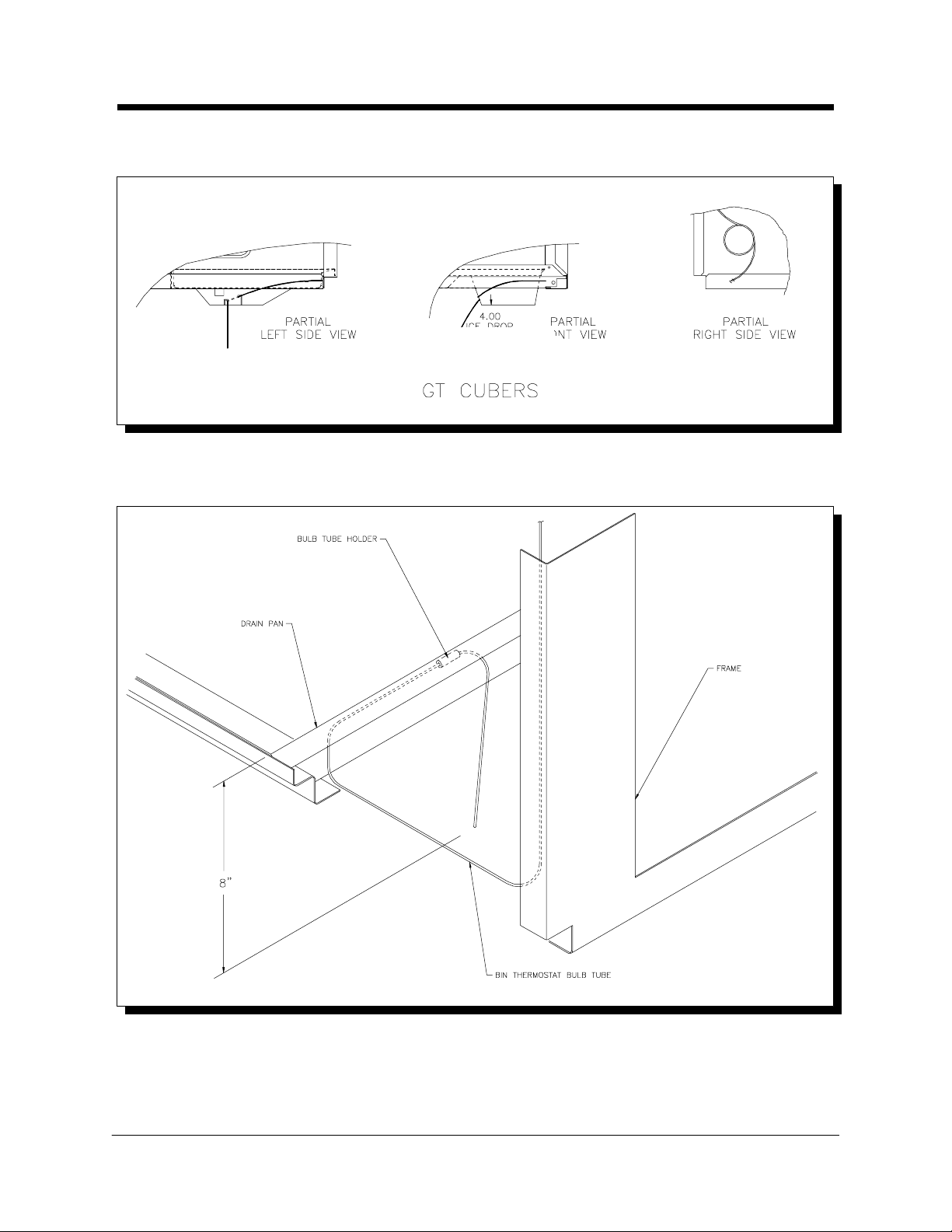
GT3XX: Route the bin thermostat capillary tube through the grommet in the
GB &
GT
Cuber
Installation Instructions
right end frame wall and under the ice chute. See the diagram and notes
following for location and securing of the capillary tube.
GT3XX CUBER S
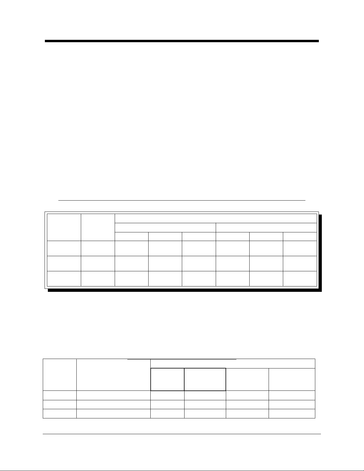
GT55X: Route the bin thermostat capillary tube along the right end frame
wall and front rail, out through the bulb hol der and down into the bi n. See the
diagram following for location and securing of the capillary tube.
12. If start-up will not occur immediately, secure all cuber cabinet panels now.
INSTALLER NOTE: There is no electrical interconnection provisi on in "R" models for
the condenser fan.
Kold-Draft® Serv ice & Parts Manual Rev:3/02
GT55X CUBERS
- 18 -
Page 20

Consult the Installation Specifications, Sequence of Operation and Service and
Cuber
Start-up
Instructions
Troubleshooting sections if variations from the following description of operation are
noticed.
1. Remove the top and front cabinet panels.
2. Be sure that the 'ICE-OFF-WASH' switch is in the center 'OFF' position.
3. Install and connect refrigerant lines and condenser on "R" models.
4. Turn on supply water and power. Be sure that condenser liquid ("W" models) or
refrigerant lines and condenser ("R" models) are ready for use before turning
power on. Check for leaks in water/liquid supply connections. NOTE, "R"
MODELS ONLY: The compressor will start immediately when power is applied,
regardless of the 'ICE-OFF-WASH' switch position, if the low-side pressure
is at or above the pump-down controller cut-in setting. Be sure that the
compressor stops when the low-side pressure is between 5 and 10 psig.
5. Be sure that pump hoses are connected, then pour approximately one pint of
clean tap water into the circulation system to lubricate the pump seal.
6. Move the 'ICE-OFF-WASH' switch to the right 'WASH' position and observe the
water fill cycle and the pump running. If all water distributor holes do not
produce full streams and the appearance of air i s evident i n the tube, pi nch the
plastic tube connected to the water solenoid valve outlet while water is running
until the streams are full all the way across the distributor tube. Water fill is
complete when the water in the liquid level control tube reaches the high-level
probe. At this time, observe that the water shuts off and that there are no water
leaks (dripping into the drain pan). NOTE: In dual-evaporator models, be
sure that the Master and Slave water fill level difference is less than 1/4"
for "K" or 1/8" for "C" or HK" cube sizes. See LIQUID LEVEL
CONTROLLER text.
Kold-Draft® Service & Parts Manual Rev:3/02
7. Pull the right end of the water plate down, stretching the springs until the pump
stops, and hold until the pump does not re-start when released. The water plate
will open fully to dump the batch of water previously taken in, then close
immediately. The water plate should stop when it is fully closed, and the water
fill cycle will repeat.
8. After the water fill is complete, move the 'ICE-OFF-WASH' switch to the left
'ICE' position and observe that the compressor (and fan in "A" models) starts,
and the water pump continues to run. The refrigeration system operation should
be checked during the first few cycles, and any adjustments should be made at
this time. Consult the "Controls and Adjustments" section in this manual.
Initial ice making cycles may exhibit super-cooling of the circulating water so
that ice crystals form in the circulating water (slush), possibly stopping the flow
momentarily. If water goes over the control stream dam when circulation
resumes after two (2) cycles AND with all skin panels installed, consult the
Factory.
- 19 -
Page 21
9. Test the bin thermostat(s) by holding some ice against the capillary tube(s). If
Cuber
Start-up
Instructions
necessary, adjust the thermostat(s) so that the ice maker(s) shut off within 30
seconds after ice contacts the capillary tube(s).
10. Be sure that the (GB: drain pan(s), ice chute(s) and deflector(s) are in place,)
(GT: drain pan and ice chute is in place,)
and that the electrical control box cover(s) is(are) secured, then replace the
cabinet panels(skins). Start with the SIDE panels, then the FRONT panel.
Secure the FRONT panel with (2) screws along the bottom edge, replace the
TOP panel and finally secure all the panels with (2) screws in the TOP-SIDES
of the machine.
11. Discard ice from start-up cycles, then clean and sanitize the bin following the
instructions provided with the bin.
12. Complete and mail the Registration Certificate and leave all instructions with the
owner/user. Emphasize the "CAUTION: RISK OF PERSONAL INJURY..."
notice on the first page of the GB & GT Cuber Installation Instructions, and
the importance of Preventative Maintenance.
CHART OF TYPICAL REFRIGERANT OPERATING PRESSURES
All pressures are in psig
TIME
R-502 or
R-404a
freeze cycle
harvest
Approx. 150Approx. 15070 to 150Harvest
cycle
HIGH-SIDELOW-SIDE,
Minimum
R-404aR-502
RAWRAW
200 Min. ******250*180 Min. ******230*Approx. 50Beginning of
200 Min. *******250*180 Min. *******230*12 to 20Just before
Approx. 150Approx. 150150
150
Minimum
All pressures may vary with operating conditions and adjusrments.
* 104o F condensing temperature--adjustable with coolant regulator valve.
** High-side pressure at beginning of freeze cycle in "A" models is likely to be
higher than pressures shown for "W" models.
*** High-side pressure just before harvest in "A" models in cool ambients is likely to
be lower than pressures shown for "W" models.
**** See remote condenser charging requirements if lower than minimum shown.
ICE CUBE SIZES AND WEIGHTS
Weights and Cubes per Batch
CUBE SIZE
LETTER
DIMENSIONS
(Inches/cm)
Weight,
each cube
(oz./g)
GT3XX
GB4XX,
GB6XX
GT5XX
GB12XX
216108541.15/32.61.2 x 1.2 x 1.2/3.1 x 3.1 x 3.1C
4322161080.53/151.2 x 1.2 x 0.6/3.1 x 3.1 x 1.5HK
4322161080.3/8.50.6 x 0.6 x 1.2/1.5 x 1.5 x 3.1K
Kold-Draft® Service & Parts Manual Rev:3/02
- 20 -
Page 22
Section I
GB Multiplexing Instructions
Stacking new GB Classic units above new GB Classic units
and old GB Classic units above new GB Classic units
CAUTION:
{ RISK OF PERSONAL INJURY, PROPERTY DAMAGE, EQUIPMENT FAILURE
OR FIRE.
{ Refer all maintenance to qualified personnel.
{ Never operate this equipment with covers, panels or other parts removed or not
properly secured.
{ Use a suitable lifting means and be careful of sharp edges.
NOTE: Please refer to Section II of these instructions for installing a new GB Classic
unit above an old GB Classic unit.
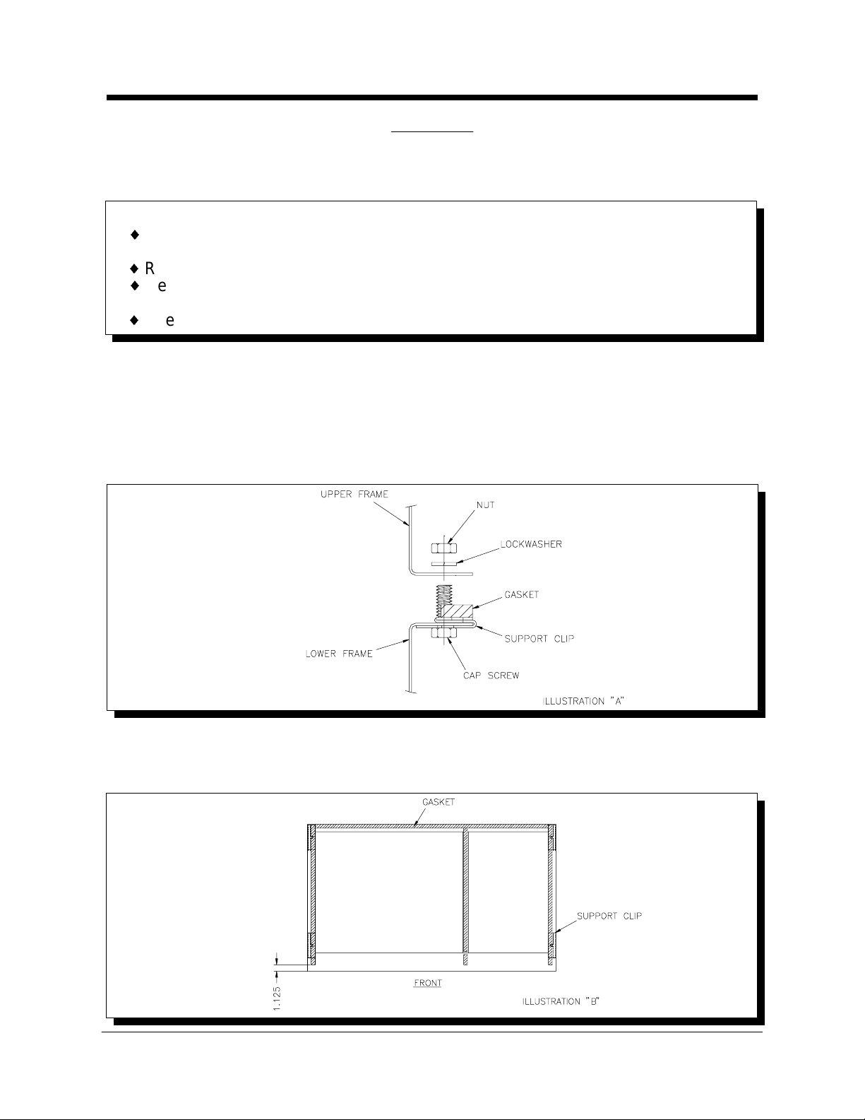
1. Remove cabinet panels from upper and lower ice makers.
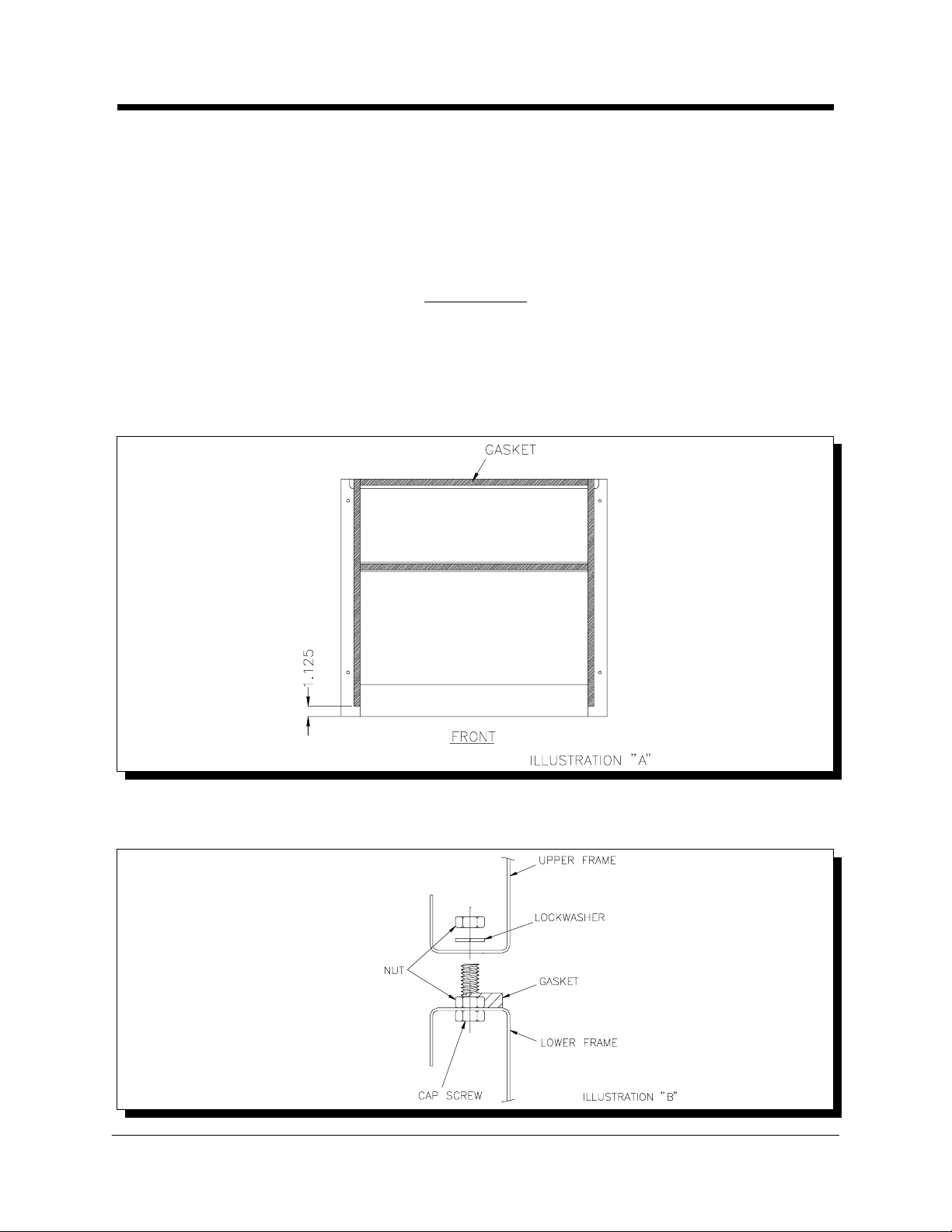
2. Mount support clips on top side flanges of lower ice maker frame and position
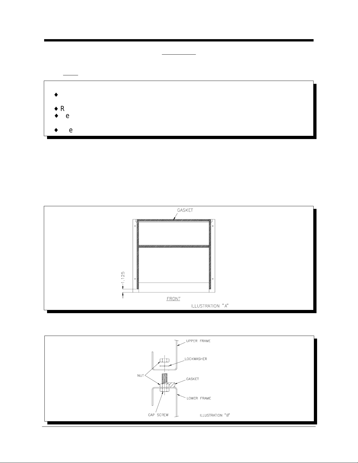
so the clip hol es are aligned with the holes in the frame. (See Illustration "A")
The lower flange of the front support clips must slide into the space between the
top side flange of the ice maker and the top flange of the electrical box.
3. Apply gasket (supplied with kit) to the lower ice maker frame and cut to fit. (See
Illustration "B") Place gasket over the supports clips already in position and
pierce the gasket where it covers the mounting holes.
Kold-Draft® Service & Parts Manual Rev:3/02
- 21 -
Page 23
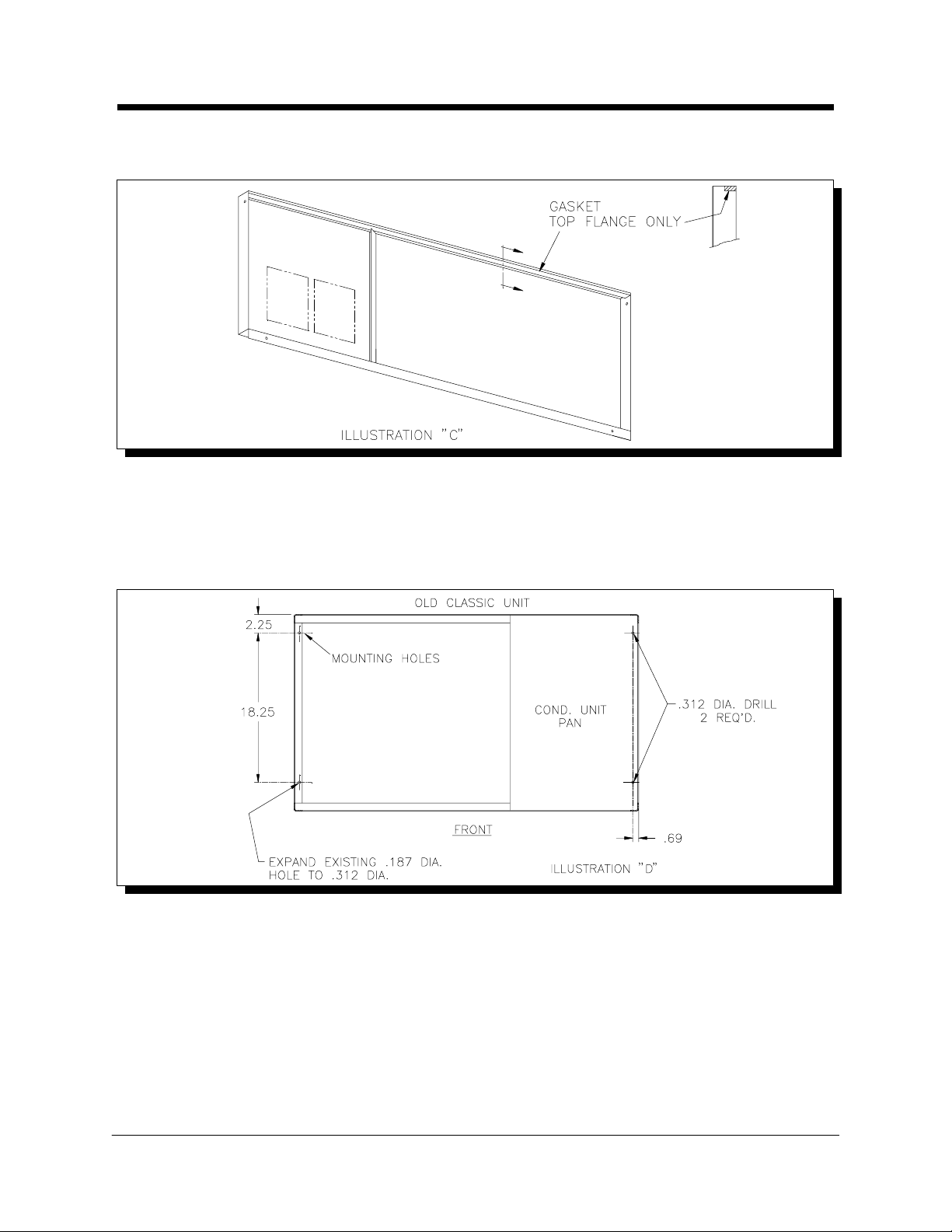
4. Apply gasket to the top inside flange of the lower ice maker front cabinet panel.
GB Multiplexing Instructions
(See Illustration "C")
5. On installations with old GB Classic units it is necessary to drill (2) 5/16" dia.
holes and enlarge (1) 3/16" dia. hole to 5/16" dia. in the bottom of the old
Classic frame. (See Illustration "D") The transformer box will have to be moved
temporarily in order to do this. The two right side holes can be drilled through
the cond. unit pan from the underside, using the existing frame holes as a
guide.
6. Position upper ice maker on lower unit and align mounting holes. Install cap
screws, lock washers and nuts. (See Illustration "A") CAUTION: Support upper
unit until all fasteners are secured.
7. Install the upper ice maker drain pan and ice chute. Connect the drain hose
elbow assembly to the drain pan and route the drain hose through the rear of
the lower ice maker. If the old GB Classic drain pan does not have a hose
flange, exchange it with the pan from the new GB Classic unit.
8. Route the upper ice maker bin thermostat capillary tube or probe wire down to
the lower ice maker chute opening for positi oning. Keep capillary tube or wire
toward the front of the partition wall out of the path of falling ice. Stacking a third
ice maker will require a bin thermostat with a longer capillary tube (new GB
Kold-Draft® Service & Parts Manual Rev:3/02
- 22 -
Page 24
Classic unit) or an extension cord (old GB Classic unit). Consult the factory for
GB Multiplexing Instructions
more information.
9. Install the Ice Chute (see instructions on Page 31), and side cabinet panels. On
some early new GB Classic units it may be necessary to crimp the back catches
of the side panels on the lower ice maker so the panel is held tight to the frame.
10. Follow start-up instructions to complete the installation.
Section II
Stacking new GB Classic units above old GB Classic units
1. Remove cabinet panels from upper and lower ice makers.
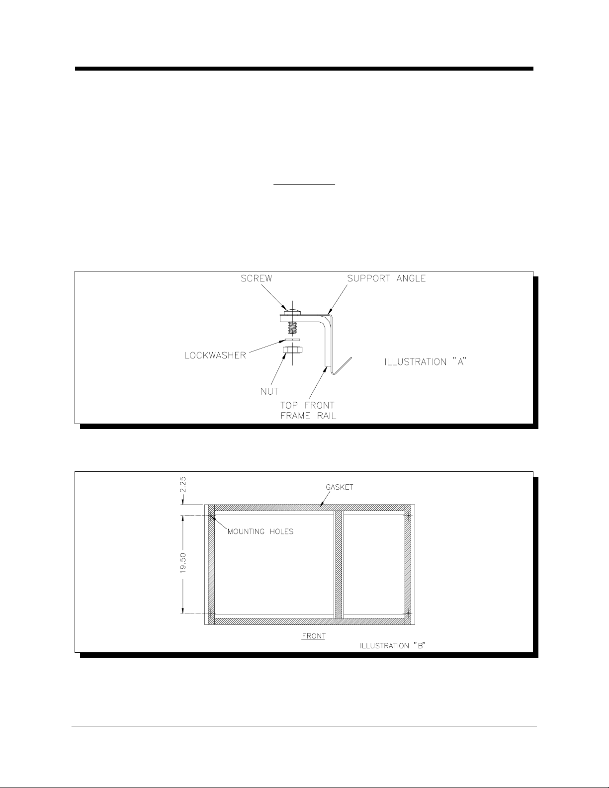
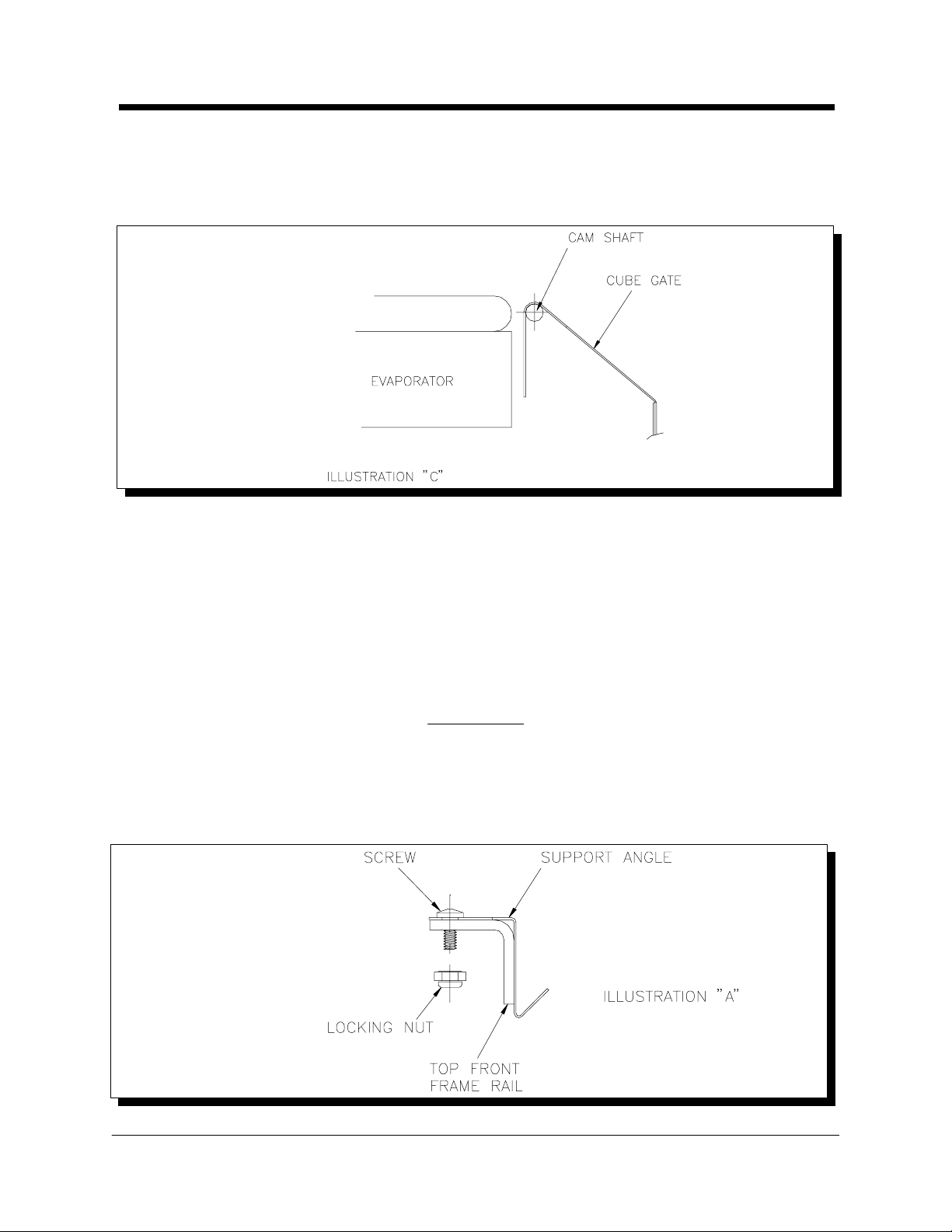
2. Mount inspection panel support angle to top front frame rail of lower (old GB
Classic) unit with #8-32 screw, nuts and lock washers provided. (See Illustration
"A")
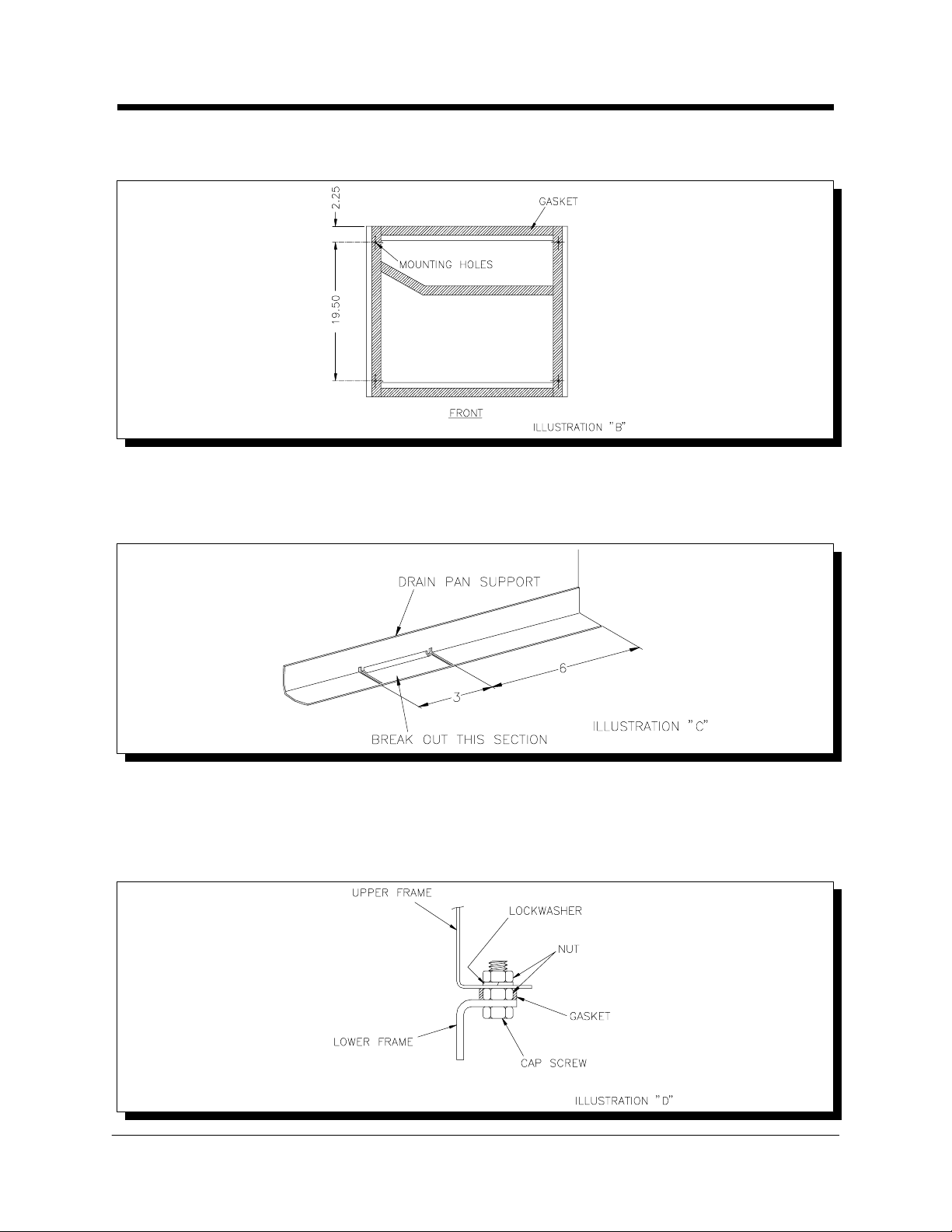
3. Apply gasket (supplied with kit) to the lower ice maker frame and cut to fit.
Pierce gasket where it covers the mounting holes. (See Illustration "B")
4. Install (4) 1/4-20 cap screws up through mounting holes of the lower ice maker
and secure with (4) nuts.
Kold-Draft® Service & Parts Manual Rev:3/02
- 23 -
Page 25
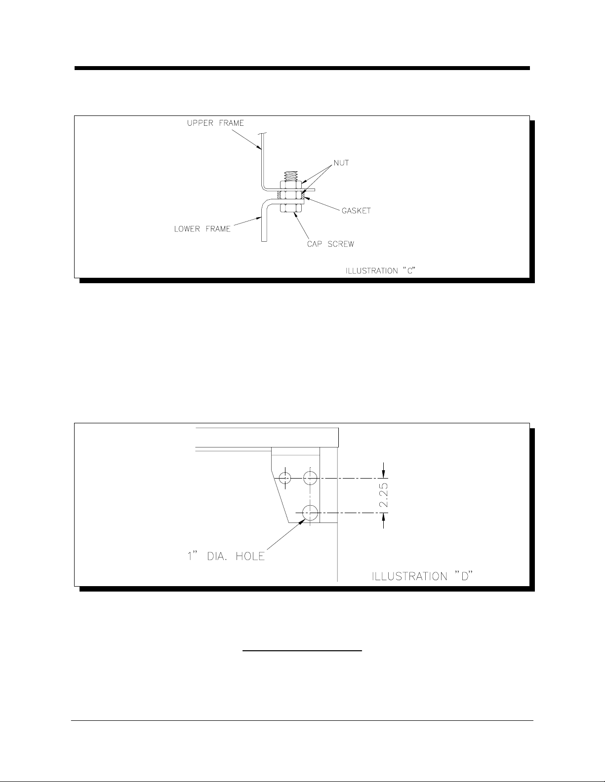
5. Position upper ice maker over lower unit and lower in place. Secure with (4)
GB Multiplexing Instructions
nuts. (See Illustration "C") CAUTION: Support upper unit unti l all fasteners are
secured.
6. Route upper ice maker bin thermostat capillary tube through grommeted hole in
the partition wall, down to the lower ice maker chute opening for positioning.
Keep capillary tube toward the front of the partition wall out of the path of falling
ice. Stacking a third ice maker will require a bin thermostat with a longer
capillary tube. Consult the factory for more information.
7. Install the upper ice maker drain pan and ice chute. Connect the drain hose
elbow assembly to the drain pan and route the drain hose through the rear of
the lower ice maker. If a 1" dia. hole has not been provided in the rear gusset of
the lower ice maker, it will have to be provided by the installer. (See Illustration
"D")
8. Install the Ice Chute (see instructions on Page 31), and side cabinet panels.
9. Follow start-up instructions to complete the installation.
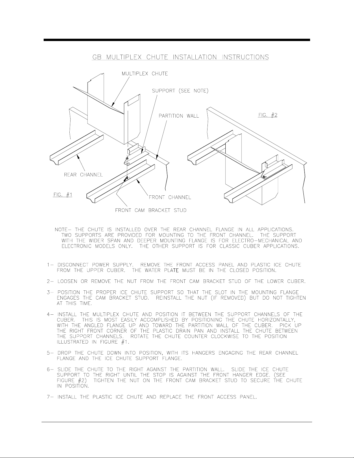
Ice Chute Installation
The stainless steel i ce chute provided with 102 1207 01 GB Model Stacking Kits is to
be installed in all except the TOP cuber in the stack. See the Ice Chute instal lation
instructions on Page 31 for details.
Kold-Draft® Service & Parts Manual Rev:3/02
- 24 -
Page 26
Section I
GT3XX
Multiplexing Instructions
{ Use a suitable lifting means and be careful of sharp edges.
NOTE: The next Two Sections only apply to GT3XX Cubers, the GT55X Cuber is
NOT stackable
CAUTION:
{ RISK OF PERSONAL INJURY, PROPERTY DAMAGE, EQUIPMENT FAILURE
OR FIRE.
{ Refer all maintenance to qualified personnel.
{ Never operate this equipment with covers, panels or other parts removed or not
properly secured.
Stacking new GT3XX Classic units above new GT3XX Classic units
NOTE: Please refer to Section II of these instructions for installing a new GT Classic
unit above an old GT Classic unit and Section III for install ing an old Classic (pre-1992
GT400, 500, 600) above a new GT Classic unit.
1. Remove cabinet panels from upper and lower ice makers.
2. Apply gasket (suppli ed with kit) to the lower ice maker frame and cut to fit.
(See Illustration "A")
3. Install (4) 1/4-20 cap screws up through mounting holes of the lower ice maker
and secure with (4) nuts. (See Illustration "B")
Kold-Draft® Service & Parts Manual Rev:3/02
- 25 -
Page 27
4. Position upper ice maker over lower unit and lower in place. Inst all lock washers
GT3XX
Multiplexing Instructions
and secure with (4) nuts. (See Illustration "B") CAUTION: Support upper unit
until all fasteners are secured.
5. Hang cube gate on lower ice maker cam shaft. (See Illustration "C")
6. Remove the standard drain pan/chute from the upper ice maker and replace
with the Multiplex model (supplied with kit). Connect the drain hose to the drai n
pan nipple, and route it down so that it spills on the lower ice maker drain pan.
Secure the hose with a clamp.
7. Route the upper ice maker bin thermostat capillary tube through the
grommetted hole in the right side wall, down to the lower ice maker chute
opening for positioning. Keep capillary tube toward the front of the side wall out
of the path of falling ice. Stacking a third ice maker will require a bin thermostat
with a longer capillary tube. Consult the factory for more information.
Section II
Stacking new GT3XX Classic units above old GT30X Classic units
1. Remove cabinet panels from upper and lower ice makers.
2. Mount inspection panel support angle to top front frame rail of lower (pre-1992
GT Classic) unit with #8-32 screws and nuts provided. (See Illustration "A")
Kold-Draft® Service & Parts Manual Rev:3/02
- 26 -
Page 28
3. Apply gasket (supplied with kit) to the lower ice maker frame and cut to fit.
GT3XX
Multiplexing Instructions
Pierce gasket where it covers the mounting holes. (See Illustration "B")
4. The new Classic unit drain pan support angle must be modified for use with
pre-1992 Classic units. Remove the standard drain pan/chute from the new
Classic unit. Locate the notched section of the support angle, clip the tabs and
break out of unit. (See Illustration "C")
5. Install (4) 1/4-20 cap screws up through mounting holes of the lower ice maker
and secure with (4) nuts.
6. Position upper ice maker over lower unit and lower in place. Inst all lock washers
and secure with (4) nuts. (See Illustration "D") CAUTION: Support upper unit
until all fasteners are secured.
Kold-Draft® Service & Parts Manual Rev:3/02
- 27 -
Page 29
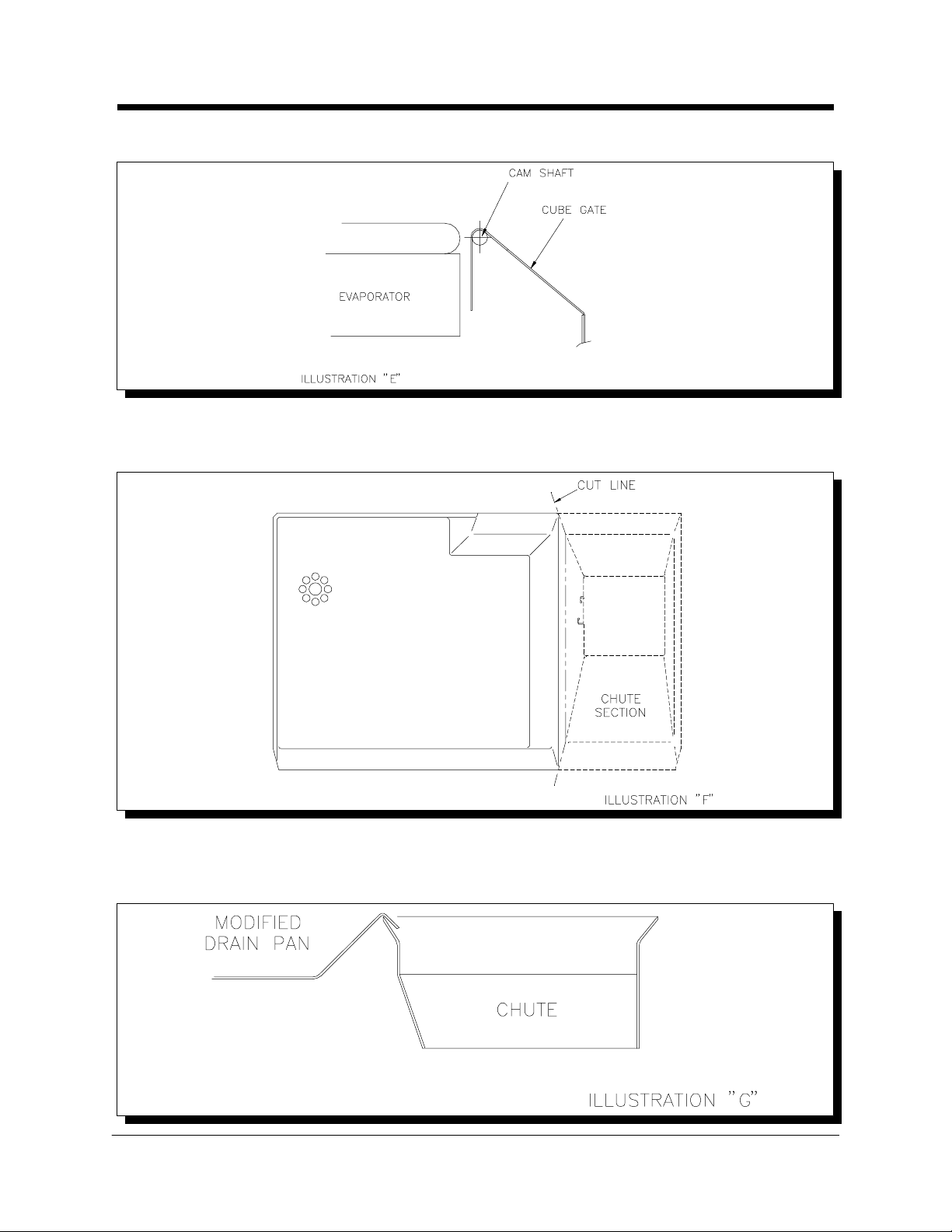
7. Hang cube gate on lower ice maker cam shaft. (See Illustration "E")
GT3XX
Multiplexing Instructions
8. Modify the multiplex chute (suppli ed with kit). Carefully separate the chute from
the drain pan with an utility knife and discard the chute section. (See Illustration
"F")
9. Install drain section in upper ice maker and move to the left side. Install chute
(supplied with kit) and position to the right side of the drain pan, under the drain
pan lip. (See Illustration "G") Route upper ice maker bin thermostat capillary
Kold-Draft® Service & Parts Manual Rev:3/02
- 28 -
Page 30
tube through grommetted hole in the partition wall, down to the lower ice maker
GT3XX
Multiplexing Instructions
chute opening for positioning. Keep capillary tube toward the front of the
partition wall out of the path of falling ice. Stacking a third ice maker will require
a bin thermostat with a longer capillary tube. Consult the factory for more
information.
10. Install the side cabinet panel s and follow start-up instructions i ncluded with the
ice maker to complete installation.
Section III
Stacking old (pre-1992) GT Classic (GT400, 500, 600) units above
new GT3XX Classic units
1. Remove cabinet panels from upper and lower ice makers.
2. Apply gasket (supplied with kit) to the lower ice maker frame and cut to fit.
(See Illustration "A")
3. Install (4) 1/4-20 cap screws up through mounting holes of the lower ice maker
and secure with (4) nuts. (See Illustration "B")
Kold-Draft® Service & Parts Manual Rev:3/02
- 29 -
Page 31

4. To allow for proper mounting, it is necessary to enlarge a 3/16" dia. hole in the
GT3XX
Multiplexing Instructions
bottom of the old GT Classic frame to 5/16" dia. (See Illustration "C")
5. Position upper ice maker over lower unit and lower in place. Install lock washers
and secure with (4) nuts. (See Illustration "B") CAUTION: Support upper unit
until all fasteners are secured.
6. Hang cube gate on lower ice maker cam shaft. (See Illustration "D")
7. Remove the standard drain pan and chute from the upper ice maker and
replace with the plastic drain pan and the multiplex chute. (supplied with kit)
Connect the drain hose to the drain pan nipple, and route it down so that it spills
on the lower ice maker drain pan. Secure the hose with a clamp.
8. Route the upper ice maker bin prove wire down to the lower ice maker chute
opening for positioning. Keep capillary tube toward the front of the side wall, out
of the path of falling ice.
Kold-Draft® Service & Parts Manual Rev:3/02
- 30 -
Page 32
Kold-Draft® Service & Parts Manual Rev:3/02
GB Multiplex Ice Chute Installation Instructions
- 31 -
Page 33

{
Operational Components
1992 and later models
{
Refer to the specific model wiring diagrams in addition to this text.
{
The following list of components and their functions is common to all models except
as noted in the text.
1. Compressor: All models are provided with a refrigerant compressor which is
rated for the electrical and refrigerant characteristics indicated on the
Nameplate located on the rear of the cuber.
2. Condenser: All models, except those which use a remote condenser (R), are
provided with a self-contained refrigerant condenser, either forced air (A) or
liquid (W) cooled, rated for the refrigerant type and pressure indicated on the
Nameplate. Remote condenser (R) models are intended for use with
remotely-installed forced air-cooled condensers meeting the requirements
indicated on the Nameplate.
3. Condenser Fan: Air cooled models (A) are provided with a condenser fan
motor and blade combination which have the proper air volume capacity for the
refrigeration system and minimum ventilation noise level. Note the installation
clearance requirements for each model.
4. Condenser Coolant Regulator Valve: Liquid cooled models (W) are provided
with a mechanical valve to regulate the flow of liquid coolant through the
condenser. This compensates for variations in the refrigeration load and
variations in coolant temperature to provide maximum efficiency. High-side
refrigerant pressure determines the valve modulation. Refer to the Controls
and Adjustments section for further information.
5. Heat Exchanger, Liquid-to-Suction: All models are provided with a
tube-in-tube heat exchanger which should sub-cool the liquid refrigerant
approximately 12} F. during the freeze cycle.
Rev:3/02 Kold-Draft® Service & Parts Manual
- 32 -
Page 34

6. Filter-Drier: All models are provided with a liquid-line filter-drier which is rated
Operational Components
for the refrigerant type and high-side design pressures indicated on the
Nameplate.
7. Thermostatic Expansion Valve (TEV): All models are provided with
mechanical TEV's which are suitable for the refrigeration load and the
refrigerant type indicated on the Nameplate. GB1220/1240/1250 Dual
evaporator models employ two TEV's. See the Controls and Adjustments
section for further information.
8. Evaporator: All models are provided with a plated copper evaporator, two
evaporators in GB1220/1240/1250 models, which determines the ice cube size
which will be produced. Each cube is formed in an individual cell with five
freezing surfaces. In order to change the size of ice produced, the evaporator,
and possibly the water plate, must be changed. The evaporator(s) is(are)
mounted horizontally with the open side down, and ice is harvested by gravity
without mechanical assistance. The small holes in part of the top surface allow
air in as the ice falls out. Refrigerant is carried by the serpentine coil of plated
copper tubing on the top surface of the evaporator.
9. Water Solenoid Valve: Each evaporator/water plate/tank section is provided
with a line-voltage solenoid valve which supplies all ice making and rinsing
water to the cuber. See the Controls and Adjustments section for details
regarding how and when the valve is energized.
10. Hot Gas (Defrost) Valve: All models are provided with a line-voltage hot gas
solenoid valve which routes the compressor discharge gas to the evaporator as
required, for harvesting ice or for cold-water effect compensation. See the
Controls and Adjustments section for details regarding how and when this
valve is energized.
11. Liquid Line Solenoid Valve: Remote condenser models (R) are provided with
a line-voltage liquid line solenoid valve which is energized only while the
'ICE-OFF-WASH' switch is in the 'ICE' position. The purpose of this valve is to
allow the low side to pump down during off periods. See the wiring diagrams
and the Control and Adjustments section for details regarding how this valve
is controlled.
12. Head Pressure Control Valve (Low Ambient): Remote condenser models (R)
are provided with a non-adjustable mechanical pressure regulating valve which
closes off the condenser liquid return and bypasses compressor discharge gas
to the receiver during cool ambient temperature operation (below 75} F.).
During this function, liquid refrigerant floods the condenser coil while the
receiver liquid pressure is maintained high enough for effective refrigeration.
REMOTE CONDENSER MODELS ARE NOT FACTORY CHARGED TO
THE MAXIMUM AND WILL LIKELY REQUIRE ADDITIONAL REFRIGERANT
CHARGE AT INSTALLATION. See the Installation Guidelines section for
determining the proper charge and for calculating the additional charge required
for the expected lowest ambient temperature operating conditions.
Kold-Draft® Service & Parts Manual Rev:3/02
- 33 -
Page 35

{
Operational Components
WARNING: RISK OF SERIOUS DAMAGE TO THE COMPRESSOR!
Insufficient refrigerant charge will result in repeated pump-down cycles until the
compressor overloads or fails.
13. Harvest Regulator Valve: Remote condenser models (R) are provided with a
non-adjustable mechanical pressure regulating valve. The purpose of this valve
is to maintain high-side refrigerant mass for adequate heat transfer when the
hot gas valve is open, if the discharge pressure falls below 150 psig. This valve
only functions as required, and it is not likely to open when the condenser
ambient temperature is above 75} F.
14. Quick-Connect Refrigerant Fittings: Remote condenser models (R),
Kold-Draft® remote condensers and Kold-Draft® remote line sets are provided
with re-sealable fittings for refrigerant line connections. Kold-Draft® condensers
and line sets are VAPOR-CHARGED only.
15. Strainer-Water Inlet: All models are provided with an in-line potable supply
water strainer. This strainer is not intended to remove supply water turbidity,
which is inherent to the water supply, but rather to protect the water solenoid
valve(s) from damage due to an unusual event, such as follows a water shut-off
for plumbing work. If the need for cleaning the strainer is frequent, an external
water filter should be provided. The strainer may be cleaned without
disassembly of tubing.
16. Receiver-Refrigerant: Liquid cooled (W) and Remote condenser (R) models
are provided with receiver tanks, which are rated for the refrigerant charge type,
amount and pressures indicated on the Nameplate. Air cooled models (A) do
not employ a receiver.
17. Check Valve-Receiver Inlet: Remote condenser models (R) are provided with
a check valve at the receiver inlet. The purpose of this valve is to minimize
refrigerant backflow to the condenser during harvest and off cycles and to
maintain receiver pressure during harvest for proper operation of the harvest
regulator valve with low condenser ambient temperatures.
18. Check Valve-Harvest Regulator Valve Inlet: Remote condenser models (R)
are provided with a check valve in the supply tubing to the harvest regulator
valve. The purpose of this valve is to avoid migration of high-side refrigerant to
the liquid line during off cycles, when the high-side pressure is lower than the
setting of the harvest regulator valve. Without this check valve, the pumpdown
controller (see the Controls and Adjustments section) would not function
properly.
19. Check Valve-Hot Gas Line: GB1220/1240/1250 Dual evaporator models are
provided with a check valve in the hot gas tubing to the Master (upper)
evaporator. The purpose of this valve is to prevent refrigerant migration from
the upper to the lower evaporator during freeze cycles, which can occur due to
gravity. Frost on the hot gas tubing indicates refrigerant migration from the
lower to the upper evaporator, which is due to refrigeration imbalance. See the
Service and Troubleshooting section for more details.
Rev:3/02 Kold-Draft® Service & Parts Manual
- 34 -
Page 36

20. Water Plate: All models are provided with a plastic water plate beneath each
Operational Components
evaporator. The flat top surface of the water plate is provided with holes for
injection of water into each evaporator cell and for return of unfrozen water to
the water circulation system. This surface forms the sixth surface of the cubes
and is spaced from the evaporator so that a thin, uniform web of ice is formed.
The cubes are connected together to promote harvest in one or more large
sections, rather than individually which would cause excessive melting and
require a much longer harvest time.
21. Water Tank: A plastic water tank, or sump, is attached to the bottom of each
water plate. The volume of this tank contains enough water for a single batch of
ice, along with some excess water to carry away the impurities from the water
supply. The impurities are excluded from the ice by the constant circulation
during the freezing cycle. Unfrozen water is returned to the tank, from the water
plate, during the freeze cycle. The excess water, with concentrated impurities, is
drained from the system each cycle along with the fresh water which rinses the
water plate while it is opening for harvest.
22. Water Pump: Each evaporator/water plate/tank section is provided with a water
pump. The purpose of this pump is to recirculate the ice-making water
constantly, through the water plate, during the freeze cycle. The pump does not
run during the harvest cycle. All water pumps are designed exclusively for the
application electrical requirements and ice maker type (GB/GT) to provide the
proper water circulation rate. See the Controls and Adjustments section for
details regarding how and when the pump is energized.
Kold-Draft® Service & Parts Manual Rev:3/02
- 35 -
Page 37

23. Actuator Motor and Cams: The opening and closing of the water plate for
Operational Components
freezing and harvesting cycles is accomplished by the actuator motor. The
connection between the actuator motor and water plate is through plastic cams
and springs. When the water plate is closed for freezing, the cam lever with the
spring attached is in the noon position with the spring slightly stretched, keeping
the water plate tight against the cam surface at the motor coupling. See the
Service and Troubleshooting section for alignment and adjustments. At the
beginning of a harvest cycle, the actuator motor runs counter-clockwise (CCW,
facing the cuber) and the cam surface forces the water plate away from the ice.
As the motor continues to run, the cam lever travels to the 7 O'Clock position
when the motor stops with the water plate open for harvesting the ice. After the
ice has been harvested, the actuator motor runs clockwise (CW) to turn the cam
levers back to the noon position for the next freeze cycle.
CAUTION: Overfreezing, so that more cam force is required to separate the
water plate from the ice causes undue component wear. See the Controls and
Adjustments and Service and Troubleshooting sections for proper
adjustments to avoid this condition.
Rev:3/02 Kold-Draft® Service & Parts Manual
- 36 -
Page 38

1. Bin Thermostat: The bin thermostat provides power to the 'ICE-OFF-WASH'
Controls and Adjustments
switch. See the GB & GT Cuber Installation Instructions for the proper
placement and securing of the bin thermostat capillary tube.
Adjustment of this control can be made with the 'ICE-OFF-WASH' switch (see
below) in the 'WASH' position to avoid unnecessary compressor cycling. While
holding some ice against the end of the capillary tube the cuber should shut
down within one minute. Turn the adjustment warmer (CCW) to shut down
sooner, or colder (CW) to delay shut down (may be necessary in cool ambients
to avoid premature shut down). Ideally, the shut down will occur after the ice
has harvested and before the water plate closes. This adjustment should be
checked with the ice storage area full and with the unit at typical ambient
temperature.
Note: The compressor control circuit in remote condenser models (R) is
supplied upstream from the bin thermostat in order to allow the low-side
pumpdown cycle during off periods.
2. High Temperature Shutoff Thermostat: Before October, 1996 some models
were provided with a high temperature shutoff thermostat on the suction line
near the compressor inlet. This control provides power to the bin thermostat and
to the compressor circuit pressure switches in remote condenser (R) models. If
the suction line temperature rises to 130} F. due to a refrigeration problem,
such as the hot gas valve mechanically stuck open, power will be shut off to all
operating components of the cuber including the compressor in remote
condenser models (R). This control will automatically reset when the suction
line cools to 110} F., restoring power to the operating components.
3. ICE-OFF-WASH Switch: The 'ICE' position connects power from the bin
thermostat to all control circuits, except the compressor circuit in remote
condenser (R) models, and to the respective electrical operating components
except the compressor motor (and condenser fan motor in self-contained air
cooled models) which is (are) powered by the contactor.
The 'WASH' position allows all electrical operating components to be powered
without the compressor running for in-place cleaning or test procedures (see
Kold-Draft® Service & Parts Manual Rev:3/02
- 37 -
Page 39

additional details under Pump-Down Controller, Relay-Hot Gas Control and
Controls and Adjustments
Relay-Rinse and Hot Gas Control).
The 'OFF' position (center) interrupts power to all control circuits, except the
compressor circuit in remote condenser (R) models, and to the respective
electrical operating components.
{
Warning: All cuber circuits are not de-energized when this switch is in the
'OFF' position. Disconnect power to the cuber before servicing.
4. Liquid Level Controller (LLC) and Water Level Probes: A clear plastic tube,
which contains three stainless steel probes and indicates the water level in the
circulation system, is located at the front of all models. The high and low level
probes sense the water shut-off level and harvest initiation level, respectively.
The common probe serves as a reference for the high and low level probes
since conductivity of low-voltage alternating current (AC) through the water
provides the signals. The high level probe de-energizes the water fill circuit
when contacted by water. The low level probe initiates harvest (during normal
operation) or energizes the water fill circuit (start-up or cleaning cycles when
the evaporator is warm) when the level of water is below this probe. Once the
water fill has been completed and the water fill circuit has been de-energized,
no further changes in the water fill or harvesting operation will be noted until the
level is below the low level probe. The LLC input and outputs are line voltage.
Note that both normally open (N.O.) and normally closed (N.C.) LLC
connections are used. The blue circuit, which powers the harvest initiate and
water fill circuits, is connected to common (COM). The black/green main power
circuit is connected to the N.O. terminal to power the blue circuit whenever the
LLC relay is energized, as during water fill and harvest initiation. The red
"defrost" circuit is connected to the N.C. terminal as a fail-safe circuit to avoid
water plate lockup in a partially-closed position.
5. Pump and Defrost Switch: The operation of each water pump is controlled by
a pump and defrost switch which is actuated by a tab or bolt on the side of the
water plate. The pump runs when the water plate is closed, and it stops as the
water plate opens. With the water plate open enough so that the pump is not
energized, the red circuit, which powers the water plate opening actuator motor
winding, is energized. If this switch is not actuated to start the pump before the
water plate is completely closed, the actuator motor will repeatedly re-open the
water plate. If the water plate closing is obstructed by ice which did not fall off,
the springs will stretch so that the cam may continue to rotate, but the water
plate tab or bolt cannot actuate the pump and defrost switch and the water plate
will re-open to clear the obstruction. This switch must be actuated to start the
pump when the spring-end of the front cam is between the 10 and 11 O'clock
position while rotating clockwise to close the water plate. If the water plate
springs have weakened over time, the water plate will not pull up tightly against
the front cam and the pump switch adjustment will be affected. Be sure that the
springs are not stretched, then if adjustment is necessary it is made by bending
the tab or adjusting the bolt on the water plate. Do not bend the switch lever, but
be sure that the tab or bolt engages the switch lever as the water plate closes.
The pump and defrost switch in all single evaporator models, and the Master
(upper) pump and defrost switch in dual evaporator models manufactured
between January, 1992 and March, 1996 is a two-pole switch. The second pole
provides power to the water solenoid valve through the black-to-yellow actuator
toggle switch circuit to rinse the water plate as it opens for harvest. Rinse will
not begin until approximately the same time as the pump stops, and the water
Rev:3/02 Kold-Draft® Service & Parts Manual
- 38 -
Page 40

solenoid valve will be de-energized as soon as the water plate is fully open only
Controls and Adjustments
during harvest cycles when the actuator thermostat, described later, is
switched cold.
Since March, 1996 all single- and dual-evaporator models employ ONLY
single-pole pump and defrost switches, and water plate rinse begins
immediately upon harvest initiation. See EB#96001 for details.
6. Actuator Thermostat: All models are provided with an actuator thermostat
which senses the evaporator temperature. During the freeze cycle the actuator
thermostat switches cold (at approx. +26} F. in its coldest adjustment) to set up
the electrical circuit for harvest, connecting the blue LLC output (COM), which is
not energized until the water level is below the low water level probe, to the red
circuit. No change in cuber operation will be evident at this time. After ice has
harvested this thermostat switches warm, above 50
}
F., connecting the water
plate closing and water fill circuits to the blue LLC output which is energized at
that time. Setting the actuator thermostat warmer will keep the water plate open
longer after the ice has dropped.
Note: At the full warm (CCW) adjustment the actuator thermostat is locked in
the cold switch contact position and will not reset warm, to raise the water plate,
regardless of evaporator temperature. This control should never be set warmer
than necessary to insure that all ice is out of the evaporator(s) before the water
plate(s) begin closing.
7. Cold Water Thermostat: All models except GT330/GT340/GT350 series are
provided with a cold water thermostat which senses the evaporator temperature
along with the actuator thermostat. In self-contained models, (A) or (W) except
dual evaporator models (before 9/96), this control connects the hot gas valve to
the blue LLC output when it is switched cold or to the red circuit when it is
switched warm. The red circuit is energized whenever the water plate is not fully
closed, and the blue circuit is energized from harvest initiation until completion
of the water fill. The hot gas valve will be energized throughout the harvest
cycle and until the water plate is completely closed and thereafter only if the
cold water thermostat trips cold during the water fill.
Remote condenser models (R), and all dual evaporator models before
September, 1996, do not have a red circuit connection to the cold water
thermostat, so that the hot gas valve may be de-energized when the water plate
is not fully closed but only if the cold water thermostat has reset warm. This
allows cycling of the water plate, for example to dump cleaning solutions,
without energizing the hot gas valve which would cycle the compressor in
remote condenser models (R) due to the low-side pump-down controller,
described later.
Note: The calibrations of the cold water and actuator thermostats may overlap.
When there is no red circuit connection to the cold water thermostat it is
necessary to provide a hot gas valve latching circuit until the actuator
thermostat switches warm to avoid the possibility of the hot gas valve being
de-energized before the water plate begins closing. This circuit is provided by
the hot gas control relay, or by the rinse and hot gas control relay in dual
evaporator models (before 9/96), described later.
The cold water thermostat additionally, acts as a foolproof
control in the event that the evaporator temperature decreases very rapidly
during the water fill due to very cold supply water, or if the water fill rate is
abnormally slow due to inadequate water supply or a restricted filter/strainer,
etc. Refer to the Cold Water Thermostat Cycle in the Sequence of Operation
Kold-Draft® Service & Parts Manual Rev:3/02
- 39 -
Page 41

section for the description of the cold water thermostat function in this case.
Controls and Adjustments
The proper adjustment is usually fully cold (CW). When supply
water is very cold, less than 50} F., and ice is being fully-formed (control stream
goes over the dam) or when the ice is not cleared from the water plate surface
by the rinse water due to water plate surface breakdown (also see Water Plate
Service section), the cold water thermostat may be adjusted warmer (CCW).
This will provide additional heat to the water, only during the fill cycle, to avoid
progressive freezing-up of the water plate which will result in early failure. A
warmer setting is recommended for remote condenser models (R) and all dual
evaporator models with cold supply water.
8. Actuator Toggle Switch: The travel of the actuator motor in all models is
controlled by the actuator toggle switch, which is tripped by a paddle on the
motor gearbox output shaft. When the water plate is fully closed, as during the
freeze cycle, the switch lever is in the 'up' position. This connects the water
plate opening winding of the motor to the red circuit, and also connects the
water solenoid valve coil to the water plate rinse circuit. When the water plate
is fully open, as during the harvest cycle, the switch lever is in the 'down'
position. This connects the water plate closing winding of the actuator motor
and the water solenoid valve coil to the warm actuator thermostat circuit, and
also connects the red circuit to the black/green main power circuit which powers
the fail-safe circuit, described under Liquid Level Controller.
The paddle which trips this switch may be bent slightly to insure that the
water plate stops in its widest open position. This is necessary for proper
harvest of half-cubes (HK). In dual evaporator models only, the paddle may be
bent to provide slight overtravel, toward the 1 O'clock position (not
recommended with NEW STYLE Actuator Motors), when the Master (Upper)
water plate closes, for a slight additional synchronization time. See additional
details under Timer-Master Actuator Motor Delay.
9. Capacitor(s)-Actuator Motor: All actuator motors employ a capacitor between
the two windings to determine the direction of rotation when the motor is
energized.
Models manufactured between approximately 1964 and 5-1-95 employ the
OLD STYLE actuator motor which requires a 1.5 mfd. capacitor for this purpose.
These motors were all rated 115 Volts, and in 208-240 Volt applications, where
an internal transformer was not employed to provide 115 Volts to the actuator
motor, a second capacitor in series with the motor winding, white wire, was
employed for voltage reduction. The value of the second capacitor was 1.5 mfd.
for 220-240 Volt/50 Hz. models, or 2.0 mfd. for 208-230 Volt/60 Hz. models.
Models manufactured after 5-1-95 employ a NEW STYLE actuator motor
which is rated either 115 Volts or 230 Volts and requires only one capacitor
installed between the windings of each motor for direction of rotation. The 115
Volt motor capacitor is rated 4 mfd., and the 230 Volt motor capacitor is rated 1
mfd. Replacement Actuator Motor kits after June, 1995 are provided
with only the NEW STYLE actuator motors. Refer to the Service and
Troubleshooting section to determine which style is installed and the
respective troubleshooting information.
10. Contactor: All models are provided with a contactor which carries the
compressor load, and the fan motor load in air cooled models (A). The contactor
coil is rated for line-voltage, and the contacts are rated for definite purpose
applications (FLA and LRA).
Rev:3/02 Kold-Draft® Service & Parts Manual
- 40 -
Page 42

11. High Pressure Cutoff: All models are provided with a high pressure cutoff
Controls and Adjustments
controller in the compressor discharge line which opens the contactor coil
circuit on high-side pressure rise to 400 (435 after December, 1995) psig. The
controllers have been MANUAL RESET type since approximately 3-93.
12. Pump-Down Controller: All remote condenser models (R) are provided with a
pump down controller in the compressor suction line which opens the contactor
coil circuit when the low-side pressure decreases to 5 to 10 psig. The intent of
this controller is only to pump the low-side down during off periods, but a
shortage of refrigerant in the system will cause it to function during freeze
cycles. See the Installation Guidelines for charging requirements for these
models.
13. Relay-Hot Gas Control: (Single evaporator remote condenser (R) models, and
Relay 2 in Dual evaporator R models beginning in September, 1996) This
controller is shown in the ALTERNATE WIRING on the wiring diagrams. Its
purpose is to isolate the hot gas valve circuit from the red circuit so that the hot
gas valve is not energized any time the water plate is not fully closed unless the
actuator or cold water thermostat is switched cold. This allows checking of the
actuator motor operation and dumping of cleaning solutions without cycling the
compressor due to the pump-down controller with the 'ICE-OFF-WASH' switch
in the 'WASH' position. See Cold Water Thermostat for more details.
14. Relay-Rinse and Hot Gas Control: (All Dual evaporator models before
September, 1996) This controller serves the same purpose as the hot gas
control relay, see above. In addition, it serves to isolate the two actuator motor
water plate closing winding circuits from each other and from the water plate
rinse circuit to insure water plate synchronization. See Timer-Master Actuator
Motor Delay description and Service and Troubleshooting section for more
details.
15. Relay-Water Plate Synchronization: (All Dual evaporator models beginning
in September, 1996) This relay is designated as Relay 1, and its purpose is to
only allow the Slave actuator motor to be energized depending upon the
position of the Master actuator motor/toggle switch for more reliable
synchronization (see EB #96003).
16. Timer-Master Actuator Motor Delay: (Dual evaporator models, Upper only)
This controller is only employed with NEW STYLE actuator motors, after 5-1-95.
It delays the starting of the Master (Upper) actuator motor for 2 seconds in
either direction during normal ice making operation. The Slave (Lower) actuator
toggle switch must be tripped BEFORE the Master in order to properly
synchronize the water plates. There is also an interconnection between the
actuator motor circuits which stops the Slave motor in the water plate closed
position until the Master motor completes closing its water plate. See the
Service and Troubleshooting section for more details.
Kold-Draft® Service & Parts Manual Rev:3/02
- 41 -
Page 43
{
Sequence of Operation
The following sequence begins with the cuber as shipped from the factory with the
Water Plate(s) closed and ready to begin a normal ice making cycle.
WATER FILL CYCLE
After about a pint of clean water is added to each water tank (start-up only) with the Bin
Thermostat warm, power is turned on by moving the 'ICE-OFF-WASH' Switch to
either 'ICE' (left side) or 'WASH' (right side) position to observe the water fill cycle.
When the Actuator Thermostat is switched warm, Evaporator above +60
}
F., the
Water Solenoid Valve will be energized only until the water level reaches the High
Water Level Probe, and the Water Pump will run when the Water Plate is closed.
Note: If the Actuator Thermostat is switched cold (Evaporator temperature is lower
than +26
}
F. or has not risen to above +60
}
F. after a harvest, or if the Thermostat is
locked-out in its WARMEST adjustment) the Water Plate will begin to open as soon as
power is applied, but the Water Solenoid Valve will not be energized until after the
Water Pump stops as the Water Plate opens if the cuber has a double pole pump
switch rinse circuit (see Controls and Adjustments section).
Remote Condenser Models (R) Only: The Compressor is connected directly to the
line through the High-Pressure Cutoff and the Pumpdown Controller, so the
Compressor may cycle with the 'ICE-OFF-WASH' Switch in any position as soon as
power is applied.
COLD WATER THERMOSTAT CYCLE (except GT33X/GT34X/GT35X)
With the refrigeration unit running ('ICE-OFF-WASH' Switch in the 'ICE' position) the
Evaporator will begin to cool as soon as power is applied. If the Evaporator
temperature lowers to approximately 45} F. during the water fill cycle, the Cold Water
Thermostat will switch cold and the Hot Gas Valve will be energized until the
Evaporator temperature rises above 50
}
F. or until the water fill is completed, then
refrigeration resumes.
Note: This is a normal function when the water supply temperature is lower than 50} F.,
however it may occur if the water fill rate is abnormally slow due to low water supply
pressure, undersized water supply line, or restricted Water Strainer or external filter.
With proper water supply characteristics the water fill should complete in approximately
1 minute for (K) cube or 1-1/2 minutes for (C) or (HK) cube size models.
FREEZE CYCLE
Once the water fill cycle has been completed, the Water Solenoid Valve will remain
de-energized until during the following harvest cycle. The Cold Water and Actuator
Thermostats switch to their cold contacts as the Evaporator temperature lowers to
their settings, however no change in the cuber functions will be noted at these times.
The water level in the Liquid Level Probe Tube lowers as the water is frozen, but no
additional water will be introduced during the freeze cycle. The Control Stream runs
continuously during the freeze cycle with the water returning to the Water Tank
through the hole which can be seen through the Control St ream Box to the left of the
Dam in the Box.
Note: No water, other than condensation, should dri p or run to the Drain Pan from the
Control Stream or from the Water Tank during the freeze cycle.
Rev:3/02 Kold-Draft® Service & Parts Manual
- 42 -
Page 44

CONTROL STREAM CYCLE
Sequence of Operation
The water level in the Liquid Level Probe Tube must get below the level of the Low
Water Level Probe, and both the Cold Water and Actuator Thermostats must have
switched cold to initiate the harvest cycl e. If there is an excess of water in the Water
Tank, the Water Pump outlet pressure increases when the Evaporator cells are full,
and the Cont rol Stream rises and flows over the Dam to the Drain Pan to evacuate
the Liquid Level Control Tube.
Note: The Control Stream is a "safety valve" to insure the ability to initiate harvest
rather than an ice quality control, and it should never need to go over the Dam for more
than 15 seconds before harvest begins. Setting the Water Level Probes so that the
water in the Liquid Level Control Tube gets below the Low Water Level Probe to
initiate harvest without the Control Stream running over the Dam, leaving a small
"dimple" in the cubes, will result in increased ice making capacity and longer Water
Plate life.
HARVEST INITIATION
When the water level in the Liquid Level Probe Tube is below the Low Water Level
Probe and the Cold Water and Actuator Thermostats are switched cold, the Liquid
Level Control output energizes the blue circuit at the COM terminal. Power is provided
to the Hot Gas Valve through the Cold Water T hermostat, and to the Water Plate
opening winding of the Actuator Motor through the Actuator Thermostat and the
Actuator Toggle Switch. The Evaporator begins to defrost, and the Water Plate
begins to open immediately while the Wat er Pump conti nues to run for a few seconds.
The Water Solenoid Valve is not energized until approximately the same time the
Water Pump stops when the Water Pla te is sl ightly open and the Pump and Defrost
Switch Lift Tab/Bolt on the side of the Water Plate allows the Switch lever to drop if
the cuber has a double pole pump switch rinse circuit (see Controls and Adjustme nts
section). The Water Plate rinse is terminated when the Actuator Toggle Switch is
tripped DOWN in the Water Plate OPEN position (see wiring diagrams for full rinse
option).
Note: Dual evaporator models require that the Slave (lower) Actuator Toggle Switch
be tripped before the Master (upper) in both Actuator Motor directions to insure
synchronization. This was accomplished by using a slower motor in the Master until
5-1-95, and by a Delay Timer in the Master motor circuit thereafter. The three-pole
Rinse and Hot Gas Control Relay, or the Water Plate Synchronization Relay in
retrofitted per EB #96003 or 9/96 and newer models, isolates the closing windings of
the Actuator Motors from each other. This prevents the Slave Water Plate from
beginning to close while the Master Water Plat e finishes opening in the harvest cycle,
when the Actuator Thermostat is cold, due to the power in the rinse ci rcuit until the
Master is fully open.
HARVEST CYCLE
As long as the Actuator Thermostat remains cold, the Water Plate(s) remain in the
open position with the Water Solenoid Valve(s) de-energized. The Hot Gas Valve
remains energized, and the Evaporator(s) become warm enough to release the ice
which drops by gravity into the ice storage area.
Kold-Draft® Service & Parts Manual Rev:3/02
- 43 -
Page 45

HARVEST TERMINATION
Sequence of Operation
After the ice is out and the Evaporator(s) warm to the reset temperature of the
Actuator Thermostat, up to +60} F., the Actuator Motor(s) will be energized to close
the Water Plate(s), and the Water Solenoid Valve(s) will be energized to begin the
water fill for the next ice-making cycle. The Hot Gas Valve always remains energized
until the Water Plate is fully closed in all self-contained (A) and (W) models except
dual evaporator models prior to 9/96 which have not been retrofitted per EB
#96003.
Note: The Hot Gas Control Relay in remote condenser (R) models, or the Rinse and
Hot Gas Control Relay in all pre-9/96 dual evaporator models, allows the Hot Gas
Valve to be de-energized as soon as the Cold Water Thermostat switches warm,
above +50} F., even before the Water Plate(s) is (are) fully closed, but only after the
Actuator Thermostat switches warm and the Water Plate(s) begin closing.
PUMP START
As the Water Pla te cl oses, the Lift Tab/Bolt on the Wat er Pla te must raise the Pump
and Defrost Switch lever to start the Water Pump before the Water Plate is fully
closed. The Tab/Bolt should be adjusted so that the Pump starts when the Cam is
between 10 and 11 O'clock.
Note: in dual evaporator models, the Slave (lower) Wat e r Plat e is ahead of the Master
(upper) Water Plate so that the Slave Pump should start before the Master Pump
starts.
CONTINUATION-NORMAL
When the Cam is at the 12 O'clock position, the Paddle on the Actuator Motor output
shaft will trip the Actuator Toggle Switch up. If the Water Plat e has completely closed
and the Wate r Pump has started, the Actuator Motor will stop with the Water Plat e
closed and the cycle will repeat beginning with WATER FILL CYCLE.
Note: Since the Slave (lower) Water Pla te is ahead of the Master (upper) Water Pla te
it will be fully closed and trip its Actuator Toggle Switch before the Master Water
Plate is fully closed. An interconnection between the Actuator Motors causes the
Slave to stop until the Master completes closing and trips its Actuator Toggle Switch.
See Actuator Motor in Service and Troubleshooting section for circuit explanations.
ABNORMAL-WATER PLATE RE-OPENS
If the Pump and Defrost Switch is not properly actuated, due to mis-adjustment, weak
springs, or an obstruction to the Water Plate travel, such as ice which did not slide off
of the plate, the Actuator Motor will immediately reverse and re-open the Water Plate.
Additionally, if the cuber has a double pole pump switch rinse circuit (see Contro ls and
Adjustments secti on and EB #96001) should the Wate r Pump start but the rinse pol e
of the Pump and Defrost Switch not break, either due to mis-adjustment or to a
defective switch, before the Actuator Toggle Switch is tripped, the Water Plate will
remain closed until the water fill is completed and then re-open as soon as water
touches the High Water Level Probe.
Rev:3/02 Kold-Draft® Service & Parts Manual
- 44 -
Page 46

SHUTDOWN-BIN FULL
Sequence of Operation
When the l evel of ice reaches the Bin Thermostat capillary tube, the ice maker stops
automatically, and it remains off until the Bin Thermostat warms up when the ice level
is lowered.
Note: In remote condenser models (R), the Compressor continues to run after Bin
Thermostat shutdown until the low-side is pumped down to the setting of the
Pumpdown Controller. This pressure should be between 5 and 10 psig and must
never be vacuum.
SHUTDOWN-HIGH PRESSURE
All models are provided with a High Pressure Cutoff which interrupts power only to
the Compressor, and to the Condenser Fan Motor in air cooled (A) models, when the
high-side pressure rises to the cutoff setting. The High Pressure Cutoff requires
manual resetting to restore power in all models manufactured after 3-93.
SHUTDOWN-HIGH TEMPERATURE
If the suction line temperature near the Compressor should rise to 130o F in cubers
equipped with a High Temperature Shutoff Thermostat (see Controls and
Adjustments section), power will be shut off to all operating components of the cuber.
This control will automatically reset when the suction line cools to 110o F.
'WASH' CYCLE
All of the cuber's operational components except refrigeration are able to function with
the 'ICE-OFF-WASH' Switch in the 'WASH' position. Simply placing thi s Switch in the
'WASH' position does not complete the cleaning and sanitizing of the cuber. The
instructions for cleaning are on a label inside the front cabinet panel of the cuber, in the
Preventative Maintenance section of this manual, and in the cuber instructions.
Note: The frequency of the need for cleaning is determined by the supply water
characteristics. The cuber should be cleaned no less frequently than once each 6
months, and it may require more frequent cleaning. The requirement for sanitizing
frequency may be contained in local health code regulations.
Kold-Draft® Service & Parts Manual Rev:3/02
- 45 -
Page 47

ACTUATOR MOTOR - DESCRIPTION & TEST PROCEDURE:
Service and Troubleshooting
The actuator motor is a P.S.C. type with two windings in the coil and three power
leads. The white wire is common to both windings, and the colored wires are connected
to the actuator toggle switch and to a small capacitor. Power is supplied to one winding
at a time by the actuator toggle switch, and the capacitor changes the voltage and
phase to the other winding to determine the direction of motor rotation. Dual evaporator
models are provided with an extra circuit for s ynchronization of the motors which will be
described later.
Note: There are two different types of actuator motors since May, 1995. The OLD
STYLE motor has an end cover which completely covers the windings, and an ex ternal
drift stop is required. The NEW STYLE motor does not require the external drift stop,
and the coil windings are visible.
All OLD STYLE motors are rated 115 volts, and a second capacitor, in series with the
common winding lead (white wire), is provided in 208-230 volt/60 hz. (2.0 mfd/240 Vac)
and 220-240 volt/50 hz. (1.5 mfd/240 Vac) to reduce l ine voltage to the motor in 1992
and later models which do not have an internal transformer for this purpose. The
colored wires are always gray and yellow, and the direction capacitor is always 1.5
mfd/240 Vac.
The NEW STYLE (since May, 1995) motors are rated for 115 or for 230 volts and
never require two capacitors.
The 115 volt NEW STYLE motor colored wires are black and yellow, and the reversing
capacitor is 4.0 mfd/250 (or greater) Vac.
The 230 volt (50/60 hertz) NEW STYLE motor colored wires are red and yellow, and
the reversing capacitor is 1.0 mfd/370 (or greater) Vac.
Only the NEW STYLE actuator motors will be available after June, 1995. Replacement
of OLD STYLE with NEW STYLE actuator motors requires adaptation provided with kits
for the various applications. Refer to the application list following this text for
identification of the kits and wiring instructions.
CAUTION: Do not remove the outboard rotor bearings from any NEW STYLE motor.
Replacement motor parts (coil, rotor, etc.) are not available, and removal of the bearing
may cause damage.
Both OLD STYLE and NEW STYLE actuator motors should produce enough output
torque so that it is difficult to stall the cam with your finger. if not, the self-aligning
bearings may have been jarred out of alignment. Tap on the gearbox with a small
hammer or equivalent while the motor is running in both directions to re-align the
bearings. It is good practice to do this on every new installation, or with any motor
replacement, to correct for mis-alignment due to shipping or handling.
OLD STYLE motors are impedance protected to prevent unsafe overheating. These
motors will get very hot in the event of a stalled condition or in continuous operation
(such as pump switch mis-adjustment with water plate continuously opening and
closing), however power to the coil windings is not interrupted by a protective device.
NEW STYLE motors are provided with a thermal protector in the windings which will
interrupt power if its trip temperature is reached. If a NEW STYLE motor is hot and not
running, wait for the motor to cool enough to reset the protector before performing any
motor/capacitor tests.
If either type motor runs continuousl y, repeatedly tripping the actuator toggle switch,
but the water plate does not move, a cam pin is broken or missing.
Proper cam travel, viewing the water plate spring connection, is as follows:
ƒ Water plate closed, cam stopped at noon position with actuator toggle swit ch lever
in the 'up' position.
Rev:3/02 Kold-Draft® Service & Parts Manual
- 46 -
Page 48

ƒ Water plate opening, cam rotates counter-clockwise from noon to 7 O'clock
Service and Troubleshooting
position with the actuator toggle switch lever in the 'up' position.
ƒ Water plate fully open, cam stopped at 7 O'clock position with actuator toggle
switch lever in the 'down' position.
ƒ Water plate closing, cam rotates clockwise from 7 O'clock position to noon
position with the actuator toggle switch lever in the 'down' position.
Dual Evaporator Models Only
Dual evaporator cubers are provided with Master (upper) and Slave (lower) ice making
sections which must be synchronized for proper operation. In order to synchronize the
water plates without repeated opening and closing, the Slave actuator switch must be
tripped ahead of the Master actuator switch in both opening and closing the water
plates. The method to accomplish this is different between OLD STYLE and NEW
STYLE actuators motors, and changes with NEW STYLE motors occurred in
September, 1996. The proper wiring diagram must be used when troubleshooting.
CAUTION: Both actuator motors must be the same type - OLD STYLE or NEW
STYLE.
OLD STYLE Actuator Motors (Original in GB1224 and GB1225 Models only):
The Master (upper) motor is provided with a special rotor to produce a slower output
speed than the Slave (lower) motor. The special rotor is identified by an orange dot on
the outboard endplate of the rotor laminations.
If the Slave unit is not approximately 4 to 10 seconds ahead of the Master in both
directions:
‚ Tap the gearboxes to be sure that the bearings are aligned
‚ Check the drift stop tightness (only very slight pressure between the plastic button
and the end of the rotor shaft is needed)
‚ Be sure that the Master motor has the special rotor
‚ Eliminate binding in the cam shaft bearing brackets and/or water plate springs
(excessive front bearing bracket shimming will cause binding)
‚ Check the voltage across the motor direction capacitor per the following table if
necessary.
If all of these items check out the problem is in the gearbox, and motor replacement
will be required.
NEW STYLE Actuator Motors:
The Master (upper) and Slave (lower) motors are ident ical and should run at the same
speed. A timer is provided in the Master motor circuit to delay the start of this motor for
approximately 2 seconds, giving the Slave a head start toward tripping its actuator
switch.
If the Slave actuator switch is not tripped before the Master, first be sure that the
Master time delay is working, then:
‚ Tap the gearboxes to be sure that the bearings are aligned
‚ Eliminate binding in the cam shaft bearing brackets and/or water plate springs
‚ Check the voltage across the motor direction capacitor per the following table if
necessary.
If these items check out and the Master motor runs faster than the Slave so that it
overcomes the delay time and trips its switch ahead of the Slave, swap the motors.
Do not disassemble either motor.
Kold-Draft® Service & Parts Manual Rev:3/02
- 47 -
Page 49

All Actuator Motors (Dual Evaporator Models):
water plate is fully closed by
preventing it from being energized
before the Master
Service and Troubleshooting
In opening the water plates for harvest with the actuator thermostat switched cold there
is no power in the water plate closing circuit, so the water plates will both stop in the
fully-open position. However, if the Master (upper) actuator switch is tripped first (see
above) the Slave (lower) may stop before its switch is tripped. If so, after harvest the
Master will close but the Slave will remain open until the Master closes completely and
trips its switch. Then the Master will re-open and the Slave will finish opening then
close (pre-9/96), stopping when fully-cl osed until the Master re-closes. This results in
wasted cycle time, and the Slave will be overfilled with water, but no damage is caused.
In normal harvest operation, both water plates open full y and both actuator switches
are tripped to the 'down' position until the actuator thermostat switches warm. Then
both water plates begin closing (Master begins closing after time delay with NEW
STYLE m otors), the Slave actuator switch is tripped 'up' and the Slave motor stops until
the Master finishes closi ng. Both water plates should remain fully closed until the next
ice harvest. If not, there may be an obstruction (ice stuck on water plate), or a pump
switch may be out of adjustment.
Slave Motor Stopping Circuit:
The Slave (lower) motor stopping circuit before September, 1996 is the black wire
from the Slave actuator switch to the yellow Master (upper) actuator motor winding
wire. In normal operation, this circuit functions only during the time required to finish
closing the Master water plate after the Slave is fully closed. However it can also stall
the Slave motor abnormally, as described above, if the Master actuator switch is
tripped first in the water plate opening sequence. Following is the circuit rationale:
In the normal harvest cycle water pl ate opening sequence with the actuator thermostat
switched cold, Relay 1 (Rinse and Hot Gas Control Relay) coil i s not energized. The
yellow/orange circuit which powers this coil from the actuator thermostat warm contact
also supplies power through the normally open (N.O.) contacts to the yellow and
orange Master and Slave, respectivel y, actuator switches for closing the water plates.
Therefore both water plates stop fully open for harvest unl ess there is a fault. The red
circuit, which powers the actuator motors in water plate opening, is initi ally energized
by the LLC (liquid level control) output through the cold actuator thermostat. This circuit
may also be energized by either pump and defrost switch (to re-open the water plates
in the event of an obstruction, or to dump cleaning solution), and i t is kept energized
through either or both actuator switches in the 'down' position.
When the Slave actuator switch is tripped 'up' with its water plate fully closed, the red
circuit is still energized from the Master actuator switch which has not yet been tripped
'up'. The Slave motor is now being powered in the opening direction, but the closing
direction winding is also being powered by the black wire circuit from the yellow Master
motor to the Slave actuator switch. With both windings powered from the line, the motor
"stalls" in electrical equilibrium.
Note: During water plate opening with the actuator thermostat switched warm, such as
when dumping cleaning solution or re-opening due to an obstruction, neither water
plate should stop in the fully-open position. With NEW STYLE actuator motors the time
delay in closi ng is canceled, but the Slave water plate should begin closing before the
Master completes opening so that the closing delay is not needed for synchronization.
Beginning in September, 1996 Relay 1 is designated as the SYNCHRONIZATION
RELAY, and Relay 2 (HOT GAS CONTROL RELAY) is added ONLY IN REMOTE
CONDENSER MODELS as in all single evaporator remote models. Relay 1
prevents the Slave actuator motor from closing its water plate before the Master water
plate is fully open, and from opening or re-opening its water plate before the Master
Rev:3/02 Kold-Draft® Service & Parts Manual
- 48 -
Page 50

actuator switch has been tripped to its respective posi tion regardless of evaporator
Service and Troubleshooting
on the white
motor
lead. If power is OK:
Winding open
position, 0 v. in the other position
Winding open
AND>
position, 0 v. in the other position
Change capacitor.
Good
Open
"B" from table
tightness. Change motor if all OK.
temperature. The time delay always occurs before the Master plate begins
closing, but not upon re-opening due to an obstruction, etc.).
Between late-1995 and September, 1996 a field-installed circuit modificati on kit was
available on an experimental basis. This kit included an additional relay, RELAY 2,
and re-wiring of the actuator motor interconnecting circuit. This Relay 2 is different
from the September, 1996 changes. No further information regarding this
modification is published in this manual. Contact the factory if you have any
questions.
Kits are available to retrofit older models to the September, 1996 circuits. Refer
to EB #96003 for details.
Actuator Motor Electrical Tests
The following tests are for troubleshooting the actuator motor and related circuits:
Use an AC voltmeter set for proper range. Voltages in the tables are measured across
the motor reversing capacitor (between the colored motor lead wires).
> If there is no i ce in the evaporator(s) and the water plate(s) i s (are) not fully cl osed
with the pump(s) running AND the actuator switch(es) tripped UP, the actuator motor(s)
should be running. If not, be sure that there is power to the motor(s) and that it (they)
is (are) not off due to high temperature (NEW STYLE). Always refer to the proper
wiring diagram when troubleshooting.
> In dual evaporator models if only one motor appears to be running as it should, be
sure that you understand the synchronization circuit (see text).
> For OLD STYLE motors in 208-230/60 or 220-240/50 CLASSIC cubers, the voltage
between the white motor lead (connected to the voltage reduction capacitor) and the
colored lead (gray or yellow) being powered by the actuator switch must be 90 to 130
volts. This varies with li ne voltage, and if not within these li mits the motor(s) may not
provide adequate performance. Be sure that the proper capacitor is installed (see
text).
> Motor winding resistance's at 75o F out of the circuit are as follows:
All OLD STYLE motors, white to gray or yellow, approximately 450 ohms.
NEW STYLE 115 volt motors, white to black or yellow, approximately 95 ohms.
NEW STYLE 230 volt motors, white to red or yellow, approximately 400 ohms.
Voltages for test table below
Actuator Motor Style "A" "B"
OLD STYLE, ALL 180-240 90-130
RemedyMotorCapacitorVoltage Reading
GoodGood"A" from table
"B" from table in one actuator switch
0 v. in both positions EXCEPT DUAL
EVAP. SLAVE DURING NORMAL STALL.
Be sure there is power to the motor ("B"
from table) by leaving one probe on either
capacitor lead and placing the other probe
Kold-Draft® Service & Parts Manual Rev:3/02
Open
Good"A" from table in one actuator switch
Shorted
OR>
Both Motor
Windings open
Tap gearcase to align bearings; check
cam shaft for binding; check drift stop
Change both motor and capacitor.One Motor
Change motor.One Motor
Disconnect motor from circuit and
test winding resistance's (see text). If
normal, change the capacitor, and if
erratic change the motor.
- 49 -
Page 51

Service and Troubleshooting
"New" 230 V. Actuator Motor Capacitor Styles
There has been a greater than normal number of failures of the actuator motor
reversing capacitors employed with NEW STYLE 230 volt actuator motors in dual
evaporator cubers. Although this style of capacitor is very convenient, with integral
mounting tab and quick-connect terminals, the dual-evaporator cuber application
requires a more durable capacitor.
Beginning with production dual evaporator cubers approximately December 1, 1995,
followed by 102 1238 02 motor kits and 102 1241 02 replacement capacitor kits, the
style of the actuator motor reversing capacitor was changed to an oval tubular
capacitor. It has un-insulated axial lead wires and is mounted with a cable tie in place
of the original style capacitor. Replacement capacitors will be mounted with the same
mounting screw as the original capacitors, and insulation tubing will be provided to
insulate the lead wires. The different styles are illustrated below.
Note: This change was never made in factory-production single evaporator
cubers. Beginning in September, 1996, a more robust capacitor with terminals
(similar to "OLD STYLE" as shown below) was employed in ALL models with
NEW STYLE 230 volt actuator motors until Feb., 2001 when the tubular capacitor
(“NEW STYLE” as shown below) was re-instated in all dual evaporator cubers, as
well as 102 1241 02 replacement capacitor and 102 1238 02 230 volt motor kits.
Actuator Motor Reversing Capacitor Styles for NEW STYLE 230 Volt Actuator Motors
Following are the instructions provided with replacement actuator motor kits for
replacing OLD STYLE with NEW STYLE actuator motors. Note that only the OLD
STYLE capacitor is shown in the illustrations.
Rev:3/02 Kold-Draft® Service & Parts Manual
- 50 -
Page 52

Service and Troubleshooting
Actuator Motor Replacement Instructions for
proceeding.
102 1238 01 115 V.-60 Hz. or 102 1238 02 230 V.-50/60 Hz.
This kit contains components for field replacement of old style (prior to May, 1995)
actuator motors in all Kold-Draft® cubers.
Additional items may be required to complete installation in some models. Refer to
the chart on the last page for additional application information.
CAUTION:
{ RISK OF PERSONAL INJURY, PROPERTY DAMAGE, EQUIPMENT FAILURE
OR FIRE.
{ Refer all maintenance to qualified personnel.
{ Disconnect power before servicing equipment.
{ Read all instructions and understand your particular model requirements before
Reference Key
Classic: GB421, GB634, GB1224, GT331, etc...,
Electronic: GB7-E, GB401, GB603, GB1204, GT301, etc...,
Electromechanical: GB2, GB4, GB7, GT1, GS6, GY3, etc...,
Old motor removal
1.
Remove the roll pin or front cam pin to release the actuator motor from the cam.
Lower the water plate.
2.
Disconnect the motor and capacitor wiring. Note: if the wire connectors cannot
be removed, cut the wires as close to the connectors as possible.
3.
Remove the actuator motor and capacitor(s) from unit.
{
Electronic only: The P.C. card and insulation board must be moved out of the
way, before the actuator motor and C-R-C network can be removed.
Disconnect the actuator toggle switch from the C-R-C network.
{
Electromechanical only: Separate the motor conduit from the conduit fitting
on the front channel. This can be done by pulling on the conduit. Note: The
conduit fitting on the channel will be used for connecting the replacement
motor.
4. If the actuator toggle switch is mounted on the motor, remove the switch from
the switch mounting bracket.
Kold-Draft® Service & Parts Manual Rev:3/02
- 51 -
Page 53

Service and Troubleshooting
New motor installation
Classic and Electronic only
1.
On these models, the switch is mounted on the motor for actuation by the
paddle. Attach the paddle to the actuator shaft using the 1/8" dia. x 3/8" long roll
pin provided. Note: GT Classic installations require a different paddle mounting
position than the GB Classic/GB-GT Electronic. (See Illustration "A")
2.
Attach Q.C. terminals to the motor wires as shown (OLD STYLE capacitor only).
3.
Position the actuator toggle switch in the new switch support and secure with the
switch nut.
4.
Mount the switch support and the motor mounting bracket to the motor, with (2)
#8-32 x 3/8" screws. (See Illustration "B")
Rev:3/02 Kold-Draft® Service & Parts Manual
- 52 -
Page 54

Service and Troubleshooting
5.
Attach slip-on terminals to actuator toggle switch wires (OLD STYLE capacitor
only).
6.
Install the motor/switch assembly in the cuber electrical box. Place the motor
shaft through the hole in back of the box, and into the cam hole or shaft
extension hole. Align the motor bracket flange holes with the holes in the
electrical box, and attach.
{ For the Classic installation, use (2) #8-32 x 3/8" screws and locking nuts.
(See Illustration "C"--OLD STYLE capacitor shown)
{
In some Classic applications, the water pump ground wire was connected to a
screw on the old actuator motor. It must be moved to a water valve screw.
Do not loosen any screws on the new actuator motor.
(See Illustration "D"--OLD STYLE capacitor shown)
{
For the Electronic installation, use (2) #8-32 x 1/4" screws.
Kold-Draft® Service & Parts Manual Rev:3/02
- 53 -
Page 55

Service and Troubleshooting
Note: Illustrations "C" and "D" show locations for mounting the delay timer required for
new motor use in dual evaporator ice makers. This timer is supplied as a separate kit
and is only used with the master (upper) motor. Refer to the application chart following
these instructions for additional application information.
7. Position the front cam and install the roll pin or front cam pin.
8. Install the capacitor in the cuber electrical box, and make wiring connections.
{
For the Classic installation, locate and drill a 3/16" dia. hole as shown in
Illustration "C". Attach the capacitor and nylon tie with a #8-32 x 1/2" long
screw and lock nut. (See Illustration "C")
{
For the Electronic installation, attach the capacitor to the module box with a
#8-32 x 3/8" long screw. Use the existing threaded hole from the C-R-C
network. (See Illustration "D") Install insulation tubing over the R-C network
leads and connect between the white motor lead and the yellow motor lead.
Use the two closed end connectors provided.
Note: See Illustration "F" for wiring details (OLD STYLE capacitor shown).
Electromechanical only
Installation on Electromechanical models will require a motor cover. This cover is
supplied as a separate kit. Refer to the chart on the last page for additional application
information.
1. Assemble the actuator motor, motor mounting bracket and motor cover. Feed
the motor wires through the conduit of the cover assembly, and fasten the
components with (4) #8-32 x 3/8" long screws. (See Illustration "E")
2. Feed the actuator motor wires through the conduit fitting on the front channel,
and thread the conduit onto the fitting by turning the motor assembly clockwise.
3. Attach Q.C. terminals to the motor wires. (See Ill. "E"--OLD STYLE capacitors).
Rev:3/02 Kold-Draft® Service & Parts Manual
- 54 -
Page 56

Service and Troubleshooting
4. Position the motor/cover assembly, placing the motor shaft into the cam hole.
Align the motor bracket flange holes with the actuator motor mount holes and
attach using (2) #10-32 x 1/2" hex head screws, (2) #10 flat washers and (2)
#10-32 lock nuts. (See Illustration "E")
5. Position the front cam and install the front cam pin.
6. Attach Q.C. terminals to the gray and yellow actuator switch wires.
7. The capacitor should be located in the front channel, so that the motor and
switch wires can be connected to it. (See Illustration "F" for wiring schematic)
Note: A delay timer is required for new motor use in dual evaporator ice makers.
This timer is supplied as a separate kit and is only used with the master (upper)
motor. Refer to the chart on the last page for additional application information.
Kold-Draft® Service & Parts Manual Rev:3/02
- 55 -
Page 57

ACTUATOR MOTOR KIT APPLICATION LIST
Model No.
102 1292 01
115V. 60HZ.
102 1292 02
208/240V.
50/60HZ.
102 1238 01
115V. 60HZ.
102 1238 02
208/240V.
50/60HZ.
102 1239 01
115V. Timer
Kit
102 1239 02
208/230V.
Timer Kit
102 1240 01
Motor Cover
Kit
Classic
GB421, GB431, GB441, GB451, GT551
GB427, GB434, GB437, GB444, GB447,
GB454, GB457, GB624, GB627, GB634,
GB637, GB644, GB647, GB654, GB657,
GT554, GT557
GB1224, GB1225, GB1244, GB1245,
GB1254, GB1255, GB1257, GB1258
GT331, GT341, GT351
GT334, GT337, GT344, GT347, GT354,
GT357
2-Required
Electronic
GB401, GB402, GB406, GB503, GB603,
GT301, GT306, GT401, GT402, GT406,
GT503, GT603, IS401, IS503
GB903, GB1003, GB1204, GB1205 2-Required
GB407, GB507, GT307, GT407, GT507,
IS507
GB1208 2-Required
Electro-mechanical
GB1, GB2, GB5, GB7, GS6, GT1,
GT7, GT8, GY3, IS1, IS5, IS7, MD1,
MD5
GB4 2-Required 2-Required
GB1F, GB7F, GS6F, GT1F, GT7F,
GY3F, IS7F
Other
T175 crusher, TKN2 agitator, AKD
agitator
Page 58

Service and Troubleshooting
WATER PLATE
Too little ice web thickness (spacing between the evaporator and the water plate) or
incorrect alignment of the water plate and evaporator may cause icing of injection and
return holes on the water plate surface. Refer to water plate alignment drawing.
If water injection holes on the water plate become blocked with scale, some of the
freezing cells will be void of ice at time of harvest. This condition may be cured by
using a 1/16" drill bit to clean the injection holes with care not to scratch the water plate
surface. Empty cells may collapse due to expansion of ice in adjacent cells.
If the holes are cleaned and no water flows through them to form ice in the cells, the
lateral conduits have become clogged. To clean the laterals, remove the plugs at the
right end of the water plate. Run a small brush through the laterals and flush out the
foreign material. When replacing the plugs use new ones as the old ones have aged
and may not seal properly. To replace a plug, push it in with an Allen wrench or similar
blunt end tool. This stretches the plug so it will be tight when the tool is removed.
Kold-Draft® Service & Parts Manual Rev: 3/02
-
57 -
Page 59

Service and Troubleshooting
A crack in the lateral strip on the underside of the water plate may prevent the control
stream from rising and going over the dam. This could extend the freeze cycle and
freeze ice into the water plate. If this occurs, the water plate should be replaced.
In some areas where water is unusually pure with practically no dissolved solids, the
water plates may require fairly frequent applications of Kold-Draft water plate spray in
order to prevent excessive ice adherence. Where water conditions cause ice to stick to
the water plate, treatment is recommended every three months, or whenever cuber is
cleaned or serviced. Decreasing the water fill level, so that harvest occurs without
control stream function, may also be recommended.
KOLD-DRAFT WATER PLATE SPRAY APPLICATION:
1. Defrost the unit by pulling down on the water plate. With the "ICE-OFF-WASH"
switch pressed to "WASH", allow the water tank to refill and circulate for a few
minutes to melt off any accumulated ice. Open the plate to dump out the water.
2. Turn off the power with water plate open. Wipe water drops off evaporator and
with several rags, and wipe the water plate as dry as possible.
3. Apply KOLD-DRAFT Water Plate Spray (55R-01052) to the water plate being
sure to avoid the last half-inch along the right side. If the coating gets on this
edge, the rinse water will run off into the bin during harvest.
4. Allow the coating to dry as long as practical, then buff the surface with soft cloth.
5. Turn on the power and press the "ICE-OFF-WASH" switch to "ICE".
REMOVAL OF WATER PLATE AND TANK ASSEMBLY:
1. Turn off the water and allow the plate to close; then turn off power.
2. Remove the control stream drain hose.
3. Remove the water level probe assembly by sliding it to the right beyond the
control stream box and lift. Disconnect the tube assembly from the main tank.
4. Remove the pump mounting screws and the inlet and outlet hoses from the
pump. Separate the pump from the front hinge and position out of the way.
5. Run the cams down to the 7 o'clock position (water plate open). Unhook the
springs from the water plate.
6. Carefully pry the plastic hinges away from the plate.
7. Move the water plate and tank assembly to the right and forward out of the
cuber. This may be facilitated by removing the drain pan and ice chute.
WATER PLATE REPLACEMENT:
1. Remove the spring bosses, water pump brace, water deflector, stainless steel
wear plates, and water tank from the old water plate.
2. Remove the pump switch lift tab from the shoulder on the water plate and install
in the new water plate.
3. Attach the tank to the new water plate and attach the stainless wear plates,
water deflector, water plate brace and spring bosses. Be sure not to strip the
plastic threads when tightening the boss bolts.
Rev: 3/02 Kold-Draft® Service & Parts Manual
- 58 -
Page 60

Service and Troubleshooting
RE-INSTALLING THE WATER PLATE AND TANK ASSEMBLY:
1. With the open end of the water plate to the right, slide it back into the cuber and
to the left of its normal position.
2. Connect the springs to the water plate, front spring first. Place open end of
spring loop into the boss groove and pull spring into position.
3. Hook on the plastic hinge brackets, and snap in place.
4. Re-position the water pump, align water pump brace with lower hole and secure
with mounting screws. Install the inlet and outlet hoses to the pump. When
installing the pump to tank hose, it is usually easier to put it on the tank first with
one finger inside the hose. Slide the hose onto the pump connection taking care
to avoid any twist or kink. The hoses will slide on easier if wet.
5. Reinstall the water level probe assembly and control stream drain hose.
6. Close water plate, making sure it is aligned and clears the thermostat bulb well
on the front of the evaporator.
LIQUID LEVEL CONTROLLER
The liquid level controller (P.C. card and probes) is described in the Controls and
Adjustments section. It is important to remember that this control does not directly
energize the water fill solenoid valve while the actuator thermostat is switched cold.
Water plate rinse during harvest is powered through the actuator switch only while the
water plate is opening, and rinse flow stops when the water plate is fully open. Water
fill begins when the actuator thermostat switches warm, after ice harvests, and the
water plate begins to close.
The control circuit senses minute electrical conductivity through the water between the
probes. Even very pure water is somewhat conductive and changing the sensitivity
adjustment from mid-range should not be required.
Although the probe terminals (Low, High, Com) at the top of the Card operate at low
voltage (12 volts), all other Card terminals carry line voltage (115 to 230 volts) with the
obvious potential for electrical shock. Do not allow the Card to get wet, and use
caution when checking voltages.
Before testing the water level control, be sure that:
>There is line voltage at the INPUT terminals;
>The control switch is in the "WASH" position;
>The water supply is ON;
>The water plate is fully closed with the pump switch held up;
>There is no ice in the evaporator (actuator thermostat "WARM").
CONTROLLER TEST PROCEDURE:
The water valve should be energized if none of the probes are contacting water. If the
valve won't open, measure the voltage at the valve coil. If zero volts, check for possible conductive path through water or mineral deposits on the control tube cap. If still
Kold-Draft® Service & Parts Manual Rev: 3/02
-
59 -
Page 61

Service and Troubleshooting
zero, check control output between "N.O." terminal and the brown, blue or white input
wire. Replace control if line voltage is not measured between these points.
If the water valve shuts off when the water level reaches the lower probe, check for
reversed probe connections on the control. If not, then replace the control.
If the water valve does not shut off when the water level reaches the high level probe,
press the "ICE-OFF-WASH" switch to "OFF" to check the valve for mechanical solenoid
valve failure. Verify that the water supply is adequate, and if so repair or replace the
solenoid valve if water flow does not stop with control switch in the "OFF" position.
If the valve closes with the switch in the "OFF" position, press the switch to "WASH",
unplug the "COM" probe then short between the "COM" and "HIGH" probe terminals
on the card. The on-card relay should cycle (view the contacts) each time these terminals are shorted and opened; if not, replace the control.
If the relay cycles but the water valve won't close, check the control output (bottom
terminals) wire connections against the wiring diagram to be sure that the wiring is
correct before replacing the control.
If the probe reaction time is erratic, try cleaning the probes and/or adjusting the sensitivity adjustment CW.
When replacing the control, be sure that a 115V control (P/N 102120601) is used in
115V Cubers and that a 230V control (P/N 102114201) is used in 230V Cubers. The
controls are not interchangeable! Check the label on the controller relay for the
correct operating voltage.
DUAL EVAPORATOR MODEL NOTE: If Master and Slave water fill level difference is
greater than 1/4" for "K" or 1/8" for "C" or "HK" cubes, and no defect is found in the
controller circuit, be sure that the water supply pressure is adequate (minimum 20 psig,
dynamic) and that strainers, filters or valves are not causing restriction. If not, one of
the solenoid valves is defective or the wrong valve is installed. Water fill should be
completed within 1 1/2 minutes for GB "K", 2 minutes for GB "C" or "HK", 1 minute for
GT3 "K", or 1 1/2 minutes for GT3 "C" or "HK", after the water plate(S) begins closing.
CUBE QUALITY
Proper adjustment of the control stream and water level probes will produce ice cubes
containing a 1/8" to 3/16" dimple. Oversized dimples may be caused by insufficient
water fill, control stream set too high and/or a leak in the water circulation system.
Undersized dimples are caused by overfilling, control stream set too low and/or
mis-adjustment of the low level probe.
Rev: 3/02 Kold-Draft® Service & Parts Manual
- 60 -
Page 62

Service and Troubleshooting
Cubes which are solid in one part of the evaporator while hollow in another may be
caused by clogged water plate laterals or water plate injection holes, an incorrect
refrigerant charge and/or mis-adjusted TEV.
Start-up cycles may exhibit supercooling of the circulating water resulting in the
formation of slush in the circulation system which may reduce or shut off the flow of
water at the control stream momentarily. This is not a problem unless the control
stream rises above the dam when full circulation resumes after the system is fully
warmed up (3 cycles, minimum) and all the cabinet panels are installed. The symptoms
of this abnormal condition may be excessively large, uniform holes in cubes and/or
refilling with water, usually along with hot gas due to the cold water thermostat, within
about 5 minutes after freeze cycle begins. If lowering the control stream adjustment to
avoid the abnormal loss of water over the dam does not help consistently, try
increasing the TEV superheat adjustment 1/4 to 1/2 turn.
Kold-Draft® Service & Parts Manual Rev: 3/02
-
61 -
Page 63

(Tecumseh) 1998 Retrofit(R-502/R-404a) 1995 Retrofit,Equipment Original
Compressor Chart
DescriptionPart No.DescriptionPart No.DescriptionPart No.ItemModel
AKA9451ZXA*102 1242 11M61B542BBAB*102 1242 01M51B542BBAB102 1191 08CompressorGT331
---102 1047 09---102 1047 04---102 1047 04Start Relay(115/60)
72-88/250102 1195 08145-175/250102 1195 03145-175/250102 1195 03Start Capacitor
25/370102 1197 0415/370102 1044 0115/370102 1044 01Run Capacitor
---102 1198 02---Internal---InternalOverload
AKA9451ZXD*102 1242 12M61B542BBCB102 1191 19M51B542BBCB102 1191 11CompressorGT334
---102 1047 06---102 1047 06---102 1047 06Start Relay(208-230/60)
72-88/330102 1195 02108-130/250102 1195 06108-130/250102 1195 06Start Capacitor
15/370102 1044 0115/370102 1044 0115/370102 1044 01Run Capacitor
---102 1198 08---Internal---InternalOverload
AKA9451ZXC*102 1242 13------M51B872BBKB102 1191 04CompressorGT337
---102 1047 10---------102 1047 03Start Relay(220-240/50)
72-88/330102 1195 02------88-108/250102 1196 01Start Capacitor
15/370102 1044 01------25/370102 1197 04Run Capacitor
---102 1198 04---------InternalOverload
AKA9451ZXA*102 1242 11------M61B542BBAB102 1191 16CompressorGT341
---102 1047 09---------102 1047 04Start Relay(115/60)
72-88/250102 1195 08------145-175/250102 1195 03Start Capacitor
25/370102 1197 04------15/370102 1044 01Run Capacitor
---102 1198 02---------InternalOverload
AKA9451ZXD*102 1242 12------M61B542BBCB102 1191 19CompressorGT344
* Indicates compressor retrofit kit including start relay, capacitors, filter-drier, and retrofit parts as required for some models.
Kold-Draft Service & Parts Manual Rev.3/02
---102 1047 06---------102 1047 06Start Relay(208-230/60)
72-88/330102 1195 02------108-130/250102 1195 06Start Capacitor
15/370102 1044 01------15/370102 1044 01Run Capacitor
---102 1198 08---------InternalOverlaod
AKA9451ZXC*102 1242 13------M65B802BBKB102 1191 14CompressorGT347
---102 1047 10---------102 1047 07Start Relay(220-240/50)
72-88/330102 1195 02------145-175/250102 1195 03Start Capacitor
15/370102 1044 01------25/440102 1197 01Run Capacitor
---102 1198 04---------InternalOverload
- 62 -
Page 64

(Tecumseh) 1998 Retrofit,(R-502/R-404a) 1995 Retrofit,Equipment Original
Compressor Chart
DescriptionPart No.DescriptionPart No.DescriptionPart No.ItemModel
------------AKA9451ZXA102 1191 24CompressorGT351
---------------102 1047 09Start Relay(115/60)
------------72-88/250102 1195 08Start Capacitor
------------25/370102 1197 04Run Capacitor
---------------102 1198 02Overload
------AKA9451ZXD102 1191 32CompressorGT354
---------------102 1047 06Start Relay(208-230/60)
------------72-88/330102 1195 02Start Capacitor
------------15/370102 1044 01Run Capacitor
---------------102 1198 08Overload
------------AKA9451ZXC102 1191 25CompressorGT357
---------------102 1047 10Start Relay(220-240/50)
------------72-88/330102 1195 02Start Capacitor
------------15/370102 1044 01Run Capacitor
---------------102 1198 04Overload
------------AKA9462ZXA102 1191 21CompressorGT551
---------------102 1047 09Start Relay(115/60)
------------72-88/250102 1195 08Start Capacitor
------------25/370102 1197 04Run Capacitor
---------------102 1198 03Overload
102 1191 01CompressorGB421
102 1192 01CompressorGB427
RSU5-0050-IAA
RSU5-0050-IAZ
AKA9455ZXA*102 1242 15M65B802BBAB*102 1242 02
---102 1047 09---102 1047 04---102 1048 01Start Relay(115/60)
72-88/250102 1195 08189-227/330GBR-02353-02270-324/165GTR-00373-02Start Capacitor
25/370102 1197 0420/370GBR-01385-0315/370102 1044 01Run Capacitor
---102 1198 06---Internal---102 1198 01Overlaod
AKA9462ZXC*102 1242 17M65B802BBKB*102 1242 04
---102 1047 11---102 1047 07---102 1194 01Start Relay(220-240/50)
72-88/330102 1195 02145-175/250102 1195 0343-52/330102 1195 01Start Capacitor
15/370102 1044 0125/440102 1197 01------Run Capacitor
---102 1198 05---Internal---102 1199 01Overload
* Indicates compressor retrofit kit including start relay, capacitors, filter-drier, and retrofit parts as required for some models.
Kold-Draft Service & Parts Manual Rev.3/02
- 63 -
Page 65

(Tecumseh) 1998 Retrofit, (R-502/R-404a) 1995 Retrofit,Equipment Original
Compressor Chart
DescriptionPart No.DescriptionPart No.DescriptionPart No.ItemModel
AKA9455ZXA*102 1242 15M65B802BBAB*102 1242 02M51B872BBAB102 1191 03CompressorGB431
---102 1047 09---102 1047 04---102 1047 04Start Relay(115/60)
72-88/250102 1195 08189-227/330GBR-02353-02145-175/250102 1195 03Start Capacitor
25/370102 1197 0420/370GBR-01385-0315/370102 1044 01Run Capacitor
---102 1198 06---Internal---InternalOverload
AKA9455ZXD*102 1242 18M65B802BBCB102 1191 20M51B872BBCB102 1191 10CompressorGB434
---102 1047 06---102 1047 08---102 1047 02Start Relay(208-230/60)
72-88/330102 1195 02161-193/250102 1195 05108-130/250102 1195 06Start Capacitor
15/370102 1044 0125/440102 1197 0115/370102 1044 01Run Capacitor
---102 1198 07---Internal---InternalOverload
AKA9462ZXC*102 1242 17M65B802BBKB*102 1242 04M51B872BBKB102 1191 04CompressorGB437
---102 1047 11---102 1047 07---102 1047 03Start Relay(220-240/50)
72-88/330102 1195 02145-175/250102 1195 0388-108/250102 1196 01Start Capacitor
15/370102 1044 0125/440102 1197 0125/370102 1197 04Run Capacitor
---102 1198 05---Internal---InternalOverload
AKA9455ZXA*102 1042 15------M65B802BBAB102 1191 13CompressorGB441
---102 1047 09---------102 1047 04Start Relay(115/60)
72-88/250102 1195 08------189-227/330GBR-02353-02Start Capacitor
25/370102 1197 04------20/370GBR-01385-03Run Capacitor
---102 1198 06---------InternalOverload
AKA9455ZXD*102 1242 18------M65B802BBCB102 1191 20CompressorGB444
* Indicates compressor retrofit kit including start relay, capacitors, filter-drier, and retrofit parts as required for some models.
Kold-Draft Service & Parts Manual Rev.3/02
---102 1047 06---------102 1047 08Start Relay(208-230/60)
72-88/330102 1195 02------161-193/250102 1195 05Start Capacitor
15/370102 1044 01------25/440102 1197 01Run Capacitor
---102 1198 07---------InternalOverlaod
AKA9462ZXC*102 1242 17------M65B802BBKB102 1191 14CompressorGB447
---102 1047 11---------102 1047 07Start Relay(220-240/50)
72-88/330102 1195 02------145-175/250102 1195 03Start Capacitor
15/370102 1044 01------25/440102 1197 01Run Capacitor
---102 1198 05---------InternalOverload
- 64 -
Page 66

(Tecumseh) 1998 Retrofit, (R-502/R-404a) 1995 Retrofit,Equipment Original
Compressor Chart
DescriptionPart No.DescriptionPart No.DescriptionPart No.ItemModel
------------AKA9455ZXA102 1191 28CompressorGB451
---------------102 1047 09Start Relay(115/60)
------------72-88/250102 1195 08Start Capacitor
------------25/370102 1197 04Run Capacitor
---------------102 1198 06Overload
------------AKA9455ZXD102 1191 31CompressorGB454
---------------102 1047 06Start Relay(208-230/60)
------------72-88/330102 1195 02Start Capacitor
------------15/370102 1044 01Run Capacitor
---------------102 1198 07Overload
------------AKA9462ZXC102 1191 29CompressorGB457
---------------102 1047 11Start Relay(220-240/50)
------------72-88/330102 1195 02Start Capacitor
------------15/370102 1044 01Run Capacitor
---------------102 1198 05Overload
102 1193 01CompressorGB624
102 1191 02CompressorGB627
102 1191 05CompressorGB634
RSL5-0100-CAV
RSL5-0101-PFJ
M51B123BBCB
*102 1242 03
*102 1042 03
M65B133BBC
M65B133BBCB
AWA7512ZXD*102 1242 14
---102 1047 13---102 1047 05---GBR-01385-01Start Relay(208-230/60)
130-156/330102 1195 09161-193/250102 1195 0588-108/250102 1196 01Start Capacitor
35/370102 1197 0225/440102 1197 0125/440102 1197 01Run Capacitor
---Internal---Internal---102 1200 01Overload
AWA7512ZXC*102 1242 16M65B133BBKB*102 1242 05
---102 1047 12---102 1047 03---GBR-01385-01Start Relay(220-240/50)
88-108/330102 1195 10124-149/250102 1195 0472-86/330102 1195 02Start Capacitor
35/370102 1197 0220/370GBR-01385-0335/370102 1197 02Run Capacitor
AWA7512ZXD*102 1242 14
---102 1047 13---102 1047 05---102 1047 02Start Relay(208-230/60)
130-156/330102 1195 09161-193/250102 1195 05124-149/250102 1195 04Start Capacitor
35/370102 1197 0225/440102 1197 0120/370GBR-01385-03Run Capacitor
AWA7512ZXC*102 1042 16M65B133BBKB*102 1242 05M51B143BBKB102 1191 06CompressorGB637
---102 1047 12---102 1047 03---102 1047 03Start Relay(220-240/50)
88-108/330102 1195 10124-149/250102 1195 04124-149/250102 1195 04Start Capacitor
35/370102 1197 0220/370GBR-01385-0320/370GBR-01385-03Run Capacitor
* Indicates compressor retrofit kit including start relay, capacitors, filter-drier, and retrofit parts as required for some models.
Kold-Draft Service & Parts Manual Rev.3/02
- 65 -
Page 67

(208-230/60/3)
Compressor Chart
(208-230/60/3)
(Tecumseh) 1998 Retrofit,(R-502/R-404a) 1995 Retrofit,Equipment Original
DescriptionPart No.DescriptionPart No.DescriptionPart No.ItemModel
102 1191 09CompressorGB644
M65B133BBCB
AWA7512ZXD*102 1242 14------
---102 1047 13---------102 1047 05Start Relay(208-230/60)
130-156/330102 1195 09------161-193/250102 1195 05Start Capacitor
35/370102 1197 02------25/440102 1197 01Run Capacitor
AWA7512ZXC*102 1242 16------M65B133BBKB102 1191 15CompressorGB647
---102 1047 12---------102 1047 03Start Relay(220-240/50)
88-108/330102 1195 10------124-149/250102 1195 04Start Capacitor
35/370102 1197 02------20/370GBR-01385 03Run Capacitor
------------AWA7512ZXD102 1191 26CompressorGB654
---------------102 1047 13Start Relay(208-230/60)
------------130-156/330102 1195 09Start Capacitor
------------35/370102 1197 02Run Capacitor
------------AWA7512ZXC102 1191 27CompressorGB657
---------------102 1047 12Start Relay(220-240/50)
------------88-108/330102 1195 10Start Capacitor
------------35/370102 1197 02Run Capacitor
GBR-02353CompressorGB1224
M53A273BBCA
*102 1242 06
M66A243BBCA
AVA7524ZXN*102 1242 09
---102 1047 04---GBR-02353-01---GBR-02353-01Start Relay(208-230/60/1)
130-156/330102 1195 09161-193/250102 1195 05189-227/330GBR-02353-02Start Capacitor
45/440102 1197 0640/440102 1197 0535/440GBR-01395-05Run Capacitor
102 1191 12CompressorGB1225
102 1191 17CompressorGB1244
M53A273DBDA
M66A243BBCA
102 1191 18
M66A243DBDA
AVA7524ZXT*102 1242 10
AVA7524ZXN*102 1042 09------
---102 1047 04---------GBR-02353-01Start Relay(208-230/60/1)
130-156/330102 1195 09------161-193/250102 1195 05Start Capacitor
45/440102 1197 06------40/440102 1197 05Run Capacitor
102 1191 18CompressorGB1245
M66A243DBDA
AVA7524ZXT*102 1242 10------
* Indicates compressor retrofit kit including start relay, capacitors, filter-drier, and retrofit parts as required for some models.
Kold-Draft Service & Parts Manual Rev.3/02
- 66 -
Page 68

(Tecumseh) 1998 Retrofit,(R-502/R-404a) 1995 Retrofit,Equipment Original
Compressor Chart
DescriptionPart No.DescriptionPart No.DescriptionPart No.ItemModel
102 1191 23CompressorGB1255
(208-230/60/3)
* Indicates compressor retrofit kit including start relay, capacitors, filter-drier, and retrofit parts as required for some models.
AVA7524ZXT
------------AVA7524ZXN102 1191 22CompressorGB1254
---------------102 1047 04Start Relay(208-230/60/1)
------------130-156/330102 1195 09Start Capacitor
------------45/440102 1197 06Run Capacitor
------------
------------AKA9462ZXD102 1191 33CompressorGT554
---------------102 1047 14Start Relay(208-230/60)
------------72-88/330102 1195 02Start Capacitor
------------15/370102 1044 01Run Capacitor
---------------102 1198 07Overload
Kold-Draft Service & Parts Manual Rev.3/02
- 67 -
Page 69

Wiring Diagrams
SEE ENG. BULLETIN #96001 FOR WIRING UPGRADE
Kold-Draft® Service & Parts Manual Rev:3/02
-
68 -
Page 70

Wiring Diagrams
SEE ENG. BULLETIN #96001 FOR WIRING UPGRADE
Rev:3/02 Kold-Draft® Service & Parts Manual
- 69 -
Page 71

Wiring Diagrams
SEE ENG. BULLETIN #96001 FOR WIRING UPGRADE
Kold-Draft® Service & Parts Manual Rev:3/02
-
70 -
Page 72

Wiring Diagrams
SEE ENG. BULLETINS #96001, 96003, & 97001 FOR WIRING UPGRADES
Rev:3/02 Kold-Draft® Service & Parts Manual
- 71 -
Page 73

Wiring Diagrams
SEE ENG. BULLETINS #96001, 96003, & 97001 FOR WIRING UPGRADES
Kold-Draft® Service & Parts Manual Rev:3/02
-
72 -
Page 74

Wiring Diagrams
SEE ENG. BULLETINS #96001, 96003, & 97001 FOR WIRING UPGRADES
Rev:3/02 Kold-Draft® Service & Parts Manual
- 73 -
Page 75

Wiring Diagrams
SEE ENG. BULLETINS #96001, 96003, & 97001 FOR WIRING UPGRADES
Kold-Draft® Service & Parts Manual Rev:3/02
-
74 -
Page 76

Wiring Diagrams
SEE ENG. BULLETIN #96001 FOR WIRING UPGRADE
Rev:3/02 Kold-Draft® Service & Parts Manual
- 75 -
Page 77

Wiring Diagrams
SEE ENG. BULLETIN #96001 FOR WIRING UPGRADE
Kold-Draft® Service & Parts Manual Rev:3/02
-
76 -
Page 78

Wiring Diagrams
Rev:3/02 Kold-Draft® Service & Parts Manual
- 77 -
Page 79

Wiring Diagrams
Kold-Draft® Service & Parts Manual Rev:3/02
-
78 -
Page 80

Wiring Diagrams
SEE ENG. BULLETINS #96003, & 97001 FOR WIRING UPGRADES
Rev:3/02 Kold-Draft® Service & Parts Manual
- 79 -
Page 81
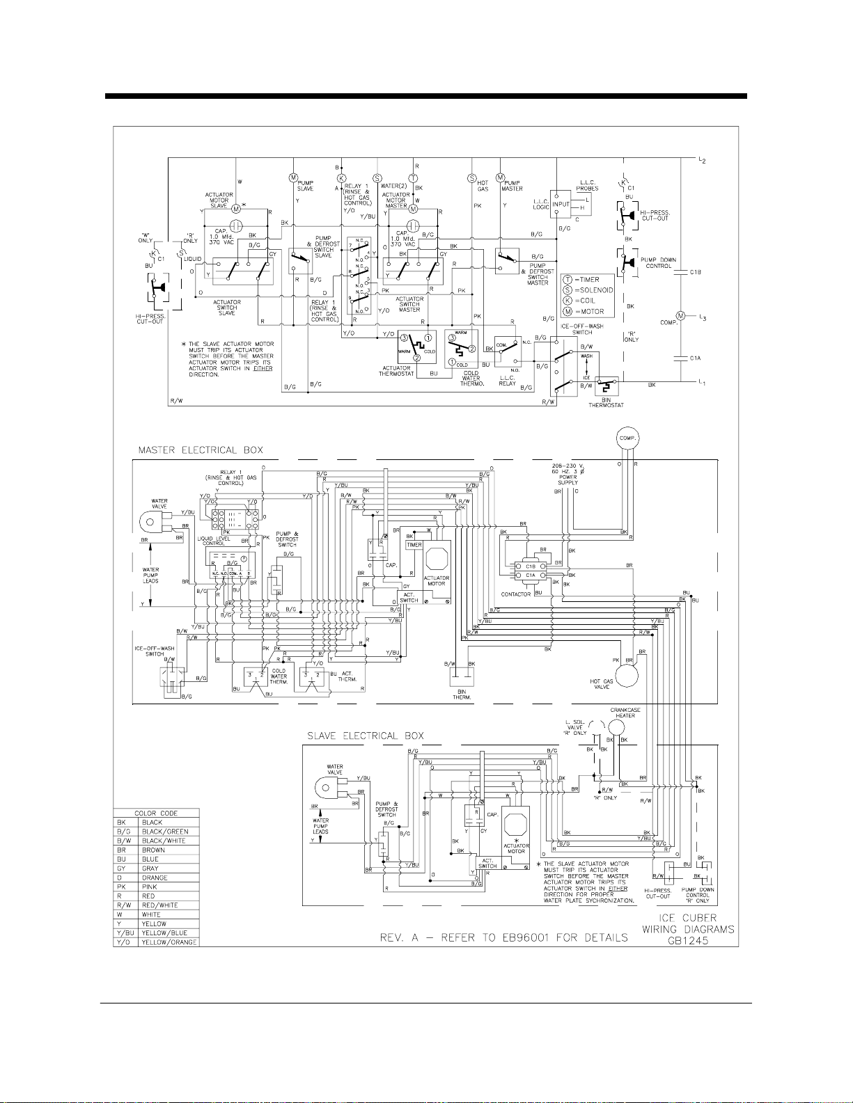
Wiring Diagrams
SEE ENG. BULLETINS #96003, & 97001 FOR WIRING UPGRADES
Kold-Draft® Service & Parts Manual Rev:3/02
-
80 -
Page 82

Wiring Diagrams
SEE ENG. BULLETIN #97001 FOR WIRING UPGRADE
Rev:3/02 Kold-Draft® Service & Parts Manual
- 81 -
Page 83

Wiring Diagrams
SEE ENG. BULLETIN #97001 FOR WIRING UPGRADE
Kold-Draft® Service & Parts Manual Rev:3/02
-
82 -
Page 84

Wiring Diagrams
Rev:3/02 Kold-Draft® Service & Parts Manual
- 83 -
Page 85

Wiring Diagrams
Kold-Draft® Service & Parts Manual Rev:3/02
-
84 -
Page 86

Wiring Diagrams
Rev:3/02 Kold-Draft® Service & Parts Manual
- 85 -
Page 87

Kold-Draft® Service & Parts Manual Rev:3/02
Wiring Diagrams
-
86 -
Page 88

Wiring Diagrams
Rev:3/02 Kold-Draft® Service & Parts Manual
- 87 -
Page 89

WiringDiagrams
New 5/16/03
Kold-Draft®Service & Parts Manual Rev:3/02
-
88 -
Page 90

Wiring Diagrams
New 5/16/03
Rev:3/02 Kold-Draft®Service & Parts Manual
-89-
Page 91

WiringDiagrams
New 5/16/03
Kold-Draft®Service & Parts Manual Rev:3/02
-
90 -
Page 92

Wiring Diagrams
New 5/16/03
Rev:3/02 Kold-Draft®Service & Parts Manual
-91-
Page 93

WiringDiagrams
New 5/16/03
Kold-Draft®Service & Parts Manual Rev:3/02
-
92 -
Page 94

Wiring Diagrams
Rev:3/02 Kold-Draft®Service & Parts Manual
-93-
Page 95

WiringDiagrams
Kold-Draft®Service & Parts Manual Rev:3/02
-
94 -
Page 96

T-25X/T-26X Crusher Installation Instructions
CHECK FOR FREIGHT DAMAGE BEFORE PROCEEDING: Even though damage to
the carton may not have been evident, check for hidden damage and contact freight
carrier immediately if necessary to file a claim.
THIS EQUIPMENT MUST BE INSTALLED IN COMPLIANCE WITH THE
APPLICABLE FEDERAL, STATE/PROVINCE AND/OR LOCAL PLUMBING,
ELECTRICAL AND HEALTH/SANITATION CODES AND REQUIREMENTS.
CAUTION:
{
RISK OF PERSONAL INJURY, PROPERTY DAMAGE, EQUIPMENT FAILURE
OR FIRE.
{
Refer all maintenance to qualified personnel.
{
Never operate this equipment with covers, panels or other parts removed or not
properly secured.
{
Warn all users to clean up spillage immediately, keep storage bin doors
closed, and report any apparent leakage or unusual sounds to maintenance
personnel.
®
Installation
NOTE: Refer to ice cuber instructions before proceeding.
1. Position the ice storage bin maintaining the minimum clearances specified in the
cuber instructions.
Rev:3/02 Kold-Draft
- 95 -
®
Service & Parts Manual
Page 97

T-25X/T-26X Crusher Installation
2. Level the bin with adjusters on legs, or by shimming if the bin is to sealed to the
floor. If gaps due to shims are greater than 1/8 inch, install a cove molding
around the bin bottom. Seal the bin or molding to the floor with NSF Certified
RTV sealant (Dow-Corning RTV 732 or equal).
3. Install gasketing on top of bin if required. Gasket material must be positioned so
that it extends to the outside edge of the perimeter of the crusher chassis when
the crusher is in place.
4. CAREFULLY lift the crusher out of the carton and place onto the gasketed bin.
Remove the front cover and note the alignment of the mounting holes in the
chassis if mounting means are provided on the bin. Follow the bin installation
instructions for securing the crusher to the bin. (NOTE: The selector knob must
be removed before the front cover can be removed.)
CAUTION:
{
RISK OF PERSONAL INJURY OR EQUIPMENT DAMAGE.
{
Use a suitable lifting means and be careful of sharp edges.
5. Electrical and drain locations are shown below. All dimensions are in inches.
6. If a knockout is not provided, punch an 1-3/32 inch dia. hole in the ice maker
condensing unit pan for the crusher control wiring. (See Illustration "A")
Kold-Draft® Service & Parts Manual Rev:3/02
- 96 -
Page 98

T-25X/T-26X Crusher Installation Instructions
7. Install gasketing on top of crusher. (See Illustration "B")
8. Remove the cuber cabinet panels, lift and position cuber on top of gasketed
crusher and align mounting holes. Install cap screws, lockwashers and nuts.
(See Illustration "C") CAUTION: Support cuber until all fasteners are secured.
9. The crusher is designed to operate in conjunction with one or two Kold-Draft
cubers. Two motor control relay blocks are provided and a relay coil must be
installed for each cuber used. Each relay coil must have a voltage rating
matching the voltage of the ice cuber, regardless of the crusher motor voltage.
The relay
coils are installed through the opening in the control box, by the installer, and are
ordered separately. A third relay is provided for controlling one or two cubers
with the same set of bin thermostats. This relay coil voltage rati ng is matched to
the crusher motor voltage and is provided with the crusher.
10. A dual safety switch system is employed in the crusher design to break the
circuit to the motor. If either the front panel of the crusher or the front panel of the
bottom ice maker is removed, a switch will open the motor circuit. The crusher
safety switch is mounted in the crusher control box. The ice maker safety switch
CAUTION:
{
The safety switches DO NOT de-energize all circuits in the crusher or any
circuits in the ice maker. Before cleaning or servicing this equipment,
disconnect all power supplies.
®
Rev:3/02 Kold-Draft
Service & Parts Manual
- 97 -
®
Page 99

T-25X/T-26X Crusher Installation
must be mounted by the installer. (See Illustration "D") If not provided,
locate and drill two 3/16 inch dia. holes in the ice maker lower front rail. Mount the
safety switch support with the #8-32 screws and nuts provided.
11. Install a grommet in the 1-3/32 inch dia. hole in the ice maker condensing unit
pan. Push the crusher control wire assemblies through the grommet into the ice
maker.
12. Connect the safety switch wires from the crusher to the "Common" and
"Normally Open" terminals of the cuber safety switch. (See Wiring Diagram)
13. Route the crusher control wires along the right side of the partition wall to a 7/8
inch hole located to the right of the contactor. Install a grommet in the hole and
push the wires through.
14. The bin thermostat in the cuber must be disabled and replaced by the two
thermostatic switches in the crusher. (See Wiring Diagram)
15. The crushed ice thermostat (left) cap tube is placed into the straight thermostat
tube holder. Push the cap tube into the flared end until the cap tube is visible at
the straight end. Install the tube holder into the hole in the motor platform directly
behind the crusher motor.
16. The cube ice thermostat (right) cap tube is placed into the bent thermostat tube
holder. Mount the tube holder as shown. (See Illustration "E") Tighten clamp
screws. Adjust thermostats to shut off the cuber approximately 1 minute after ice
contacts the tube holders.
CAUTION:
{
Route bin thermostat cap tubes away from moving parts.
Kold-Draft® Service & Parts Manual Rev:3/02
- 98 -
Page 100

T-25X/T-26X Crusher Installation Specifications
INSTALLATION SPECIFICATIONS
The T-250 and T-264 are wired at the factory for 200-240 volt 50/60 hz. operation.
The T-251 and T-261 are wired for 100-120 volt 50/60 hz. operation.
CAUTION:
{
Risk of property damage, equipment failure or fire. Comply with all installation
specifications for safe operation.
Refer to equipment name plate data for current value and maximum fuse size. This unit
must be provided with a separate, properly protected circuit with no other loads. A
fused disconnect installed adjacent to the crusher is recommended (must be supplied
by installer), and may be required by local codes.
Crushers are intended for indoor use only with permanent connection to a field
electrical supply. All models are intended to be installed only in conjunction with
Kold-Draft® cubers on Kold-Draft® bins.
CRUSHER OPERATION
With the crusher knob in the "CRUSHED" position, ice falling from the cuber will be
directed by the selector plate through the crusher mechanism and deposited into the
left side of the bin.
The crusher motor is powered through a relay which is energized by the red circuit of
the ice maker. The selector knob must be in the "CRUSHED" position to close a switch
and complete the circuit to the motor. Additionally, the front panel safety switches must
be depressed (covers on) for motor operation.
Wi th the crusher knob in the "CUBE" position, ice falling from the cuber will bypass the
crusher mechanism and be dumped into the right side of the bin. The crusher motor will
not be energized.
Rev:3/02 Kold-Draft
- 99 -
®
Service & Parts Manual
 Loading...