

Page 1
KOLD-DRAFT
CLASSIC
GB4
5
7
GB6
5
7
®
KOLD-DRAFT
Ice Machine Products
®
Installation & Operation Instructions
1525 East Lake Road, Erie, PA 16511-1088, U.S.A.
Phone: 814-453-6761
FAX: 814-455-6336
©2004 KDIndustries, Inc., Erie, PA, U.S.A.
Printed in U.S.A. 3/04
508 1013 02 English with SI Units
A Tradition of Excellence In Ice Equipment.
Page 2
INSTALLATION AND OPERATION INSTRUCTIONS
FOR
KOLD-DRAFT
CLASSIC
GB SERIES ICE
CUBERS
®
®
CHECK FOR FREIGHT DAMAGE BE PROCEEDING: Even though damage to the
carton may not have been evident, check for hidden damage and contact freight carrier
immediately if necessary to file a claim.
THIS EQUIPMENT MUST BE INSTALLED IN COMPLIANCE WITH THE
APPLICABLE PLUMBING, ELECTRICAL, HEALTH/SANITATION REQUIREMENTS.
CAUTION:
RISK OF PERSONAL INJURY, PROPERTY DAMAGE, EQUIPMENT
FAILURE, OR FIRE.
Refer all maintenance to qualified personnel.
Never operate this equipment with covers, panels, or other parts removed
or not properly secured.
Warn all users to clean up spillage immediately, keep storage bin doors closed,
and report any apparent leakage or unusual sounds to responsible
maintenance personnel.
INSTALLATION
WARNING:
RISK OF CONTAMINATION OF ICE IN THE BIN.
Provide separate, unconnected, drains for the ice maker and the bin.
Consult local regulations for suitable connections to the building drains.
508101302 Rev: 10-5-98
- 2 -
Page 3
CAUTION:
RISK OF PERSONAL INJURY OR EQUIPMENT DAMAGE.
Use a suitable lifting means and be careful of sharp edges.
1. Remove the cabinet panels.
NOTE: When re-installing the panels, be sure that the screws engage the TOP
panel.
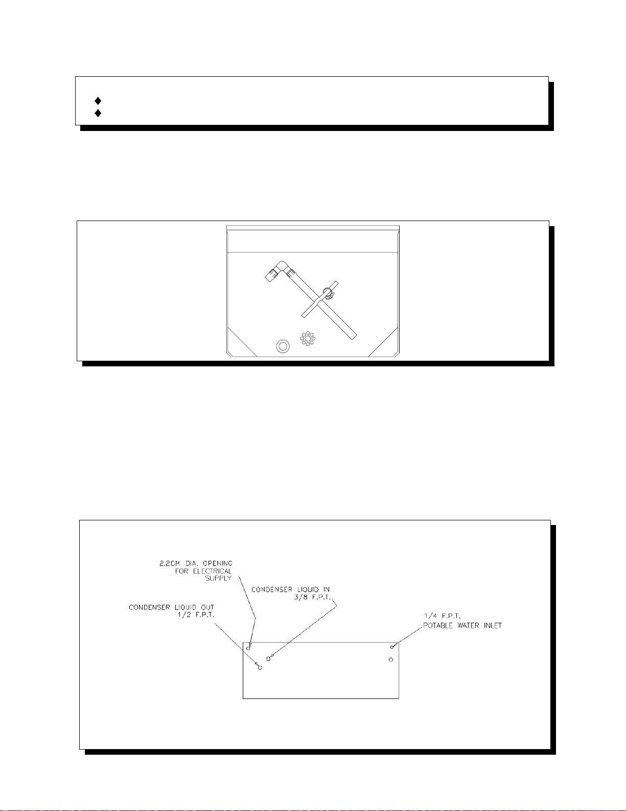
2. Remove the ice deflector, ice chute, and drain pan. Drain tube assembly is
packed with the drain pan as shown below.
3. Install gasketing on top of bin if required.
4. CAREFULLY place the cuber onto the gasketed bin.
5. Install the drain pan, ice chute, and ice deflector. Route the ice maker drain
tube assembly through the rear of the bin, and clamp the tubing to the drain pan
nipple.
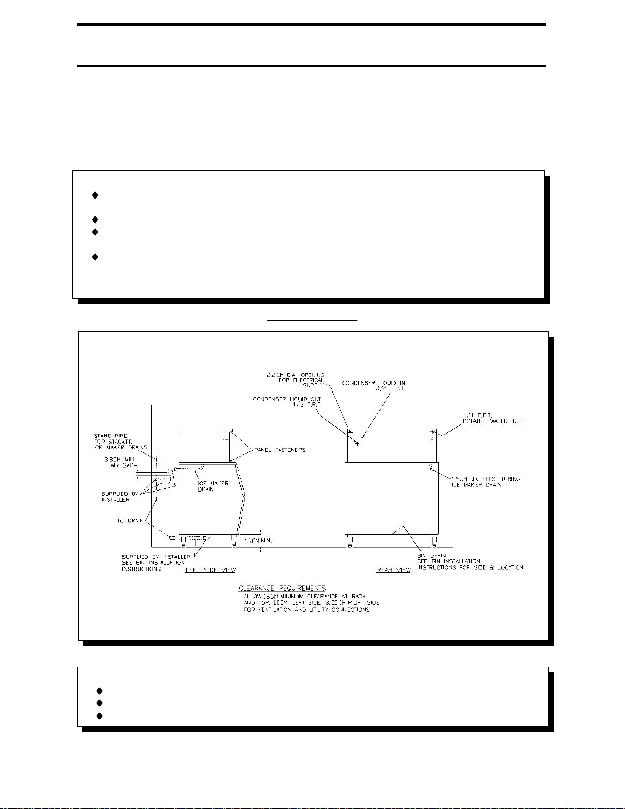
6. Electrical, water and drain locations are shown on the following drawing:
508101302 Rev: 10-5-98
- 3 -
Page 4
7. Purge the potable water supply line.
8. Remove the water plate shipping strap.
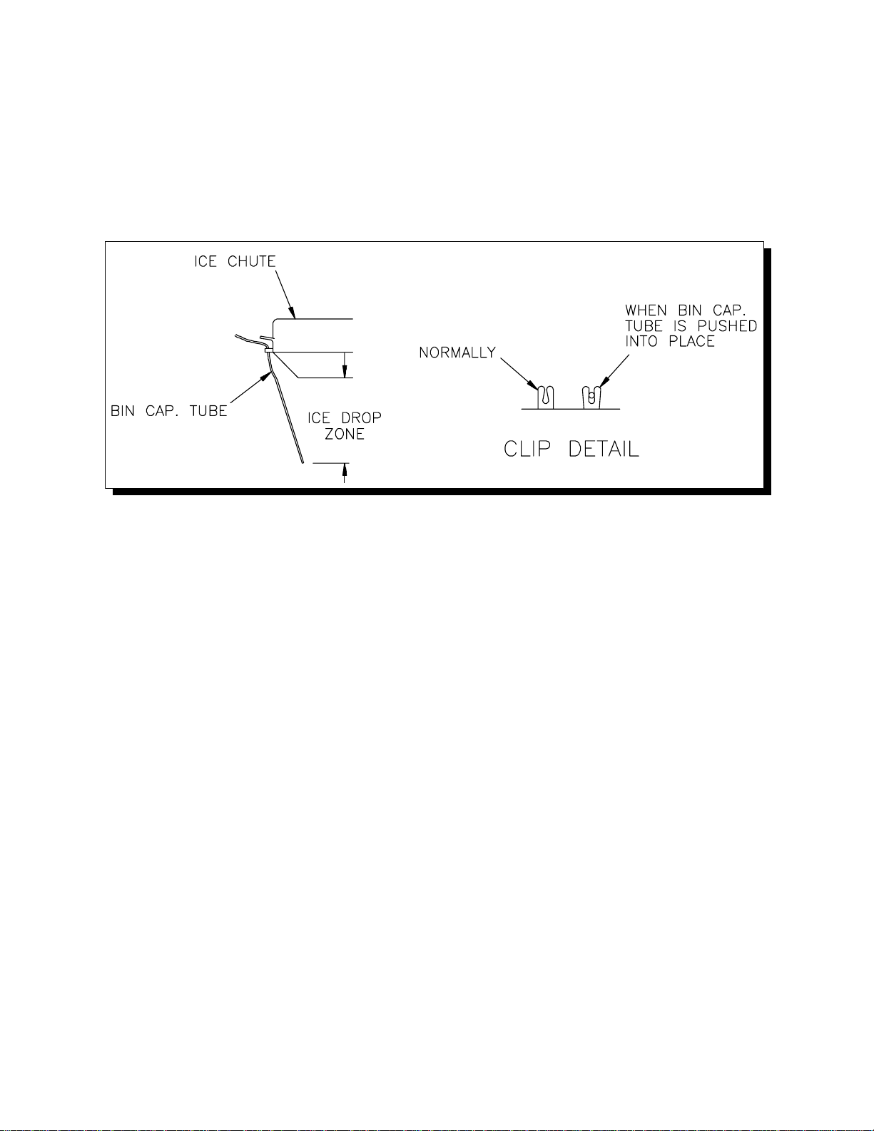
9. Route the bin thermostat capillary tube through the grommet in the compressor
compartment wall and under the ice chute. See the diagram below.
508101302 Rev: 10-5-98
- 4 -
Page 5

INSTALLATION SPECIFICATIONS
READ THE FOLLOWING NOTES CAREFULLY PRIOR TO MAKING CONNECTIONS
CAUTION:
RISK OF PROPERTY DAMAGE, EQUIPMENT FAILURE, OR FIRE.
Failure to comply with all installation specifications and instructions may cause
erratic operation and the risk of damage or fire.
REQUIREMENTS
Electrical:
THE INSTALLER MUST PROVIDE REQUIRED BRANCH CIRCUIT OVERCURRENT
PROTECTION (FUSES) AND DISCONNECTION MEANS.
230 V +/- 10%
50 Hz
GB457: 7,2 A; 1 400 W
GB657: 10,5 A; 2 050 W
Water supply: Minimum 200 kPa supply pressure while the ice maker is filling is
required. Maximum supply pressure is 690 kPa. The water fill flow rate is 3.8 l/min.
Backflow or backsiphonage prevention devices, if required, must be provided by the
installer.
Ice maker drain: Do not reduce the drain tube size.
All models are FOR INDOOR USE ONLY with PERMANENT CONNECTION TO THE
ELECTRICAL SUPPLY (fixed supply wiring connection).
Other operating condition requirements:
Ice maker ambient air temperature: MINIMUM 8°C.; MAXIMUM 30°C.
Climate Class "N" (temperate).
Potable water and condenser liquid supply:
Temperature: MINIMUM 8°C.; MAXIMUM 30°C.
Pressure: MINIMUM 200 kPa; MAXIMUM 690 kPa.*
*If regulator is used, recommended setting is 200 to 345 kPa.
Liquid condenser coolant regulator: The condenser coolant (water) regulating valve
may require adjustment to provide approximately 40o C condensing temperature (1 720
kPa high-side pressure).
508101302 Rev: 10-5-98
- 5 -
Page 6

START-UP INSTRUCTIONS
MODEL NUMBER
WATER LEVELS, CYCLE TIMES, AND REFRIGERANT CHARGES
GB657GB457
Approximate cycle time, min.
Approximate harvest weight, kg.
Refrigerant Charge, grams (R-404a)
850539Air cooled:
652567Liq. cooled:
CAUTION: REFRIGERANT CHARGES MUST BE ACCURATELY WEIGHED.
C/HKKC/HKK
79.279.2Water fill level (Top of tank to level in control tube,cm)
18122819
3.21.83.21.9
1. With the "ICE-OFF-WASH" switch in the center (OFF) position, turn on the
supply water and power.
2. Pour about one liter of potable water into the circulation system to lubricate the
pump seal.
3. Move the "ICE-OFF-WASH" switch to the right (WASH) position and observe
the water fill cycle and the pump running. Water fill is complete when the water
in the liquid level control tube reaches the high-level probe. At this time
observe that the water shuts off and that there are no water leaks.
4. Pull the right end of the water plate down, stretching the springs until the pump
stops, and hold until the pump does not re-start when released. The water plate
will open fully to dump the batch of water, then close immediately. The water
plate should stop when it is fully closed, and the water fill cycle will repeat.
5. After the water fill is complete move the "ICE-OFF-WASH" switch to the left
(ICE) position and observe that the compressor (and fan in "A" models) starts,
and the water pump continues to run.
6. Test the bin thermostat by holding some ice against the capillary tube. If
necessary, adjust the thermostat so that the ice maker stops within 30 seconds
after ice contacts the capillary tube.
508101302 Rev: 10-5-98
7. Be sure that the drain pan, ice chute, and deflector are in place, and that the
electrical control box cover is secured, then replace the cabinet panels. Start
with the SIDE panels, then the FRONT panel. Secure the FRONT panel with
- 6 -
Page 7

(2) screws along the bottom edge, replace the TOP panel, and finally secure all
the panels with (2) screws in the TOP-SIDES of the machine.
8. Discard ice from start-up cycles, then clean and sanitize the bin following the
instructions provided with the bin.
9. Leave this manual with the owner/user. Emphasize the "CAUTION: RISK OF
PERSONAL INJURY..." NOTICE ON THE FIRST PAGE, and the importance of
the PREVENTATIVE MAINTENANCE recommendations below.
PREVENTATIVE MAINTENANCE
CLEANING: 3 to 6 month intervals, depending on water conditions.
INSPECTIONS: During cleaning - at least twice a year.
SERVICE: All such equipment will require service at some time. Service requirements
will be minimized with faithful preventative maintenance including good housekeeping
at the installation site. A CALL FOR SERVICE AS SOON AS A POSSIBLE
PROBLEM IS NOTICED MAY AVOID EXTENSIVE REPAIRS.
508101302 Rev: 10-5-98
- 7 -
Page 8

ICE CUBER CLEANING INSTRUCTIONS
CAUTION:
RISK OF PERSONAL INJURY OR PROPERTY DAMAGE.
Do not use ammonia solutions in cleaning any part of the ice maker.
Do not mix ice machine cleaner and sanitizer together.
Use rubber gloves, eye protection, and an apron.
Clean up splashes or spillage immediately.
Follow these instructions exactly.
1. Mix one bag of KOLD-DRAFT ice machine cleaner (55R-01000) in two (2) liters
of clean, warm water (82oC MAX.).
2. If the cuber is operating, wait until a harvest cycle occurs then trip the
"ICE-OFF-WASH" switch to "WASH" as soon as the water plate begins to close.
3. Empty all ice from the storage bin and shut off other ice makers on the same
bin.
4. After the water fill is completed, switch the "ICE-OFF-WASH" to "OFF". While
pinching water level control hose, carefully remove the water level control tube
from the cap. HOLD THE TUBE HIGH ENOUGH SO THAT THE TUBE DOES
NOT OVERFLOW. Release the hose and pour about half of the mixed cleaner
into the tube. Replace the tube on the cap, while pinching water level control
hose, then pour the remaining cleaner into the control stream box.
5. Switch the "ICE-OFF-WASH" to "WASH" and allow the cleaner to circulate for
approximately 15 minutes, then pull the right side of the water plate down until
the pump stops and hold it until the pump will not re-start when released.
6. The water plate will open and dump the cleaner then close immediately, and the
water system will refill. Repeat this dumping and refilling three (3) times to rinse
out all of the cleaning solution.
7. Mix a sanitizing solution of 60 ml 5-1/4% sodium hypochlorite (household
bleach, or equivalent) and one (1) liter of clean water.
8. As in step #4, pour about half of the sanitizing solution into the water level
control tube and the remaining sanitizer into the control stream box.
9. Allow the sanitizing solution to circulate AT LEAST 15 MINUTES, then dump
and rinse two (2) times as described above. If necessary, reset the water level
probes to the proper levels.
10. While the cleaning and sanitizing solutions are circulating, clean, rinse, and
sanitize all accessible parts of the ice-making compartment of the cuber.
11. After cleaning has been completed, trip the "ICE-OFF-WASH" switch to "ICE"
and check to be sure that the cuber is operating properly, particularly the water
level probes. Then re-assemble and secure all cabinet enclosure panels.
508101302 Rev: 10-5-98
- 8 -
Page 9

ICE BIN CLEANING INSTRUCTIONS
The bin should be cleaned periodically. If bin drain has any horizontal run, remove ice
storage areas.
around the drain fitting and flush with two liters of hot water monthly. (Long drain lines
should be flushed weekly.)
CAUTION:
RISK OF PERSONAL INJURY, EQUIPMENT DAMAGE OR
CONTAMINATION OF THE ICE BIN.
Do not use ammonia solutions or strong detergents in cleaning any part of the
ice maker or bin.
Never use appliance polishers or other finish preservatives or cleaners in ice
1. Clean exterior of bin frequently.
2. To clean the interior, follow instructions provided with bin.
3. Empty the storage area and disconnect the electrical power supply to the ice
maker(s).
4. Remove the ice maker top and front panels, and drain pan. Remove bin doors,
if possible, following the bin instructions.
5. When cleaning the ice maker, follow the ice maker cleaning instructions and
clean the bin last.
6. Replace all enclosure panels before re-connecting the electrical supply.
WINTER CONDITIONING
Ice cubers which are idle in the winter months require preparation as follows to prevent
damage from freezing:
1. Shut off and detach the water supply to the Ice Cuber.
2. Remove all water from the circulation system, solenoid valve, and condenser.
3. Disconnect the electrical supply.
508101302 Rev: 10-5-98
- 9 -
Page 10

508101302 Rev: 10-5-98
- 10 -
Page 11

508101302 Rev: 10-5-98
- 11 -
 Loading...