

Page 1
SEQUENTIAL CIRCUIT DIAGRAM – GB450, GB650 & GT550 MODELS
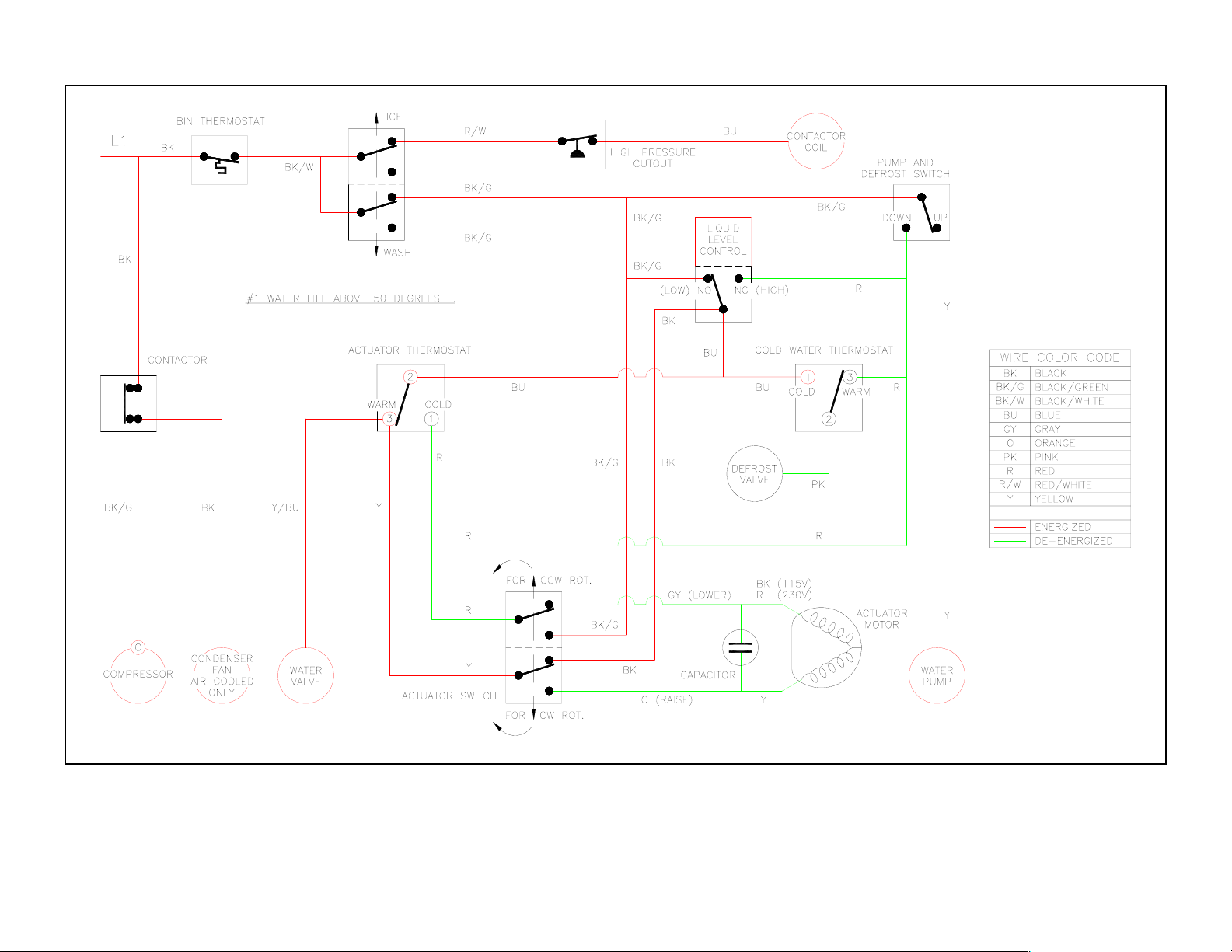
Diagram #1 Water Fill—Evaporator Temperature Above 50°F.
Bin thermostat closed; Switch in “ice” position; Contactor closed; Water plate closed (pump & defrost switch up)
Liquid level control is low, actuator thermostat warm—power to the water valve. Pump and defrost switch up (water plate closed)—power to the
water pump. Cold water thermostat warm.
Page 2
SEQUENTIAL CIRCUIT DIAGRAM – GB450, GB650 & GT550 MODELS
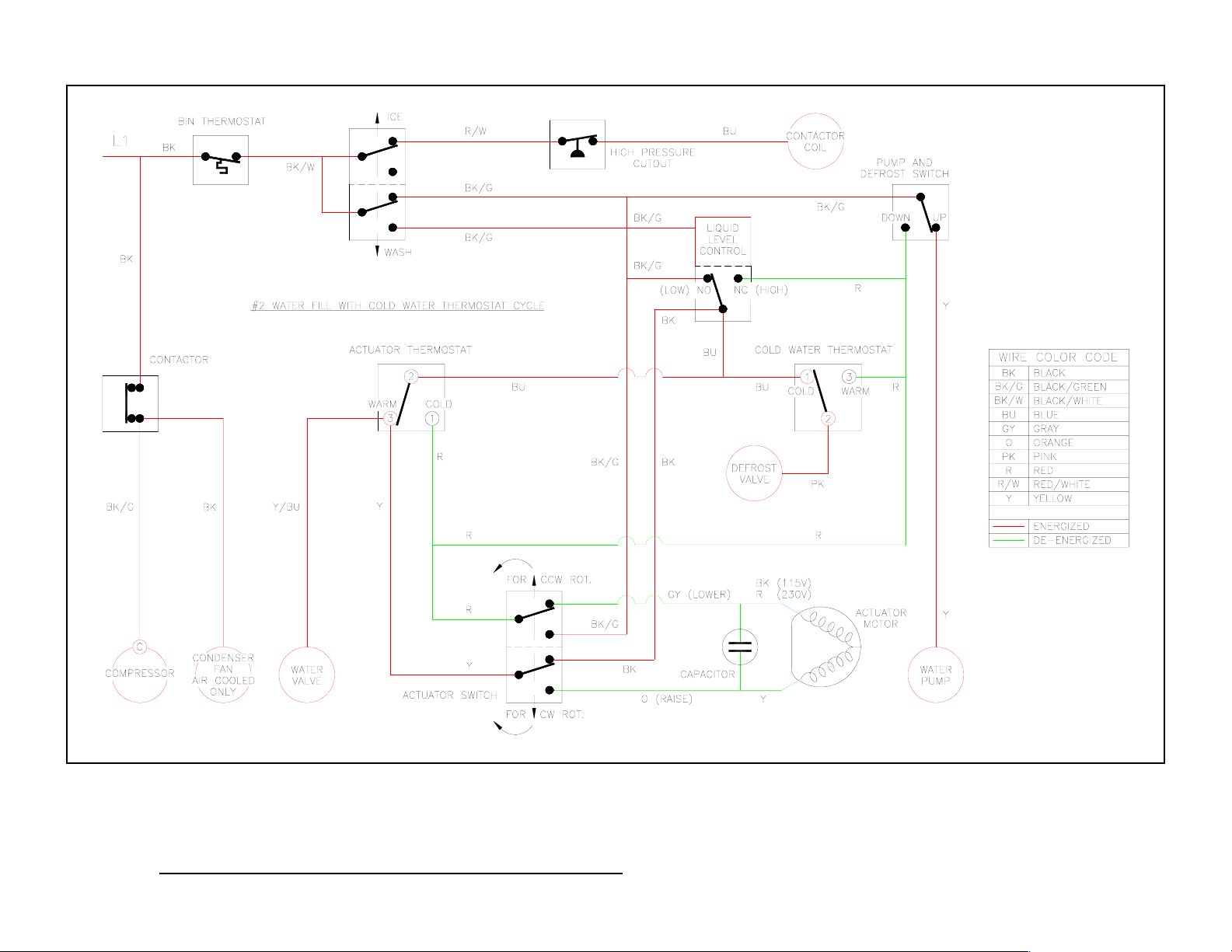
Diagram #2 Water Fill—Cold Water Thermostat Cycle (Evaporator Temperature Below 50°F.)
Bin thermostat closed; Switch in “ice” position; Contactor closed; Water plate closed (pump & defrost switch up)
Liquid level control is low, actuator thermostat warm—power to the water valve. Pump and defrost switch up (water plate closed)—power to the
water pump.
Cold water thermostat switches cold—power to defrost valve.
Page 3
SEQUENTIAL CIRCUIT DIAGRAM – GB450, GB650 & GT550 MODELS
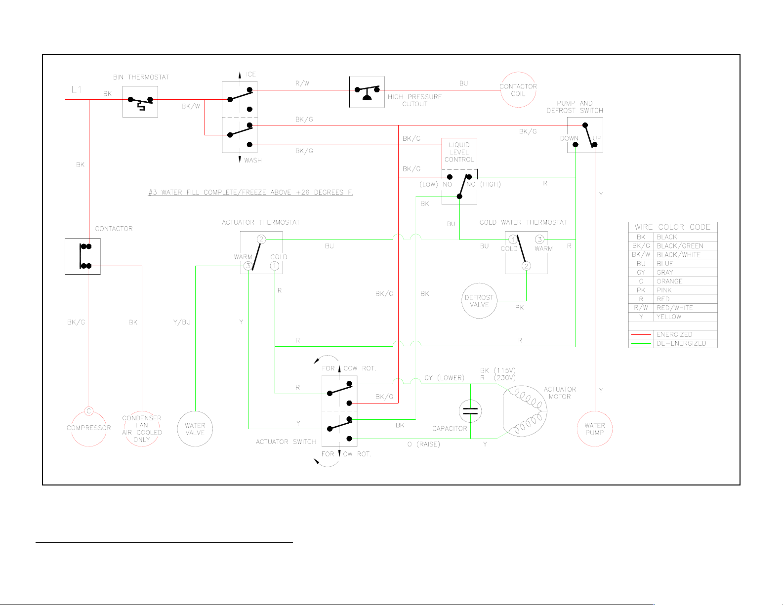
Diagram #3 Water Fill Complete—Evaporator Temperature Above 26°F.)
Bin thermostat closed; Switch in “ice” position; Contactor closed; Water plate closed (pump & defrost switch up)
Liquid level control high—power off to the water valve. Pump and defrost switch up (water plate closed)—power to the water pump. Actuator
thermostat is warm.
Page 4
SEQUENTIAL CIRCUIT DIAGRAM – GB450, GB650 & GT550 MODELS
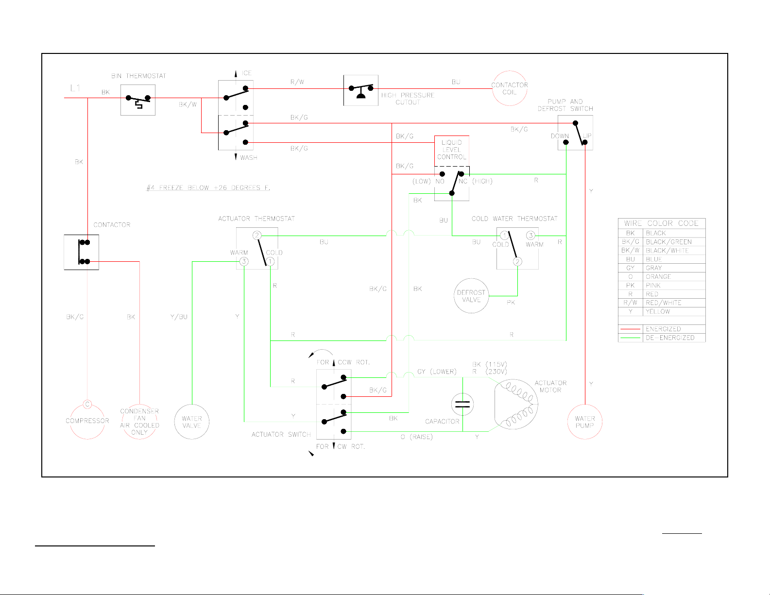
Diagram #4 Ice Forming—Evaporator Temperature Below 26°F.)
Bin thermostat closed; Switch in “ice” position; Contactor closed; Water plate closed (pump & defrost switch up)
Liquid level control high—power off to the water valve. Pump and defrost switch up (water plate closed)—power to the water pump. Actuator
thermostat switches cold.
Page 5

SEQUENTIAL CIRCUIT DIAGRAM – GB450, GB650 & GT550 MODELS
Diagram #5 Defrost- Start of Defrost
Bin thermostat closed; Switch in “ice” position; Contactor closed; Water plate closed (pump & defrost switch up)
Liquid level control switches to low—triggers defrost. Cold water thermostat cold—power to defrost valve. Actuator switch up—power to water
valve. Actuator thermostat cold—power to actuator motor (motor turns CCW). Pump and defrost switch up (water plate closed)—power to water
pump.
Page 6

SEQUENTIAL CIRCUIT DIAGRAM – GB450, GB650 & GT550 MODELS
Diagram #6 Defrost- Water Plate Lowering
Bin thermostat closed; Switch in “ice” position; Contactor closed; Water plate open (pump & defrost switch down)
Liquid level control switch low. Cold water thermostat cold—power to defrost valve. Actuator switch up—power to water valve. Actuator thermostat
cold—power to actuator motor (actuator switch up, motor rotation CCW).
pump.
Pump and defrost switch down (water plate open)—no power to water
Page 7

SEQUENTIAL CIRCUIT DIAGRAM – GB450, GB650 & GT550 MODELS
Diagram #7 Defrost- Water Plate Full Open
Bin thermostat closed; Switch in “ice” position; Contactor closed; Water plate open (pump & defrost switch down)
Liquid level control switch low. Cold water thermostat cold—power to defrost valve. Actuator switch down—power off to actuator motor and water
valve. Actuator thermostat cold. Pump and defrost switch down (water plate open)—no power to water pump.
Page 8

SEQUENTIAL CIRCUIT DIAGRAM – GB450, GB650 & GT550 MODELS
Diagram #8 End of Defrost- Water Plate Closing
Bin thermostat closed; Switch in “ice” position; Contactor closed; Water plate open (pump & defrost switch down)
Liquid level control switch low. Cold water thermostat warm—power to defrost valve. Actuator thermostat switch warm—power to water valve and
actuator motor (actuator switch down, motor rotation CW). Pump and defrost switch down (water plate open)—no power to water pump.
Page 9

SEQUENTIAL CIRCUIT DIAGRAM – GB450, GB650 & GT550 MODELS
Diagram #9 Defrost Ending- Water Plate Almost Closed
Bin thermostat closed; Switch in “ice” position; Contactor closed; Water plate almost closed (pump & defrost switch up)
Liquid level control switch low. Cold water thermostat warm—power to defrost valve. Actuator thermostat switch warm—power to water valve and
actuator motor (actuator switch down, motor rotation CW).
Pump and defrost switch up (water plate almost closed)—power to water pump.
Page 10

SEQUENTIAL CIRCUIT DIAGRAM – GB450, GB650 & GT550 MODELS
Diagram #10 End of Defrost- Water Plate Closed
Bin thermostat closed; Switch in “ice” position; Contactor closed; Water plate closed (pump & defrost switch up)
Liquid level control switch low. Actuator thermostat switch warm—power to water valve. Cold water thermostat warm—no power to defrost valve.
Actuator switch up—power off to actuator motor. Pump and defrost switch up (water plate closed)—power to water pump.
Page 11

SEQUENTIAL CIRCUIT DIAGRAM – GB450, GB650 & GT550 MODELS
Diagram #11 Bin Full- Bin Thermostat Open
Bin thermostat open; Switch in “ice” position; Contactor open; Water plate closed or open
Bin thermostat opens when ice contacts bulb tube—no power to components.
Page 12

SEQUENTIAL CIRCUIT DIAGRAM – GB450, GB650 & GT550 MODELS
Diagram #12 Abnormal Opening of Water Plate
Bin thermostat closed; Switch in “ice” position; Contactor closed; Water plate cannot close (pump & defrost switch down)
Liquid level control switch low. Actuator thermostat switch warm—power to water valve. Cold water thermostat warm—power to defrost valve.
Actuator switch is pushed up—but power is maintained to actuator motor by pump and defrost switch. Pump and defrost switch cannot be pushed
up (water plate obstructed)—red circuit remains energized and water plate re-opens. No power to water pump.
Page 13

SEQUENTIAL CIRCUIT DIAGRAM – GB450, GB650 & GT550 MODELS
Diagram #13 Wash Mode
Bin thermostat closed; Switch in “wash” position; Contactor open; Water plate closed (pump & defrost switch up)
Liquid level control switch high. Actuator thermostat switch warm—power to water valve. Cold water thermostat warm—no power to defrost valve.
Actuator switch up—power off to actuator motor. Pump and defrost switch up (water plate closed)—power to water pump. If liquid level control
switch low, power to water valve.
 Loading...