

Page 1

R
Technical Service and
Replacement Parts Manual
Ice Equipment for 50 Hz. Applications
Models GB457, GB657, GB1257,
GB1258, GT357, and GT557
KDIndustries, Inc.
Erie. PA 16511-1088 U.S.A.
814-453-6761
FAX: 814-455-6336
www.kold-draft.com
LIT 09506 ENG 1-07
1525 East Lake Road
Page 2

THIS PAGE IS INTENTIONALLY BLANK
KOLD-DRAFT®
-
1-07
Page 3
SAFETY WARNINGS AND INFORMATION
KNOWLEDGE OF PROPER INSTALLATION AND SERVICE PROCEDURES IS
ESSENTIAL TO THE SAFE OPERATION AND MAINTENANCE OF KOLD-DRAFT
EQUIPMENT. REFER ALL INSTALLATION AND SERVICE WORK TO QUALIFIED
TECHNICIANS.
ALWAYS DISCONNECT THE POWER SUPPLY BEFORE SERVICING THE EQUIPMENT
OR WHEN THE EQUIPMENT WILL NOT BE USED FOR A PERIOD OF TIME. SOME
CIRCUITS REMAIN ENERGIZED WHEN THE ICE MACHINE IS SWITCHED OFF.
NEVER OPERATE EQUIPMENT THAT HAS BEEN DAMAGED OR DOES NOT HAVE ALL
THE PROTECTIVE COVERS IN PLACE.
NEVER OPERATE EQUIPMENT THAT HAS BEEN ALTERED FROM THE ORIGINAL
KOLD-DRAFT SPECIFICATIONS.
SPECIAL ATTENTION SHOULD BE GIVEN TO POTENTIAL HAZARD LABELING ON
THE EQUIPMENT AND THE SIGNAL WORDS AND SYMBOLS THAT ARE USED
THROUGHOUT THIS MANUAL.
WARNING- Warning is used to indicate the presence of a hazard which can
cause personal injury, death or substantial property or equipment damage, if the
statement is ignored.
CAUTION- Caution is used to indicate the presence of a hazard which can
cause minor personal injury or property damage, if the statement is ignored.
ELECTRICAL CAUTION- Used to indicate the presence of an electrical hazard
which can cause personal injury or property damage, if the statement is
ignored.
NOTE-
which is important, but not a cause of personal injury or property damage.
Note is used to notify personnel of installation, operation or maintenance information
KOLD-DRAFT®
-
1-07
Page 4

Table of Contents
Section 1 General Information
Equipment Identification
Serial Number Plate Location . . . . . . . . . . . . . . . . . . . . . . . . . 1-1
Model Number Key . . . . . . . . . . . . . . . . . . . . . . . . . . . . . 1-2
Date Code Key . . . . . . . . . . . . . . . . . . . . . . . . . . . . . . . . . 1-3
Section 2 Installation Information
Placement . . . . . . . . . . . . . . . . . . . . . . . . . . . . . . . . . . . 2-2
Plumbing . . . . . . . . . . . . . . . . . . . . . . . . . . . . . . . . . . 2-3
Electrical . . . . . . . . . . . . . . . . . . . . . . . . . . . . . . . . . . 2-5
Assembly and Start-Up . . . . . . . . . . . . . . . . . . . . . . . . . . . . . 2-6
Section 3 Operational Information
Components . . . . . . . . . . . . . . . . . . . . . . . . . . . . . . . . 3-1
Controls and Adjustments . . . . . . . . . . . . . . . . . . . . . . . . . . . 3-4
Sequence of Operation . . . . . . . . . . . . . . . . . . . . . . . . . . . . . 3-8
Wiring Diagrams
General Information . . . . . . . . . . . . . . . . . . . . . . . . . . . . . . 3-23
GB457A/W and GB657A/W . . . . . . . . . . . . . . . . . . . . . . . . . . 3-24
GB1257A/W . . . . . . . . . . . . . . . . . . . . . . . . . . . . . . . . . 3-25
GB1258A/W . . . . . . . . . . . . . . . . . . . . . . . . . . . . . . . . . 3-26
GT357A/W . . . . . . . . . . . . . . . . . . . . . . . . . . . . . . . . . 3-27
GT557A/W . . . . . . . . . . . . . . . . . . . . . . . . . . . . . . . . . 3-28
Operational Parameters
Water Fill Levels, Cycle Times and Harvest Weights . . . . . . . . . . . . 3-29
Cube Information . . . . . . . . . . . . . . . . . . . . . . . . . . . . . . . . 3-29
Typical Refrigerant Operating Pressures . . . . . . . . . . . . . . . . . . . 3-29
Refrigerant Charge Information . . . . . . . . . . . . . . . . . . . . . . . . . 3-29
General Information . . . . . . . . . . . . . . . . . . . . . . . . . . . . . . 2-1
KOLD-DRAFT®
-
1-07
Page 5

Table of Contents
Section 4 Service Information
General Information . . . . . . . . . . . . . . . . . . . . . . . . . . . . . . 4-1
Problems and Solutions . . . . . . . . . . . . . . . . . . . . . . . . . 4-3
Test Procedures
Actuator Motor Test Procedure . . . . . . . . . . . . . . . . . . . . . . . . . 4-8
Liquid Level Controller . . . . . . . . . . . . . . . . . . . . . . . . . . . . . 4-9
Compressor Test Procedure . . . . . . . . . . . . . . . . . . . . . . . . . 4-11
Illustrations
Actuator Motor, Switch and Water Plate Spring Relationship . . . . . . . . . 4-15
Water Plate Alignment . . . . . . . . . . . . . . . . . . . . . . . . . 4-16
Web Thickness Adjustment . . . . . . . . . . . . . . . . . . . . . . . . . 4-16
Section 5 Parts
Ice Making Section All GB and GT550 . . . . . . . . . . . . . . . . . . . . 5-2
Water Level Control All GB and GT550 . . . . . . . . . . . . . . . . . . . . 5-3
Water Level Control GT350 . . . . . . . . . . . . . . . . . . . . . . . . 5-4
Ice Making Section GT350 . . . . . . . . . . . . . . . . . . . . . . . . 5-5
GB4(2,3,4,5)7
Chassis Components . . . . . . . . . . . . . . . . . . . . . . . . . 5-6
Control and Electrical Components . . . . . . . . . . . . . . . . . . . . 5-7
Refrigeration Components . . . . . . . . . . . . . . . . . . . . . . . . . 5-8
GB6(2,3,4,5)7
Chassis Components . . . . . . . . . . . . . . . . . . . . . . . . . 5-9
Control and Electrical Components . . . . . . . . . . . . . . . . . . . . 5-10
Refrigeration Components . . . . . . . . . . . . . . . . . . . . . . . . . 5-11
GB12(2,4,5)8
Chassis Components . . . . . . . . . . . . . . . . . . . . . . . . . 5-12
Control and Electrical Components . . . . . . . . . . . . . . . . . . . . 5-13
Refrigeration Components . . . . . . . . . . . . . . . . . . . . . . . . . 5-14
KOLD-DRAFT®
-
1-07
Page 6

Table of Contents
GT3(3,4,5)7
Chassis Components . . . . . . . . . . . . . . . . . . . . . . . . . 5-15
Control and Electrical Components . . . . . . . . . . . . . . . . . . . . 5-16
Refrigeration Components . . . . . . . . . . . . . . . . . . . . . . . . . 5-17
GT557
Chassis Components . . . . . . . . . . . . . . . . . . . . . . . . . 5-18
Control and Electrical Components . . . . . . . . . . . . . . . . . . . . 5-19
Refrigeration Components . . . . . . . . . . . . . . . . . . . . . . . . . 5-20
KOLD-DRAFT®
-
1-07
Page 7
GENERAL INFORMATION EQUIPMENT IDENTIFICATION
WARNING- USE ONLY GENUINE KOLD-DRAFT REPLACEMENT PARTS
USE OF NON-APPROVED PARTS WHEN SERVICING KOLD-DRAFT EQUIPMENT MAY
CREATE A SAFETY HAZARD OR CAUSE EQUIPMENT AND PROPERTY DAMAGE.
USE OF NON-APPROVED PARTS WHEN SERVICING KOLD-DRAFT EQUIPMENT WILL
VOID THE EQUIPMENT WARRANTY.
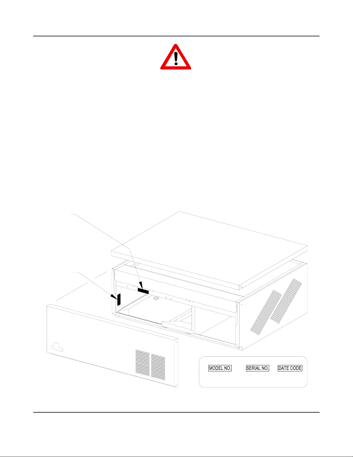
SERIAL NUMBER PLATE LOCATION
NOTE-
A COMPLETE MODEL NUMBER AND DATE CODE ARE ESSENTIAL FOR THE
ACCURATE SELECTION OF REPLACEMENT PARTS.
SEE THE FOLLOWING FOR THE LOCATION OF THE SERIAL NUMBER PLATE.
>1/05
<1/05
KDINDUSTRIES, INC. ERIE, PA. U.S.A.
GB654WK 000000 5EU
208-230V/60HZ/1PH 22oz. R-404a
KOLD-DRAFT®
1-1
1-07
Page 8

GENERAL INFORMATION EQUIPMENT IDENTIFICATION
Classic Model Number Key
GB 4 5 1 W HK
Cube Size
C = Full Cube
HK = Half Cube
K = Cube-Let
Condenser Type
A = Air cooled condenser-self contained
W = Water cooled condenser-self contained
R = Remote air cooled condenser
Electrical Characteristics
1 = 115 volt-60 hz.-1ph. (2-wire plus ground)
4 = 208/230 volt-60 hz.-1ph. (2-wire plus ground)
5 = 208/230 volt-60 hz.-3ph. (3-wire plus ground)
7 = 220/240 volt-50 hz.-1ph. (2-wire plus ground)
8 = 220V/380V-50 hz.-3ph. (4-wire plus ground)
Modification Code
2 = R-502, Copeland compressor except GB1224/25 Bristol
3 = R-502, Bristol compressor
4 = R-404-a, Bristol inertia compressor/POE lubricant except
GT341/GT344 Bristol reed valve compressor/POE lubricant
5 = R-404a, Tecumseh compressor/POE lubricant
Series
3 = 300 Series
4 = 400 Series
5 = 500 Series
6 = 600 Series
12 = 1200 Series
Cabinet Width
GB = 42” Wide
GT = 28-1/2” Wide GT3XX models, 30” Wide GT55X models
KOLD-DRAFT®
1-2
1-07
Page 9
GENERAL INFORMATION EQUIPMENT IDENTIFICATION
DATE CODE KEY
YEAR KEY
4K = 1990 5K = 2000 6K = 2010 7K = 2020
4A = 1991 5A = 2001 6A = 2011 7A = 2021
4B = 1992 5B = 2002 6B = 2012 7B = 2022
4C = 1993 5C = 2003 6C = 2013 7C = 2023
4D = 1994 5D = 2004 6D = 2014 7D = 2024
4E = 1995 5E = 2005 6E = 2015 7E = 2025
4F = 1996 5F = 2006 6F = 2016 7F = 2026
4G = 1997 5G = 2007 6G = 2017 7G = 2027
4H = 1998 5H = 2008 6H = 2018 7H = 2028
4J = 1999 5J = 2009 6J = 2019 7J = 2029
MONTH KEY
M = JANUARY R = APRIL U = JULY X = OCTOBER
N = FEBRUARY S = MAY V = AUGUST Y = NOVEMBER
P = MARCH T = JUNE W = SEPTEMBER Z = DECEMBER
EXAMPLE
4CN = FEBRUARY, 1993 5ET = JUNE, 2005
KOLD-DRAFT®
1-3
1-07
Page 10

THIS PAGE INTENTIONALLY BLANK
KOLD-DRAFT®
1-4
1-07
Page 11
INSTALLATION INFORMATION GENERAL
NOTE!
CHECK FOR FREIGHT DAMAGE BEFORE PROCEEDING WITH THE
EQUIPMENT INSTALLATION. BE SURE TO INSPECT THE EQUIPMENT
CARFULLY FOR ANY DAMAGE THAT MAY NOT HAVE BEEN EVIDENT ON
THE OUTSIDE OF THE CARTON. CONTACT THE FREIGHT CARRIER
IMMEDIATELY TO REPORT ANY DAMAGE AND FILE A CLAIM.
WARNING
DO NOT OPERATE EQUIPMENT THAT HAS BEEN DAMAGED.
REFER ALL MAINTENANCE TO QUALIFIED PERSONNEL.
NEVER OPERATE THE ICE MAKER WITH ANY COVERS, PANELS OR
OTHER PARTS REMOVED OR NOT PROPERLY SECURED.
INSTRUCT ALL PERSONNEL IN THE PROPER USE OF THE EQUIPMENT.
CLEAN UP ANY SPILLAGE IMMEDIATELY.
CAUTION
FAILURE TO COMPLY WITH ALL KOLD-DRAFT INSTALLATION
GUIDELINES MAY CAUSE PERSONAL INJURY, EQUIPMENT OR
PROPERTY DAMAGE AND MAY VOID THE PRODUCT WARRANTY.
KOLD-DRAFT®
2-1
1-07
Page 12

INSTALLATION INFORMATION PLACEMENT
WARNING
ALWAYS INSTALL THE ICE MAKER ON A STABLE AND LEVEL SURFACE.
ALWAYS ATTACH THE ICE MAKER TO THE ICE STORAGE BIN.
ALL MODELS ARE INTENDED FOR INDOOR USE ONLY. DO NOT
INSTALL THE EQUIPMENT IN UNPROTECTED OUTDOOR AREAS.
DO NOT INSTALL THE EQUIPMENT IN WET AREAS.
DO NOT LOCATE THE EQUIPMENT NEAR ANY HEAT SOURCE, IN DIRECT
SUNLIGHT, IN HIGH AMBIENT AREAS, OR WITHOUT PROPER
CLEARANCE FOR VENTILATION. PLACING EQUIPMENT IN THESE
LOCATIONS WILL RESULT IN REDUCED CAPACITIES, HIGH SYSTEM
PRESSURES AND MAY CAUSE EQUIPMENT FAILURE.
AMBIENT OPERATING TEMPERATURES
Minimum 7°C (45°F) Maximum 32°C (90°F)
Ambient temperatures less than 15°C (60°F) may cause erratic bin thermostat operation.
Ambient temperatures higher than the maximum specification will result in reduced capacities
and high system pressures, in air cooled models.
EQUIPMENT CLEARANCE REQUIREMENTS
Clearance must be provided for ventilation and access for service. Ventilation is especially
important for models with air cooled condensers. Failure to provide adequate clearance may
result in reduced capacities and high system pressures. See the installation instructions,
provided with the ice machine, for proper minimum clearance dimensions for a particular
model.
KOLD-DRAFT®
2-2
1-07
Page 13

INSTALLATION INFORMATION PLUMBING
DRAINS
Separate drains must be provided for each ice maker and ice bin. An additional condenser
drain is required for any liquid cooled ice maker, when the condenser coolant will not be recirculated.
The size of the drain tubing must never be reduced along its length.
Make sure that the building drain system can accommodate all the drain water from the ice
machine operation.
Individual drains must never be directly connected to a common manifold, drain or standpipe.
If individual drains are to be discharged into a common manifold, drain or standpipe, a
minimum 38mm (1.5”) air gap must be provided at each connection. This is to prevent any
backflow of drain water into the ice maker or ice bin.
Drain lines must be installed with a minimum drop of 2.5 cm per meter run (.3 inch drop per
foot run).
Ice machine and bin drains may be insulated to prevent condensation.
COOLING TOWER APPLICATION
The ice machine does not need to be modified for use with a cooling tower provided the
cooling tower is properly designed for the application. Information regarding the amount of
heat rejection, as well as the pressure drop through the condenser and liquid valves is
required to properly design a cooling tower application for an ice machine.
Coolant entering the condenser must not exceed 32.2°C (90°F).
Coolant exiting the condenser must not exceed 43.3°C (110°F).
Allow for a pressure drop of 48 kPa (7 psi) between the liquid coolant inlet and outlet of the
condenser.
The condenser liquid control valve will regulate the flow of coolant through the condenser,
thereby controlling the high side pressure in the ice machine.
KOLD-DRAFT®
2-3
1-07
Page 14

INSTALLATION INFORMATION PLUMBING
POTABLE WATER SUPPLY
There are no specific requirements for water treatment provided that the water is potable, not
laden with sediment and does not exhibit a residual chlorine level greater than 0.2 ppm. The
use of water treatment, however, may increase the intervals between cleaning operations.
Do not connect the ice machine to a hot water supply line. Insulate the water line from
sources of heat or to prevent condensation.
NOTE- Purge all water supply lines before connecting them to the ice machine.
CAUTION
HIGH RESIDUAL CHLORINE (MORE THAN 0.2 PPM) CAN CAUSE CORROSION OF ICE
MAKER COMPONENTS AND EVEN THE 300 SERIES STAINLESS STEEL FRAME AND
SKIN PANELS. HIGH CHLORINE LEVELS MUST BE REDUCED, IN THE ICE MAKER
WATER SUPPLY, TO PROTECT THE EQUIPMENT AND PRESERVE THE PRODUCT
WARRANTY.
Please contact your local water conditioning expert for recommendations, about your specific
water supply, or consult the factory.
A minimum 0.2 Mpa (30 psig) dynamic water supply pressure is required for proper operation
of the ice maker water valve. Please note that on liquid cooled ice machines, where the
same water supply is used for both condenser cooling and the potable water supply, the
demand for condenser coolant may cause the supply pressure to drop. This is most notable
at the time of peak load, at the beginning of the freeze cycle.
Minimum water temperature 7°C (45°F) Maximum water temperature 32°C (90°F)
Water temperatures higher than the recommended maximum will cause reduced capacities.
Minimum water pressure 0.2 MPa (30 psig) Maximum water pressure 0.6 MPa (100 psig)
If a water pressure regulator is used, the recommended setting is 0.2 MPa to 0.3 MPa (30 to
50 psig) dynamic.
KOLD-DRAFT®
2-4
1-07
Page 15

INSTALLATION INFORMATION ELECTRICAL
WARNING
ALL KOLD-DRAFT MODELS ARE INTENDED TO BE INSTALLED WITH A
PERMANENT CONNECTION TO THE FIELD ELECTRICAL SUPPLY. DROP
CORD CONNECTIONS SHOULD NEVER BE USED WITH THIS EQUIPMENT.
ALWAYS BE SURE THE POWER SUPPLY IS THE SAME AS THE ICE
MACHINE SPECIFICATION. SEE THE ICE MACHINE ELECRICAL PLATE.
BRANCH CIRCUIT PROTECTION
PROPER PROTECTION MUST BE PROVIDED BY THE USE OF FUSES OR HACR TYPE
CIRCUIT BREAKERS. EACH ICE MAKER MUST BE CONNECTED TO A SEPARATE
PROTECTED CIRCUIT WITH NO OTHER LOADS. A FUSED DISCONNECT, INSTALLED
ADJACENT TO EACH ICE MAKER, IS RECOMMENDED AND MAY BE REQUIRED BY
LOCAL CODES.
Minimum ampacity does not indicate typical running current value. Refer to the equipment
electrical plate. Use the minimum ampacity value for sizing branch circuit conductors up to 8
meters (26 feet) in length. For conductor length over 8 meters, increase the wire gauge as
required.
Normal protector size is based on rated voltage and operation at lower than extreme
temperature limits. Branch circuit conductors may be sized to allow increasing the protector
value up to the specified maximum. This may avoid nuisance protector opening under harsh
operating conditions.
NOMINAL NO-LOAD MAXIMUM FULL-LOAD MINIMUM
220/240 250 210
380 420 360
VOLTAGE TOLERANCE
KOLD-DRAFT®
2-5
1-07
Page 16

INSTALLATION INFORMATION ASSEMBLY AND START-UP
ASSEMBLY
Remove the ice machine top-cover panel, front-cover panel and side-cover panels from the
ice machine frame.
The ice storage bin surface must be level. Use the ice storage bin leg adjusters, if they are
provided. If the bin will be mounted directly to the floor, use shims as required. Seal the bin
to the floor using a sealant with a National Sanitation Foundation certification. If there are
gaps larger than 3 mm install a cove molding around the bottom of the bin.
If not provided, a hole must be installed in the bin top corresponding to the ice drop zone.
Holes are provided in the ice machine frame for the purpose of attaching the ice machine to
the ice storage bin. Use the fasteners provided or other suitable non-corroding fasteners for
this purpose.
Apply gasket material to the ice storage bin top. The gasket material must be positioned at
the outside edge of the ice machine frame.
Carefully lift the ice machine and position it on the ice storage bin. Attach the ice machine to
the ice storage bin.
Make all plumbing and electrical connections to the ice machine and ice storage bin.
Remove all shipping materials from the ice machine including the water plate shipping strap.
Install the bin thermostat capillary tube, into the ice storage bin, according to the instructions
provided with the ice machine.
NOTE- Place the bin thermostat cap tube below any ice deflectors in the storage bin. If
ice piles up, above these deflectors, it may bridge over and not feed down to the lower
section of the bin.
START-UP
Be sure that the ice-off-wash switch is in the “off” (center) position.
Turn on the water supply and the electrical power and check all supply lines for leaks.
Make sure all pump and water tank hoses are connected, then pour .5 liter of clean potable
water into the circulation system to lubricate the pump seal.
KOLD-DRAFT®
2-6
1-07
Page 17

INSTALLATION INFORMATION ASSEMBLY AND START-UP
Move the ice-off-wash switch to the “wash” (right) position and observe the water filling the
water tank and the pump running. Pinch the flexible hose, which connects the water valve to
the water distributor tube, if the distributor tube holes do not produce full streams and it
appears and sounds like air is flowing through the tube. The water fill is complete when the
water level in the probe tube reaches the high-level probe. Observe that the water valve is
de-energized, at this time and there are no water leaks from the hoses or water tank into the
drain pan.
NOTE- For GB1220, 1240, and 1250 models observe that the water fill difference,
between the upper and lower water tanks, is less than 6 mm for “K” models and 3 mm
for “C” and “HK” models.
Pull down on the right side of the water plate, stretching the springs until the water pump
stops and the actuator motor rotates the cam arms counter-clockwise. Allow the cam arms to
rotate far enough so that the pump does not restart when the water plate is released.
Observe that the cam arms continue to turn, opening the water plate fully, dumping the water
in the tank. At this point, the cam arm rotation will reverse and close the water plate. The
cam arm rotation will stop when the water plate is fully closed and the water fill process will
repeat.
Move the ice-off-wash switch to the “ice” (left) position and observe that the compressor and
the fan motor (air cooled only) begin to run. The refrigeration system operation should be
checked and adjusted during the first few cycles. Consult the “OPERATION” section of this
manual for the proper adjustments to the refrigeration system.
Test the bin thermostat operation by holding ice against it. Adjust the thermostat, if required,
to shut off the ice machine within 30 seconds of contact between the ice and the thermostat
capillary tube.
Make sure that the drain pan, ice chute and/or ice deflectors are properly installed. Replace
and secure all the cabinet panels.
Discard all the ice from the start-up cycles, then clean and sanitize the ice storage bin
according to the instructions provided with the bin.
Complete and mail the registration certificate to the factory. Leave all instructions with the
owner/user.
NOTE- Emphasize all cautionary information to prevent personal injury, property
and/or equipment damage.
KOLD-DRAFT®
2-7
1-07
Page 18

THIS PAGE IS INTENTIONALLY BLANK
KOLD-DRAFT®
2-8
1-07
Page 19

OPERATIONAL INFORMATION COMPONENTS
Note: See the Remote Air-Cooled Condenser section of the manual for additional
components related to these ice machines.
REFRIGERANT COMPRESSOR: Provided to pump refrigerant through the refrigeration
system. See the serial number plate for refrigerant specification and electrical
characteristics.
CONDENSER: All air-cooled and liquid-cooled models are provided with a self-contained
refrigerant condenser to remove heat from the refrigeration system. These condensers are
designated in the model number as (“A”) air-cooled and (“W”) liquid-cooled. Remote aircooled condensers are also available for some models. These are designated as (“R”) in the
model number. (See the remote air-cooled section of the manual for information on these
models.)
CONDENSER FAN AND MOTOR: Provided with all air-cooled (“A”) models to draw air
through the condenser.
CONDENSER COOLANT REGULATOR VALVE: Provided with all water-cooled (“W”)
models to regulate the flow of coolant through the condenser and maintain a specified
refrigerant discharge pressure.
RECEIVER: Provided on liquid-cooled and remote air-cooled condenser models for storage
of liquid refrigerant, as required during the operation of the ice machine.
HEAT EXCHANGER: Provided to sub-cool the refrigerant, ensuring that this refrigerant is
liquid at the inlet of the expansion valve.
FILTER DRIER: Provided as insurance that all moisture and impurities are removed from the
refrigeration system.
THERMOSTATIC EXPANSION VALVE: Maintains the proper flow of refrigerant, through the
system, as the load changes during the ice making cycle.
KOLD-DRAFT®
3-1
1-07
Page 20

OPERATIONAL INFORMATION COMPONENTS
EVAPORATOR: A plated copper evaporator is found in all models. The evaporator provides
the five freezing surfaces for ice cube formation.
There are three different evaporators available for Kold-Draft models, depending on the ice
size desired. These evaporators are designated in the model number as (“C”) full cube,
(“HK”) half cube and (“K”) cube-let.
DEFROST VALVE: Directs compressor discharge gas to the evaporator, causing it to warm
and release the ice cubes during the harvest cycle.
STRAINER-WATER INLET: Protects the water valve from particles in the water supply. This
strainer can be cleaned without disconnecting any tubing. If the need for cleaning is frequent,
an external water filter should be provided.
WATER TANK: Provided as a sump to hold the amount of water required to make one batch
of ice cubes.
WATER SOLENOID VALVE: Opens to allow potable water to enter the ice machine and
closes when the water tank is filled to the correct level.
WATER PLATE: Functions as a water manifold with a flat surface. This surface is positioned
close to the evaporator and acts to form the sixth side of the ice cubes. The water plate
surface has one spray hole for each cell in the evaporator, to provide water to the freezing
surfaces. The water plate surface also has two drain holes under each cell, to allow
unfrozen water to return to the water tank to be re-circulated. The water plate swings down
during the harvest cycle to allow the ice cubes to fall out of the evaporator.
There are two different water plate configurations available for Kold-Draft models, depending
on the ice size desired. One is used for (‘C”) full cube models and the other is used for (“HK”)
half cube and (“K”) cube-let models.
WATER PUMP: Continuously circulates the water from the water tank, through the water
plate during the ice making cycle. The water pump also operates during the wash cycle to
circulate cleaning solution.
ACTUATOR MOTOR: Rotates counter-clockwise, at the beginning of the ice harvest cycle,
to lower the water plate, so the ice can fall out of the evaporator. It then rotates clockwise, at
the end of the harvest cycle, to close the water plate for the next ice making cycle.
KOLD-DRAFT®
3-2
1-07
Page 21

OPERATIONAL INFORMATION COMPONENTS
CAPACITOR-ACTUATOR MOTOR: Installed between the two actuator motor windings, the
function of this capacitor is to determine the direction of the rotation of the actuator motor.
CAM ARMS: These are attached to the actuator motor output shaft and function initially to
separate the water plate from the evaporator and then to support the water plate as it opens
fully.
SPRINGS-WATER PLATE: Function as the connection between the cam arms and the
water plate. They also act as a safety mechanism, stretching if any ice remains on the water
plate surface as it is closing against the evaporator.
Additional Component for GB1250 Series Ice Machines
CHECK VALVE-DEFROST: Installed in the defrost tubing to the master (upper) evaporator
to prevent a flow of refrigerant from the master (upper) expansion valve to the slave (lower)
evaporator. This could occur during the ice making portion of the cycle.
KOLD-DRAFT®
3-3
1-07
Page 22

OPERATIONAL INFORMATION CONTROLS AND ADJUSTMENTS
NOTE- See the Remote Air-Cooled Condenser section of the manual for additional
controls, adjustments and considerations related to these ice machines.
BIN THERMOSTAT: Provides power to the ice-off-wash switch. This thermostat functions to
shut off the ice machine, when the ice bin is full. Contact between the ice and the thermostat
capillary tube will cause the thermostat switch to open.
ADJUSTMENT: While holding ice against the thermostat capillary tube, adjust the
thermostat to shut off the ice machine within one minute. A warmer (CCW) adjustment
will shut off the ice machine sooner. A colder (CW) adjustment will delay shut off.
ICE-OFF-WASH SWITCH: Controls the mode of operation of the ice machine.
The “Ice” position provides power to all control circuits including the contactor. (The
contactor provides power to the compressor and also the condenser fan motor in selfcontained air-cooled ice machines.)
The “Wash” position provides power to all control circuits except the contactor. This position
is useful for cleaning the ice machine and for test procedures where operation of the
compressor is not required or desired.
The “Off” position interrupts power to the control circuits.
Note: See the remote air-cooled condenser section of the manual for additional
considerations for these ice machines.
WARNING
ALL ICE MACHINE CIRCUITS ARE NOT DE-ENERGIZED WHEN THIS SWITCH IS IN THE
“OFF” POSITION. ALWAYS DISCONNECT THE POWER TO THE ICE MACHINE
BEFORE SERVICING.
CONTROL STREAM: This is a small clear box, divided into two sections and located on the
front face of the water plate. Water flowing into the left section of the box is returned to the
water tank and recirculated through the system. Water flowing into the right section of the
box is drained out of the system. The velocity of the stream flowing in the box, during the ice
making cycle, is an indicator of the water pressure inside the water plate. This pressure will
increase as the ice cubes fill out in the evaporator, covering the drain holes provided for each
cell. This pressure increase will cause the stream, normally flowing into the left section of the
box, to flow over the partition and into the right section, draining the system of excess water.
KOLD-DRAFT®
3-4
1-07
Page 23

OPERATIONAL INFORMATION CONTROLS AND ADJUSTMENTS
ADJUSTMENT: The stream of water should be adjusted to fall to the left of the control
stream box partition, during the early portion of the ice making cycle, before the cubes
are full.
LIQUID LEVEL CONTROL: This control mechanism is composed of a clear water level tube,
three stainless steel water level probes and a control board.
The water level tube is mounted in front of the water tank and is connected to it by a hose.
As water fills the tank, the water level is visible in the tube.
The water level probes are positioned in the water level tube. Continuity through the water,
between the common probe and the high level probe, will de-energize the water fill circuit. A
break in continuity between the common probe and the low level probe will initiate the harvest
cycle when the evaporator is cold, or energize the water fill circuit when the evaporator is
warm.
ADJUSTMENT: The common probe should be adjusted all the way down.
The low level probe should be adjusted so the tip is approximately 15 mm from the
bottom of the probe tube.
The high level probe determines how much water is taken into the system at the
beginning of a cycle. It is adjusted as required by the size of the cube (“C”, “HK” or
“K”) and the desired fullness (dimple size) of each cube. Typically all cubes should
have a small dimple at the end of the freeze cycle. Lack of a dimple in the cubes is an
indicator that the water tank level is too high at the start of the cycle.
Note: Making cubes without a dimple will reduce ice machine capacity and may
damage the water plate surface in extreme cases. If the control stream is draining
water for more than 15 seconds, at the end of the ice making cycle, the water level in
the tank is too high. Lower the high level probe slightly until proper operation is
evident.
PUMP AND DEFROST SWITCH: This switch is actuated by the water plate and controls the
operation of the water pump. The pump operates when the water plate is closed and the
switch lever is pushed up. If this switch is not actuated when the water plate closes, because
ice is remaining on the water plate surface, the actuator motor will reverse and reopen the
water plate. This will continue until the surface is clear.
ADJUSTMENT: The switch should be actuated when front cam arm is between the 10
o’clock and 11 o’clock positions. Adjust the actuation point on GT350 series machines
by adjusting the height of the actuation screw on the water plate. All other models
have a tab on the water plate that can be easily adjusted by bending it up or down as
required.
Note: Do not bend the switch lever to make this adjustment.
KOLD-DRAFT®
3-5
1-07
Page 24

OPERATIONAL INFORMATION CONTROLS AND ADJUSTMENTS
ACTUATOR THERMOSTAT: This thermostatic switch senses the temperature of the
evaporator, during the ice making cycle and switches from its warm position to its cold
position at approximately 3.3°C (coldest setting—maximum CW adjustment). No change in
the ice machine operation will be noticed at this time. With this thermostat in its cold position,
the circuitry is set up to start the defrost cycle when the cubes are formed and the system
water level drops below the low level probe. After the ice cubes have fallen out of the
evaporator and the evaporator warms to approximately 10°C, the thermostat returns to its
warm position. This ends the defrost cycle and allows the water plate to close and begin a
new ice making cycle.
ADJUSTMENT: The normal adjustment for this thermostat is fully CW (maximum
cold) position. Adjust the thermostat warmer (CCW) only if the defrost time is
insufficient to drop all the ice from the evaporator, before the water plate begins to
close. The defrost time should be increased no more than is required to insure all the
ice has fallen from the evaporator.
Note: Adjusting the thermostat fully CCW (warm) will lock it in its cold switch contact
position. This will keep the water plate open until the thermostat is adjusted CW.
COLD WATER THERMOSTAT: This thermostatic switch is provided on all models, except
the GT350 series and it senses the temperature of the evaporator. When the evaporator is
cold, it connects the defrost valve to the water fill (blue) circuit. When the evaporator is
warm, it connects the defrost valve to the defrost (red) circuit. The water fill (blue) circuit is
energized from the harvest initiation until the water fill is complete. The defrost (red) circuit is
energized whenever the water plate is not fully closed.
The cold water thermostat also acts to prevent false harvest cycles during the water fill
portion of the cycle. If the incoming water is very cold or filling the system at an abnormally
slow rate, the evaporator could become cold enough to switch the actuator thermostat to its
cold position. If this occurs before the water fill is complete, the ice machine will start a
defrost cycle. The water plate will open, dumping the water in the water tank and closing
again to start a new cycle. The cold water thermostat prevents this by energizing the defrost
valve, providing heat to the evaporator before the actuator thermostat can switch to its cold
position.
ADJUSTMENT: The normal adjustment for this thermostat is fully CW (maximum
cold) position. Adjust the thermostat warmer (CCW) only if ice is remaining on the
surface of the water plate between cycles and not being rinsed off. This condition may
be noticed when the supply water is cold and the water level is adjusted to fully form
the cubes (small or no dimples evident in the ice). Adjusting the water level may
improve this problem.
Note: A degraded water plate surface may also contribute to this problem.
KOLD-DRAFT®
3-6
1-07
Page 25

OPERATIONAL INFORMATION CONTROLS AND ADJUSTMENTS
ACTUATOR TOGGLE SWITCH: This switch acts to limit the travel of the actuator motor in
both directions and sets up the circuitry to run the motor in the proper direction when
energized. This is a two position switch that is operated by the output shaft of the actuator
motor. When the motor shaft rotates clockwise, to raise the water plate, it pushes the switch
lever up to stop the rotation when the front cam arm is in the 12 o’clock position (water plate
fully closed). When the motor rotates counter-clockwise, to lower the water plate, it pushes
the switch lever down to stop the rotation when the cam arm is in the 7 o’clock position (water
plate fully open).
ADJUSTMENT: The switch operator, which is attached to the output shaft of the
actuator motor, can be bent slightly to allow the front cam arm to stop in the proper
positions. Bend this operator only if needed to allow the front cam arm to stop at the
12 o’clock position (water plate closed) and the 7 o’clock position (water plate open).
Note: The front water plate spring must be on the left side of the cam hub when the
water plate is fully closed (cam arm in the 12 o’clock position).
CONTACTOR: Provided with all models to carry the compressor load. On air-cooled
models, the condenser fan motor is also connected to the contactor. The contactor coil is
rated for line voltage and the contacts are rated for definite purpose applications (FLA and
LRA).
HIGH PRESSURE CUTOFF: A manual reset pressure switch is provided, which will open
the circuit to the contactor coil if the discharge pressure should reach 3 mPa (gauge) (435
psig).
ADDITIONAL CONTROLS FOR GB1250 SERIES ICE MACHINES
DELAY TIMER-MASTER ACTUATOR MOTOR: This device is used to delay the master
(upper) actuator motor for two seconds to ensure that the slave (lower) actuator motor will
always run ahead of the master motor. The lower actuator toggle switch must always be
actuated before the upper switch. This is required for reliable water plate synchronization.
RELAY-WATER PLATE SYNCRONIZATION: The purpose of this relay, designated as Relay
#1, is to connect the operation of the slave (lower) actuator motor to the position of the
master (upper) actuator toggle switch. This is required for reliable water plate
synchronization.
KOLD-DRAFT®
3-7
1-07
Page 26
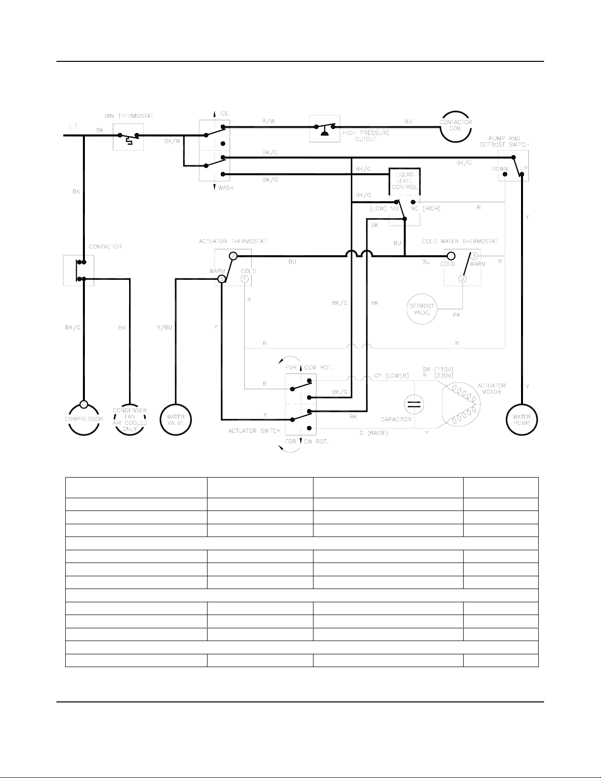
OPERATIONAL INFORMATION SEQUENCE OF OPERATION
THE ELECTRICAL SCHEMATICS ON THE FOLLOWING PAGES DESCRIBE THE
SEQUENCE OF OPERATION OF GB450, GB650 AND GT550 MODELS.
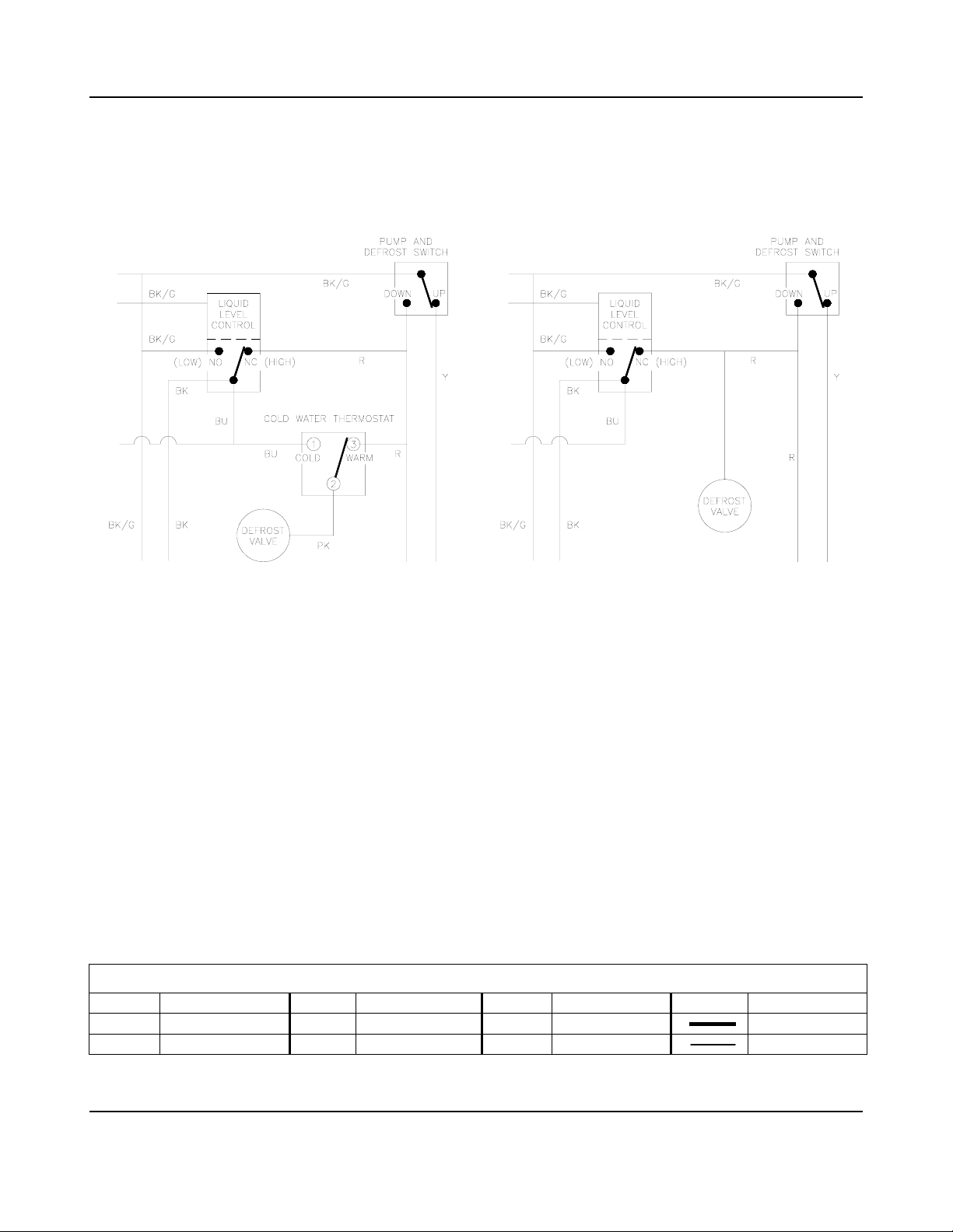
NOTE- The sequence of operation for GT350 models is similar except that these models do
not employ a cold water thermostat. The illustrations below describe this variation.
The sequence of operation for GB1250 models is identical to the GB450, GB650 and GT550
models except additional circuitry is employed to assist in the synchronization of the dual
water plates. This circuitry includes a relay and a delay timer. Also, two additional relays are
used to remove the actuator motor loads from the contacts of the actuator toggle switches.
NOTE- GB1250 models employ two each of the following electrical controls and components:
Condenser Fan Motor (air cooled models only) Water Valve
Water Pump Actuator Motor
Pump and Defrost Switch Actuator Toggle Switch
NOTE- See the Remote Air-Cooled Condenser section of the manual for additional
BK Black BU Blue PK Pink Y Yellow
BK/G Black/Green GY Gray R Red
BK/W Black/White O Orange R/W Red/White
GB450, GB650 AND GT550 GT350 VARIATION
considerations related to the operation of these ice machines.
Wire Color Code for Sequence of Operation Schematics
Energized
De-energized
KOLD-DRAFT®
3-8
1-07
Page 27
OPERATIONAL INFORMATION SEQUENCE OF OPERATION
#1 WATER FILL—EVAPORATOR TEMPERATURE ABOVE 10°C.
Control Status Component Status
Bin Thermostat Warm/Closed
IOF Switch Ice
Contactor Closed Compressor (Condenser Fan) On
Water Plate Closed
Pump and Defrost Switch Up Water Pump On
Cold Water Thermostat Warm Defrost Valve Closed
Actuator Thermostat Warm
Water Level Control Low/Level Rising Water Valve Open
Actuator Toggle Switch Up Actuator Motor Off
Ice None Control Stream Low
KOLD-DRAFT®
3-9
1-07
Page 28
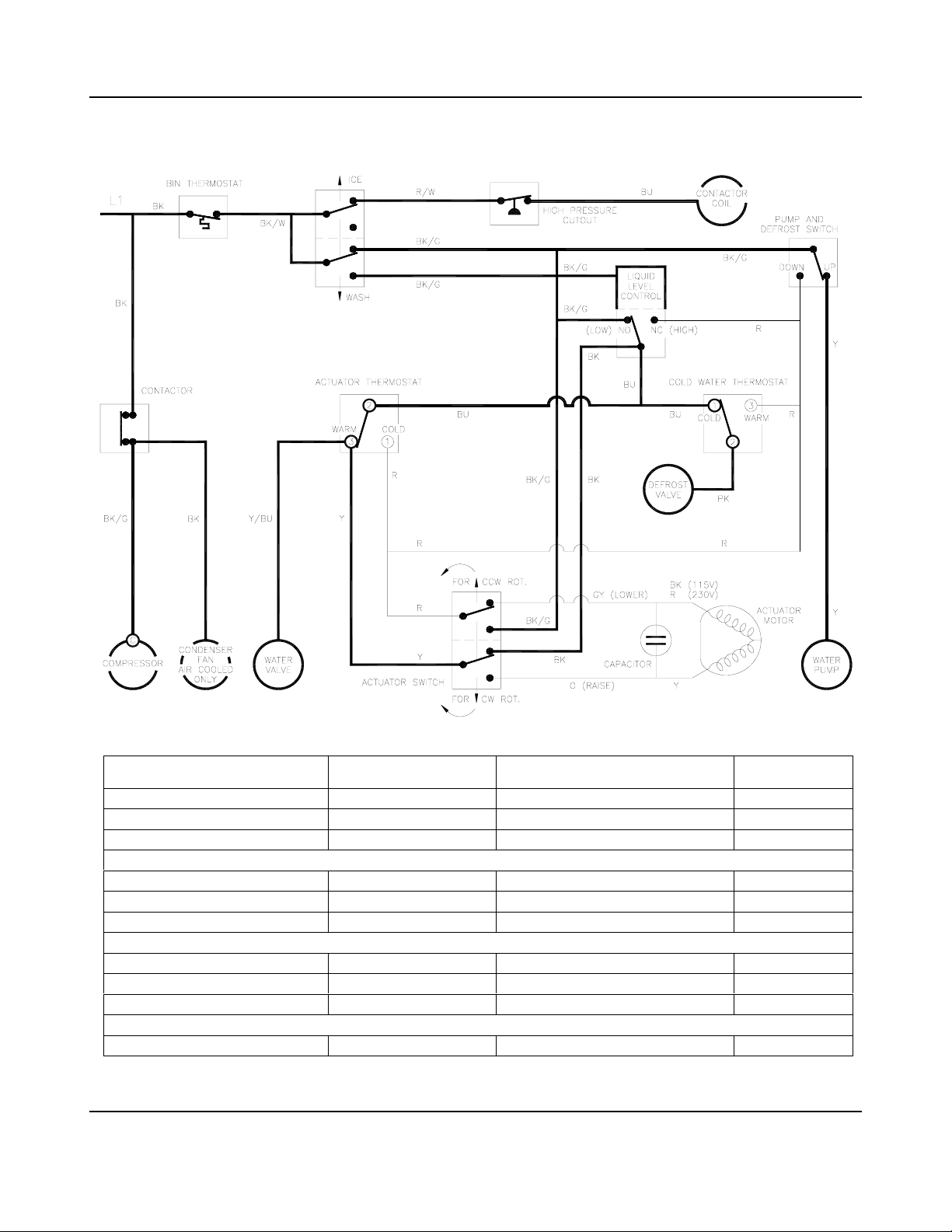
OPERATIONAL INFORMATION SEQUENCE OF OPERATION
#2 WATER FILL WITH COLD WATER THERMOSTAT CYCLE
Control Status Component Status
Bin Thermostat Warm/Closed
IOF Switch Ice
Contactor Closed Compressor (Condenser Fan) On
Water Plate Closed
Pump and Defrost Switch Up Water Pump On
Cold Water Thermostat Cold Defrost Valve Open
Actuator Thermostat Warm
Water Level Control Low/Level Rising Water Valve Open
Actuator Toggle Switch Up Actuator Motor Off
Ice None Control Stream Low
KOLD-DRAFT®
3-10
1-07
Page 29
OPERATIONAL INFORMATION SEQUENCE OF OPERATION
#3
WATER FILL COMPLETE—ICE FORMING—EVAPORATOR TEMPERATURE > 3.3°C.
Control Status Component Status
Bin Thermostat Warm/Closed
IOF Switch Ice
Contactor Closed Compressor (Condenser Fan) On
Water Plate Closed
Pump and Defrost Switch Up Water Pump On
Cold Water Thermostat Cold Defrost Valve Closed
Actuator Thermostat Warm
Water Level Control High/Level Falling Water Valve Closed
Actuator Toggle Switch Up Actuator Motor Off
Ice Forming Control Stream Low
KOLD-DRAFT®
3-11
1-07
Page 30

OPERATIONAL INFORMATION SEQUENCE OF OPERATION
#4 ICE FORMING—EVAPORATOR TEMPERATURE < 3.3°C.
Control Status Component Status
Bin Thermostat Warm/Closed
IOF Switch Ice
Contactor Closed Compressor (Condenser Fan) On
Water Plate Closed
Pump and Defrost Switch Up Water Pump On
Cold Water Thermostat Cold Defrost Valve Closed
Actuator Thermostat Cold
Water Level Control High/Level Falling Water Valve Closed
Actuator Toggle Switch Up Actuator Motor Off
Ice Forming Control Stream Low
KOLD-DRAFT®
3-12
1-07
Page 31

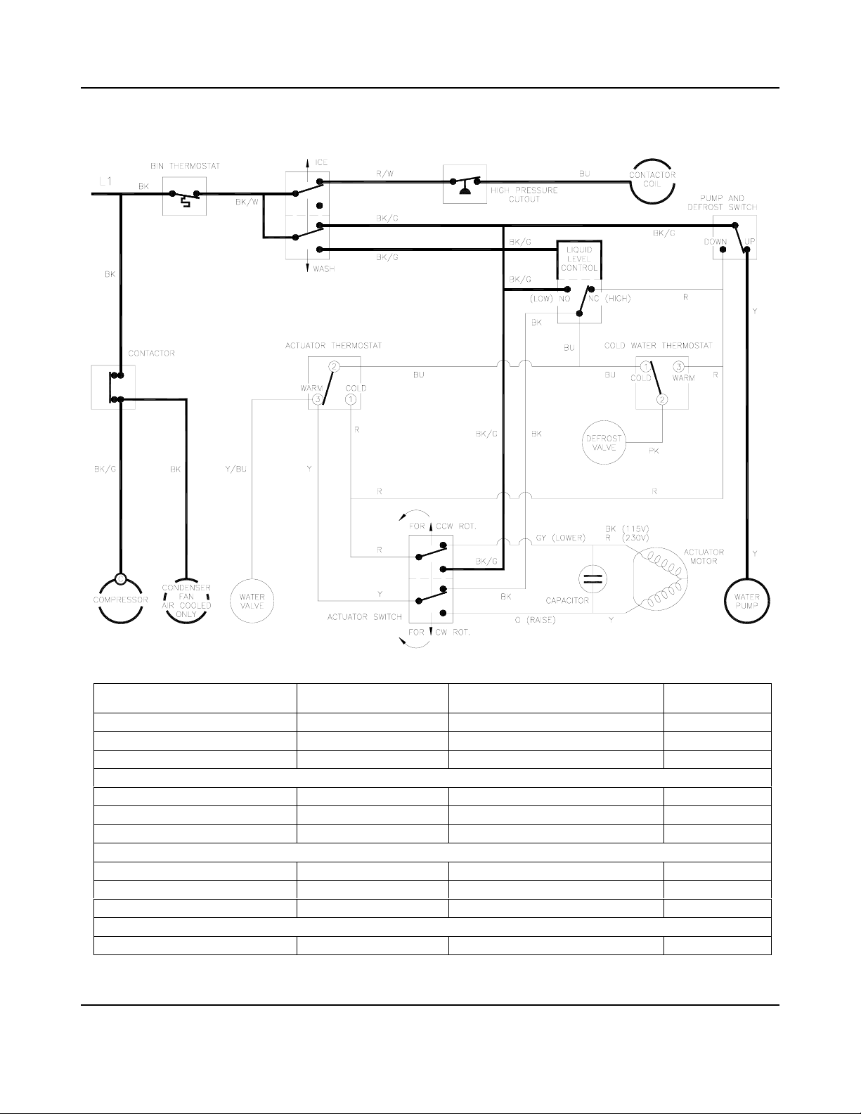
OPERATIONAL INFORMATION SEQUENCE OF OPERATION
#5 DEFROST—START OF DEFROST
Control Status Component Status
Bin Thermostat Warm/Closed
IOF Switch Ice
Contactor Closed Compressor (Condenser Fan) On
Water Plate Starting to Open
Pump and Defrost Switch Up Water Pump On
Cold Water Thermostat Cold Defrost Valve Open
Actuator Thermostat Cold
Water Level Control Low Water Valve Open
Actuator Toggle Switch Up Actuator Motor On/CCW Rotation
Ice Fully Formed Control Stream High If Excess Water
KOLD-DRAFT®
3-13
1-07
Page 32

OPERATIONAL INFORMATION SEQUENCE OF OPERATION
#6 DEFROST—WATER PLATE DROPPING
Control Status Component Status
Bin Thermostat Warm/Closed
IOF Switch Ice
Contactor Closed Compressor (Condenser Fan) On
Water Plate Opening
Pump and Defrost Switch Down Water Pump Off
Cold Water Thermostat Cold Defrost Valve Open
Actuator Thermostat Cold
Water Level Control Low Water Valve Open
Actuator Toggle Switch Up Actuator Motor On/CCW Rotation
Ice Fully Formed Control Stream Off
KOLD-DRAFT®
3-14
1-07
Page 33

OPERATIONAL INFORMATION SEQUENCE OF OPERATION
#7 DEFROST—WATER PLATE OPEN FULLY
Control Status Component Status
Bin Thermostat Warm/Closed
IOF Switch Ice
Contactor Closed Compressor (Condenser Fan) On
Water Plate Open
Pump and Defrost Switch Down Water Pump Off
Cold Water Thermostat Cold Defrost Valve Open
Actuator Thermostat Cold
Water Level Control Low Water Valve Closed
Actuator Toggle Switch Down Actuator Motor Off
Ice Fully Formed Control Stream Off
KOLD-DRAFT®
3-15
1-07
Page 34

OPERATIONAL INFORMATION SEQUENCE OF OPERATION
#8 END OF DEFROST—WATER PLATE STARTS TO CLOSE
Control Status Component Status
Bin Thermostat Warm/Closed
IOF Switch Ice
Contactor Closed Compressor (Condenser Fan) On
Water Plate Starting to Close
Pump and Defrost Switch Down Water Pump Off
Cold Water Thermostat Warm Defrost Valve Open
Actuator Thermostat Warm
Water Level Control Low Water Valve Open
Actuator Toggle Switch Down Actuator Motor On/CW Rotation
Ice None Control Stream Off
KOLD-DRAFT®
3-16
1-07
Page 35

OPERATIONAL INFORMATION SEQUENCE OF OPERATION
#9 END OF DEFROST—WATER PLATE ALMOST CLOSED
Control Status Component Status
Bin Thermostat Warm/Closed
IOF Switch Ice
Contactor Closed Compressor (Condenser Fan) On
Water Plate Almost Closed
Pump and Defrost Switch Up Water Pump On
Cold Water Thermostat Warm Defrost Valve Open
Actuator Thermostat Warm
Water Level Control Low Water Valve Open
Actuator Toggle Switch Down Actuator Motor On/CW Rotation
Ice None Control Stream Off
KOLD-DRAFT®
3-17
1-07
Page 36

OPERATIONAL INFORMATION SEQUENCE OF OPERATION
#10 END OF DEFROST—WATER PLATE CLOSED—START OF NEW CYCLE
Control Status Component Status
Bin Thermostat Warm/Closed
IOF Switch Ice
Contactor Closed Compressor (Condenser Fan) On
Water Plate Closed
Pump and Defrost Switch Up Water Pump On
Cold Water Thermostat Warm Defrost Valve Closed
Actuator Thermostat Warm
Water Level Control Low/Level Rising Water Valve Open
Actuator Toggle Switch Up Actuator Motor Off
Ice None Control Stream Low
KOLD-DRAFT®
3-18
1-07
Page 37

OPERATIONAL INFORMATION SEQUENCE OF OPERATION
#11 ICE BIN FULL—BIN THERMOSTAT OPEN
Control Status Component Status
Bin Thermostat Cold/Open
IOF Switch Ice or Wash
Contactor Open Compressor (Condenser Fan) Off
Water Plate Any Position
Pump and Defrost Switch Up or Down Water Pump Off
Cold Water Thermostat Warm or Cold Defrost Valve Closed
Actuator Thermostat Warm or Cold
Water Level Control High or Low Water Valve Closed
Actuator Toggle Switch Up or Down Actuator Motor Off
Ice None to Fully Formed Control Stream Off
KOLD-DRAFT®
3-19
1-07
Page 38

OPERATIONAL INFORMATION SEQUENCE OF OPERATION
#12 WATER PLATE CLOSING BLOCKED—ICE REMAINS ON SURFACE
Control Status Component Status
Bin Thermostat Warm/Closed
IOF Switch Ice
Contactor Closed Compressor (Condenser Fan) On
Water Plate Closed
Pump and Defrost Switch Down Water Pump Off
Cold Water Thermostat Warm Defrost Valve Open
Actuator Thermostat Warm
Water Level Control Low Water Valve Open
Actuator Toggle Switch Up Actuator Motor On/CCW Rotation
Ice None Control Stream None
KOLD-DRAFT®
3-20
1-07
Page 39

OPERATIONAL INFORMATION SEQUENCE OF OPERATION
#13 HIGH PRESSURE CUT-OUT OPEN
Control Status Component Status
Bin Thermostat Warm/Closed
IOF Switch Ice
Contactor Open Compressor (Condenser Fan) Off
Water Plate Closed
Pump and Defrost Switch Up Water Pump On
Cold Water Thermostat Warm Defrost Valve Closed
Actuator Thermostat Warm
Water Level Control* High Water Valve Closed
Actuator Toggle Switch Up Actuator Motor Off
Ice None Control Stream Low
KOLD-DRAFT®
3-21
1-07
Page 40

OPERATIONAL INFORMATION SEQUENCE OF OPERATION
#14 WASH MODE
*NOTE- The low liquid level control position will open the water valve and fill the water tank.
Control Status Component Status
Bin Thermostat Warm/Closed
IOF Switch Wash
Contactor Open Compressor (Condenser Fan) Off
Water Plate Closed
Pump and Defrost Switch Up Water Pump On
Cold Water Thermostat Warm Defrost Valve Closed
Actuator Thermostat Warm
Water Level Control* High Water Valve Closed
Actuator Toggle Switch Up Actuator Motor Off
Ice None Control Stream Low
KOLD-DRAFT®
3-22
1-07
Page 41

OPERATIONAL INFORMATION WIRING DIAGRAMS
WIRING DIAGRAMS-GENERAL INFORMATION
Wiring Diagram Color Code
BK Black PK Pink
B/G Black/Green R Red
B/W Black/White R/BK Red/Black
BR Brown R/W Red/White
BU Blue W White
GY Gray Y Yellow
O Orange Y/BU Yellow/Blue
O/BK Orange/Black Y/OR Yellow/Orange
FULL RINSE WIRING MODIFICATION
All models may be set up to rinse the water
plate continuously during the defrost cycle.
This is done by moving the Y/BU wire from
terminal 3, on the actuator thermostat, to
terminal 2.
NOTE- This modification will increase
water usage. Make this modification only
if ice remains on the water plate, after
defrost, in sufficient quantities to interfere
with ice cube formation during the following
cycle. Significant Ice remaining on the
water plate is an indication of an im
adjusted ice machine. All possible
adjustments should be tried before ma
this modification. See chapter 4 for oth
adjustments.
NOTE- See the Remote Air-Cooled Condenser section of the manual for wiring
diagrams for these models.
properly
king
er
KOLD-DRAFT®
3-23
1-07
Page 42

OPERATIONAL INFORMATION WIRING DIAGRAMS
GB457A/W AND GB657A/W
KOLD-DRAFT®
3-24A
1-07
Page 43

OPERATIONAL INFORMATION WIRING DIAGRAMS
GB457A/W AND GB657A/W 220-240V/50HZ/1PH
Item Description Item Description
C1 Contactor S1 Ice-Off-Wash Switch
S2 Pump and Defrost Switch
D1 High Pressure Cutout S3 Actuator Switch
D2 Liquid Level Control
T1 Bin Thermostat
T2 Actuator Thermostat
M1 Compressor T3 Cold Water Thermostat
M2 Condenser Fan Motor
M3 Water Pump V1 Hot Gas Valve
M4 Actuator Motor V2 Water Valve
COMPRESSOR WIRING
Item Description Item Description
C1 Contactor SC Start Capacitor
M1 Compressor
RC Run Capacitor SR Start Relay
KOLD-DRAFT®
3-24B
1-07
Page 44

OPERATIONAL INFORMATION WIRING DIAGRAMS
GB1257A/W
KOLD-DRAFT®
3-25A
1-07
Page 45

OPERATIONAL INFORMATION WIRING DIAGRAMS
GB1257A/W 220-240V/50HZ/1PH
Item Description Item Description
C1 Contactor M5 Actuator Motor-Master
M6 Actuator Motor-Slave
D1 High Pressure Cutout
D2 Liquid Level Control S1 Ice-Off-Wash Switch
D3 Delay Timer S2 Pump and Defrost Switch-Upper
S3 Pump and Defrost Switch-Lower
H1 Crankcase Heater S4 Actuator Switch-Master
S5 Actuator Switch-Slave
K1 Relay #1
K3 Relay #3
K4 Relay #4 T1 Bin Thermostat
T2 Actuator Thermostat
M1 Compressor T3 Cold Water Thermostat
M2 Condenser Fan Motor (2)
M3 Water Pump-Upper V1 Hot Gas Valve
M4 Water Pump-Lower V2 Water Valve (2)
COMPRESSOR WIRING
Item Description Item Description
C1 Contactor SC Start Capacitor
M1 Compressor
RC Run Capacitor SR Start Relay
KOLD-DRAFT®
3-25B
1-07
Page 46

OPERATIONAL INFORMATION WIRING DIAGRAMS
GB1258A/W
KOLD-DRAFT®
3-26A
1-07
Page 47

OPERATIONAL INFORMATION WIRING DIAGRAMS
GB1258A/W 380V/50HZ/3PH
Item Description Item Description
C1 Contactor M5 Actuator Motor-Master
M6 Actuator Motor-Slave
D1 High Pressure Cutout
D2 Liquid Level Control S1 Ice-Off-Wash Switch
D3 Delay Timer S2 Pump and Defrost Switch-Upper
S3 Pump and Defrost Switch-Lower
H1 Crankcase Heater S4 Actuator Switch-Master
S5 Actuator Switch-Slave
K1 Relay #1
K3 Relay #3
K4 Relay #4 T1 Bin Thermostat
T2 Actuator Thermostat
M1 Compressor T3 Cold Water Thermostat
M2 Condenser Fan Motor (2)
M3 Water Pump-Upper V1 Hot Gas Valve
M4 Water Pump-Lower V2 Water Valve (2)
KOLD-DRAFT®
3-26B
1-07
Page 48

OPERATIONAL INFORMATION WIRING DIAGRAMS
GT357A/W
KOLD-DRAFT®
3-27A
1-07
Page 49

OPERATIONAL INFORMATION WIRING DIAGRAMS
GT357A/W 220-240V/50HZ/1PH
Item Description Item Description
C1 Contactor S1 Ice-Off-Wash Switch
S2 Pump and Defrost Switch
D1 High Pressure Cutout S3 Actuator Switch
D2 Liquid Level Control
T1 Bin Thermostat
M1 Compressor T2 Actuator Thermostat
M2 Condenser F an Motor
M3 Water Pump V1 Hot Gas Valve
M4 Actuator Motor V2 Water Valve
COMPRESSOR WIRING
Item Description Item Description
C1 Contactor SC Start Capacitor
M1 Compressor
RC Run Capacitor SR Start Relay
KOLD-DRAFT®
3-27B
1-07
Page 50

OPERATIONAL INFORMATION WIRING DIAGRAMS
GT557A/W
KOLD-DRAFT®
3-28A
1-07
Page 51

OPERATIONAL INFORMATION WIRING DIAGRAMS
GT557A/W 220-240V/50HZ/1PH
Item Description Item Description
C1 Contactor S1 Ice-Off-Wash Switch
S2 Pump and Defrost Switch
D1 High Pressure Cutout S3 Actuator Switch
D2 Liquid Level Control
T1 Bin Thermostat
T2 Actuator Thermostat
M1 Compressor T3 Cold Water Thermostat
M2 Condenser Fan Motor
M3 Water Pump V1 Hot Gas Valve
M4 Actuator Motor V2 Water Valve
COMPRESSOR WIRING
Item Description Item Description
C1 Contactor SC Start Capacitor
M1 Compressor
RC Run Capacitor SR Start Relay
KOLD-DRAFT®
3-28B
1-07
Page 52

SERVICE INFORMATION OPERATIONAL PARAMETERS
WATER FILL LEVELS, CYCLE TIMES AND HARVEST WEIGHTS
Model Group and Cube Type
Parameter
Water Fill Level (mm)
(see note)
Approximate Cycle
Time (Minutes)
Approximate Ha rvest
Weight (kg)
Note- Rough measurement from top edge of water tank to water level in control tube after water fill is complete. Additional
fine adjustments may be required.
GB450 GB1250 GT350 GT550
CHKK CHKK CHKK CHKK CHKK
6.99 6.99 9.21 6.99 6.99 9.21 6.99 6.99 9.21 6.67 6.67 7.62 6.99 6.99 9.21
33 26 15 26 21 13 23 18 12 31 21 14 31 24 16
3.49 3.22 1.81 3.49 3.22 1.81 6.99 6.44 3.63 1.77 1.59 0.91 3.49 3.22 1.81
Cube Dimensions (mm) Cube Weight (g)Cube Type
C (Full Cube)
HK (Half Cube) 31 x 31 x 15 15.0 216 216 432 108 216
K (Cube-let) 31 x 15 x 15 8.5 216 216 432 108 216
31 x 31 x 31 32.6
TYPICAL REFRIGERANT OPERATING PRESSURES
Measurement Point
Beginning of Freeze Cycle
Just Before Defrost Cycle Begins
During Defrost Cycle
Note 1- High side pressure in air cooled models, at the beginning of the freeze cycle, is likely to be higher than 1720 kPa.
Note 2- High side pressure in air cooled models, at the end of the freeze cycle, is likely to be lower than 1720 kPa.
Note 3- 1720 kPa is equivalent to 40°C condensing temperature
Low Side (Suction Pressure)
REFRIGERANT CHARGE INFORMATION
Parameter
Refrigerant Charge
GB450 GB650 GB1250 GT350
CHKK CHKK CHKK CHKK CHKK
Refer to Serial Number Plate f or Refrigerant Type and Weight of Charge
GB650
CUBE INFORMATION
345 kPa
80 to 140 kPa
480 to 1030 kPa
Model Group and Ice Size
Cubes per Cycle
GB450 GB650 GB1250 GT350 GT550
108 108 216 54 108
High Side(Discharge Pressure) (R-404a)
Air Cooled
See note 1
See note 2
Approx. 1030 kPa
Liquid Cooled
1720 kPa (See note 3)
1720 kPa (See note 3)
Approx. 1030 kPa
GT550
KOLD-DRAFT®
3-29
1-07
Page 53

SERVICE INFORMATION GENERAL
WARNING
REFER ALL SERVICE WORK TO QUALIFIED TECHNICIANS.
KNOWLEDGE OF PROPER INSTALLATION AND SERVICE PROCEDURES IS
ESSENTIAL TO THE SAFE MAINTENANCE OF KOLD-DRAFT EQUIPMENT.
ALWAYS DISCONNECT THE POWER SUPPLY BEFORE SERVICING THE
EQUIPMENT. SOME CIRCUITS REMAIN ENERGIZED WHEN THE ICE
MACHINE IS SWITCHED OFF.
DO NOT OPERATE EQUIPMENT THAT HAS BEEN DAMAGED.
NEVER OPERATE THE ICE MAKER WITH ANY COVERS, PANELS OR
OTHER PARTS REMOVED OR NOT PROPERLY SECURED.
NEVER MODIFY THE CIRCUITRY OF KOLD-DRAFT EQUIPMENT FROM
THE ORIGINAL SPECIFICATIONS.
USE ONLY GENUINE KOLD-DRAFT REPLACEMENT PARTS.
USE OF NON-APPROVED PARTS WHEN SERVICING KOLD-DRAFT EQUIPMENT MAY
CREATE A SAFETY HAZARD OR CAUSE EQUIPMENT AND PROPERTY DAMAGE.
USE OF NON-APPROVED PARTS, WHEN SERVICING KOLD-DRAFT EQUIPMENT, WILL
VOID THE EQUIPMENT WARRANTY.
KOLD-DRAFT®
4-1
1-07
Page 54

SERVICE INFORMATION GENERAL
NOTE
WHEN SERVICING KOLD-DRAFT ICE MACHINE REFRIGERATION
SYSTEMS, ALL WORK PERFORMED MUST BE CONSISTANT WITH THE
BEST REFRIGERATION SERVICE PRACTICES. THESE SYSTEMS MUST
REMAIN CLEAN, DRY AND PROPERLY CHARGED WITH REFRIGERANT,
IN ORDER FOR THE ICE MACHINE TO OPERATE AS DESIGNED.
CAUTION
FAILURE TO COMPLY WITH ALL KOLD-DRAFT SERVICE GUIDELINES
MAY CAUSE PERSONAL INJURY, EQUIPMENT OR PROPERTY DAMAGE
AND VOIDING OF THE PRODUCT WARRANTY.
NOTE- See the Remote Air-Cooled Condenser section of the manual for additional
service information related to these ice machines.
KOLD-DRAFT®
4-2
1-07
Page 55

SERVICE INFORMATION PROBLEMS AND SOLUTIONS
g
g
y
p
Problem Possible Cause Solution
Ice machine is not operating.
Compressor is not operating.
Water pum p and other
components are operating
normally.
test procedure for more
information.
See compressor
Ice-Off-Wash switch in "off" position
No power at ice machine. Circuit
protector open.
Ice machine off on bin thermostat.
Bin full of ice.
Ice machine off on bin thermostat.
Bin thermostat defective.
Ice machine off on bin thermostat.
Ambient temperature below 10°C.
Ice-Off-Wash switch in "wash"
position.
High pressure cut-out open on air
cooled models. Condenser dirty.
High pressure cut-out open on air
cooled models. Air circulation
through condenser is Insufficient or
hot air is recirculating through the
condenser.
High pressure cut-out open on liquid
cooled models. Coolant liquid
interrupted or insufficient
High pressure cut-out open on liquid
cooled models. Interior of condenser
has a mineral build-up.
High pressure cut-out open.
Refrigeration system is overcharged.
Compressor thermal protector open
because of low voltage condition.
Move swit ch to "Ice" position.
Replace fuse or reset breaker. Check
circuit for overload condition.
Use ice or move ice away from bin
thermostat capillary tube.
Replace bin thermostat.
Ambient temperature must be 15°C
minimum.
Move swit ch to "Ice" position.
Clean condenser and reset high pressure
cut-out. Confirm proper operating
pressures.
Provide adequate spacing between the ice
machine and walls, ceilings or other
equipment. See installation instructions for
spacing requirements. Confirm proper
operatin
Restore adequate coolant liquid supply and
reset high pressure cut out. Confirm proper
operatin
Clean or replace condenser.
System is overcharged with refigerant.
Remove refrigerant and recharge the
s
stem to specifications.
Allow thermal protector to reset. Measure
voltage at contactor while compressor is
running. Correct power supply problem if
voltage is lower than specified on the ice
machine electrical plate.
test procedure for more information.
pressures.
pressures
See compressor
1
Compressor thermal protector open
because of defective run capacitor.
Contactor is defective.
Compressor start capacitor or relay
defective.
Compressor is defective.
Replace run capacitor.
test procedure for more information.
Check for voltage at coil terminals.
Replace contactor if it does not close when
the coil is energized.
Test and replace these parts if defective.
See compressor test procedure for more
information.
Replace compressor. See co mpressor
test
rocedure for more information.
See compressor
KOLD-DRAFT®
4-3
1-07
Page 56

SERVICE INFORMATION PROBLEMS AND SOLUTIONS
Problem Possible Cause Solution
Condenser fan motor is not
operating on air-cooled
models. Compressor is
Fan motor protector open.
Fan motor defective Replace motor.
Condenser sub-cooling >11°C at the
middle point of the freeze cycle on
liquid-cooled models.
Condenser liquid regulating valve not
closing fully during defrost on liquidcooled models.
Replace motor if it does not run when cool
or at normal operating conditions.
System is overcharged with refigerant.
Remove refrigerant and recharge the
system to specifications.
Adjust, repair or replace liquid regulating
valve.
2
Defrost performance slow.
Water plate re-opens
immediately after closing.
Water plate closes but reopens before water fill is
completed.
Air cooled ice machine installed in a
low ambient temperature location.
Ice frozen into the water plate
surface. Thick web between ice
cubes.
Ice frozen into the water plate
surface. Cubes are fully formed
without small dimples.
Ice cubes have large dimples or are
hollow at the end of the freeze cycle.
Batch weight is too light.
Evaporator grids are distorted.
Pump and defrost switch lever is not
being pushed up completely.
Water plate is prevented from closing
by some obstruction such as ice
remaining on the water plate surface.
Water plate springs are stretched or
weak and allow the water plate to
drop slightly as the water fills the
tank. The pump and defrost switch
lever is allowed to drop and re-open
the water plate.
A water plate spring is broken or
disconnected from the cam arm or
the water plate.
Ambient temperature must be 15°C
minimum.
Adjust web thickness to specifications.
Reduce the water fill level until ice cubes
are produced with small dimples.
Increase the water level until ice cubes are
produced with small dimples.
Carefully straighten grids or replace
evaporator if the damage is severe.
Adjust pump and defrost switch ac tuator on
water plate until it pushes up the switch
lever completely.
Eliminate obstruction. Adjust the actuator
thermostat so all ice is out of the evaporator
before the water plate begins to close.
Replace defective springs.
Replace broken spring or reattach
disconnected spring.
KOLD-DRAFT®
4-4
1-07
Page 57

SERVICE INFORMATION PROBLEMS AND SOLUTIONS
Problem Possible Cause Solution
Actuator thermostat will not reset
"warm". Actuator thermostat may be
adjusted fully counter-clockwise
(switch contacts locked in cold
position)
Actuator thermostat will not reset
"warm". Actuator thermostat is
defective or capillary tube is broken.
Adjust actuator thermostat clockwise to
unlock switch c o ntacts.
Replace actuator thermostat.
Water plate will not close after
defrost.
Defrost does not initiate when
water level drops below low
water level probe.
Actuator motor output shaft is tuning
but front cam is not turning.
Actuator motor will not run. No
voltage measured at actuator motor.
Defective actuator switch.
Actuator moto r will not run. Voltage
measured at actuator motor.
Actuator motor or capacitor defective.
Actuator moto r will not run. Voltage
measured at actuator motor.
Actuator motor overheated. Open
thermal overload.
Actuator thermostat will not switch
"cold". Poor contact between the
actuator thermostat capillary tube and
the evaporator.
Actuator thermostat will not switch
"cold". Actuator thermostat is
defective.
Water level control does not switch
when water level is below the low
water level probe.
Cam pin is broken or missing.
Replace actuator switch.
Replace defective actuator motor or
capacitor. See actuator motor t est
procedure for additional informati on.
Let motor cool and determine why motor is
running continuously.
3
Be sure the actuator thermostat capillary
tube is fully inserted into the evaporator
capillary tube holder.
Replace actuator thermostat.
Be sure there is no continuity path between
the probes through water or mineral
deposits on the probe cap. Make sure the
cap is clean and dry especially after
cleaning the ice machine. See water level
control test procedure for additional
information.
Defrost cycle ends and water
plate closes before all ice is out
of the evaporator.
KOLD-DRAFT®
4-5
Actuator thermostat resets "warm"
and terminates defrost too early.
Poor contact between the actuator
thermostat capillary tube and the
evaporator.
Actuator thermostat resets "warm"
and terminates defrost too early.
Improper actuator thermostat
adjustment.
Evaporator grids are distorted.
Be sure the actuator thermostat capillary
tube is fully inserted into the evaporator
capillary tube holder.
Adjust actuator thermostat counterclockwise to a warmer position to extend
defrost time.
Carefully straighten grids or replace
evaporator if the damage is severe.
1-07
Page 58

SERVICE INFORMATION PROBLEMS AND SOLUTIONS
Problem Possible Cause Solution
The water supply pressure must be a
mininmum of 138 kPa dynamic at the water
valve. Be sure that the supply line is of
adequate size. This is especially important
for liquid cooled models where the potable
water and condenser coolant water are
supplied by the same water line. Check for
restrictions in the water supply line including
clogged filters. Check the water line
strainer and clean it if needed.
This is normal operation of the cold water
thermostat. Adjus t the cold water
thermostat fully clockwise to reduce
occurances.
Adjust the cold water thermostat fully
clockwise to reduce occurances.
Adjust web thickness to specifications.
Reduce the water level until ice cubes are
produced with small dimples.
Remove the front cam pin, rotate the cam
180° and replace the pin. Be sure that the
relationship between the front cam, the
actuator motor paddle, the actuator switch
and the water plate spring is correct.
actuator motor paddle, switch and water
plate spring relationship illustration for
more information.
See
4
Defrost valve opens during
water fill.
Ice remains attached to the
water plate surface at the end
of defrost.
Cold water thermostat switches "cold"
because of slow water fill.
Cold water thermostat switches "cold"
because of very cold potable water
supply.
Cold water thermostat switches "cold"
because of improper adjustment.
Ice frozen into the water plate
surface. Thick web between ice
cubes.
Ice frozen into the water plate
surface. Cubes are fully formed
without small dimples.
A full sheet of ice cubes is on the
surface of the water plate as it opens
and the opening of the water plate is
delayed at the start of the defrost
cycle. The front cam is not properly
positioned on the motor shaft.
Water valve will not close.
Potable water level continues
to rise after contacting the tip of
the high water level probe,
during the fill cycle.
water level control test
procedure for additional
information.
KOLD-DRAFT®
4-6
See
No voltage measured at water valve
coil. Water valve remains open
because of water supply problem.
No voltage measured at water valve
coil. Water valve remains open
because of dirty or defective water
valve.
Line voltage measured at water valve
coil. Water valve remains open.
The water supply pressure must be a
mininmum of 138 kPa dynamic at the water
valve. Be sure that the supply line is of
adequate size. This is especially important
for liquid cooled models where the potable
water and condenser coolant water are
supplied by the same water line. Check for
restrictions in the water supply line including
clogged filters. Check the water line
strainer and clean it if needed.
Disassemble and clean water valve if
needed. Make sure the bleed holes in the
valve diaphram are open. Replace or
rebuild water valve if defective.
Test for continuity through the high level
probe. Replace the probe if the continuity is
broken.
1-07
Page 59

SERVICE INFORMATION PROBLEMS AND SOLUTIONS
Problem Possible Cause Solution
Be sure there is no continuity path between
Water valve will not open.
Potable water level never
reaches the high water level
probe, during the fill cycle. See
water level control test
procedure for additional
information.
Poorly formed or cloudy ice
cubes.
Actuator motor turns clockwise
at start of defrost.
No voltage measured at water valve
coil because of an abnormal probe
continuity path.
No voltage measured at water valve
coil because of a defective water
level control.
Water valve closes when water
contacts the tip of the low water level
probe, because the low and high
water level probes are reversed on
the water level control.
Water plate pressure is low. Pump
operating improperly because of low
supply voltage.
Water plate pressure is low.
Improper pump installed in ice
machine.
Water plate pressure is low. Water
plate is cracked or leaking
Ice cubes have large dimples or are
hollow at the end of the freeze cycle.
Water plate is out of alignment with
evaporator.
Ice cubes do not break apart after
defrost because of thick web
between cubes.
Ice cubes have uneven dimples.
Dimples are larger on right side of
evaporator because of low refrigerant
charge.
Ice cubes have uneven dimples.
Dimples are larger on right side of
evaporator because of high
evaporator superheat.
Ice cubes have uneven dimples.
Dimples are larger on left side of
evaporator and ice may freeze into
the right side surface of the water
plate because of low evaporator
superheat.
Actuator motor paddle is not in proper
relationship with actuator toggle
switch.
the probes through water or mineral
deposits on the probe cap. Make sure the
cap is clean and dry especially after
cleaning the ice machine.
Check the water level control output for line
voltage between the COM (common)
terminal and the blue neutral wire. Replace
the control if line voltage is not measured.
Reinstall low and high water level probe
wires on the proper terminals of the water
level control.
Measure the supply voltage with the ice
machine running. Be sure voltage is within
the specified tolerances.
Be sure the pump voltage specification
matches the ice machine voltage
specification.
Repair or replace water plate.
Increase the water level until ice cubes are
produced with small dimples.
Re-align water plate. See water plate
alinment illustration for additional
information
Adjust spacing between evaporator and
water plate.
adjustment illustration for additional
information.
Remove refrigerant and recharge the
system to specifications.
Adjust the expansion valve to decrease the
evaporator superheat.
Adjust the expansion valve to increase the
evaporator superheat.
Re-establish proper relationship between
the actuator motor paddle and the actuator
toggle switch. See actuator motor paddle,
switch and water plate spring
relationship illustration for more
information.
See web thickness
5
KOLD-DRAFT®
4-7
1-07
Page 60

SERVICE INFORMATION TEST PROCEDURES
r
ACTUATOR MOTOR TEST PROCEDURE
The following procedure is used to solve problems with the actuator motor and its related
circuitry. Use a voltmeter set for AC voltage and the proper range. Voltages listed on the
chart are to be measured across the actuator motor capacitor (red and yellow motor lead
wires).
If there is no ice in the evaporator and the water plate is not fully closed—with the water
pump running and the actuator switch tripped up—the actuator motor should be running. If it
is not, be sure there is power to the motor and also that the motor is not overheated and off
due to an open high temperature cut-off. Allow the motor to cool down before starting the
test procedure.
When servicing actuator motor problems in GB1250 models, be sure you understand the
synchronization circuit.
NOTESWhen diagnosing electrical problems, always refer to the proper wiring diagram for the
model you are servicing.
Information in the chart only applies to “new style” actuator motors. These motors
can be identified by the rectangular shaped gearbox and visible motor windings.
Contact the factory for test parameters for “old style” actuator motors.
Actuator Motor Test Parameters
Voltage Reading Capacitor Motor Remedy
290 - 370 Good Good
Line voltage Open Good Replace capacito
Line voltage in one actuator
switch position and 0 volts in
the other position.
290 - 370 volts in one actuator
switch position and 0 volts in
the other position.
0 volts in both actuator switch
positions. Be sure there is
power to the motor (line
voltage) by leaving one probe
on either capacitor lead and
placing the other probe on the
white motor lead.
Open and >
Good
Shorted or >
One motor
winding open
One motor
winding open
Both motor
windings open
Tap gear case to align
bearings
Replace capacitor and motor
Replace motor
Disconnect the actuator motor
from the circuit and test the
winding resistance. If
approximately 400 ohms from
white to red or yellow, replace
the capacitor. If the resistance
is erratic, replace the motor.
KOLD-DRAFT®
4-8
1-07
Page 61

SERVICE INFORMATION TEST PROCEDURES
LIQUID LEVEL CONTROLLER TEST PROCEDURE
The following procedure is used to solve problems with the liquid level control and its related
circuitry. This control senses electrical conductivity, through the water, between its probes.
Even very pure water is somewhat conductive and adjusting the control sensitivity from the
middle range, should not be required.
It is important to note, that this control does not directly energize the water fill valve, while the
actuator thermostat is in the “cold” position. The water plate rinse is powered through the
actuator switch, while the water plate is opening. The rinse water flow stops, when the water
plate is fully open and the actuator switch is pushed down. The water fill for next cycle starts
when the actuator thermostat switches to its “warm” position and the water plate begins to
close.
NOTE- Although the three probe terminals at the top of the control board operate at
low voltage (12 volts AC), all other control board terminals carry line voltage with the
obvious potential for electrical shock. Do not allow the control board to get wet and
use caution when checking voltages.
Before testing the water level control, be sure that there is line voltage at the input terminals.
Also, the Ice-Off-Wash switch should be in the “Wash” position—the water supply must be
turned on—the water plate must be fully closed with the pump and defrost switch lever up—
there must be no ice in the evaporator so the actuator thermostat is in the “warm” position.
The water valve should be energized if none of the water level probes is touching water. If
the valve will not open, measure the voltage at the valve coil. If zero volts, check for possible
conductive path through water or mineral deposits on the probe tube cap. Clean and dry the
cap and measure the valve coil voltage again. If zero volts, check the control output between
the N.O. (normally open) terminal and the brown input wire. Replace the water level control if
line voltage is not measured between these two points.
If the water valve closes when the water level reaches the low level probe, make sure the
high and low level probes are not reversed on the control board terminals. If the probes are
properly attached, replace the water level control.
If the water valve does not close when the water level reaches the high level probe, place the
Ice-Off-Wash switch in the “Off” position. If the water valve remains open, confirm that the
water supply pressure is adequate (138 kPa dynamic at the water valve. Be sure that the
supply line is of adequate size. This is especially important for liquid cooled models where
the potable water and the condenser coolant water are supplied by the same water line.
Check for restrictions in the water supply line, including clogged filters. Check the water line
strainer and clean it, if needed. If the water supply is adequate, clean, repair or replace the
water valve. If cleaning the water valve, make sure that the bleed holes in the diaphragm are
open.
KOLD-DRAFT®
4-9
1-07
Page 62

SERVICE INFORMATION TEST PROCEDURES
If the water valve closes when the Ice-Off-Wash switch is placed in the “Off” position, place
the switch in the “wash” position. Unplug the common probe wire and short between the
common and high probe terminals on the control board. The relay contacts, on the control
board, should open and close when the terminals are shorted and opened. If they do not,
replace the control board.
If the relay appears to be working properly, but the water valve will not close, compare the
control output wire connections (bottom terminals on control board). If the wiring is correct,
replace the control board.
If the probe reaction time is erratic or delayed, clean the probes and/or adjust the sensitivity
dial clockwise.
Note: When replacing the board, be sure the voltage of the new board matches the voltage
specification of the ice machine. Check the label on the control board relay for the correct
operating voltage.
Note: The water fill should be completed within 1.5 minutes for a GB or GT550 “K” model,
2.0 minutes for a GB or GT550 “C” or “HK” model, 1.0 minute for a GT350 “K” model or 1.5
minutes for a GT350 “C” or “HK” model. Long fill times, caused by low dynamic water
pressure supplied to a GB or GT550 ice machine, may cause the cold water thermostat to
switch to the “cold” position, during the water fill cycle. This will open the defrost valve to
warm up the evaporator in order to prevent a false harvest. Cold water thermostat cycles will
reduce the ice making capacity of the ice machine and should be avoided.
ADDITIONAL CONSIDERATION FOR GB1250 MODELS
If there is a fill level difference between the “master” and “slave” water tanks and the
difference is greater than 6 mm for “K” models or 3 mm for “C” or “HK” models, it should be
corrected. If no defect is found in the controller circuit, be sure that the water supply pressure
is adequate (minimum 138 kPa dynamic) and that there are no restrictions in the water lines.
If the fill level difference remains, one of the water valves could defective or a wrong valve
may be installed in the ice machine.
KOLD-DRAFT®
4-10
1-07
Page 63

SERVICE INFORMATION TEST PROCEDURES
COMPRESSOR TEST PROCEDURE
WARNING
DISCONNECT ALL ELECTRICAL POWER BEFORE REMOVING THE PROTECTIVE
TERMINAL COVER.
NEVER ENERGIZE THE SYSTEM UNLESS THE PROTECTIVE TERMINAL COVER IS
SECURELY FASTENED.
NEVER ENERGIZE THE SYSTEM UNLESS THE COMPRESSOR IS PROPERLY
CONNECTED TO GROUND.
NEVER RESET A CIRCUIT BREAKER OR REPLACE A FUSE WITHOUT CHECKING FOR
A SHORT CIRCUIT TO GROUND. AN OPEN FUSE OR TRIPPED CIRCUIT BREAKER IS
AN INDICATION OF A GROUND FAULT. ENERGIZING A COMPRESSOR WITH A
GROUND FAULT MAY CAUSE TERMINAL PIN EJECTION, WHICH WILL ALLOW OIL
AND REFRIGERANT TO SPRAY OUT OF THE SYSTEM. THIS OIL SPRAY, COMBINED
WITH AN ELECTRICAL SPARK, CAN IGNITE CAUSING HARM TO PERSONNEL AND
PROPERTY.
DISCHARGE ALL CAPACITORS WITH A 20,000 OHM RESISTER BEFORE WORKING
WITH THEM OR REMOVING THEM FROM THE ICE MACHINE. THIS MUST BE DONE TO
AVOID DAMAGE TO MEASURING DEVICES AND THE RISK OF ELECTRICAL SHOCK.
NOTE- All Kold-Draft ice machine models utilize CSR (capacitor start/capacitor run)
compressors. Each model includes a potential start relay, a start capacitor and a run
capacitor, in the compressor circuitry, to start and operate these compressors properly and
with maximum efficiency. All compressors also include thermal protectors—external on
GB450, GT350 and GT550 models and internal on GB650 and GB1250 models. This
procedure will help diagnose problems with these compressors and all related components.
If you suspect that there is an electrical problem with a compressor:
1- Test for a short circuit to ground (ground fault).
2- Test the motor windings for proper continuity and resistance.
3- Test the compressor electrical components.
KOLD-DRAFT®
4-11
1-07
Page 64

SERVICE INFORMATION TEST PROCEDURES
1- Test procedure for a short circuit to ground (ground fault):
Disconnect all electrical power to the system, making sure all power legs are open.
Remove the protective terminal cover. Inspect for evidence of overheating at any connection.
Overheating is an indication that a compressor motor problem exists. Disconnect all leads
from the terminal pins.
Check the compressor for a ground fault using an ohm meter or a high potential ground
tester. Connect one lead to the copper suction line and connect the other lead to one of the
terminal pins. Repeat this procedure for the two remaining terminal pins. If the instrument
indicates any resistance less than 2 megohms between any pin and the suction line
(compressor housing), a ground fault exists.
If a ground fault exists, replace the compressor. Do not reconnect the compressor or re-use
any leads or terminal connectors that exhibit signs of overheating.
2- Test procedure for continuity and proper resistance:
If no ground fault has been found, determine if there is an open or short circuited motor
winding or if the thermal protector is open.
Allow time for the thermal protector to reset. This may take as long as an hour for internal
type thermal protectors.
For single phase compressors, test the continuity of the start winding by measuring between
terminal pins C and S. Test the continuity of the main winding by measuring between
terminal pins C and R. If there is no continuity in either winding, replace the compressor.
For three phase compressors, test the continuity of the windings by measuring between each
pair of terminal pins: 1-2, 2-3 and 1-3. If there is no continuity between any set of terminal
pins, replace the compressor.
If continuity is found in all motor windings, measure the resistance (ohms) of the windings.
For single phase compressors, measure between each pair of terminal pins: C-S, C-R and
S-R. The sum of the resistance measured between C-S and C-R should equal the resistance
measured between S-R, plus or minus a small deviation. Proper resistance may be
confirmed by comparing the measured resistance to the resistance specifications for specific
compressor models. If the resistance is not correct, replace the compressor. If the
specifications are not found on the ice machine, please contact the factory.
KOLD-DRAFT®
4-12
1-07
Page 65

SERVICE INFORMATION TEST PROCEDURES
For three phase compressors, measure between each pair of terminal pins: 1-2, 2-3 and 1-3.
The resistance measured between each pair of pins should always be greater than zero and
within 10% of one another. Proper resistance may be confirmed by comparing the measured
resistance to the resistance specifications for specific compressor models. If the resistance
is not correct, replace the compressor. If the specifications are not found on the ice machine,
please contact the factory.
3- Test procedure for compressor electrical components:
TESTING THE POTENTIAL RELAY:
Before testing the relay, be sure it is the one specified for use with the ice machine
compressor and the mounting position of the relay is correct.
Measure for continuity between terminals 5 and 2—if there is no continuity, replace the relay.
Measure for continuity between terminals 2 and 1—if there is no continuity, the contacts are
open and the relay must be replaced.
The relay may also malfunction if the supply voltage is 10% higher or lower than the rated
voltage or if the relay is loosely mounted, allowing it to vibrate or if it is used in conjunction
with an incorrect start capacitor.
TESTING THE RUN CAPACITOR:
Before testing the run capacitor, be sure it is the one specified for use with the ice machine
compressor.
After making sure the capacitor is discharged, disconnect it and test the value with a
capacitance meter. If the measured value is more than 10% higher or lower than the rated
value, replace the run capacitor.
The capacitor may also malfunction if the supply voltage is more than 10% higher than the
rated voltage.
KOLD-DRAFT®
4-13
1-07
Page 66

SERVICE INFORMATION TEST PROCEDURES
TESTING THE START CAPACITOR:
Before testing the start capacitor, be sure it is the one specified for use with the ice machine
compressor.
After making sure the capacitor is discharged, disconnect it and test the value with a
capacitance meter. If the measured value less than the rated value or more than 20% higher
than the rated value, replace the start capacitor.
As an alternative, test the run capacitor by determining if there is continuity across the
terminals. Use a meter set to the R x 1 scale. If there is continuity the capacitor is shorted
and must be replaced.
Another alternative is to set the meter to the R x 100,000 scale. If there is no needle
deflection on an analog meter when placing the probes across the capacitor terminals or if
infinite resistance is indicated on a digital meter, the capacitor is open and needs to be
replaced.
The capacitor may also malfunction if the relay contacts are not working properly, or if the
capacitor is subjected to prolonged operation of the start cycle, because the start relay is
incorrect, the starting load is too high, or the supply voltage is more than 10% lower than the
rated voltage.
TESTING THE EXTERNAL THERMAL PROTECTOR:
After allowing sufficient time for the thermal protector to reset, disconnect it and test for
continuity across the terminals. If there is no continuity, replace the thermal protector.
ADDITIONAL INFORMATION
Disconnect and test the compressor wiring by confirming that there is continuity between
relay terminal 5 and compressor terminal C and also between terminals 2 and S as well as 4
and R.
Replace the potential relay if all other tests do not reveal the problem. A new relay will
eliminate any electrical problems that cannot be determined with the previous testing. If a
new relay does not correct the operation, the compressor may have a mechanical problem.
Note: Excessive short cycling may be caused by a faulty thermal protector, but it also may
be caused by other malfunctioning system components such as the bin thermostat, Ice-OffWash switch, contactor or high pressure cut-out.
KOLD-DRAFT®
4-14
1-07
Page 67

SERVICE INFORMATION ILLUSTRATIONS
ACTUATOR MOTOR PADDLE, SWITCH, CAM ARM AND WATER PLATE SPRING
RELATIONSHIP ILLUSTRATIONS
When the water plate is closed, the cam arm must be in the twelve o’clock position and the
actuator switch lever is up. See illustration “A”. To open the water plate, the motor turns
counter clockwise until the motor paddle pushes the actuator switch lever down. The cam
arm is in the seven o’clock position when the water plate is fully open. See illustration “B”.
When closing the motor turns clockwise, from the seven o’clock position to the twelve o’clock
position. The front spring is on the left side of the front cam hub when the water plate is
closed. See illustration “C”.
NOTE: Component relationships and operation other than described here indicate
actuator switch failure or improper reassembly when servicing the ice machine.
KOLD-DRAFT®
4-15
1-07
Page 68

SERVICE INFORMATION ILLUSTRATIONS
WATER PLATE ALIGNMENT ILLUSTRATION
If the water plate is not aligned with the
evaporator, the cubes may appear
cloudy or misshapen.
Dimension “A” is not adjustable. If this
dimension is out of tolerance, the
evaporator or water plate mounting
components may be damaged.
Adjustments to dimension “B” can be
made by sliding the front and rear
hinges along the left edge of the water
plate. Lightly tap the hinges as required
to align the water plate with the
evaporator. Alignment is correct when
the space between the evaporator and
the water plate is equal in front and in
back.
“A” = 38 +/- 2.5 mm “B” = 8 +/- 1.5 mm
WEB THICKNESS ADJUSTMENT
The web thickness between
cubes (the gap between the
bottom of the evaporator and
the water plate surface) can
be adjusted by inserting or
removing shims between the
support channels and the
evaporator support posts or
the cam shaft bearing
brackets. Loosen the
actuator motor mounting
screws before inserting or
removing shims between the
channels and cam shaft
bearing brackets. The web
thickness specification is as
follows:
“C” and “HK” models = 2.0 mm “K” models = 1.3 mm
KOLD-DRAFT®
4-16
1-07
Page 69

THIS PAGE IS INTENTIONALLY BLANK
KOLD-DRAFT®
5-1
1-07
Page 70

ICE MAKING COMPONENTS-GB & GT550
8 10 11 12 13
9
7
14
6
15
5
4
16
3
17
2
18
1
KOLD-DRAFT®
2
24
5-2A
23
22
19
20
21
1-07
Page 71

ICE MAKING COMPONENTS-GB & GT550
Item Description Number
See Control and
Electrical
1 Water Pump
2 Hose Kit GBR 02087
3 Water Distributor Tube GBR 00403
4 Roll Pin GBR 00959
5 Motor Shaft Extension 102 1209 01
6 Front Cam GBR 00969
7 Front Cam Pin 102 1210 01
8 Cam Shaft GBR 00942
9 Water Strainer GBR 01379
10 Evaporator Shim Set GBR 00111
Components
11
Evaporator Spacer Set "C"/"HK" GBR 00113
Evaporator Spacer Set "K" GBR 00126
12 Cam Shaft Shim Set GBR 00580
13 Rear Cam GBR 00949
14 Spring GBR 00909
15 Cam Shaft Bracket GBR 00937
Evaporator "C" GBR 00148
16
Evaporator "HK" GBR 00167
Evaporator "K" GBR 00153
17 Water Plate Hinge Set GBR 00282 06
18
Water Plate "C" GBR 00200
Water Plate "HK"/"K" GBR 00270
19 Spring Boss GBR 00951
20 Water Deflector GBR 00202
21 Water Plate Plug Set GBR 00223
22 Water Tank GAR 00203
23 Water Tank Screen GBR 00245
24 Probe Tube Assembly 102 1216 01
KOLD-DRAFT®
5-2B
1-07
Page 72

ICE MAKING COMPONENTS-GB & GT550
28
27
24
26
25
Item Description Number
24 Probe Tube Assembly 102 1216 01
25 Probe Tube GBR 03172
26 Probe-Common 102 1281 01
27 Probe-Long 102 1281 01
28 Probe-Short 102 1280 01
KOLD-DRAFT®
5-3
1-07
Page 73

ICE MAKING COMPONENTS-GT350
27
26
23
25
24
Item Description Number
23 Probe Tube Assembly 102 1216 02
24 Probe Tube GBR 03172
25 Probe-Common 102 1281 01
26 Probe-Long 102 1283 01
27 Probe-Short 102 1282 01
KOLD-DRAFT®
5-4
1-07
Page 74

ICE MAKING COMPONENTS-GT350
4
3
2
5
6 810
7
9 11
12
13
14
15
16
1
23
17
18
19
20
2122
KOLD-DRAFT®
5-5A
1-07
Page 75

ICE MAKING COMPONENTS-GT350
Item Description Number
See Control and
Electrical
1 Water Pump
2 Hose Kit GBR 02087
3 Water Distributor Tube 102 1154 02
4 Front Cam GBR 00969
5 Front Cam Pin 102 1210 01
6 Cam Shaft 102 1221 01
7 Water Strainer GBR 01379
8 Evaporator Shim Set GBR 00111
9 Cam Shaft Shim Set GBR 00580
Components
10
Evaporator Spacer Set "C"/"HK" GBR 00113
Evaporator Spacer Set "K" GBR 00126
11 Rear Cam GBR 00949
12 Spring GBR 00909
13 Cam Shaft Bracket-Rear GBR 00937
14 Cam Shaft Bracket-Front 102 1222 01
Evaporator "C" 102 1025 02
15
Evaporator "HK" 102 1025 03
Evaporator "K" 102 1025 04
16 Water Plate Hinge Set GBR 00282 06
17
Water Plate "C" GTR 00221
Water Plate "HK"/"K" GTR 00222
18 Spring Boss GBR 00951
19 Water Deflector GYR 00202
20 Water Plate Plug Set GBR 00223
21 Water Tank GYR 00201
22 Water Tank Screen GYR 00219
23 Probe Tube Assembly 102 1216 02
KOLD-DRAFT®
5-5B
1-07
Page 76

CHASSIS COMPONENTS-GB4(2,3,4,5)0
1
234
10 9 8 7 6 5
KOLD-DRAFT®
5-6A
1-07
Page 77

CHASSIS COMPONENTS-GB4(2,3,4,5)0
Item Description Number
1 Electrical Box Cov er 102 1251 01
2 Left Side Panel 102 1203 01
3 Top Panel 102 1205 01
4 Right Side Panel 102 1204 01
5 Ice Deflector Set 102 1336 01
6 Ice Chute-Plastic GBR 00668
7 Drain Tube 102 1201 01
8 Front Deflector 102 1211 01
9 Drain Pan 102 1100 01
10 Front Panel 102 1202 01
KOLD-DRAFT®
5-6B
1-07
Page 78

CONTROL AND ELECTRICAL COMPONENTS-GB4(2,3,4,5)7
123 4 5 76
8
9
10
11
18 16 15 14 13 12
17
KOLD-DRAFT®
5-7A
1-07
Page 79

CONTROL AND ELECTRICAL COMPONENTS-GB4(2,3,4,5)7
Item Description Model Number
1 Water Valve GBR 01376 FF
2 Liquid Level Control 102 1142 01
3 Pump and Defrost Switch 102 1217 01
Actuator Motor Capacitor-1.0 mF (New Style Motor) 102 1241 02
4
Actuator Motor Capacitor-1.5 mF (Old Style Motor) GBR 00826
5 Actuator Motor 102 1292 02
6 Contactor-Single Pole 102 1036 01
GB427 N/A
7 Run Capacitor
GB437 102 1197 04
GB447 102 1197 01
GB457 102 1044 01
GB427 102 1194 01
8 Start Relay
GB437 102 1047 03
GB447 102 1047 07
GB457 102 1047 11
High Pressure Cut Off-Manual reset 102 1055 01
9
High Pressure Cut Off-Automatic reset GBR 02354
10 Defrost Valve Coil 102 1012 01
11 Defrost Valve Body 102 1010 01
GB427 102 1195 01
12 Start Capacitor
GB437 102 1196 01
GB447 102 1195 03
GB457 102 1195 02
13
Bin Thermostat-Standard Capillary Tube GBR 00856
Bin Thermostat-Long Capillary Tube GBR 00813
14 Actuator Toggle Switch GBR 00897
15 Actuator Thermostat GBR 00814
16 Cold Water Thermostat GBR 00837
17 Water Pump GBR 00208 FF B
18 Ice-Off-Wash Switch 102 1053 01
KOLD-DRAFT®
5-7B
1-07
Page 80

REFRIGERATION COMPONENTS-GB4(2,3,4,5)7
1
GB450A
2
3
4
5
6
7
8
9
14
GB450W
KOLD-DRAFT®
13
5-8A
12
10
11
1-07
Page 81

REFRIGERATION COMPONENTS-GB4(2,3,4,5)7
Item Description Model Number
1 Drier GBR 02750
Evaporator "C" GBR 00148
2
Evaporator "HK" GBR 00167
Evaporator "K" GBR 00153
3 Defrost Valve Coil 102 1012 01
GB427 GBR 01363
4 Shroud-Fan
5 Condenser-Air Cooled
6 Fan Blade
7 Fan Motor
8 Support-Fan Motor
9 Compressor
10 Defrost Valve Body 102 1010 01
11 Liquid Regulator Valve GAR 00701 D
12 Condenser-Liquid Cooled
13 Receiver 102 1066 01
14 Expansion Valve
GB437 GBR 01363
GB447 GBR 01363
GB457 102 1215 03
GB427 GBR 01353
GB437 GBR 01353
GB447 GBR 01353
GB457 GBR 01353
GB427 GBR 01360
GB437 GBR 01360
GB447 GBR 01360
GB457 102 1016 02
GB427 102 1212 01
GB437 102 1212 01
GB447 102 1212 01
GB457 102 1014 02
GB427 102 1213 01
GB437 102 1213 01
GB447 102 1213 01
GB457 102 1214 02
GB427 102 1242 17
GB437 102 1242 17
GB447 102 1242 17
GB457 102 1191 29
GB427 GTR 00705
GB437 102 1020 01
GB447 102 1020 01
GB457 102 1020 01
GB427 GBR 02359
GB437 GBR 02359
GB447 GBR 02359
GB457 102 1188 02
KOLD-DRAFT®
5-8B
1-07
Page 82

CHASSIS COMPONENTS-GB6(2,3,4,5)0
1
234
10 9 8 7 6 5
KOLD-DRAFT®
5-9A
1-07
Page 83

CHASSIS COMPONENTS-GB6(2,3,4,5)0
Item Description Number
1 Electrical Box Cover 102 1251 01
2 Left Side Panel 102 1203 01
3 Top Panel 102 1205 01
4 Right Side Panel 102 1204 01
5 Ice Deflector Set 102 1336 01
6 Ice Chute-Plastic GBR 00668
7 Drain Tube 102 1201 01
8 Front Deflector 102 1211 01
9 Drain Pan 102 1100 01
10 Front Panel 102 1202 01
KOLD-DRAFT®
5-9B
1-07
Page 84

CONTROL AND ELECTRICAL COMPONENTS-GB6(2,3,4,5)7
123 4 5 76
8
9
10
11
18 16 15 14 13 12
17
KOLD-DRAFT®
5-10A
1-07
Page 85

CONTROL AND ELECTRICAL COMPONENTS-GB6(2,3,4,5)7
Item Description Model Number
1 Water Valve GBR 01376 FF
2 Liquid Level Control 102 1142 01
3 Pump and Defrost Switch 102 1217 01
Actuator Motor Capacitor-1.0 mF (New Style Motor) 102 1241 02
4
Actuator Motor Capacitor-1.5 mF (Old Style Motor) GBR 00826
5 Actuator Motor 102 1292 02
6 Contactor-Single Pole 102 1036 01
Run Capacitor GB627 102 1197 02
7
GB637 GBR 01385 03
GB647 GBR 01385 03
GB657 102 1197 02
Start Relay GB627 GBR 01385 01
8
High Pressure Cut Off-Manual reset 102 1055 01
9
GB637 102 1047 03
GB647 102 1047 03
GB657 102 1047 12
High Pressure Cut Off-Automatic reset GBR 02354
10 Defrost Valve Coil 102 1012 01
11 Defrost Valve Body 102 1010 01
Start Capacitor GB627 102 1195 02
12
13
Bin Thermostat-Standard Capillary Tube GBR 00856
GB637 102 1195 04
GB647 102 1195 04
GB657 102 1195 10
Bin Thermostat-Long Capillary Tube GBR 00813
14 Actuator Toggle Switch GBR 00897
15 Actuator Thermostat GBR 00814
16 Cold Water Thermostat GBR 00837
17 Water Pump GBR 00208 FF B
18 Ice-Off-Wash Switch 102 1053 01
KOLD-DRAFT®
5-10B
1-07
Page 86

REFRIGERATION COMPONENTS-GB6(2,3,4,5)7
1
2
34
5
6
7
GB650A
14
GB650W
13 10
12 11
8
9
KOLD-DRAFT®
5-11A
1-07
Page 87

REFRIGERATION COMPONENTS-GB6(2,3,4,5)7
Item Description Model Number
1 Drier GBR 02750
Evaporator "C" GBR 00148
2
Evaporator "HK" GBR 00167
Evaporator "K" GBR 00153
GB627 102 1214 01
3 Support-Fan Motor
4 Fan Motor
5 Fan Blade
6 Condenser-Air Cooled
7 Shroud-Fan
8 Compressor
9 Liquid Regulator Valve GAR 00701 D
10 Condenser-Liquid Cooled
11 Defrost Valve Coil 102 1012 01
12 Defrost Valve Body 102 1010 01
13 Receiver 102 1066 01
14 Expansion Valve
GB637 102 1214 01
GB647 102 1214 01
GB657 102 1214 04
GB627 102 1212 01
GB637 102 1212 01
GB647 102 1212 01
GB657 102 1014 02
GB627 GBR 01360
GB637 GBR 01360
GB647 GBR 01360
GB657 102 1016 02
GB627 GBR 03347
GB637 102 1018 02
GB647 102 1018 02
GB657 102 1018 02
GB627 102 1215 01
GB637 102 1215 02
GB647 102 1215 02
GB657 102 1215 02
GB627 102 1242 16
GB637 102 1242 16
GB647 102 1242 16
GB657 102 1191 27
GB627 GTR 00705
GB637 102 1021 01
GB647 102 1021 01
GB657 102 1021 01
GB627 GBR 02359
GB637 GBR 02359
GB647 GBR 02359
GB657 GBR 02359
KOLD-DRAFT®
5-11B
1-07
Page 88

CHASSIS COMPONENTS-GB12(2,4,5)0
14
1
2 34
5
13 12
6
7891011
KOLD-DRAFT®
5-12A
1-07
Page 89

CHASSIS COMPONENTS-GB12(2,4,5)0
Item Description Number
1 Electrical Box Cov er 102 1251 01
2 Left Side Panel 102 1203 02
3 Top Panel 102 1205 01
4 Right Side Panel (A) 102 1204 05
5 Right Side Panel (W/R) 102 1204 02
6 Stacking Chute 102 1248 01
7 Ice Deflector Set 102 1336 01
8 Ice Chute-Plastic GBR 00668
9 Drain Tube 102 1201 01
10 Front Deflector 102 1211 01
11 Drain Pan 102 1100 01
12 Front Panel (A) 102 1343 01
13 Front Panel (W/R) 102 1202 02
14 Electrical Box Cover-Lower 102 1338 01
KOLD-DRAFT®
5-12B
1-07
Page 90

CONTROL AND ELECTRICAL COMPONENTS-GB1258
21
20
19
18
123456
7
17
16
KOLD-DRAFT®
15 13 12 11 10 9 8
5-13A
14
1-07
Page 91

CONTROL AND ELECTRICAL COMPONENTS-GB1258
Item Description Number
1 Contactor-Double Pole 102 1036 02
Bin Thermostat-Standard Capillary Tube GBR 00856
2
Bin Thermostat-Long Capillary Tube GBR 00813
3 Start Capacitor N/A
4 Run Capacitor N/A
5 Start Relay N/A
6 Defrost Valve Coil 102 1012 01
7 Defrost Valve Body 102 1010 02
High Pressure Cut Off-Manual reset 102 1055 01
8
High Pressure Cut Off-Automatic reset GBR 02354
9 Actuator Motor 102 1292 02
10 Actuator Toggle Switch GBR 00897
11
Actuator Motor Capacitor-1.0 mF (New Style Motor) 102 1241 02
Actuator Motor Capacitor-1.5 mF (Old Style Motor) GBR 00826
12 Relay Socket 102 1007 01
13 Pump and Defrost Switch 102 1217 01
14 Water Pump GBR 00208 FF B
15 Water Valve GBR 01376 FF
16 Timer-Master Actuator Motor 102 1239 02
17 Actuator Thermostat GBR 00814
18 Cold Water Thermostat GBR 00837
19 Ice-Off-Wash Switch 102 1053 01
20 Relay-Plug In 102 1038 01
21 Liquid Level Control 102 1142 01
KOLD-DRAFT®
5-13B
1-07
Page 92

REFRIGERATION COMPONENTS-GB1258
4321
5
6
7
8
GB1250A
GB1250W
9
10
11
12
13
KOLD-DRAFT®
5-14A
1-07
Page 93

REFRIGERATION COMPONENTS-GB1258
Item Description Number
1 Expansion Valve GBR 02359
Evaporator "C" GBR 00148
2
Evaporator "HK" GBR 00167
Evaporator "K" GBR 00153
3 Defrost Valve Coil 102 1012 01
4 Defrost Valve Body 102 1010 02
5 Condenser-Air Cooled 102 1018 02
6 Support-Fan Motor 102 1214 04
7 Fan Motor 102 1274 02
8 Fan Blade 102 1275 01
9 Compressor 102 1191 30
10 Drier 102 1071 01
11 Liquid Regulator Valve GAR 00701 D
12 Condenser-Liquid Cooled 102 1020 02
13 Receiver GBR 02343
KOLD-DRAFT®
5-14B
1-07
Page 94

CHASSIS COMPONENTS-GB3(3,4,5)0
134
2
10 9 6
KOLD-DRAFT®
5-15A
8
7
5
1-07
Page 95

CHASSIS COMPONENTS-GT3(3,4,5)0
Item Description Number
1 Left Side Panel 102 1203 01
2 Top Panel 102 1205 02
3 Back Panel (A) 102 1340 01
4 Back Panel (W) 102 1341 01
5 Right Side Panel 102 1204 01
6 Drain Assembly-Rear 102 1339 01
7 Drain Pan and Chute 102 1291 01
8 Drain Tube 102 1201 01
9 Electrical Box Cov er 102 1234 01
10 Front Panel 102 1202 03
KOLD-DRAFT®
5-15B
1-07
Page 96

CONTROL AND ELECTRICAL COMPONENTS-GT3(3,4,5)7
12 3456
7
8
17 16 14 13 12 11
KOLD-DRAFT®
5-16A
15
9
10
1-07
Page 97

CONTROL AND ELECTRICAL COMPONENTS-GT3(3,4,5)7
Item Description Model Number
1 Defrost Valve Coil 102 1012 01
2 Defrost Valve Body 102 1008 01
3 Contactor-Single Pole 102 1036 01
4 Liquid Level Control 102 1142 01
5 Pump and Defrost Switch 102 1217 01
Actuator Motor Capacitor-1.0 mF (New Style Motor) 102 1241 02
6
Actuator Motor Capacitor-1.5 mF (Old Style Motor) GBR 00826
GB337 102 1195 03
7 Start Capacitor
8 Start Relay
GB347 102 1195 03
GB357 102 1195 02
GB337 102 1047 03
GB347 102 1047 07
GB357 102 1047 10
High Pressure Cut Off-Manual reset 102 1055 01
9
High Pressure Cut Off-Automatic reset GBR 02354
GB337 102 1197 04
10 Run Capacitor
GB347 102 1197 01
GB357 102 1044 01
11 Actuator Motor 102 1238 02
12 Actuator Toggle Switch GBR 00897
13 Actuator Thermostat GBR 00814
14
Bin Thermostat-Standard Capillary Tube GBR 00856
Bin Thermostat-Long Capillary Tube GBR 00813
15 Water Pump GTR 00206 FF B
16 Water Valve GYR 00362 FF
17 Ice-Off-Wash Switch 102 1053 01
KOLD-DRAFT®
5-16B
1-07
Page 98

13
GT350A
REFRIGERATION COMPONENTS-GT3(3,4,5)7
114
2
3
4
5
12
GT350W
11
10
6
7
8
9
KOLD-DRAFT®
5-17A
1-07
Page 99

REFRIGERATION COMPONENTS-GT3(3,4,5)7
Item Description Model Number
1 Fan Motor 102 1014 02
2 Support-Fan Motor 102 1214 02
Evaporator "C" 102 1025 02
3
Evaporator "HK" 102 1025 03
Evaporator "K" 102 1025 04
4 Defrost Valve Coil 102 1012 01
5 Defrost Valve Body 102 1008 01
6 Expansion Valve 102 1188 02
7 Drier GBR 02750
GT337 102 1242 13
8 Compressor
GT347 102 1242 13
GT357 102 1198 04
9 Condenser-Liquid Cooled 102 1020 03
10 Liquid Regulator Valve GAR 00701 D
11 Receiver 102 1066 01
12 Condenser-Air Cooled GBR 01353
13 Shroud-Fan 102 1215 03
14 Fan Blade 102 1016 02
KOLD-DRAFT®
5-17B
1-07
Page 100

CHASSIS COMPONENTS-GT550
12 4
3
5
6
KOLD-DRAFT®
5-18A
7
891011
1-07
 Loading...