

Page 1
KOLD-DRAFT
CLASSIC
GB450R GT550R
®
KOLD-DRA FT
Ice Machine Products
®
GB650R
GB1250R
Precharged Remote Air-Cooled
Condenser Installation Instructions
1525 East Lake Road, Erie, PA 16511-1088
814/453-6761
FAX 814/455-6336
©2004 KDIndustries, Inc., Erie, PA U.S.A.
Printed in U.S.A. 3/04
508 1044 01
A Tradition of E xcellence I n I ce Equipment.
Page 2
wrench to prevent tubing twist when tightening these fittings.
INSTALLATION AND OPERATION INSTRUCTIONS
FOR KOLD-DRAFT® CLASSIC® GB SERIES REMOTE
AIR-COOLED CONDENSERS
CHECK FOR FREIGHT DAMAGE BEFORE PROCEEDING: Even though damage to
the carton may not have been evident, check for hidden damage and contact freight
carrier immediately if necessary to file a claim.
THIS EQUIPMENT MUST BE INSTALLED IN COMPLIANCE WITH THE
APPLICABLE FEDERAL, STATE/PROVINCE, AND/OR LOCAL PLUMBING,
ELECTRICAL, AND HEALTH/SANITATION CODES AND REQUIREMENTS.
CAUTION:
{
RISK OF PERSONAL INJURY, PROPERTY DAMAGE, EQUIPMENT
FAILURE, OR FIRE.
{
Refer all maintenance to qualified personnel .
{
Never operate this equipment with covers, panels, or other parts removed
or not properly secured.
{
Warn all users to clean up spillage immediately, keep storage bin doors
closed, and report any apparent leakage or unusual sounds to responsible
maintenance personnel.
{
If system components are modified or substituted for components not specified
by Kold-Draft®, proper operation can be compromised to the point of system
failure.
{
Kold-Draft® reserves the right to disallow any warranty claims which result
from the use of non Kold-Draft® condensers and/or line sets.
INSTALLATION
1. Uncrate the condenser and install the mounti ng legs. Be sure to install the l eg
stabilizer between the legs.
CAUTION:
{
RISK OF PERSONAL INJURY OR EQUIPMENT DAMAGE.
{
Use a suitable lifting means and be careful of sharp edges.
2. Fasten the condenser to the roof or wall using whatever method will satisfy the
building codes in your area. The condenser must not be lower than the
receiver.
3. The line sets are packed separately, with the quantity and length marked on the
carton. Make sure that the lines are correct for your installation.
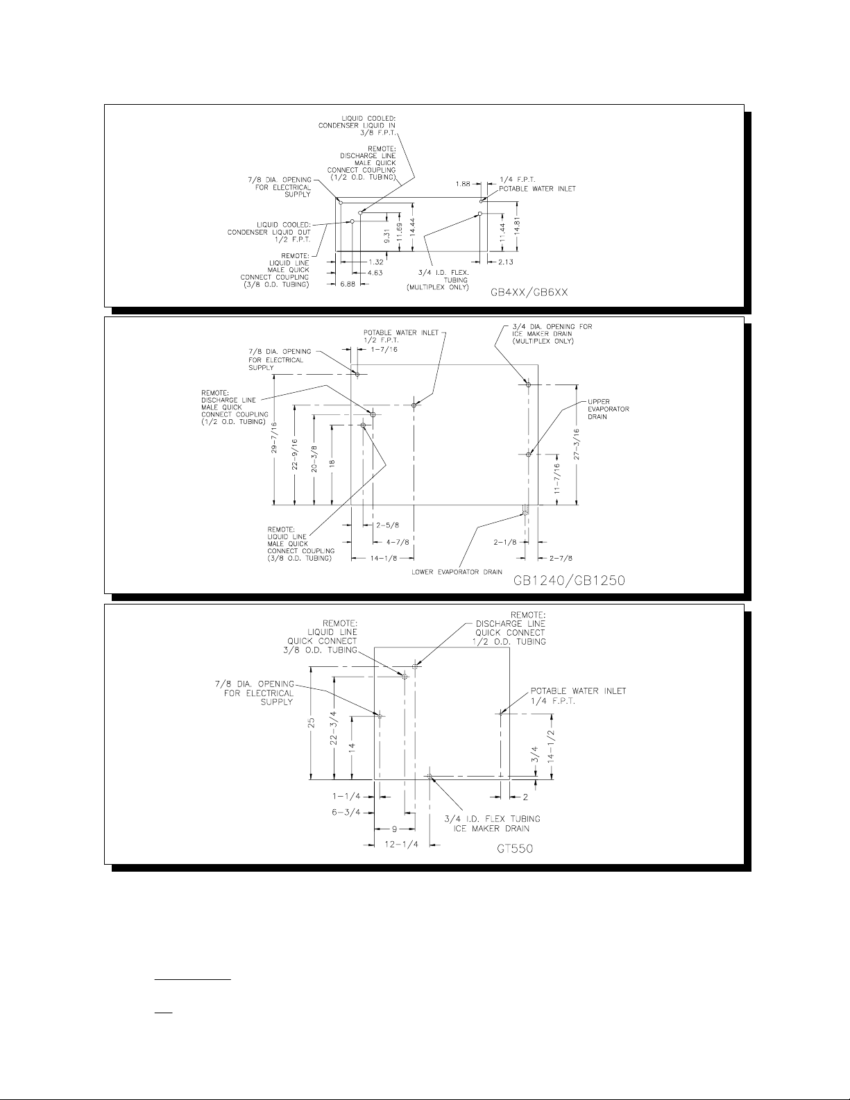
4. A single circuit condenser installation, which uses one line set, will require a
1-3/4" dia. hole to pass the lines through a ceiling or wall. The lines for a 2
circuit condenser require a 2" dia. hole.
5. Each line set consists of a 3/8" l iquid line, and a 1/2" insulated discharge li ne.
Connect the 3/8" line to the lower (liquid) fitting on the condenser, and to the
"Refrigerant In" on the ice maker. The 1/2" line connects to the upper (inlet)
fitting on the condenser, and the "Refrigerant Out" on the ice maker.
6. Each fitting on the line sets, condenser and ice maker is self-sealing, and
should be tightened 1/4 turn more than hand tight. Always use a backup
508 1044 01 Rev. 3-02
-1-
Page 3
7. The condenser fan motor requires a separate 208-230 volt, 60 Hz, single phase
power supply whi ch complies with all appli cable code requi rements. The system
is designed for continuous fan motor operation. If desired, a condenser fan
cycling control may be installed to stop the fan during cuber off-cycles.
Suggested pressure calibrations are approx. 250 psig ON/220 psig OFF.
CAUTION: For multiple-circuit installations, a separate pressure control must
be installed on each circuit, and all of the controls must be parallel-wired so that
all controls must be open to stop the fan.
508 1044 01 Rev. 3-02
-2-
Page 4

8. The refrigerant lines should be routed inside the building or otherwise
mechanically protected wherever possible.
In cold weather operation, the liquid return line (3/8") may sweat or frost. If this
is objectionable, insulation may be installed on the liquid line inside the bui lding.
INSTALLER NOTE: There is no electrical interconnection provision i n "R" Models for
the condenser fan.
Ampacity: Minimum ampacity does not indicate typical running current value. Refer to
equipment NAME PLATE data. Use minimum ampacity value for sizi ng branch circuit
conductors up to 25 feet length. For conductor length over 25 feet up to 100 feet,
increase 1 AWG size. Over 100 feet requires 2 or more AWG size increase.
Branch circuit protection: Proper protection must be provided by either fuse(s) or
HACR type circuit breaker(s). Each ice maker must be provided with a separately
protected circuit with no other load(s). A fused disconnect installed adjacent to each
ice maker is recommended (must be supplied by the installer), and may be required by
local codes. NORMAL protector size is based on rated vol tage and operati on at lower
than extreme temperature li mits. When branch circui t conductors are sized to permit,
increasing the protector size (up to the specified maximum) may avoid nuisance
protector opening under harsh operating conditi ons.
Remote condenser models from the factory carry a minimal charge and will likely
require an additional refrigerant charge to accommodate all condenser ambient
temperatures and/or the volume potentially contained in refrigerant lines and
condensers. There is a label on the receiver that indicates factory charge and the
maxi mum c har ge, along with a space to write in the total system charge. Ice makers
are provided with re-sealable refrigerant line connection coupli ngs.
All models are intended FOR INDOOR USE ONLY with PERMANENT CONNECTION
TO THE FIELD ELECTRICAL SUPPLY. The remotely-installed condensers supplied
by Kold-Draft® may be installed outdoors, and they require a separate electrical
supply.
Other operating condition requirements:
Ice maker ambient air temperature: MINIMUM 45°F.; MAXIMUM 90°F.
Remote condenser ambient air temperature: SEE CHART BELOW
HIGH AMBIENT
APPLICATION
(OVER 110
GB454
GT550
GB650
GB12501075, 1/4, 2SINGLE CIRCUIT
}
F.)
PART
NUMBER
GBB-02223-B
GBB-02413-B
GBB-02425-B
GBB-02426-B
CONFIGURATION
2 TON
3 TON
3 TON
5 TON
FAN MOTOR
RPM, HP, F LA
1075, 1/4, 2TWO CIRCUIT
NORMAL AMBIENT
APPLICATION
(UNDER 110
GB454
GT550
GB6501075, 1/4, 2TWO CIRCUIT
GB12501075, 1/3, 3.5TWO CIRCUIT
}
F.)
508 1044 01 Rev. 3-02
-3-
Page 5

Kold-Draft® Remote Condenser Single Evaporator Cuber Charging Requirements
®
Kold-Draft
Remote Condenser Dual Evaporator Cuber Charging Requirements
{
Charts based on 30 ft. of 1/2" O.D. discharge (15 ft. exposed to ambient temperature
under 70} F.) and 30 ft. of 3/8" O.D. liquid return lines, at 20} F., T.D.
{
Lines over 50 ft. are not recommended.
{
Minimum Condenser Height: Condenser must be installed above refrigerant line quick
connects at rear of ice machine. No part of the refrigerant lines, between the cuber
and the condenser, should fall below this point except for a trap directly behind
cuber.
{
For Condensers other than Kold-Draft®, the installer must determine the condenser
liquid vol ume at minimum operating temperature.
ˆFor Single Evaporator Cubers, the basic charge is 1-3/4 lbs. To this add the
condenser liquid volume calculation and the line charge calculation from Line Length
Correction Chart for the minimum total charge.
ˆFor Dual Evaporator Cubers, the basic charge is 3 lbs. To this add the condenser
liquid volume calculation and the line charge calculation from the Line Length
Correction Chart for the minimum total charge.
CAUTION:
{
RISK OF PROPERTY DAMAGE, EQUIPMENT FAILURE, OR FIRE.
{
Failure to comply with all install ation specificati ons and instructions may cause
erratic operation and the risk of damage or fire.
-4-
508 1044 01 Rev. 3-02
Page 6

REFRIGERANT CHARGE, MODEL NUMBER
Oz. (R-404A) GB454R GB650R GB1250R GT550R
--------------------------------------------------------------------------------------------------------------------------------------
Factory: 84 84 112 84
Maximum: 208 208 272 208
CAUTION: REFRIGERANT CHARGES MUST BE ACCURATELY WEIGHED.
NOTE: The compressor will start immediately when power is applied, regardless of
the "ICE-OFF-WASH" switch position, if the low-side pressure is at or above the
pump-down controll er cut-in setti ng. Disconnect the BLUE contactor coil wire for initial
warm-up period. Be sure that the compressor stops when the low-side pressure is
between 5 and 15 psig.
CAUTIONS
1. Try to keep the compressor warmer than the condenser. In most installations,
the ice maker runs enough so that residual motor heat minimizes liquid
migration to the crankcase. If the ice maker is in a cool location, or will be OFF
for extended periods, a crankcase heater must be used (All Models include a
Factory-installed crankcase heater).
2. Avoid placing the condenser in the exhaust air stream of other roof-top
equipment. Stay away from kitchen exhaust fans to prevent grease
accumulation on the fins. Use a curb, which extends above the deepest
508 1044 01 Rev. 3-02
-5-
Page 7

expected pond in the condenser area of the roof. A 3" pond can cut air flow in
half if a curb is not used.
508 1044 01 Rev. 3-02
-6-
 Loading...