

Page 1
KOLD-DRAFT
CLASSIC
GB430/440/450
GB1220/1240/1250
KOLD-DRAFT
Ice Machine Products
®
GB630/640/650
Multiplexing Installation Instructions
®
1525 East Lake Road, Erie, PA 16511-1088
814/453-6761
FAX 814/455-6336
©2004 KDIndustries, Inc., Erie, PA U.S.A.
Printed in U.S.A. 3/04
508 1014 01
A Tradition of Excellence In Ice Equipment.
Page 2
KOLD-DRAFT MULTIPLEXING INSTALLATION INSTRUCTIONS
Section I
STACKING NEW GB CLASSIC UNITS ABOVE NEW GB CLASSIC UNITS
AND OLD GB CLASSIC UNITS ABOVE NEW GB CLASSIC UNITS
CAUTION:
RISK OF PERSONAL INJURY, PROPERTY DAMAGE, EQUIPMENT
FAILURE, OR FIRE.
Refer all maintenance to qualified personnel.
Never operate this equipment with covers, panels, or other parts removed
or not properly secured.
Use a suitable lifting means and be careful of sharp edges.
NOTE: Please refer to Section II of these instructions for installing a New GB Classic
unit above an Old GB Classic unit.
1. Remove cabinet panels from upper and lower ice makers.
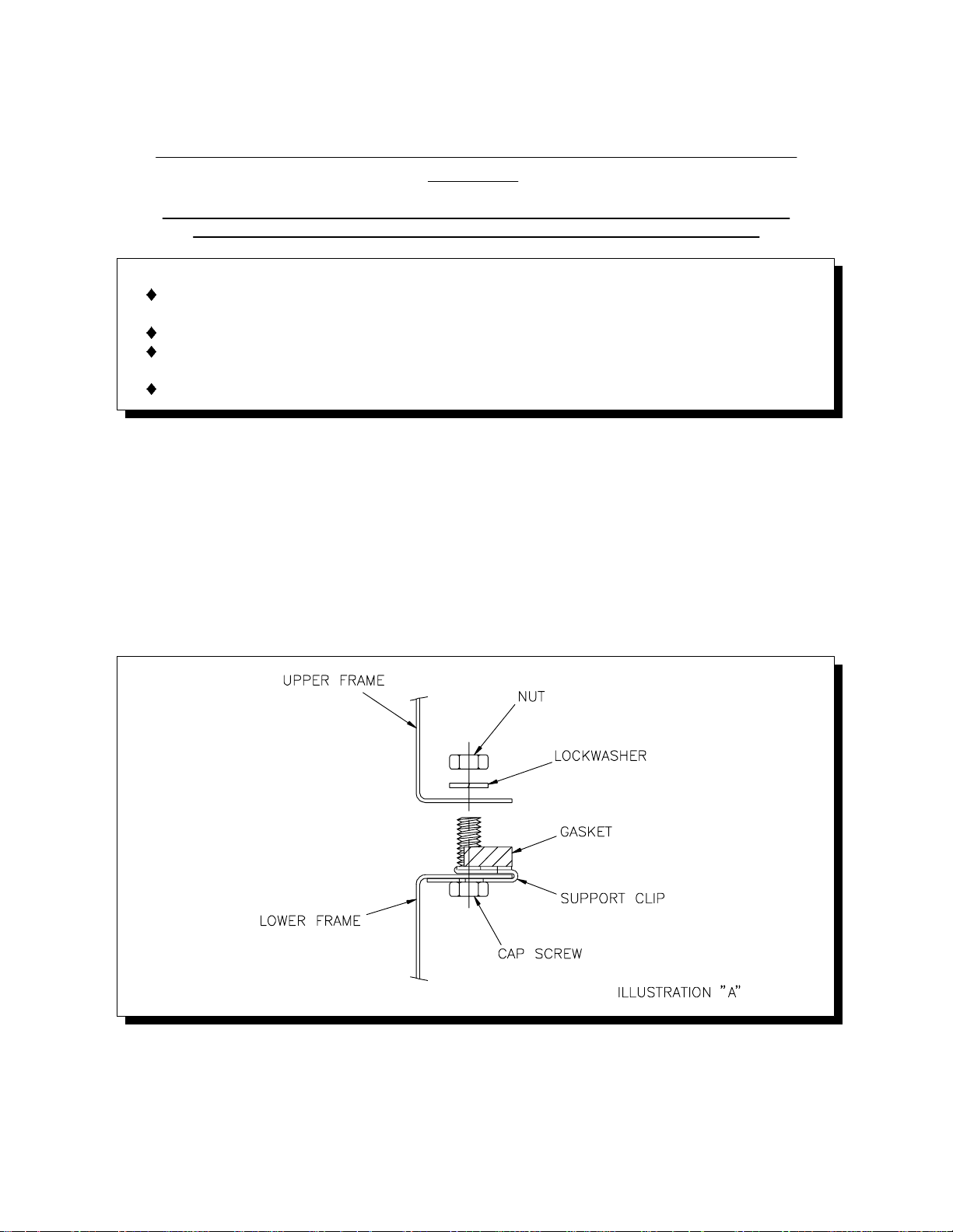
2. Mount support clips on top side flanges of lower ice maker frame and position
so the clip holes are aligned with the holes in the frame. (See Illustration "A")
The lower flange of the front support clips must slide into the space between the
top side flange of the ice maker and the top flange of the electrical box.
3. Apply gasket supplied with stacking kit to lower ice maker frame and cut to fit.
(See Illustration "B") Place gasket over the support clips already in position and
pierce the gasket where it covers the mounting holes.
508 1014 01 Revised 5/99
- 1 -
Page 3
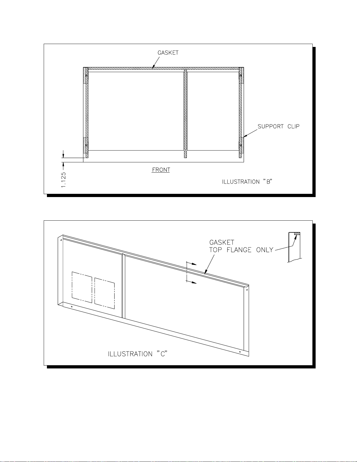
4. Apply gasket to the top inside flange of the lower ice maker front cabinet panel.
(See Illustration "C")
5. On Installations with Old GB Classic Units it is necessary to drill 2 - 5/16" dia.
holes and enlarge 1 - 3/16" dia. hole to 5/16" dia. in the bottom of the Old
Classic Frame. (See Illustration "D") The transformer box will have to be
moved temporarily in order to do this. The (2) right side holes can be drilled
through the cond. unit pan from the underside, using the existing frame holes as
a guide.
508 1014 01 Revised 5/99
- 2 -
Page 4

6. Position upper ice maker on lower unit and align mounting holes. Install cap
screws, lock washers and nuts. (See Illustration "A") CAUTION: Support upper
unit until all fasteners are secured.
7. Install the upper ice maker drain pan and ice chute. Connect the drain hose
elbow assembly to the drain pan and route the drain hose through the rear of
the lower ice maker. If the Old GB Classic drain pan does not have a hose
flange, exchange it with the pan from the New GB Classic unit.
8. Route upper ice maker bin thermostat capillary tube or probe wire down to the
lower ice maker chute opening for positioning. Keep capillary tube or wire
toward front of partition wall out of the path of falling ice. Stacking a third ice
maker will require a bin thermostat with a longer capillary tube (New GB Classic
Unit) or an extension cord (if Old GB Electronic unit). Consult factory for more
information.
9. The stainless steel Multiplex Ice Chute provided with 102 1207 01 GB Model
Stacking Kits is to be installed in all except the TOP cuber in the stack. Install
the Multiplex Ice Chute (see instructions at end) and side cabinet panels. On
some early New GB Classic units it may be necessary to crimp the back
catches of the side panels on the lower ice maker so the panel is held tight to
the frame.
10. Follow start-up instructions, included with ice maker, to complete the
installation.
508 1014 01 Revised 5/99
- 3 -
Page 5

KOL
D
-DRAFT
MULTIPLEXING INSTALLATION INSTRUCTIONS
Section II
Use a suitable lifting means and be careful of sharp edges.
STACKING NEW GB CLASSIC UNITS ABOVE OLD GB CLASSIC UNITS
CAUTION:
RISK OF PERSONAL INJURY, PROPERTY DAMAGE, EQUIPMENT
FAILURE, OR FIRE.
Refer all maintenance to qualified personnel.
Never operate this equipment with covers, panels, or other parts removed
or not properly secured.
1. Remove cabinet panels from upper and lower ice makers.
2. Mount inspection panel support angle to top front frame rail of lower (Old
Classic) unit with #8-32 screws, nuts and lockwashers provided. (See
Illustration "A")
3. Apply gasket supplied with stacking kit to lower ice maker frame and cut to fit.
Pierce gasket where it covers the mounting holes. (See Illustration "B")
508 1014 01 Revised 5/99
- 4 -
Page 6

4. Install (4) 1/4-20 cap screws up through mounting holes of lower ice maker and
fasten with 4 nuts.
5. Position upper ice maker over lower unit and lower in place. Secure with 4
nuts. (See Illustration "C") CAUTION: Support upper cuber until all fasteners
are secured.
6. Route upper ice maker bin thermostat capillary tube through grommeted hole in
the partition wall, down to the lower ice maker chute opening for positioning.
Keep capillary tube toward front of partition wall out of the path of falling ice.
Stacking a third ice maker will require a bin thermostat with a longer capillary
tube. Consult factory for more information.
7. Install the upper ice maker drain pan and ice chute. Connect the drain
hose-elbow assembly to the drain pan and route the drain hose through the rear
of the lower ice maker. If a 1" hole has not been provided in the rear gusset of
the lower ice maker it will have to be provided by the installer. (See Illustration
"D")
8. Install the Multiplex Ice Chute (see instructions at end) and side cabinet panels.
Follow start-up instructions included with ice maker to complete the installation.
508 1014 01 Revised 5/99
- 5 -
Page 7

508 1014 01 Revised 5/99
- 6 -
 Loading...