

Page 1
KOLD-DRA FT
CLASSIC
AKD-125
KOLD-DRAFT
Ice Machine Products
®
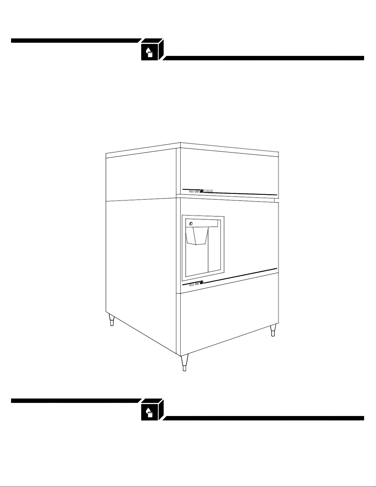
AKD-125-FF
ICE DISPENSER
Installation & Operation Instructions
1525 East Lake Road, Erie, PA 16511-1088
814/453-6761
FAX 814/455-6336
©2004 KDIndustries, Inc., Erie, PA U.S.A.
Printed in U.S.A. 3/04
508 1036 01
A Tradition of E xcellence I n I ce Equipment.
Page 2
Installation and Operation Instructions
®
for Kold-Draft
CHECK FOR FREIGHT DAMAGE BEFORE PROCEEDING: Even though damage to
the carton may not have been evident, check for hidden damage and contact freight
carrier immediately if necessary to file a claim.
THIS EQUIPMENT MUST BE INSTALLED IN COMPLIANCE WITH THE
APPLICABLE FEDERAL, STATE/PROVINCE AND/OR LOCAL PLUMBING,
ELECTRICAL AND HEALTH/SANITATION CODES AND REQUIREMENTS.
CAUTION:
{
RISK OF PERSONAL INJ URY, PROPERTY DAMAGE, EQUIPMENT FAILURE
OR FIRE.
{
Refer all maintenance to qualified personnel .
{
Never operate this equipment with covers, panels or other parts removed or not
properly secured.
{
Warn all users to clean up spi llage immediately, and report any apparent
leakage or unusual sounds to maintenance personnel.
{
Proper installati on must include Kold-Draft® GT Series Ice Cuber mounted
AKD-125 Ice Dispenser
Page 3

INSTALLATION
NOTE: Refer to ice cuber instructions before proceeding.
1. CAREFULLY remove the carton from the dispenser.
2. If the dispenser is to be mounted on the 6" legs provided, carefully place the unit
on its back and install the legs in the threaded mounting holes.
3. Position the dispenser maintaining the minimum clearances specified in the
cuber instructions.
4. Level the dispenser by adjusting the legs, or by shimming if the unit is to be
sealed to the floor. If gaps due to shims are greater than 1/8 inch, i nstall a cove
molding around the dispenser bottom. Seal the dispenser or molding to the floor
with NSF Certified RTV sealant (Dow-Corning RTV 732 or equal).
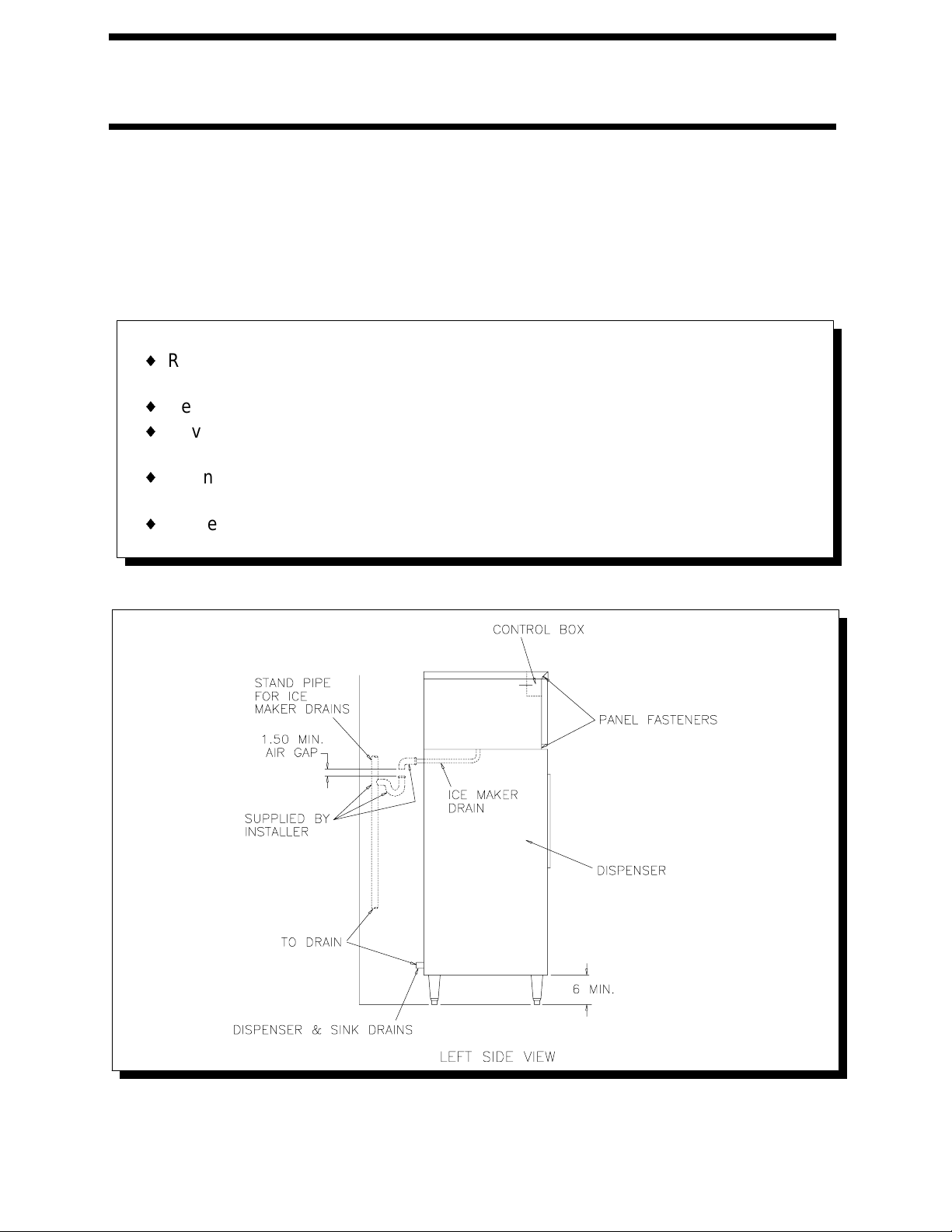
5. Electrical and drain locations are shown below. All dimensions are in inches.
6. Install gasketing on top of dispenser. (See Illustration "A")
7. Remove the cuber cabinet panels, lift and position cuber on top of gasketed
dispenser and align mounting holes. Install cap screws and lockwashers.
CAUTION: support cuber until all fasteners are secured.
508 1036 01
- 2 -
Page 4

8. If the GT cuber that you are mounting on the AKD does not have the hole in the
drain pan support, you must do the following:
A) Drill out the pop rivet, on the drain pan support that is nearest to the right side
of the cuber, with a #27 (.144") drill.
B) Attach the bracket to the drain pan support with the s.m. screw provided.
C) Slide the S.S. tube through the hole in the bracket.
D) Run the bin thermostat cap tube along the right side of the cabinet, then into
the S.S. tube. Allow the tip of the cap tube to protrude slightly past the end of the
S.S. tube (See Illustration "B").
9. If the GT cuber has the hole in the drai n pan support, then slide the S.S. tube
through the hole in the drain pan support, route the bin thermostat cap tube
along the right side of the cabinet and through the S.S. tube (See illustration
CAUTION:
{ Route bin thermostat cap tube away from moving parts.
"C"). The tip of the bin thermostat cap tube should protrude slightly past the end
of the S.S. tube.
INSTALLATION SPECIFICATIONS
CAUTION:
{ Risk of property damage, equipment failure or fire. Comply with all installation
specifications for safe operati on.
508 1036 01
- 3 -
Page 5

The AKD-125 Ice Dispenser is designed for 115 volt 60 hz. operation. The AKD-125-FF is
designed for 230 volt 50 hz. operation.
Refer to equipment name plate data for current value and maximum fuse size. This unit must
be provided with a separate, properly protected circuit with no other loads. A fused disconnect
installed adjacent to the dispenser is recommended (to be supplied by installer), and may be
required by local codes.
This Dispenser is intended for indoor use only with permanent connection to a field
electrical supply. This model is intended to be installed only in conjunction with a
Kold-Draft
®
“GT” Series Ice Cuber.
DISPENSER MAINTENANCE
Every 6 Months Minimum
CLEANING
Always clean the ice maker first, following the ice maker cleaning instructions.
CAUTION:
{ Risk of personal injury, equipment damage or contamination of the dispenser
bin.
{ Do not use ammonia solutions or strong detergents in cleaning the dispenser.
{ Never use appliance polishes, finish preservatives or cleaners in areas that
contact ice.
Remove all ice from the dispenser before
starting the cleaning procedure.
1. Remove ice maker top and front panels and drain pan/chute.
2. Loosen the wing nuts on the upper bearing clamp and pull it off to release the top of
the auger.
3. Pull the auger up at least 1" on its axis to clear the lower drive mechanism and remove
it through the front of the ice maker.
4. Wash the bin interior with a solution of 2 tablespoons of baking soda per quart of clean
}
water (14 0
maker. Use a long handled brush to reach the bottom of the bin if needed.
F. max.). The dispenser bin can be accessed through the front of the ice
5. Wash the sink interior with the baking soda solution and wipe dry with a clean cloth.
NOTE: The spout and spout closure should be removed for thorough cleaning in the
solution container and then replaced.
6. Rinse with clean tap water.
7. Replace the auger, making sure that it is fully engaged with the lower drive mechanism.
Install the upper bearing clamp and tighten the wing nuts.
8. Sanitize all ice contact surfaces including the ice spout and spout closure with a
solution of 1 teaspoon 5-1/4% sodium hypochlorite (chlorine bleach) per quart of clean
tap water (minimum 100 PPM free chlorine). A spray bottle will facilitate this pro cess.
Pour the unused sanitizing solution over the auger and down the storage area drain.
9. Exterior surfaces may be cleaned by standard methods suitable to the stainless steel
finish.
10.Replace the ice maker front and top panels before reconnecting the power supply.
508 1036 01
- 4 -
Page 6

508 1036 01
- 5 -
 Loading...