

KOKUA LIKEtoBIKE 20 Assembly And Operating Instructions Manual
ASSEMBLY AND OPERATING INSTRUCTIONS
LIKEtoBIKE 20
Please read this manual carefully before using the LIKEtoBIKE for the rst time!
The assembly must be done by an adult!
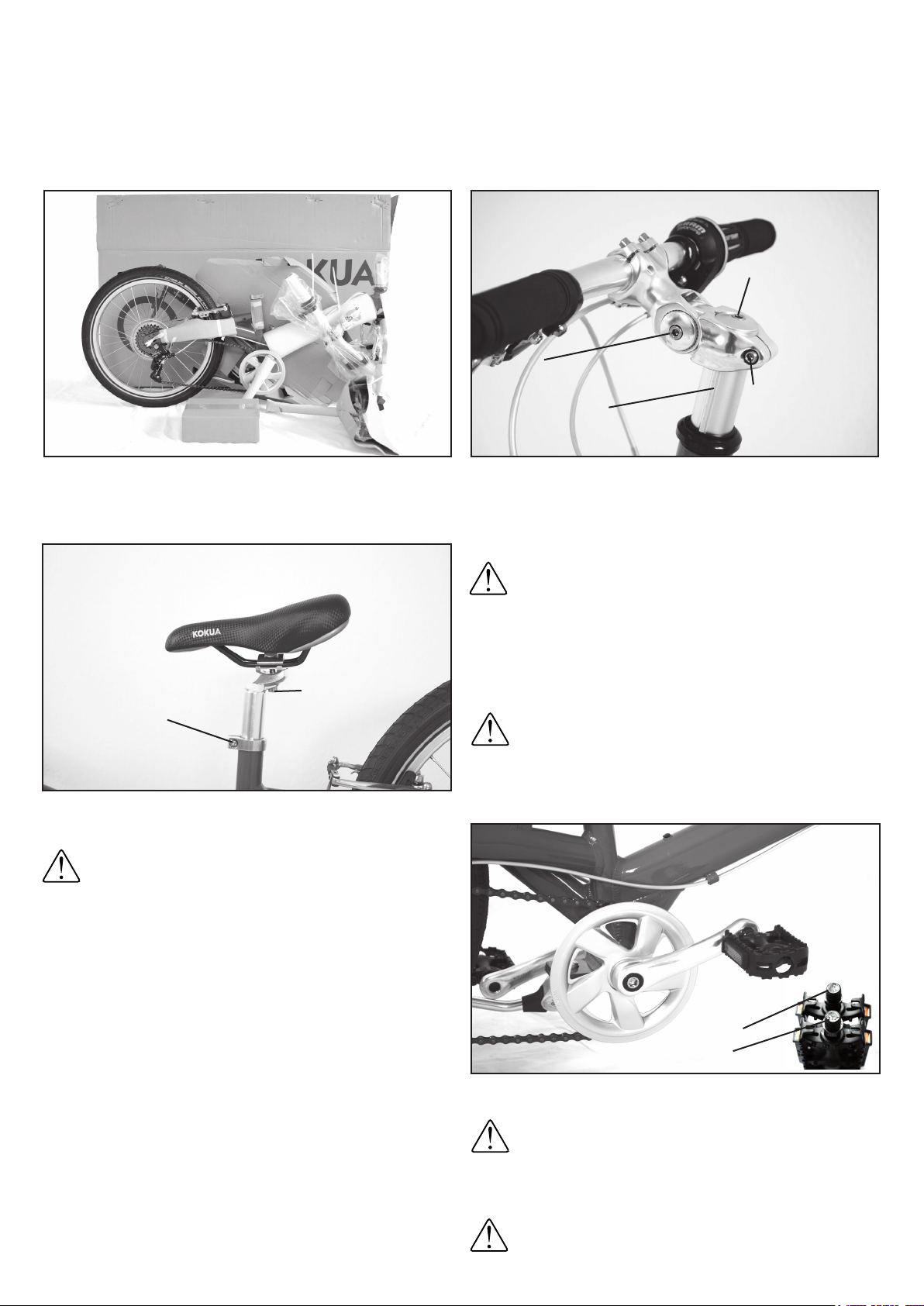
1. Remove all packaging materials. Contents of the enclosed accessory box are: Pedals, hexagon tool (Allen key) (4mm,5mm,6mm),
Front and Rear Reectors, Touch-up paint, Instructions.
2. After loosening the seat post clamp screw, slide the seat post
into the seat tube.
Important: Please note the minimum insertion depth of
the seat post! This is indicated by a line marked on the
seat post! The seat post must not be pulled out beyond
this mark, otherwise a secure connection to the down
tube is not guaranteed! The saddle can be adjusted in the lon-
gitudinal direction and inclination after loosening the saddle
fastening screw. Then tighten this screw again!
Adjusting the correct saddle height: Place a pedal in the lowest
position. If the child is sitting on the saddle, the child must be able
to touch this pedal with his heel (outstretched leg). Make sure that
the childs hips stay level and do not tip over to the side!
Seat post
clamping screw
Right Pedal
Left Pedal
4. Now mount the pedals. Turn the pedal axles by hand until snug!
Then tighten with a 15 mm wrench.
Important: The right pedal is mounted clockwise, the
left pedal counterclockwise! The pedals are marked on
the pedal axle with an „R“ for the right pedal and an „L“
for the left. It is important to remember this if you need to
loosen the pedal axle someday. So that the pedals can easily be
loosened again later, grease them lightly before mounting.
After the rst long ride please check that the pedals are
seated rmly! Loose pedals could damage the thread of the
cranks or cause a fall!
3. 3. Insert the stem with the already mounted handlebar onto the
steering tube.
Now align the handlebar in the direction of travel at the desired
height and tighten the height adjustment screw with a 5 mm Allen
key (torque 10 Nm).
Under no circumstances may the stem be mounted over the
upper edge of the steering tube!
After loosening the angle adjustment screw, you can ne
tune the handlebar position by changing the stem angle. Then retighten the angle adjustment screw (torque 10 Nm).
Use the headset adjustment screw to adjust the headset.
Very important: With this screw you adjust only the
headset clearance! This screw is not used to attach the
stem!
Adjustment for
headset clearance
(NOT TO FIX THE
STEM!)
Angle adjustment
screw
Steering tube
Height
adjustment screw
Saddle fastening
screw
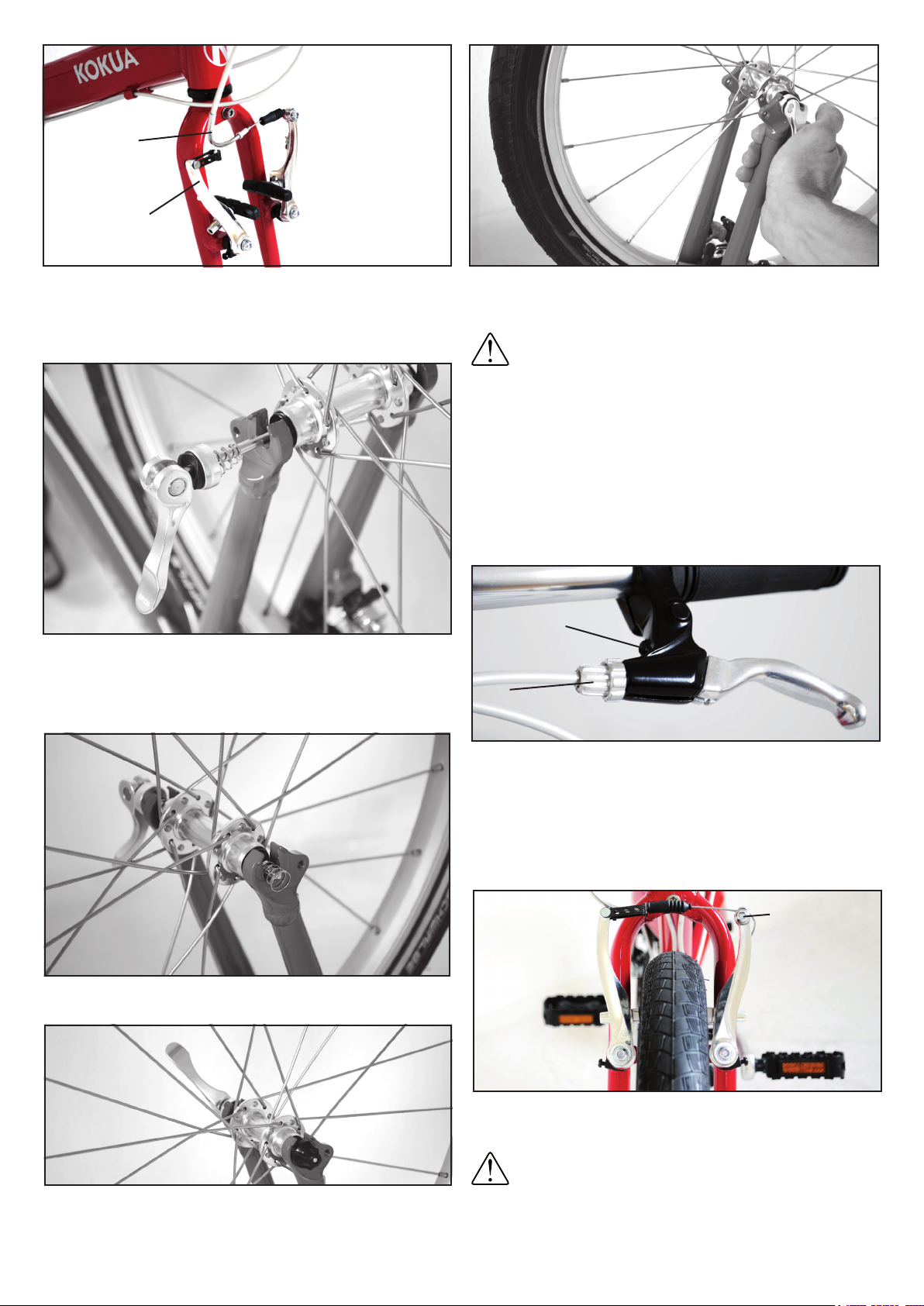
7. 7. The distance between the brake pads and the rim can be
changed by slightly loosening the brake cable clamp screw and
slightly reducing or increasing the tension of the cable.
Then tighten the brake cable clamp screw again! Wear
of the brake pads may necessitate a readjustment of
the brake. Small adjustments can be done by using the
brake adjustment screw on the brake lever.
6. The brake lever/handlebar distance can be adjusted to the
child‘s reach with the brake lever adjustment screw. Afterwards
the correct distance of the brake pad to the rim may have to
be reset! They should be as close as possible to the rim, but
not touch until the lever is pulled.
The left brake handle is assigned to the front brake, the right to the
rear brake!
Center the rim and close the quick release lever so that it is parallel
to the left fork.
Important: The quick-release lever must be very difcult to swing into the closed position! Press the quick
release lever into position with the ball of your thumb
while you wrap your ngers around the back of the fork!
If the quick release lever can be turned in the closed position,
the clamping force is not sufcient. The bike could come loose during the ride! Open the quick-release lever again and pull
the clamping nut a little tighter. Then close the quick release
lever as described above! Do not forget to reinsert the brake
cable guide tube and check the brakes!
5. To install the front wheel, the front brake must be released. By
squeezing the two brake arms and pulling gently on the brake
cable guide tube, the brake cable can be unhooked.
Now insert the wheel into the fork so that the axle ends to the right
and left of the hub body are correctly seated in the ends. Remove
the tension nut and a spring from the quick release axle. Now
insert the quick-release axle from the left side through the hollow
axle of the wheel hub.
Then push the second spring onto the quick-release axle.
Pull the quick release clamp open.
Tighten the quick release nut until it touches the dropout.
Brake cable
guide tubes
Brake Arm
Brake lever
adjustment screw
Brake
adjustment screw
Brake cable
clamp screw
 Loading...