

Koike PNC-12 EXTREME Operation Manual

PNC-12 EXTREME
Portable CNC Cutting Machine
Operation Manual – Version
T30003406
For every person who will be engaged in operation and maintenance
supervision, it is recommended to read through this manual before any
operations, so as to permit optimum operation of this machine.

INTRODUCTION
Thank you very much for purchasing the PNC-12. This manual outlines the information you will need to
get the product properly, safely and effectively used with the fewest possible complications. Please take
a few moments to read this manual thoroughly to understand how to operate and maintain the machine.
Other partner’s cooperation on worksite is essential for safety and smooth operation. Please make sure
to read and understand the manual, and take all safety precautions as necessary.
SAFETY PRECAUTION
S
This product is designed to be safe, but it can cause serious accidents if not operated correctly. Those
who operate and repair this machine must read this manual thoroughly before operating, inspecting and
maintaining the machine. Keep the manual near the machine so that anyone who operates the machine
can refer to it if necessary.
Do not use the machine carelessly without following the instructions in the manual.
Use the machine only after you completely understood the contents of the manual.
If any explanation in the manual is difficult to understand, contact our company or sales service office.
Keep the manual near by at all times and read it as many times as necessary for a complete
understanding.
If the manual becomes lost or damaged, place an order with our company or sales service office for a
new one.
When transferring the machine to a new owner, be sure to hand over this instruction manual as well.
Q
UALIFICATIONS FOR MACHINE OPERATO
R
Operators and maintenance staff of this machine must completely understand the contents of the
instruction manual and they must have one of the following certificates:
1. Gas welding foreman license
2. Gas welding training courses Certificate
3. Certificate recognized by the Ministry of Labor
PNC-12 EXTREME
2
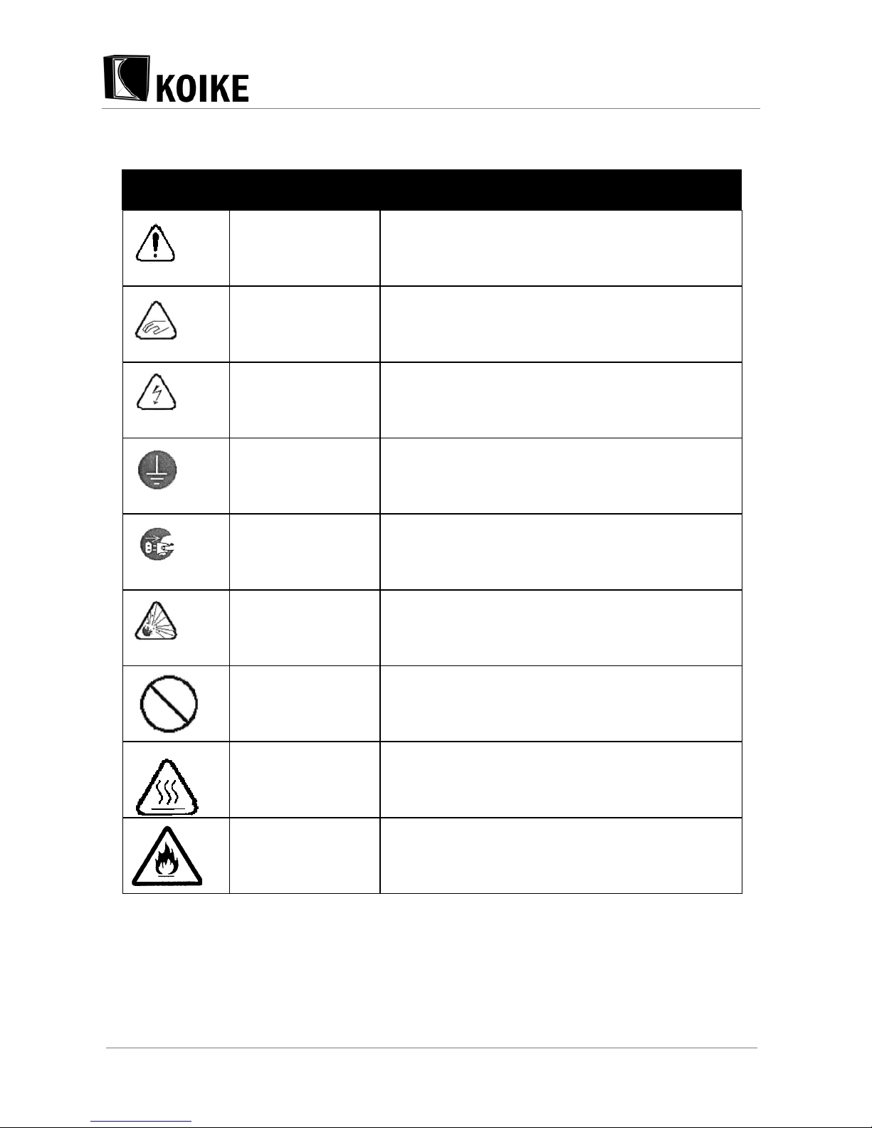
Symbol Title Meaning
General General caution, warning, and danger.
Be careful not to get
your fingers caught.
Possible injury to fingers if caught in the insertion
part.
Caution: Electric
shock!
Possible electric shock under special conditions.
Ground this
equipment.
Operators must ground the equipment using the
safety grounding terminal.
Pull out the power
plug from the outlet.
Operators must unplug the power plug from the
outlet when a failure occurs or when there is a danger
of lightning.
Caution against
bursting
Possible bursting under certain conditions.
General General warning.
Caution: Hot!
Possible injury due to high temperature under certain
conditions.
Caution: Ignition! Possible ignition under certain conditions.

PNC-12 EXTREME
3
TABLE OF CONTENTS
1 Safety Information..................................................................6
1.1 General machine safety precautions...............................................6
1.1.1 Machine safety..................................................................................................6
1.1.2 Safety clothing ..................................................................................................6
1.1.3 Operation and handling safety precautions....................................................... 7
1.1.4 Electrical system precautions ...........................................................................7
1.1.5 Maintenance and inspection precautions.......................................................... 7
1.2 Gas cutting safety precautions........................................................7
1.2.1 Prevention of explosion..................................................................................... 8
1.2.2 Pressure regulator safety precautions ..............................................................8
1.2.3 High-pressure gas cylinder safety precautions .................................................8
1.2.4 Safety precautions for hoses ............................................................................8
1.2.5 Safety precautions for fire .................................................................................8
1.2.6 Safety precautions for skin burns......................................................................8
2 Brief Introduction to Cutting Machine..................................9
2.1 Main Features....................................................................................9
2.2 Wide Usage......................................................................................10
2.3 Equipment Composition.................................................................10
2.4 Cross bar types and specification.................................................11
2.5 Longitudinal rail types and specification......................................11
3 Machine Installation .............................................................11
3.1 Overview ..........................................................................................11
3.2 Machine Installation........................................................................11
3.2.1 Check components in the delivered box. ........................................................12
3.2.2 If optional plasma device is purchased, following is included. ........................12
3.2.3 Connect Main Body Unit to Longitudinal Guide Rail .......................................14

PNC-12 EXTREME
4
3.2.4 Installation of Cross Bar.................................................................................. 14
3.2.5 Assembly of Motorized Up/Down Device, Distributor and Solenoid Valve Unit
15
3.2.6 Connection......................................................................................................15
3.2.7 Connection to Gas Supply ..............................................................................15
3.3 installation of Plasma Cutting to Standard Machine (with arc
voltage control) ..............................................................................16
3.3.1 Step 1: replace torch unit ................................................................................16
3.3.2 Step 2: install arc voltage control .................................................................... 17
3.3.3 Step 3: Install 8P motorized Up/Down control cable and 3P motorized
Up/Down control cable:............................................................................................ 17
3.4 Addition of Plasma Cutting in Standard Machine (with arc
voltage regulated up).....................................................................18
3.5 Addition of Oxy-Fuel Cutting Function in Plasma Model............18
3.6 Gas Supply of Relevant Devices....................................................18
3.7 following options are available upon customer’s request..........18
3.8 Control Panel...................................................................................19
4 Brief Introduction to MACHINE Parts .................................21
4.1 Mechanical Movement Structure...................................................21
4.2 Fluid System....................................................................................21
5 Machine Maintenance and Preservation ............................21
5.1 Machine Cleaning............................................................................21
5.2 Machine Lubrication .......................................................................22
5.3 Machine Adjustment .......................................................................22
5.4 Cleaning of Cutting Nozzle.............................................................22
6 Operation of Cutting Torch..................................................22
6.1 Shutdown of Cutting Torch ............................................................22

PNC-12 EXTREME
5
6.2 Operation Procedures of CNC Cutting Machine ..........................23
7 Warranty Instructions...........................................................24
8 Cutting Data ..........................................................................25
9 Wiring Diagram.....................................................................27
10 Part s list.................................................................................29
10.1 Transmission Main Body................................................................29
10.2 Control Cabinet and Main Body Protection..................................30
10.3 Cross Arm........................................................................................32
10.4 Track Foundation ............................................................................33
10.5 Flame Unit........................................................................................34
10.6 Plasma Unit (Optional)....................................................................36
10.7 Control Cabinet ...............................................................................37

PNC-12 EXTREME
6
1 SAFETY INFORMATION
Disregard the basic safety rules can cause many accidents during operation, inspection, and
maintenance. Carefully read, understand, and master the safety measures and precautions described in
this instruction manual of the machine before operating, inspecting, and maintaining the machine. The
safety messages are classified as indicated on the machine safety labels:
WARNING
This word is used in a warning message and a warning label is positioned at places that could cause
injury or serious accident.
DANGER
The danger symbol indicates that serious injuries and major damage will be possible if not avoided. It is
also used as a warning label.
CAUTION
This word is used in a caution message and a caution label is positioned at places that could cause slight
injury or machine damage. This is also used as a caution for frequent dangerous actions.
NOTICE SIGNS
This is a sign to show machine operators and maintenance engineers items that relate directly to
damage of machines and surrounding facilities and equipment.
1.1 GENERAL MACHINE SAFETY PRECAUTIONS
Read and fully understand the following important safety information:
1.1.1 Machine safety
The machine casing is mainly made of aluminum alloy to reduce weight. For this reason, be careful not to
drop a heavy item on the machine, or not drop the machine when carrying it, since the alloy is not
designed to withstand such impact.
When mounting hoses to the torch and distributor, tighten the nut with the attached wrench. After
mounting, be sure to check there is no gas leak with a detection liquid. If a gas leak is found, retighten the
nut firmly.
When fixing a tip to the torch, tighten the nut with the two wrenches attached. In addition, avoid damaging
the taper part of the tip since this may cause backfire.
1. Never disassemble the machine other than during maintenance and inspection. Otherwise,
malfunction will result.
2. Never remodel the machine. Remodeling is very dangerous.
3. When changing the travel direction, make sure that the direction switch is in the neutral (stop)
position, and operate the direction switch after the machine has stopped.
4. Always turn the power off when not used.
5. Never use the machine outdoors when the weather is wet. This will cause failure of the machine and
could cause a fatal accident by electric shock.
1.1.2 Safety clothing

PNC-12 EXTREME
7
Be sure to wear protector's gauntlets, goggles, helmet, and safety shoes during operation.
Avoid operating the machine with wet clothes or hands in order to prevent electric shock.
1.1.3 Operation and handling safety precautions
1. Read this instruction manual before operating the machine.
2. Mount and center the machine correctly and confirm correct motion before operation.
3. Prior to connecting the power plug with the socket, make sure the power switch in OFF position
(turn the switch clockwise or counterclockwise to the stop position).
4. Prior to operating the machine, check the safety of the surroundings to avoid accidents.
5. Never move the machine while the preheat flame is on.
6. When an operation is carried out at a higher position, be careful that the splashes and slugs may
hurt others at lower position.
7. Be sure that the clutch is in state of meshing before operation, any improper state may cause
accidents.
8. Be careful that the hands may be caught in erecting guide rail.
9. When cutting along the guide rail, be sure to fix the small guide roller properly.
10. Erect the preheat board properly to avoid affection to the guide rail.
11. To avoid that holder of torch from falling, use the bolt on the sliding holder to fix it.
12. Be sure to hold tight of handles in moving the equipment.
13. Prior to moving guide rail, be sure to move the equipment out of the guide rail.
1.1.4 Electrical system precautions
1. Be sure to check the input power voltage of the machine before operation. The input power voltage
should be in the range of +10% of the rated voltage. The machine should not be operated out of
this range.
2. Be sure to keep the layout of power cable reasonable, so that the cables will not be caught in the
equipment operation.
3. Be sure to ground the power cable or use a socket with earth wire.
Stop operation and turn off the power in the following cases, and ask a qualified electrician to repair
the machine.
a) Broken or abraded cables
b) When the machine has been in contact with water, or in case of liquid damage to the
machine.
c) Abnormal machine operation despite operating the machine according to the
instruction manual
d) Machine breakdown
e) Poor machine performance that requires repair
4. Periodically inspect the electrical system.
1.1.5 Maintenance and inspection precautions
1. Ask a qualified electrician to perform repair and inspection service.
2. Disconnect the power plug before inspecting and repairing the machine.
3. Maintain the machine periodically.
1.2 GAS CUTTING SAFETY PRECAUTIONS
Strictly observe the safety rules and precautions to ensure the safety of gas cutting operations. Operators
and supervisors MUST keep safety in mind.

PNC-12 EXTREME
8
1.2.1 Prevention of explosion
1. Never cut pressurized cylinders or hermetically sealed containers.
2. Ensure sufficient ventilation for gas cutting to prevent the air from becoming stale.
1.2.2 Pressure regulator safety precautions
1. Before starting operation, check that all pressure regulators are operating correctly.
2. Ask a skilled repair engineer to perform maintenance and inspection service.
3. Do not use pressure regulators from which gas is leaking, nor malfunctioning pressure regulators.
4. Do not use pressure regulators smeared with oil or grease.
1.2.3 High-pressure gas cylinder safety precautions
1. Never use broken cylinders or cylinders from which gas are leaking.
2. Install cylinders upright and take measures to prevent them from falling.
3. Use only for specified purposes.
4. Do not use the cylinders which smeared with oil or grease.
5. Install cylinders in a place free from heat, sparks, slag, and open flame.
6. Contact the distributor if the container valves will not open.
7. Never use a hammer, wrench, or other tools to forcibly open container valves.
1.2.4 Safety precautions for hoses
1. Use the oxygen hose for transferring oxygen gas only.
2. Replace cracked hoses or other hoses damaged by sparks, heat, unshielded fire, etc.
3. Install hoses without twisting.
4. To prevent breakage of hoses, take great care during operation and transportation.
5. Do not hold the hoses when moving the machine.
6. Periodically check the hoses for damage, leakage, fatigue, loose joints, etc, to ensure safety.
7. Cut hoses to the minimum possible length. Short hoses reduce hose damage and pressure drop, as
well as reduce the flow resistance
1.2.5 Safety precautions for fire
Take safety precautions to prevent fire prior to gas cutting. Ignoring hot metal, sparks, and slag could
cause a fire.
1. Keep a fire extinguisher, fire extinguish sand, bucket full of water, etc. ready on the site where gas
cutting is performed.
2. Keep flammables away from the cutting area to avoid exposure to sparks.
3. Always cool down steel plates that have become hot after cutting, as well as hot cut parts or scrap,
before bringing them close to flammables.
4. Never cut containers to which flammable materials are stuck.
1.2.6 Safety precautions for skin burns
Observe the safety precautions to prevent skin burns. Ignoring heat, spatter, and sparks during
operation could cause a fire or burned skin.
1. Do not perform cutting near flammables. (Move flammables well away from the sparks.)
2. Do not cut containers filled with flammables.
3. Do not keep lighters, matches, and other flammables nearby.
4. Flames from the torch will burn the skin. Keep your body away from the torch and tip, and check the
safety before operating the switches and valves.

PNC-12 EXTREME
9
5. Wear the correct protectors to protect your eyes and body.
6. Correctly tighten the tip to prevent backfire.
7. When fixing a tip to the torch, tighten the nut with the two wrenches attached.
8. If the tip is tightened excessively, it will be heated during cutting and tightened still more, making it
difficult to remove the tip.
9. Avoid damaging the taper of the tip since this may cause backfire.
10. Check with soapsuds for any leakage of gas from the connection part of the distributor, hose and
torch.
11. Be sure to check the following when igniting:
Install the torch on the torch holder before ignition.
Always wear the required protectors (gauntlets, helmet, goggles, etc.)
Check for any obstacles, dangerous materials and flammables near or in the direction of
cutting. Determine the gas pressure.
The gas pressure must be within the appropriate range. (For the gas pressure, refer to the
Cutting Data.)
12. The torch, tip and heat shield are heated to a very high temperature. Always wear gauntlets when
handling them. Also the surface after cutting is very hot so do not touch it even while wearing
gauntlets.
13. Do not move the machine when the preheat flame is on.
2 BRIEF INTRODUCTION TO CUTTING MACHINE
This cutting machine is a modern cutting device controlled by digital program. Besides the automation of
cutting operation, it also features high cutting precision, high material utilization rate and high production
efficiency. With the advancing of machine electronic technologies and computer technologies, CNC
cutting machine is taken seriously by a growing number of enterprises and is thus widely applied in the
production due to its favorable man-machine interaction operation interface, powerful auxiliary supporting
functions, and relatively low equipment investment.
2.1 MAIN FEATURES
Numerical Control Function
The numerical control function of this machine is same as that of large gantry-type CNC cutting machine.
It is capable of cutting any complicated plane figures. It applies to oxygen and gas flame cutting and
plasma cutting. It is as convenient and flexible as semi-automatic cutting trolley. This machine can be
moved at will without occupying any fixed yard.
Easy Programming
The programming jacking of this machine is simple. It cannot only conduct manual programming of
simple graphs but also implement the automatic programming of random and complicated graphs
through programming software presented with the machine. Interactive conversational mode is adopted
for this software. The graphic data is automatically switched. Manual coding is not required. After clearing
of part drawings mapped by using AutoCAD, DXF files will be directly accessed. Then, they will be
discharged through programming software. G code files required for cutting are directly generated after
selection of proper programming parameters.
Flexibility
PNC-12 EXTREME
10
Convenient and flexible file transmission and storage: USB interface is supported. The users may output
the files required for cutting to USB memory. Then, insert the USB memory to the USB interface of the
mini-type cutting machine to implement file transmission.
Simple Operation
Simple and convenient operation: during operation, this machine can be either used as a semi-automatic
trolley for manual cutting or used as a large CNC machine for automatic cutting.
2.2 WIDE USAGE
The machine can be widely used in industries like automobile, shipbuilding, petrochemical engineering,
boiler pressure vessel, engineering machinery and light-industry machinery. It is applicable for the cutting
and blanking of sheet metals like carbon steel (flame cutting), stainless steel, aluminum and copper
(plasma). This product is especially suitable for single-piece and batch production of profiled surfaces.
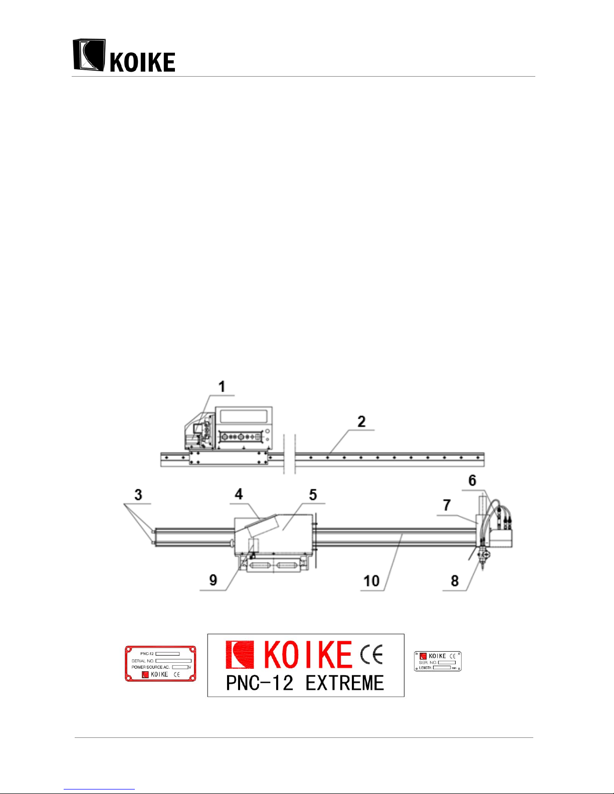
2.3 EQUIPMENT COMPOSITION
The main parts of this machine include main body, longitudinal and transverse driving devices, guide rail,
cutting torch component, gas supply system, electrical control system, plasma cutting devices, etc.. The
contour of the machine is shown as follows:

PNC-12 EXTREME
11
1 Transverse driving motor 6 Solenoid valve unit
2 Longitudinal guide rail unit 7 Motorized up/down device
3 Gas supply inlet 8 Oxy-fuel torch unit
4 Control system 9 Longitudinal driving motor
5 Main body unit 10 Cross bar unit
2.4 CROSS BAR TYPES AND SPECIFICATION
Effective cutting 1000L: full length of 1900mm
Effective cutting 1250L: full length of 2110mm
Effective cutting 1500L: full length of 2400mm
2.5 LONGITUDINAL RAIL TYPES AND SPECIFICATION
Effective cutting 1500L: full length of 2050mm
Effective cutting 2500L: full length of 3090mm
Effective cutting 3000L: full length of 3540mm
3 MACHINE INSTALLATION
3.1 OVERVIEW
In order to make sure the machine can be smoothly moved and operated, the machine must be placed
on a steel plate that is held steady without wobbling or the machine must be fixed. Meanwhile, it is
required to avoid placing the machine in the open air to assure its cutting quality and operating
performance.
3.2 MACHINE INSTALLATION
After receiving the Potable CNC cutting machine, the user shall count the article according to the packing
list and place it in a reliable position (note: Please keep USB memory for installing PNC-CAM (or
KAP-Jr.) safely). The machine is dismantled partially and is packed. After the equipment arrives at the
user’s site, the user is required to assemble those equipment by user itself. The assembly process is
shown as follows:
 Loading...