

Page 1
35 590 01 Rev. C
KohlerPower.com
TP 3.0, WP 2.0, WP 3.0
Trash Pump & Water Pump Owner's Manual
IMPORTANT: Read all safety precautions and instructions carefully before
operating equipment.
Ensure unit is stopped and level before performing any
maintenance or service.
Record product information to reference when ordering parts or obtaining warranty coverage.
Specifi cation
Serial Number
Purchase Date
EN
ESS
FRC
Page 2

2 35 590 01 Rev. CKohlerPower.com
California Proposition 65 Warning
Engine exhaust from this product contains chemicals known
to State of California to cause cancer, birth defects, or other
reproductive harm.
California Proposition 65 Warning
This product contains chemicals known to State of California
to cause cancer, birth defects, or other reproductive harm.
WARNING
Explosive Fuel
can cause fi res
and severe
burns.
Do not fi ll fuel
tank while
engine is hot or
running.
Gasoline is extremely
fl ammable and its vapors
can explode if ignited.
Never refuel while smoking
or in vicinity of an open
fl ame. Store gasoline only
in approved containers, in
well ventilated, unoccupied
buildings, away from sparks
or fl ames. Spilled fuel
could ignite if it comes in
contact with hot parts or
sparks from ignition. Never
use gasoline as a cleaning
agent.
WARNING
Hot Parts can
cause severe
burns.
Do not touch
engine while
operating or just
after stopping.
Never operate pump with
heat shields or guards
removed. Do not modify
pump.
Place pump in a place
where pedestrians or
children are not likely to
touch pump.
Be sure to carry pump only
by its carrying handles.
WARNING
Rotating Parts
can cause
severe injury.
Stay away
while pump is in
operation.
Keep hands, feet, hair,
and clothing away from all
moving parts to prevent
injury. Never operate pump
with covers, shrouds, or
guards removed.
CAUTION
Electrical Shock
can cause injury.
Do not touch
wires while
engine is
running.
Never operate pump in rain
or snow.
Never touch pump with wet
hands or electrical shock
will occur.
Safety Precautions
WARNING: A hazard that could result in death, serious injury, or substantial property damage.
CAUTION: A hazard that could result in minor personal injury or property damage.
NOTE: is used to notify people of important installation, operation, or maintenance information.
Read this manual carefully before operating this machine. This manual should stay with this
machine if it is sold.
Important Label on Pump
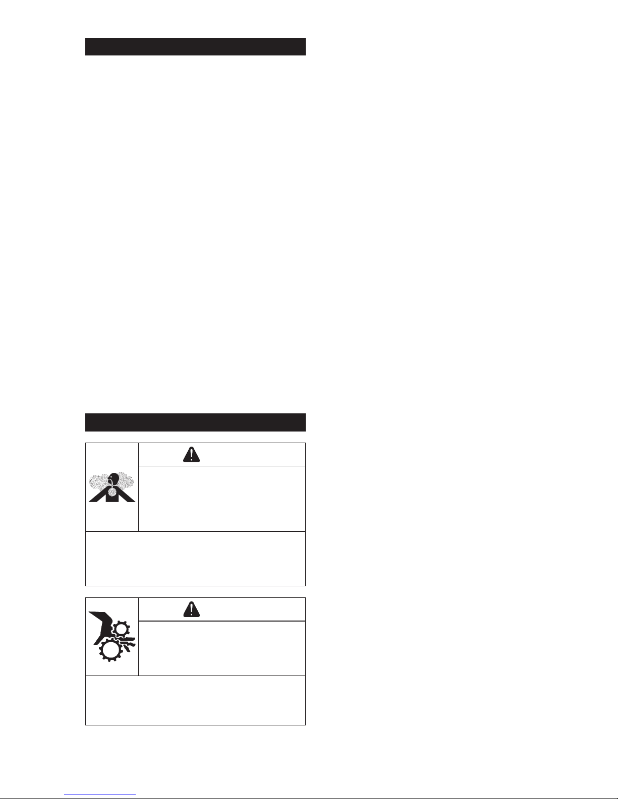
WARNING
Carbon Monoxide. Can cause
severe nausea, fainting or death.
Avoid inhaling exhaust fumes.
Only use product outdoors.
Engine exhaust gases contain poisonous carbon
monoxide.
Carbon monoxide is odorless, colorless, and can
cause death if inhaled.
Page 3
3
35 590 01 Rev. C
KohlerPower.com
EN
S
V
W
T
T
U
O
N
O
P
Q
R
H
B
D
E
C
A
H
B
A
E
D
G
F
C
J
K L
I
M
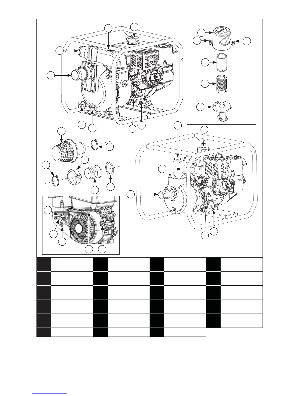
A
Pump Suction
Port
B
Pump
Discharge Port
C
Oil Fill Plug/
Dipstick
D Fuel Cap
E Pump Filler Cap F Knob Nut G
Pump Drain
Plug
H Oil Drain Plug
I Fuel Shut-Off J Choke Lever K Throttle Lever L
On/Off Switch
(if equipped)
M
Recoil Starter
Handle
N
Air Cleaner
Cover
O Bail P Precleaner
Q Paper Element R
Air Cleaner
Base
S Suction Strainer T Clamp
U Coupling V Rubber Seal W Hose Joint
Page 4
4 35 590 01 Rev. CKohlerPower.com
Pre-Start Checklist
1. Ensure pump is at least 3.3 ft. (1 m) from
building or other equipment.
2. Place pump on a fl at sturdy surface. Select a
clean location, ventilated and protected from
inclement weather. Select a location which
will not impede movement of people or
vehicles.
3. Make sure pump remains stable and
immobile while in operation. Do not forget
that suction hose tends to pull pump towards
water source during pumping.
4. Place pump as close as possible to liquid
being drawn in. A shorter vertical distance
between pump and liquid surface will yield
more rapid priming and greater volume of
liquid pumped. If pump is operated beside a
pit or body of water, be sure it is well
anchored so it does not fall in.
5. Submerge suction strainer (S) completely
within liquid, taking care that it is not blocked.
6. Refer to all warning labels prior to starting.
7. Check oil level. Add oil if low. Do not overfi ll.
8. Check fuel level. Add fuel if low. Check fuel
system components and lines for leaks.
Never refuel while unit is running.
9. Check that air cleaner components and all air
inlets are unobstructed, equipment covers,
and guards are in place and securely
fastened.
Starting
WARNING
Carbon Monoxide. Can cause
severe nausea, fainting or
death.
Avoid inhaling exhaust fumes.
Only use product outdoors.
Engine exhaust gases contain poisonous
carbon monoxide.
Carbon monoxide is odorless, colorless, and
can cause death if inhaled.
WARNING
Rotating Parts can cause severe
injury.
Stay away while pump is in
operation.
Keep hands, feet, hair, and clothing away
from all moving parts to prevent injury. Never
operate pump with covers, shrouds, or
guards removed.
NOTE: Never attempt to operate pump without
priming water or pump will overheat.
Extended dry operation will destroy
mechanical seal.
If unit has been operated dry, stop
engine immediately and allow pump to
cool before adding priming water.
NOTE: Always use a suction strainer (S) with
suction hose. Gravel or debris sucked
into pump will cause serious damage
to impeller and pump casting.
NOTE: Pump is not designed for on-board
use. Do not use it while installed on a
vehicle.
Do not leave pump inside vehicle or in
trunk.
When operating or transporting pump,
be sure it is kept upright. If it tilts, fuel
may leak from fuel tank.
1. Immerse suction strainer (S) completely in
liquid that is to be sucked up. If there is a risk
that it could become blocked up, then place
suction strainer (S) on a stone base.
2. Fill body of pump with water via pump
discharge port (B) or through pump fi ller cap
(E).
3. Connect two discharge and suction couplings
(U).
4. Turn fuel shut-off (I) valve to ON position (if
equipped).
5. Turn engine on/off switch (L) to ON position
(if equipped).
6. Start engine as follows:
Cold engine: Place throttle lever (K) midway
between SLOW and FAST positions. Place
choke lever (J) into ON position.
Warm engine: Place throttle lever (K) midway
between SLOW and FAST positions. Return
choke lever (J) to OFF position as soon as
engine starts. A warm engine usually does
not require choke on.
7. Slowly pull recoil starter handle (M) until just
past compression-STOP! Return recoil
starter handle (M); fi rmly pull straight out to
avoid excessive rope wear from starter rope
guide.
8. Gradually return choke lever (J) to OFF
position after engine starts and warms up.
Engine/equipment may be operated during
warm up period, but it may be necessary to
leave choke lever (J) partially on until engine
warms up.
Page 5
5
35 590 01 Rev. C
KohlerPower.com
EN
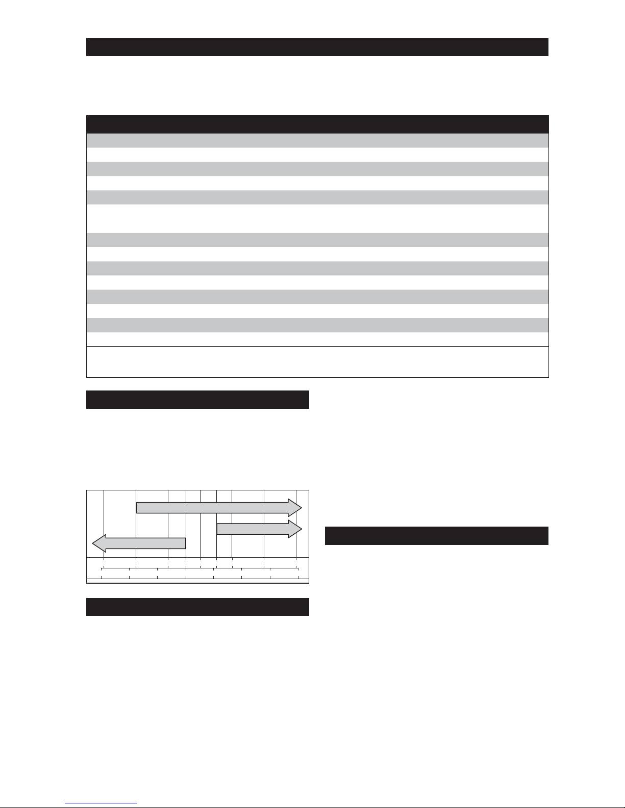
Cold Weather Starting
NOTE: Ensure water in pump body is not
frozen before starting.
When starting pump in low ambient
temperatures, allow engine to idle before
increasing fl ow of liquid. Follow chart for
temperature and time.
< -4° F (< -20° C) 5 minutes
-4° to 14° F (-20° to -10° C) 2 minutes
14° to 23° F (-10° to -5° C) 1 minutes
> 41° F (> 5° C) 20 seconds
1. Use proper oil for temperature expected.
2. Use fresh winter grade fuel. Winter grade
fuel has higher volatility to improve starting.
Operation
WARNING
Rotating Parts can cause severe
injury.
Stay away while pump is in
operation.
Keep hands, feet, hair, and clothing away
from all moving parts to prevent injury. Never
operate pump with covers, shrouds, or
guards removed.
NOTE: If there is no fl ow of liquid through
pump, stop it and check suction circuit
(suction strainer (S) and pipes).
NOTE: Avoid placing any fl ammable materials
near exhaust outlet during operation.
Do not place any material on pump
during operation.
Pump controls fl ow of liquid in accordance with
its running speed. Pump engine is equipped
with a speed control lever that enables fl ow
from pump to be controlled.
Flow from pump also depends on suction and
discharge elevation heads and on quality of
liquid that is being pumped (clean / muddy
water).
1. Move position of speed control lever (MAX to
increase fl ow, MIN to reduce it).
Angle of Operation
Do not operate this engine exceeding maximum
angle of operation; see specifi cation table.
Engine damage could result from insuffi cient
lubrication.
Stopping
1. If equipped, move throttle lever (K) to slow or
idle position; stop engine.
2. Pump stops.
3. If equipped, close fuel shut-off (I) valve.
4. Disconnect suction and discharge pipes and
allow liquid to fl ow out.
5. If pump is not used again on same day, rinse
it out.
Rinsing
After pump has stopped and cooled down.
1. Fill pump body with clean water via pump
discharge port (B) or through pump fi ller cap
(E).
2. Slowly pull on recoil starter handle (M)
several times until resistance is encountered
and then allow it to return gently.
3. Unscrew and remove pump drain plug (G)
from pump and allow water to fl ow out.
4. Screw pump drain plug (G) back into
position.
5. Repeat operation if necessary.
6. Clean suction strainer (S), remove any dirt if
necessary and rinse with clean water.
Engine Speed
NOTE: Do not tamper with governor setting to
increase maximum engine speed.
Overspeed is hazardous and will void
warranty.
High Altitude Operation
This engine may require a high altitude
carburetor kit to ensure correct engine
operation at altitudes above 4000 ft. (1219
meters). To obtain high altitude kit information
or to fi nd a Kohler authorized dealer
KohlerPower.com or call 1-800-544-2444 (U.S.
and Canada).
This engine should be operated in its original
confi guration below 4000 ft. (1219 meters) as
damage may occur if high altitude carburetor kit
is installed and operated below 4000 ft. (1219
meters).
Carburetor Icing
NOTE: Running engine with cover (N)
positioned for cold weather operation
in normal conditions can damage
engine.
Carburetor icing can take place when certain
combinations of temperature and humidity
exist. Result of carburetor icing is rough running
at idle or low speed as well as black or white
smoke.
To reduce likelihood of carburetor icing, air
cleaner cover (N) can be rotated to draw
warmer air from muffl er side. For cold weather
operation, position air cleaner cover (N) with
snowfl ake decal out.
For normal operation, position air cleaner cover
(N) with sun decal out.
Page 6
6 35 590 01 Rev. CKohlerPower.com
Oil Recommendations
We recommend use of Kohler oils for best
performance. Other high-quality detergent
oils (including synthetic) of API (American
Petroleum Institute) service class SJ or higher
are acceptable. Select viscosity based on air
temperature at time of operation as shown in
table below.
°F
-20
020324060
50 80 100
°C
-30 -20
-10 0
10 20 30
40
5W-30
10W-30
SAE 30
Check Oil Level
NOTE: To prevent extensive engine wear or
damage, never run engine with oil level
below or above operating range
indicator on dipstick (C).
Ensure engine is cool. Clean oil fi ll plug/dipstick
(C) areas of any debris.
1. Remove dipstick (C); wipe oil off.
2. Reinsert dipstick (C) into tube; rest on oil fi ll
neck; turn counterclockwise until cap drops
down to lowest point of thread leads; do not
thread cap onto tube.
a. Remove dipstick (C); check oil level.
Level should be at top of indicator on
dipstick (C).
or
b. Remove oil fi ll plug (C). Level should be
up to point of overfl owing fi ller neck.
3. If oil is low, add oil up to point of overfl owing
fi ller neck.
4. Reinstall dipstick (C) or oil fi ll plug (C) and
tighten securely.
Change Oil
Change oil while engine is warm.
1. Clean area around oil fi ll cap/dipstick (C) and
oil drain plug (H).
2. Remove oil drain plug (H) and oil fi ll cap/
dipstick (C). Drain oil completely.
3. Reinstall oil drain plug (H). Torque to 13 ft. lb.
(17.6 N·m).
4. Fill crankcase with new oil, up to point of
overfl owing fi ller neck.
5. Reinstall oil fi ll cap/dipstick (C) and tighten
securely.
6. Dispose of used oil in accordance with local
ordinances.
Maintenance Instructions
All maintenance operations are to be carried out as described in maintenance table. Their
frequency is given for your information, for pumps operating with fuel or oil in accordance with
specifi cations given in this manual.
If pump is used under extreme conditions, reduce interval between maintenance operations.
Maintenance Schedule
After fi rst 5 Hours
● Change oil.
Every 50 Hours or Annually
● Service/replace precleaner (P).
Every 100 Hours or Annually
1
● Change oil.
● Clean cooling areas.
Every 200 Hours
2
● Check and adjust valve clearance when engine is cold.
Every 200 Hours
● Replace air cleaner element (Q).
Every 300 Hours
● Check fuel fi lters (tank outlet fi lter and in-line fi lter) and clean or replace if needed (if equipped).
Every 500 Hours or Annually
1
● Replace spark plug and set gap.
1
Perform these procedures more frequently under severe, dusty, dirty conditions.
2
Have a Kohler portable dealer perform this service.
Page 7
7
35 590 01 Rev. C
KohlerPower.com
EN
● Methyl Tertiary Butyl Ether (MTBE) and
unleaded gasoline blend (max 15% MTBE by
volume) are approved.
● Do not add oil to gasoline.
● Do not overfi ll fuel tank.
● Do not use gasoline older than 30 days.
Add Fuel
WARNING
Explosive Fuel can cause fi res
and severe burns.
Do not fi ll fuel tank while engine is
hot or running.
Gasoline is extremely fl ammable and
its vapors can explode if ignited. Store
gasoline only in approved containers, in
well ventilated, unoccupied buildings, away
from sparks or fl ames. Spilled fuel could
ignite if it comes in contact with hot parts or
sparks from ignition. Never use gasoline as a
cleaning agent.
Ensure engine is cool.
1. Clean area around fuel cap (D).
2. Remove fuel cap (D). Fill to base of fi ller
neck. Do not overfi ll fuel tank. Leave room
for fuel to expand.
3. Reinstall fuel cap (D) and tighten securely.
Fuel Line
Low permeation fuel line must be installed on
carbureted Kohler Co. engines to maintain EPA
and CARB regulatory compliance.
Fuel Valve
Engines are equipped with a fuel valve
and integral screen fi lter located at inlet of
carburetor. It controls and fi lters fuel fl ow from
tank to carburetor. Clean fuel valve cup of
debris.
1. Remove two nuts, two screws, and
carburetor cover panel.
2. Turn fuel valve lever to OFF position.
3. Remove fuel valve cup. Remove O-ring and
fi lter screen.
4. Clean screen and fuel valve cup with solvent
and wipe it off.
5. Check screen and O-ring, replace if
damaged.
6. Reinstall O-ring followed by fuel valve cup.
Rotate fuel valve cup until it is fi nger tight.
Turn with a wrench 1/2 to 3/4 full turn.
7. Turn fuel valve to ON position and check for
leaks. If fuel valve leaks repeat steps 5 & 6.
8. Tighten fuel cap (D) securely.
Oil Sentry™ (if equipped)
This switch is designed to prevent engine
from starting in a low oil or no oil condition. Oil
Sentry™ may not shut down a running engine
before damage occurs. In some applications
this switch may activate a warning signal. Read
your equipment manuals for more information.
Assembly of Hoses
Suction:
1. Connect suction strainer (S) to 1 end of
reinforced hose and secure with clamp (T).
2. Insert smaller end of hose joint (W) through
larger end of coupling (U). Connect other end
of hose to hose joint (W) and coupling (U)
and secure with clamp (T).
3. Place rubber seal (V) at end of hose joint
(W), and attach hose joint (W) to pump
suction port (A). Tighten coupling (U).
Discharge:
1. Connect suction strainer (S) to 1 end of hose
and secure with clamp (T).
2. Insert smaller end of hose joint (W) through
larger end of coupling (U). Connect other end
of hose to hose joint (W) and coupling (U)
and secure with clamp (T).
3. Place rubber seal (V) at end of hose joint
(W), and attach hose joint (W) to pump
discharge port (B). Tighten coupling (U).
Fuel Recommendations
WARNING
Explosive Fuel can cause fi res
and severe burns.
Do not fi ll fuel tank while engine is
hot or running.
Gasoline is extremely fl ammable and
its vapors can explode if ignited. Store
gasoline only in approved containers, in
well ventilated, unoccupied buildings, away
from sparks or fl ames. Spilled fuel could
ignite if it comes in contact with hot parts or
sparks from ignition. Never use gasoline as a
cleaning agent.
NOTE: E15, E20 and E85 are NOT approved
and should NOT be used; effects of
old, stale or contaminated fuel are not
warrantable.
Fuel must meet these requirements:
● Clean, fresh, unleaded gasoline.
● Octane rating of 87 (R+M)/2 or higher.
● Research Octane Number (RON) 90 octane
minimum.
● Gasoline up to 10% ethyl alcohol, 90%
unleaded is acceptable.
Page 8

8 35 590 01 Rev. CKohlerPower.com
9. Reinstall carburetor cover panel securing
with hardware removed in step 1.
Spark Plugs
CAUTION
Electrical Shock can cause injury.
Do not touch wires while engine
is running.
Never operate pump in rain or snow.
Never touch pump with wet hands or
electrical shock will occur.
Clean out spark plug recess. Remove plug and
replace.
1. Check gap using wire feeler gauge. Adjust
gap, see specifi cation table for adjustment.
2. Install plug into cylinder head.
3. Torque plug to 20 ft. lb. (27 N·m).
Cleaning Pump
1. Clean pump, especially air inlets and outlets
of engine with a cloth and a brush.
2. Check general condition of pump and
replace defective parts.
Air Cleaner
NOTE: Running engine with cover (N)
positioned for cold weather operation
in normal conditions can damage
engine.
NOTE: Operating engine with loose or
damaged air cleaner components
could cause premature wear and
failure. Replace all bent or damaged
components.
NOTE: Paper element (Q) cannot be blown
out with compressed air.
Move bails (O) on air cleaner cover (N) down;
remove latches from under tabs on base (R);
remove cover (N).
Precleaner:
1. Remove precleaner (P) from paper element
(Q).
2. Replace or wash precleaner (P) in warm
water with detergent. Rinse and allow to air
dry.
3. Lightly oil precleaner (P) with new engine oil;
squeeze out excess oil.
4. Reinstall precleaner (P) over paper element
(Q).
Paper Element:
1. Separate precleaner (P) from element (Q);
service precleaner (P) and replace paper
element (Q).
2. Install new paper element (Q) on base (R);
install precleaner (P) over paper element (Q).
Position air cleaner cover (N) for normal
operation (sun decal out) or cold weather
operation (snowfl ake decal out); place latches
under tabs on base (R); lift up bails (O) to
secure cover (N).
Breather Tube
Ensure both ends of breather tube are properly
connected.
Air Cooling
WARNING
Hot Parts can cause severe
burns.
Do not touch engine while
operating or just after stopping.
Never operate pump with heat shields or
guards removed. Do not modify pump.
Place pump in a place where pedestrians or
children are not likely to touch pump.
Be sure to carry pump only by its carrying
handles.
Proper cooling is essential. To prevent over
heating, clean screens, cooling fi ns, and other
external surfaces of engine. Avoid spraying
water at wiring harness or any electrical
components. See Maintenance Schedule.
Repairs/Service Parts
We recommend that you use a Kohler portable
dealer for all maintenance, service, and
replacement parts for engine. To fi nd a Kohler
portable dealer visit KohlerPower.com or call
1-800-544-2444 (U.S. and Canada).
Transporting Pump
Before transporting pump, check that bolts
are correctly tightened, close fuel valve. Pump
should be transported in its normal operating
position; never lay it on its side. Ensure where
pump is to be stored or used is carefully
prepared beforehand.
Storage
If pump is not used for a long period of time,
storage operations should be carried out as per
instructions below.
NOTE: Never operate pump without fi lling
pump body with water and immersing
suction strainer (S) in water
beforehand.
1. Add Kohler PRO Series fuel treatment or
equivalent to fuel tank. Run engine 2-3
minutes to get stabilized fuel into fuel system
(failures due to untreated fuel are not
warrantable).
Page 9

9
35 590 01 Rev. C
KohlerPower.com
EN
2. Change oil while engine is still warm from
operation. Remove spark plug and pour
about 1 oz. of engine oil into cylinder.
Replace spark plug and crank engine slowly
to distribute oil.
3. Using clean water rinse pump and pipes
thoroughly.
4. Clean outside of pump and apply a rustprevention product to any worn or damaged
areas.
5. Cover pump with a protective cover to
protect it against dust and store it in a clean
and dry place.
Troubleshooting
Do not attempt to service or replace major engine components, or any items that require special
timing or adjustment procedures. This work should be performed by a Kohler portable dealer.
Problem
Possible Cause
Engine Not
Starting
Engine
Stopped
Automatic
Priming Fault
Low Flow
Air cleaner blocked ●●
Fuel level too low ●●
Blocked fuel fi lter ●●
Fuel supply blocked or leaking ●●
Level of liquid being pumped is too
low
●
Water level too low in pump body ●
Intake is blocked ●
Half-couplings not making an airtight
connection
●
Inadequate tightening of pump drain
plug
●
Air in suction circuit ●
Engine speed control lever set to
MIN position
●
Pipe too long or bent ●
Suction side is too high up ●
Pipes leaking ●
Clogging-up of impeller ●
Wearing of impeller ●
Damage to mechanical seal ●
Loss of engine power ●
Page 10

10 35 590 01 Rev. CKohlerPower.com
Specifi cations
Model
TP 3.0 WP 2.0 WP 3.0
Overall Dimensions (L x W x H)
27.0 in. (685 mm)
20.9 in. (530 mm)
21.3 in. (540 mm)
24.3 in. (615 mm)
18.8 in. (476 mm)
19.2 in. (487 mm)
Suction and Discharge Size 3 in. (76 mm) 2 in. (51 mm) 3 in. (76 mm)
Dry Weight 137.0 lbs. (68.5 kg) 66.0 lbs. (29.9 kg) 77.0 lbs. (34.9 kg)
Maximum Flow Rate 317 gal./min.
(1,200 l/min.)
159 gal./min.
(602 l/min.)
265 gal./min.
(1,003 l/min.)
Maximum Suction Head 26 ft. (8 m) 26 ft. (8 m) 26 ft. (8 m)
Maximum Lift Head 85 ft. (26 m) 85 ft. (26 m) 98 ft. (30 m)
Maximum Debris Size 1.1 in. (28 mm) N/A N/A
Engine Specifi cations
Bore
3.1 in. (78 mm) 2.8 in. (70 mm)
Stroke 2.3 in. (58 mm) 2.1 in. (54 mm)
Displacement 16.9 in. (277 cc) 12.7 in. (208 cc)
Oil Capacity (Refi ll) 1.16 U.S. qt. (1.1 L) 0.63 U.S. qt. (0.60 L)
Spark Plug Gap 0.03 in. (0.76 mm)
Maximum Angle of Operation
(@ full oil level)*
25°
Fuel See fuel section
Fuel Tank Capacity 2 gal. (7.4 L) 1 gal. (4.3 L)
*Exceeding maximum angle of operation may cause engine damage from insuffi cient lubrication.
Additional specifi cation information can be found at KohlerPower.com.
Exhaust Emission Control System for models TP 3.0, WP 2.0, WP 3.0 is EM for U.S. EPA,
California, and Europe.
Page 11
11
35 590 01 Rev. C
KohlerPower.com
EN
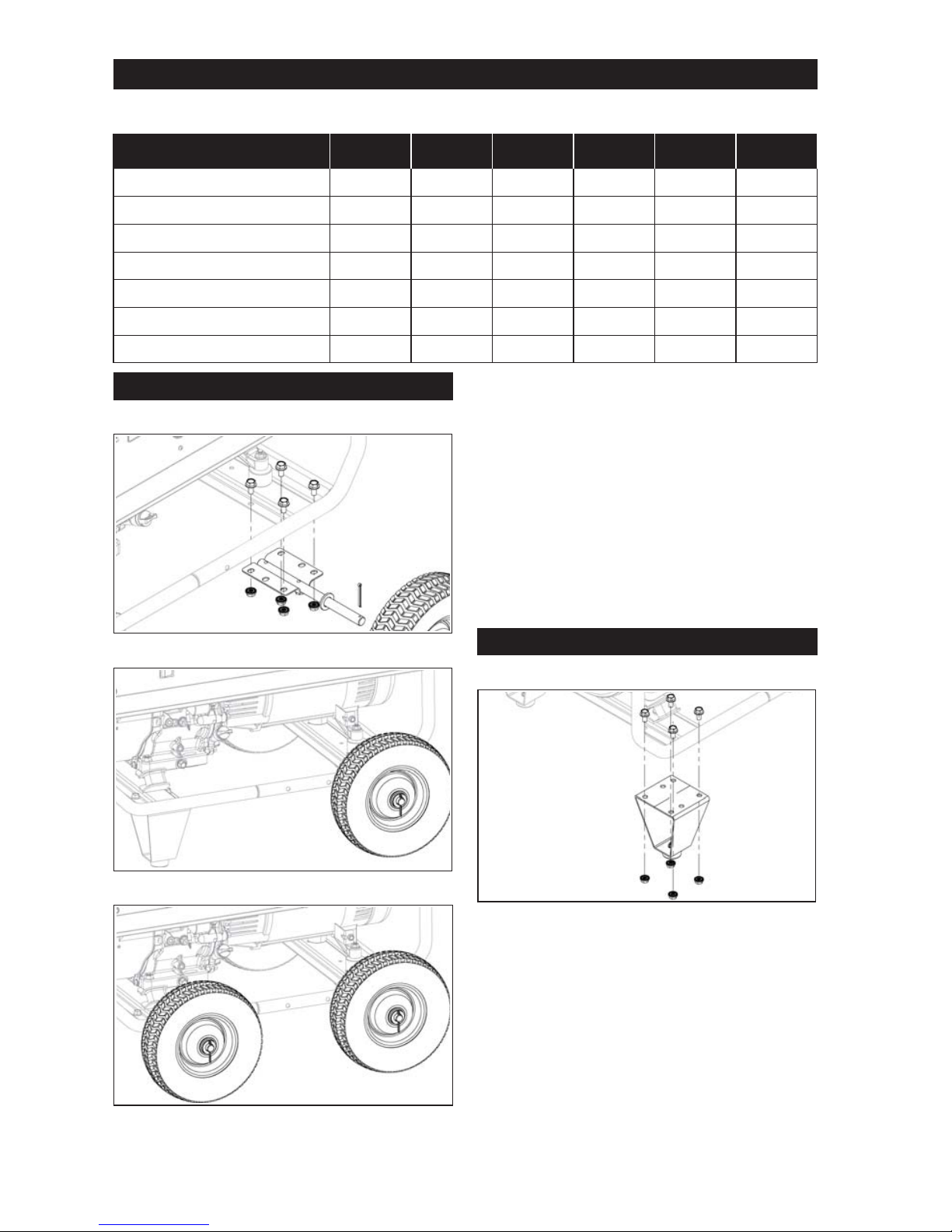
Install Wheel Kit
Wheel Kit
Wheel Kit (Wheels and Legs)
Wheel Kit (4 Wheels)
NOTE: Tilt unit so fuel tank cap is upward to
ensure no fuel leakage.
NOTE: A clamping device or an assistant to
hold assembly while installing kit will
make process easier.
Wheel kit includes 2 wheels and mounting
hardware to be installed opposite of engine
side. Wheel kit and leg kit are designed to
be installed together. 2 wheel kits can be
combined for a 4 wheel confi guration.
1. Place 4 screws into holes of frame.
2. Bring bracket of wheel under frame and align
screws with bracket holes.
3. Thread nuts to screws. Torque to 221 in. lb.
(25 N·m).
Install Leg Kit
Leg Kit
NOTE: Tilt unit so fuel tank cap is upward to
ensure no fuel leakage.
NOTE: A clamping device or an assistant to
hold assembly while installing kit will
make process easier.
Leg kit includes 2 legs and mounting hardware.
Leg kit and wheel kit are designed to be
installed together. 2 leg kits can be combined
for a 4 legged confi guration.
1. Place 4 screws into holes of frame.
2. Bring leg under frame and align screws with
leg holes.
3. Thread nuts to screws. Torque to 221 in. lb.
(25 N·m).
Accessory System
Accessory kits available for models in table below which includes custom kits consisting of legs,
handles, wheels, lifting kits — whatever you want, any way you want it.
Accessory System
PRO 5.2 /
5.2 E
PRO 7.5 /
7.5 E GEN 5.0 WP 2.0 WP 3.0 TP 3.0
Wheel Kit ●●●●●●
Leg Kit ●●●●●●
Lifting Kit ●●●
Wheelbarrow Handle Kit ●●●●●●
Cord Management Kit ●●●●●●
Hand Truck Handle Kit ●●●
Isolator Kit ●●●●●●
Page 12

12 35 590 01 Rev. CKohlerPower.com
Install Wheelbarrow Handle Kit
Wheelbarrow Handle Kit
Wheelbarrow handle kit includes two
wheelbarrow handles and mounting hardware.
1. Align handle with holes on frame.
2. Place washers between handle and frame
while installing screw.
3. Thread nut to screw. Torque to 4 in. lb.
(0.5 N·m).
Install Cord Management Kit
Cord Kit
Cord management kit includes 2 posts and
mounting hardware. Cord management kit can
be installed anywhere on unit on same side, not
across unit.
1. Place post sides together onto frame.
2. Place 3 nuts into holes in 1 side.
3. While holding together, insert screws into
other side and thread into nuts. Torque to
221 in. lb. (25 N·m).
Install Lift Kit
Lifting Kit
NOTE: A clamping device or an assistant to
hold assembly while installing kit will
make process easier.
Lift kit includes lift bar and mounting hardware.
1. Align lift bar holes under holes of frame.
2. While holding in this position, install screws.
3. Thread nuts to screws. Torque to 221 in. lb.
(25 N·m).
Install Hand Truck Handle Kit
Hand Truck Handle Kit
NOTE: A clamping device or an assistant to
hold assembly while installing kit will
make process easier.
Hand truck handle kit includes hand truck
handle and mounting hardware.
1. Position hand truck handle on unit aligning
frame holes and handle holes.
2. Place washer between handle and frame.
3. While holding in this position, install screws.
4. Thread nuts to screws. Torque to 4 in. lb.
(0.5 N·m).
5. Install release knob through frame. Place
washer and hitch pin on inside of assembly.
Install Isolator Kit
Isolator Kit
Isolator Kit includes 4 isolators and mounting
hardware.
1. Align isolator holes under holes of frame.
2. While holding in this position, install screws.
3. Thread nuts to screws. Torque to 221 in. lb.
(25 N·m).
Page 13

13
35 590 01 Rev. C
KohlerPower.com
ESS
TP 3.0, WP 2.0, WP 3.0
Manual del propietario de la bomba
de residuos y de la bomba de agua
IMPORTANTE: Lea atentamente todas las instrucciones y precauciones de seguridad
antes de poner el equipo en funcionamiento.
Asegúrese de que la unidad está parada y nivelada antes de realizar
tareas de mantenimiento o reparación.
Registre la información del producto con el fi n de consultarla para realizar pedidos de piezas o para obtener la
cobertura de la garantía.
Especifi cación
Número de serie
Fecha de compra
Page 14

14 35 590 01 Rev. CKohlerPower.com
Advertencia: la Propuesta 65 de California
El escape de motor de este producto contiene sustancias químicas
identifi cadas por el Estado de California como causantes de cáncer,
defectos de nacimiento u otros daños genéticos.
Advertencia: la Propuesta 65 de California
Este producto contiene sustancias químicas identifi cadas por el Estado
de California como causantes de cáncer, defectos de nacimiento u
otros daños genéticos.
ADVERTENCIA
La explosión del
carburante puede
provocar incendios
y quemaduras
graves.
No llene el tanque
de combustible
con el motor en
funcionamiento o
caliente.
La gasolina es muy infl amable
y sus vapores pueden hacer
explosión si se infl aman.
No reposte nunca mientras
fuma ni cerca de una llama
al descubierto. Almacene
la gasolina siempre en
contenedores homologados,
en locales desocupados, bien
ventilados y lejos de chispas
o llamas. El combustible
derramado podría infl amarse
si entra en contacto con las
piezas calientes del motor o las
chispas de encendido. No utilice
nunca gasolina como agente de
limpieza.
ADVERTENCIA
Las piezas
calientes
pueden causar
quemaduras
graves.
No toque el
motor durante el
funcionamiento o
inmediatamente
después de
pararse.
No ponga nunca la bomba
en funcionamiento con
las protecciones térmicas
desmontadas. No modifi que la
bomba.
Coloque la bomba en un lugar
donde no la vayan a tocar los
peatones ni los niños.
Asegúrese de transportar
la bomba por sus asas de
transporte únicamente.
ADVERTENCIA
Las piezas
rotatorias pueden
causar lesiones
graves.
Manténgase
alejado de
la bomba
cuando esté en
funcionamiento.
Para evitar lesiones, mantenga
las manos, los pies, el pelo y la
ropa alejados de las piezas en
movimiento. No ponga nunca la
bomba en funcionamiento con
las cubiertas, revestimientos
térmicos o protecciones
desmontados.
PRECAUCIÓN
Las descargas
eléctricas pueden
provocar lesiones.
No toque los
cables con
el motor en
funcionamiento.
No utilice nunca la bomba bajo
la lluvia o la nieve.
No toque nunca la bomba con
las manos mojadas, ya que
se produciría una descarga
eléctrica.
Precauciones de seguridad
ADVERTENCIA: Un peligro que podría provocar la muerte, lesiones graves o daños materiales considerables.
PRECAUCIÓN: Un peligro que podría provocar lesiones personales o daños materiales de poca gravedad.
NOTA: Se utiliza para notifi car al personal sobre información importante para la instalación, el funcionamiento
o el mantenimiento.
Lea este manual con atención antes de utilizar esta máquina. Este manual deberá acompañar a la máquina en
caso de que esta se venda.
Etiqueta importante en la bomba
WARNING
Carbon Monoxide. Can cause
severe nausea, fainting or death.
Avoid inhaling exhaust fumes.
Only use product outdoors.
Engine exhaust gases contain poisonous carbon
monoxide.
Carbon monoxide is odorless, colorless, and can
cause death if inhaled.
Page 15

15
35 590 01 Rev. C
KohlerPower.com
ESS
S
V
W
T
T
U
O
N
O
P
Q
R
H
B
D
E
C
A
H
B
A
E
D
G
F
C
J
K L
I
M
A
Puerto de succión
de la bomba
B
Puerto de
descarga de
la bomba
C
Tapón de llenado
de aceite con
varilla
D
Tapón de
combustible
E
Tapón del
depósito de
la bomba
F Tuerca de botón G
Tapón de drenaje
de la bomba
H
Tapón de drenaje
del aceite
I
Corte de
combustible
J
Palanca del
estrangulador
K
Palanca del
acelerador
L
Interruptor
de encendido/
apagado
(si está incluido)
M
Manivela
del motor de
arranque de
retroceso
N
Tapa del fi ltro
de aire
O Fiador P Prefi ltro
Q Filtro de papel R
Soporte del fi ltro
de aire
S Filtro de succión T Abrazadera
U Acople V Sello de goma W Junta del tubo
Page 16

16 35 590 01 Rev. CKohlerPower.com
Lista de control previa al arranque
1. Asegúrese de que la bomba se encuentre por lo
menos a 1 m (3.3 pies) de distancia de otro equipo.
2. Coloque la bomba en una superfi cie lisa y fuerte.
Seleccione un lugar limpio, ventilado y protegido de
las inclemencias del tiempo. Seleccione un lugar
que no impida el movimiento de las personas ni los
vehículos.
3. Asegúrese de que la bomba permanezca estable y
no se mueva durante la operación. No olvide que la
manguera de succión tiende a jalar la bomba hacia
la fuente del agua durante el bombeo.
4. Coloque la bomba lo más cerca posible al líquido
que va a absorber. Una distancia vertical más corta
entre la bomba y la superfi cie del líquido producirá
un cebado más rápido y un volumen más grande
de líquido bombeado. Si opera la bomba a un lado
de un foso o caudal de agua, asegúrese de que
esté bien anclada de manera que no caiga adentro.
5. Sumerja el fi ltro de succión (S) completamente
dentro del líquido, teniendo cuidado de que no esté
bloqueado.
6. Consulte todas las etiquetas de advertencia antes
de poner en marcha.
7. Comprobar el nivel de aceite. Añada aceite si está
bajo. No rellene por encima del límite.
8. Compruebe el nivel de combustible. Añada
combustible si está bajo. Compruebe si los
componentes y las tuberías del sistema de
combustible presentan alguna fuga. No reposte
nunca con la unidad en funcionamiento.
9. Verifi que que los componentes del fi ltro de aire y
todas las entradas de aire están libres de
obstrucciones, y que las cubiertas y protecciones
del equipo están en su sitio y bien sujetas.
Arranque
ADVERTENCIA
El monóxido de carbono puede
causar náuseas graves, desmayo
o la muerte. Evite inhalar el humo
de escape. Utilice el producto
únicamente al aire libre.
ADVERTENCIA
Las piezas rotatorias pueden causar
lesiones graves.
Manténgase alejado de la bomba
cuando esté en funcionamiento.
Para evitar lesiones, mantenga las manos, los
pies, el pelo y la ropa alejados de las piezas
en movimiento. No ponga nunca la bomba en
funcionamiento con las cubiertas, revestimientos
térmicos o protecciones desmontados.
NOTA: Nunca intente operar la bomba sin el agua
de cebado o la bomba se calentará. La
operación de secado por periodos largos
destruirá el sello mecánico.
Si la unidad operó en seco, pare el motor
inmediatamente y permita que la bomba se
enfríe antes de añadir el agua de cebado.
NOTA: Siempre use un fi ltro de succión (S) con
manguera de succión. La grava o los
desechos que absorba la bomba causarán
un daño grave al rotor y al armazón de la
bomba.
NOTA: La bomba no está diseñada para uso a
bordo. No la use mientras se encuentre
instalada en un vehículo.
No deje la bomba adentro de un vehículo ni
en la cajuela.
Cuando opere o transporte la bomba,
asegúrese de mantenerla recta. Si se
inclina, se puede fugar combustible del
tanque.
1. Sumerja completamente el fi ltro de succión (S) en
el líquido que se va a aspirar. Si existe el riesgo de
que se vaya a bloquear, entonces ponga el fi ltro de
succión (S) en una base de piedra.
2. Llene el cuerpo de la bomba con agua mediante el
puerto de descarga (B) o a través de la tapa del
tanque (E).
3. Conecte dos acoples de descarga y de succión (U).
4. Gire la válvula de corte de combustible (I) a la
posición ON (si está incluida).
5. Gire el interruptor de encendido/apagado del
motor (L) a la posición ON (si está incluido).
6. Arranque el motor como se indica a continuación:
Motor frío: Ajuste la palanca del acelerador (K) en
la posición intermedia entre SLOW (lento) y FAST
(rápido). Ponga la palanca del estrangulador (J) en
la posición ON.
Motor caliente: Ajuste la palanca del acelerador (K)
en la posición intermedia entre SLOW (lento) y
FAST (rápido). Vuelva a poner la palanca del
estrangulador (J) en la posición OFF tan pronto
como arranque el motor. Normalmente, un motor
caliente no requiere que el estrangulador esté
encendido.
7. Lentamente tire hacia fuera de la manivela del
motor de arranque de retroceso (M) justo hasta
después de la compresión; ¡PARE! Vuelva a la
manivela del motor de arranque de retroceso (M),
tire de ella hacia fuera con fuerza para evitar el
excesivo desgaste del cable de la guía de cable
de arranque.
8. Cuando el motor haya arrancado y se haya
calentado, vuelva a colocar progresivamente la
palanca del estrangulador (J) en la posición OFF.
Durante el periodo de calentamiento se podrá
trabajar con el motor o equipo, pero será necesario
dejar la palanca del estrangulador (J) parcialmente
activada.
Page 17

17
35 590 01 Rev. C
KohlerPower.com
ESS
Arranque en tiempo frío
NOTA: Asegúrese de que el agua que está en el
cuerpo de la bomba no esté congelada
antes de arrancar.
Cuando arranque la bomba en temperaturas bajas,
permita que el motor funcione al ralentí antes de
incrementar el fl ujo del líquido. Siga la tabla para
temperatura y tiempo.
< -20° C (< -4° F) 5 minutos
-20° a -10° C (-4° a 14° F) 2 minutos
-10° a -5° C (14° a 23° F) 1 minutos
> 5° C (> 41° F) 20 segundos
1. Utilice el aceite apropiado para la temperatura
prevista.
2. Use combustible de grado invierno reciente. El
combustible de grado invierno tiene una mayor
volatilidad que mejora el arranque.
Funcionamiento
ADVERTENCIA
Las piezas rotatorias pueden causar
lesiones graves.
Manténgase alejado de la bomba
cuando esté en funcionamiento.
Para evitar lesiones, mantenga las manos, los
pies, el pelo y la ropa alejados de las piezas
en movimiento. No ponga nunca la bomba en
funcionamiento con las cubiertas, revestimientos
térmicos o protecciones desmontados.
NOTA: Si no hay fl ujo o líquido a través de la
bomba, párela y revise el circuito de succión
(fi ltro de succión (S) y tubería).
NOTA: Evite colocar cualquier material infl amable
junta a la salida del escape durante la
operación.
No coloque ningún material sobre la bomba
durante la operación.
La bomba controla el fl ujo de líquido de acuerdo con
su velocidad de ejecución. El motor de la bomba está
equipado con una palanca de control de velocidad
que permite controlar el fl ujo de la bomba.
El fl ujo de la bomba depende también de la succión
y los cabezales de elevación de descarga y de la
calidad del líquido que se va a bombear (agua limpia/
fangosa).
1. Mueva la posición de la palanca de control de
velocidad (MAX para incrementar el fl ujo, MIN
para reducirlo).
Ángulo de funcionamiento
No haga funcionar el motor si supera el ángulo
máximo de funcionamiento, consulte la tabla de
especifi caciones. El motor puede dañarse como
resultado de una lubricación insufi ciente.
Parada
1. Mueva la palanca del acelerador (K), si está
incluida, a la posición “slow” (lento) o “idle” (ralentí);
pare el motor.
2. La bomba se para.
3. Cierre la válvula de corte de combustible (I), si está
incluida.
4. Desconecte los tubos de succión y descarga y
permita que el líquido fl uya hacia afuera.
5. Si no va a usar la bomba de nuevo ese día,
enjuáguela.
Enjuague
Después que la bomba se haya parado y enfriado.
1. Llene el cuerpo de la bomba con agua limpia
mediante el puerto de descarga (B) o a través de la
tapa del tanque (E).
2. Jale lentamente la manivela del motor de arranque
de retroceso (M) varias veces hasta encontrar
resistencia, después permítale regresar
suavemente.
3. Desatornille y quite el tapón de drenaje (G) de la
bomba y permita que el agua fl uya hacia afuera.
4. Atornille el tapón de drenaje de la bomba (G) en su
posición.
5. Repita la operación de ser necesario.
6. Limpie el fi ltro de succión (S), quite cualquier
basura que haya de ser necesario y enjuague
completamente con agua limpia.
Velocidad del motor
NOTA: No altere los ajustes del regulador para
aumentar la velocidad máxima del motor.
El exceso de velocidad es peligroso y
anulará la garantía.
Funcionamiento a gran altitud
Este motor puede requerir un kit de carburador
de gran altitud para garantizar un funcionamiento
correcto del motor a altitudes superiores a
1.219 metros (4.000 pies). Para obtener información
sobre el kit de gran altitud o encontrar a un distribuidor
autorizado de Kohler, consulte KohlerPower.com o
llame a 1-800-544-2444 (EE.UU. y Canadá).
Este motor debe ponerse en funcionamiento en su
confi guración original por debajo de los 1.219 metros
(4.000 pies), pues pueden producirse daños si se
instala y pone en funcionamiento el kit de carburador
de gran altitud por debajo de los 1.219 metros
(4.000 pies).
Formación de hielo en el carburador
NOTA: Si en condiciones normales pone el motor en
funcionamiento con la tapa (N) posicionada
en funcionamiento en clima frío, puede
dañar el motor.
La formación de hielo en el carburador se produce
ante determinadas combinaciones de temperatura y
humedad. El resultado de la formación de hielo en el
carburador es un funcionamiento irregular a velocidad
de ralentí o lenta, así como humo negro.
Para reducir la probabilidad de que se forme hielo
en el carburador, se puede girar la tapa del fi ltro de
aire (N) para obtener aire más caliente del lado del
silenciador. Para el funcionamiento en clima frío,
coloque la tapa del fi ltro de aire (N) con la etiqueta de
copo de nieve por fuera.
Para el funcionamiento normal, coloque la tapa del
fi ltro de aire (N) con la etiqueta de sol por fuera.
Page 18

18 35 590 01 Rev. CKohlerPower.com
Recomendaciones de lubricante
Recomendamos el uso de un aceite de Kohler para
obtener un mejor rendimiento. También se puede
utilizar otro aceite detergente de alta calidad API
(American Petroleum Institute) SJ o superior, incluidos
los aceites sintéticos. Seleccione la viscosidad
en función de la temperatura del aire durante el
funcionamiento como se muestra en la tabla que
aparece a continuación.
°F
-20
020324060
50 80 100
°C
-30 -20
-10 0
10 20 30
40
5W-30
10W-30
SAE 30
Comprobación del nivel de aceite
NOTA: Para evitar las averías y el desgaste
excesivo del motor, nunca ponga el motor
en funcionamiento con un nivel de aceite
inferior o superior al indicador de nivel de
funcionamiento de la varilla (C).
Asegúrese de que el motor esté frío. Limpie los
residuos de las áreas de la varilla de nivel/tapón
de llenado de aceite (C).
1. Extraiga la varilla de nivel (C); limpie el exceso
de aceite.
2. Vuelva a introducir la varilla de nivel (C) en el tubo,
asiéntela en el cuello de llenado de aceite, gírela
en sentido contrario a las agujas del reloj hasta
introducir toda la rosca del tapón de llenado. No
enrosque el tapón en el tubo.
Instrucciones de mantenimiento
Todas las operaciones de mantenimiento se realizarán según lo descrito en la tabla de mantenimiento. Su
frecuencia se da para su información, para las bombas que operan con combustible o aceite de acuerdo con las
especifi caciones que se dan en este manual.
Si la bomba se usa bajo condiciones extremas, disminuya el intervalo entre operaciones de mantenimiento.
Programa de mantenimiento
Después de las 5 primeras horas
● Cambie el aceite.
Una vez al año o cada 50 horas
● Limpie/cambie el prefiltro (P).
Una vez al año o cada 100 horas
1
● Cambie el aceite.
● Limpie las zonas de refrigeración.
Cada 200 horas
2
● Compruebe y ajuste el juego de las válvulas con el motor frío.
Cada 200 horas
● Cambie el elemento del fi ltro de aire (Q).
Cada 300 horas
● Verifi que los fi ltros de combustible (fi ltro de salida del tanque y fi ltro en línea) y límpielos o cámbielos si es
necesario (si están incluidos).
Una vez al año o cada 500 horas
1
● Cambie la bujía y ajuste la separación entre electrodos.
1
Estas operaciones de mantenimiento deberán ejecutarse con mayor frecuencia en ambientes muy
polvorientos o sucios.
2
Pida a un distribuidor móvil de Kohler que realice esta operación.
a. Saque la varilla (C) y compruebe el nivel de
aceite. El nivel debe situarse en la parte
superior de la varilla de nivel (C).
o
b. Extraiga el tapón de llenado (C). El nivel debe
alcanzar el punto de desbordamiento del
cuello de llenado.
3. Si el nivel de aceite es más bajo, añada aceite
hasta el punto de desbordamiento del cuello de
llenado.
4. Vuelva a colocar la varilla de nivel (C) o el tapón de
llenado (C) y apriete fi rmemente.
Cambio del aceite
Cambie el aceite con el motor caliente.
1. Limpie el área que rodea el tapón de llenado de
aceite/varilla (C) y el tapón de drenaje (H).
2. Quite el tapón de drenaje (H) y el tapón de llenado
con varilla (C). Drene el aceite por completo.
3. Vuelva a instalar el tapón de drenaje del aceite (H).
Apriételo a 17,6 Nm (13 ft lb).
4. Llene de aceite nuevo el cárter hasta el punto de
desbordamiento del cuello de llenado.
5. Vuelva a colocar el tapón de llenado con varilla (C)
y apriete fi rmemente.
6. Deseche el aceite usado en conformidad con las
normativas locales.
Page 19

19
35 590 01 Rev. C
KohlerPower.com
ESS
● No añada aceite a la gasolina.
● No llene el tanque de combustible por encima del
límite.
● No utilice gasolina con más de 30 días de
antigüedad.
Añadir Combustible
ADVERTENCIA
La explosión del carburante puede
provocar incendios y quemaduras
graves.
No llene el tanque de combustible con
el motor en funcionamiento o caliente.
La gasolina es muy infl amable y sus vapores
pueden hacer explosión si se infl aman. Almacene
la gasolina siempre en contenedores homologados,
en locales desocupados, bien ventilados y lejos de
chispas o llamas. El combustible derramado podría
infl amarse si entra en contacto con las piezas
calientes del motor o las chispas de encendido. No
utilice nunca gasolina como agente de limpieza.
Asegúrese de que el motor esté frío.
1. Limpie el área que rodea el tapón de combustible (D).
2. Quite el tapón de combustible (D). Llene hasta la
base del cuello de llenado. No llene el tanque de
combustible por encima del límite. Deje espacio
para que se expanda el combustible.
3. Vuelva a instalar el tapón del combustible (D) y
apriete bien.
Tubería de combustible
Debe instalar una tubería de combustible de baja
permeabilidad de motores carburados de Kohler Co.
para respetar las normas EPA y CARB.
Válvula de combustible
Los motores están equipados con una válvula de
combustible y un fi ltro de rejilla integrado situado en
la entrada del carburador. Ésta controla y fi ltra el fl ujo
de combustible del tanque al carburador. Limpie los
residuos de la copa de la válvula de combustible.
1. Extraiga dos tuercas, dos tornillos y la cubierta del
carburador.
2. Gire la palanca de la válvula de combustible a la
posición OFF.
3. Extraiga la copa de la válvula de combustible.
Extraiga la junta tórica y el fi ltro de rejilla.
4. Limpie la rejilla y la copa de la válvula de
combustible con disolvente y limpie el exceso.
5. Compruebe la rejilla y la junta tórica y cámbielas si
están dañadas.
6. Vuelva a instalar la junta tórica seguida de la copa
de la válvula de combustible. Gire con la mano la
copa de la válvula de combustible hasta que quede
bien apretada. Gire de 1/2 a 3/4 de vuelta con una
llave.
7. Gire la válvula de combustible a la posición ON y
compruebe si hay fugas. Si la válvula de
combustible tiene fugas, repita los pasos 5 y 6.
8. Apriete fi rmemente la copa de combustible (D).
9. Vuelva a colocar la cubierta del carburador
fi jándola con los tornillos quitados en el paso 1.
Oil Sentry™ (si está incluido)
Este interruptor está diseñado para evitar que el motor
arranque con poco aceite o ninguno. El Oil Sentry™
no puede apagar un motor en marcha antes de que
se produzca un daño. En algunas aplicaciones este
interruptor puede activar una señal de aviso. Lea los
manuales de su equipo para más información.
Ensamble de los tubos
Succión:
1. Conecte el fi ltro de succión (S) a un extremo del
tubo reforzado y sujete con la abrazadera (T).
2. Introduzca el extremo menor de la junta del tubo
(W) por el extremo mayor del acople (U). Conecte
el otro extremo del tubo a la junta del tubo (W) y al
acople (U) y sujete con la abrazadera (T).
3. Coloque el sello de goma (V) en el extremo de la
junta del tubo (W) y conecte la junta del tubo (W) al
puerto de succión de la bomba (A). Apriete el
acople (U).
Descarga:
1. Conecte el fi ltro de succión (S) a un extremo del
tubo y sujete con la abrazadera (T).
2. Introduzca el extremo menor de la junta del tubo
(W) por el extremo mayor del acople (U). Conecte
el otro extremo del tubo a la junta del tubo (W) y al
acople (U) y sujete con la abrazadera (T).
3. Coloque el sello de goma (V) en el extremo de la
junta del tubo (W) y conecte la junta del tubo (W) al
puerto de descarga de la bomba (B). Apriete el
acople (U).
Recomendaciones de combustible
ADVERTENCIA
La explosión del carburante puede
provocar incendios y quemaduras
graves.
No llene el tanque de combustible con
el motor en funcionamiento o caliente.
La gasolina es muy infl amable y sus vapores
pueden hacer explosión si se infl aman. Almacene
la gasolina siempre en contenedores homologados,
en locales desocupados, bien ventilados y lejos de
chispas o llamas. El combustible derramado podría
infl amarse si entra en contacto con las piezas
calientes del motor o las chispas de encendido.
No utilice nunca gasolina como agente de limpieza.
NOTA: E15, E20 y E85 are NO están autorizados y
NO deben utilizarse; la garantía no cubre los
efectos producidos por el uso de
combustible antiguo, pasado o contaminado.
El combustible debe cumplir con los siguientes
requisitos:
● Gasolina limpia, fresca y sin plomo.
● Octanaje de 87 (R+M)/2 o superior.
● El “Research Octane Number” (RON), deberá ser
de 90 octanos como mínimo.
● Se autoriza el empleo de gasolina de hasta un
volumen máximo del 10% de alcohol etílico y el
90% sin plomo.
● Se autorizan las mezclas de metil-ter-butil-éter
(MTBE) y gasolina sin plomo (hasta un máximo
del 15% de MTBE en volumen).
Page 20

20 35 590 01 Rev. CKohlerPower.com
Bujías
PRECAUCIÓN
Las descargas eléctricas pueden
provocar lesiones.
No toque los cables con el motor en
funcionamiento.
No utilice nunca la bomba bajo la lluvia o la nieve.
No toque nunca la bomba con las manos mojadas,
ya que se produciría una descarga eléctrica.
Limpie el rebaje de la bujía. Extraiga la bujía y
sustitúyala.
1. Compruebe la separación de electrodos con una
galga de espesores. Para ajustar la separación,
consulte la tabla de especifi caciones de ajuste.
2. Coloque la bujía en el cabezal del cilindro.
3. Apriete la bujía a 27 Nm (20 ft lb).
Para limpiar la bomba
1. Limpie la bomba, especialmente las entradas y las
salidas de aire del motor con un trapo y un cepillo.
2. Revise las condiciones generales de la bomba y
reemplace las piezas defectuosas.
Filtro de aire
NOTA: Si en condiciones normales pone el motor
en funcionamiento con la tapa (N)
posicionada en funcionamiento en clima frío,
puede dañar el motor.
NOTA: El funcionamiento del motor con
componentes del fi ltro de aire sueltos o
dañados puede causar daños y desgaste
prematuro. Sustituya todos los componentes
doblados o dañados.
NOTA: El papel fi ltrante (Q) no puede expulsarse
con aire comprimido.
Mueva los fi adores (O) de la tapa del fi ltro de aire (N)
hacia abajo, extraiga las pestañas de la parte inferior
del soporte (R) y extraiga la tapa (N).
Prefi ltro:
1. Extraiga el prefi ltro (P) del papel fi ltrante (Q).
2. Sustituya o lave el prefi ltro (P) con agua templada y
detergente. Aclárelo y déjelo secar al aire.
3. Lubrique ligeramente el prefi ltro (P) con aceite
nuevo y escurra el exceso de aceite.
4. Vuelva a instalar el prefi ltro (P) sobre el papel
fi ltrante (Q).
Elemento de papel:
1. Separe el prefi ltro (P) del elemento fi ltrante (Q),
limpie el prefi ltro (P) y sustituya el elemento
fi ltrante (Q).
2. Instale un nuevo elemento fi ltrante (Q) en la
base (R) e instale el prefi ltro (P) sobre el papel
fi ltrante (Q).
Coloque la tapa del fi ltro de aire (N) para el
funcionamiento normal (etiqueta de sol por fuera) o
el funcionamiento en clima frío (etiqueta de copo de
nieve por fuera), coloque las pestañas en la parte
inferior de la base (R), levante los fi adores (O) para
sujetar la tapa (N).
Tubo del respirador
Asegúrese de que ambos extremos del respirador
están conectados adecuadamente.
Refrigeración por aire
ADVERTENCIA
Las piezas calientes pueden causar
quemaduras graves.
No toque el motor durante el
funcionamiento o inmediatamente
después de pararse.
No ponga nunca la bomba en funcionamiento
con las protecciones térmicas desmontadas.
No modifi que la bomba.
Coloque la bomba en un lugar donde no la vayan a
tocar los peatones ni los niños.
Asegúrese de transportar la bomba por sus asas
de transporte únicamente.
Es esencial una refrigeración adecuada. Para evitar
el sobrecalentamiento, limpie los fi ltros, los álabes
de refrigeración y demás superfi cies externas del
motor. Evite rociar agua al haz de cables o a cualquier
componente eléctrico. Consulte el Programa de
mantenimiento.
Reparaciones/Piezas de recambio
Recomendamos que utilice un distribuidor móvil de
Kohler para el mantenimiento, la reparación o la
sustitución de piezas del motor. Para encontrar un
distribuidor móvil de Kohler, visite KohlerPower.com
o llame al 1-800-544-2444 (EE. UU. y Canadá).
Para transportar la bomba
Antes de transportar la bomba, compruebe que los
tornillos estén bien apretados y cierre la válvula de
combustible. Se debe transportar la bomba en su
posición de funcionamiento normal, nunca la coloque
sobre su costado. Asegúrese de que el lugar donde
guardará y usará la bomba se haya preparado
cuidadosamente con anticipación.
Almacenamiento
Si no usa la bomba por un periodo prolongado, las
operaciones de almacenamiento se deberán realizar
según las siguientes instrucciones.
NOTA: Nunca opere la bomba sin llenar su cuerpo
con agua e sumergir el fi ltro de succión (S)
en agua antes.
1. Añada el tratamiento de combustible Kohler PRO
Series o equivalente al depósito de combustible.
Arranque el motor durante 2-3 minutos para que el
combustible se estabilice en el sistema de
combustible (la garantía no cubre los fallos
provocados por combustible sin tratar).
2. Cambie el aceite con el motor aún caliente. Extraiga
la bujía y vierta aproximadamente 28 g (1 oz) de
aceite de motor en el cilindro. Sustituya la bujía
y arranque el motor lentamente para distribuir
el aceite.
3. Enjuague completamente la bomba y los tubos con
agua limpia.
4. Limpie la parte externa de la bomba y aplique un
producto antioxidante a cualquier área desgastada
o dañada.
Page 21

21
35 590 01 Rev. C
KohlerPower.com
ESS
5. Cubra la bomba con una cubierta protectora para
preservarla del polvo y guárdela en un lugar limpio
y seco.
Localización de averías
No intente reparar o cambiar componentes principales del motor o cualquier elemento que requiera unos
procedimientos de ajuste o sincronización especiales. Este trabajo debe ser realizado por un distribuidor móvil
de Kohler.
Problema
Causa posible
El motor no
arrancará
El motor
se paró
Falla del cebado
automático
Flujo bajo
Filtro de aire bloqueado ●●
Nivel de combustible muy bajo ●●
Filtro de combustible bloqueado ●●
Suministro de combustible bloqueado
o con fuga
●●
El nivel de líquido que se está
bombeando es muy bajo
●
El nivel del agua es muy bajo en el
cuerpo de la bomba
●
La entrada está bloqueada ●
Los semicoples no hacen una conexión
hermética
●
Apretamiento inadecuado del tapón
de drenaje de la bomba
●
Aire en el circuito de succión ●
Palanca de control de velocidad en
la posición MIN
●
Tubo muy largo o doblado ●
Lado de succión muy alto ●
Fuga en la tubería ●
Obstrucción del rotor ●
Desgaste del rotor ●
Daño en el sello mecánico ●
Pérdida de la energía del motor ●
Page 22

22 35 590 01 Rev. CKohlerPower.com
Especifi caciones
Modelo
TP 3.0 WP 2.0 WP 3.0
Dimensiones totales (Largo x
Ancho x Alto)
685 mm (27,0 in)
530 mm (20,9 in)
540 mm (21,3 in)
615 mm (24,3 in)
476 mm (18,8 in)
487 mm (19,2 in)
Succión y tamaño de la descarga 76 mm (3 in) 51 mm (2 in) 76 mm (3 in)
Peso en seco 137.0 lbs. (68,5 kg) 66.0 lbs. (29,9 kg) 77.0 lbs. (34,9 kg)
Caudal máximo 317 gal./min.
(1,200 l/min.)
159 gal./min.
(602 l/min.)
265 gal./min.
(1,003 l/min.)
Succión máxima del cabezal 8 m (26 ft) 8 m (26 ft) 8 m (26 ft)
Elevación máxima del cabezal 26 m (85 ft.) 26 m (85 ft) 30 m (98 ft)
Tamaño máximo de desechos 28 mm (1.1 pul.) N/D N/D
Especifi caciones del motor
Orifi cio
78 mm (3,1 in) 70 mm (2,8 in)
Carrera 58 mm (2,3 in) 54 mm (2,1 in)
Desplazamiento 277 cc (16,9 in) 208 cc (12,7 in)
Capacidad de aceite (rellenado) 1,1 L (1,16 U.S. qt) 0,60 L (0,63 U.S. qt)
Abertura de bujía 0,76 mm (0,03 in)
Ángulo de funcionamiento máximo
(con nivel máximo de aceite)*
25°
Combustible Véase la sección de combustible
Capacidad del tanque de
combustible
7.4 L (2 gal.) 4.3 L (1 gal.)
*Si se excede el ángulo máximo de funcionamiento puede dañarse el motor debido a lubricación insufi ciente.
Puede encontrar información adicional sobre las especifi caciones en KohlerPower.com.
El sistema de control de emisiones de escape para los modelos TP 3.0, WP 2.0, WP 3.0 es EM para la EPA
estadounidense, California y Europa.
Page 23

23
35 590 01 Rev. C
KohlerPower.com
ESS
Instalación del kit de ruedas
Kit de ruedas
Kit de ruedas (ruedas y patas)
Kit de ruedas (4 ruedas)
NOTA: Incline la unidad de manera que el tapón del
tanque de combustible quede hacia arriba
para que no se produzcan fugas de
combustible.
NOTA: Un dispositivo de sujeción o un ayudante
que sujete el conjunto durante la instalación
del kit facilitarán el proceso.
El kit de ruedas incluye 2 ruedas y los elementos
de montaje para su instalación en el lado contrario
al motor. El kit de ruedas y el kit de patas están
diseñados para su instalación juntos. Es posible
combinar 2 kits de ruedas para una confi guración
de 4 ruedas.
1. Introduzca 4 tornillos en los orifi cios del bastidor.
2. Sitúe el soporte de la rueda bajo el bastidor y
alinee los tornillos con los orifi cios del soporte.
3. Enrosque las tuercas en los tornillos. Aplique un
par de apriete de 25 Nm (221 in lb).
Instalación del kit de patas
Kit de patas
NOTA: Incline la unidad de manera que el tapón del
tanque de combustible quede hacia arriba
para que no se produzcan fugas de
combustible.
NOTA: Un dispositivo de sujeción o un ayudante
que sujete el conjunto durante la instalación
del kit facilitarán el proceso.
El kit de patas incluye 2 patas y los elementos de
montaje. El kit de patas y el kit de ruedas están
diseñados para su instalación juntos. Es posible
combinar 2 kits de patas para una confi guración
de 4 patas.
1. Introduzca 4 tornillos en los orifi cios del bastidor.
2. Sitúe la pata bajo el bastidor y alinee los tornillos
con los orifi cios de la pata.
3. Enrosque las tuercas en los tornillos. Aplique un
par de apriete de 25 Nm (221 in lb).
Sistema de accesorios
Kits de accesorios disponibles para los modelos indicados en la tabla siguiente, que incluye kits personalizados
compuestos por patas, brazos, ruedas, kits de elevación... Todo lo que desee, del modo que desee.
Sistema de accesorios
PRO 5.2 /
5.2 E
PRO 7.5 /
7.5 E GEN 5.0 WP 2.0 WP 3.0 TP 3.0
Kit de ruedas ●●●●●●
Kit de patas ●●●●●●
Kit de elevación ●●●
Kit de brazos de carretilla ●●●●●●
Kit de tendido de cables ●●●●●●
Kit de brazos de carro manual ●●●
Kit de aislantes ●●●●●●
Page 24

24 35 590 01 Rev. CKohlerPower.com
Instalación del kit de brazos de carretilla
Kit de brazos de carretilla
El kit de brazos de carretilla incluye dos brazos de
carretilla y los elementos de montaje.
1. Alinee el brazo con los orifi cios del bastidor.
2. Coloque arandelas entre el brazo y el bastidor
cuando instale el tornillo.
3. Enrosque la tuerca en el tornillo. Apriételo a 0,5 Nm
(4 in lb).
Instalación del kit de tendido de cables
Kit de cables
El kit de tendido de cables incluye 2 postes y los
elementos de montaje. El kit de tendido de cables se
puede instalar en cualquier lugar de la unidad en un
mismo lado, no de un lado a otro de la unidad.
1. Coloque los lados de los postes juntos sobre el
bastidor.
2. Coloque 3 tuercas en los orifi cios en 1 lado.
3. Mientras los sujeta juntos, introduzca los tornillos
por el otro lado y enrósquelos en las tuercas.
Aplique un par de apriete de 25 Nm (221 in lb).
Instalación del kit de elevación
Kit de elevación
NOTA: Un dispositivo de sujeción o un ayudante
que sujete el conjunto durante la instalación
del kit facilitarán el proceso.
El kit de elevación incluye una barra de elevación y
los elementos de montaje.
1. Alinee los orifi cios de la barra de elevación bajo los
orifi cios del bastidor.
2. Mientras sujeta en esta posición, instale los tornillos.
3. Enrosque las tuercas en los tornillos. Aplique un
par de apriete de 25 Nm (221 in lb).
Instalación del kit de brazos de carro manual
Kit de brazos de carro manual
NOTA: Un dispositivo de sujeción o un ayudante
que sujete el conjunto durante la instalación
del kit facilitarán el proceso.
El kit de brazos de carro manual incluye el brazo del
carro manual y los elementos de montaje.
1. Sitúe el brazo del carro manual sobre la unidad
alineando los orifi cios del bastidor con los orifi cios
del brazo.
2. Coloque una arandela entre el brazo y el bastidor.
3. Mientras sujeta en esta posición, instale los tornillos.
4. Enrosque las tuercas en los tornillos. Apriételo a
0,5 Nm (4 in lb).
5. Instale la rueda de liberación a través del bastidor.
Coloque la arandela y el pasador en el interior del
conjunto.
Instalación del kit de aislantes
Kit de aislantes
El kit de aislantes incluye 4 aislantes y los elementos
de montaje.
1. Alinee los orifi cios del aislante bajo los orifi cios del
bastidor.
2. Mientras sujeta en esta posición, instale los tornillos.
3. Enrosque las tuercas en los tornillos. Aplique un
par de apriete de 25 Nm (221 in lb).
Page 25

25
35 590 01 Rév. C
KohlerPower.com
FRC
TP 3.0, WP 2.0, WP 3.0
Manuel du propriétaire - Pompe à résidus et
pompe à eau
IMPORTANT : Lisez toutes les consignes et précautions de sécurité avant
d'utiliser le matériel.
Le moteur doit être arrêté et de niveau avant d'exécuter tout
travail de maintenance ou d'entretien.
Enregistrez les informations concernant le produit pour référence lors de la commande de pièces ou de
demande de couverture de garantie.
Spécifi cations
Numéro de série
Date d'achat :
Page 26

26 35 590 01 Rév. CKohlerPower.com
AVERTISSEMENT
Les pièces
tournantes
peuvent causer
de graves
blessures.
Tenez-vous
éloigné de
la pompe
pendant qu'elle
fonctionne.
Tenez vos mains, pieds,
cheveux et vêtements à l’écart
de toutes les pièces mobiles
pour prévenir les blessures.
Ne faites jamais fonctionner la
pompe si des couvercles, des
enveloppes ou des protections
ont été enlevés.
AVERTISSEMENT
Carburant
explosif pouvant
causer des
incendies et des
brûlures graves.
N'ajoutez pas de
carburant si le
moteur est chaud
ou s'il tourne.
L’essence est extrêmement
infl ammable et le contact de
ses vapeurs avec une source
d’allumage peut provoquer une
explosion. Ne faites jamais
le plein en fumant ou à côté
d'une fl amme. Entreposez
l'essence dans des récipients
approuvés et dans des
bâtiments non occupés, à
l'abri des étincelles ou des
fl ammes. Des éclaboussures de
carburant peuvent s'enfl ammer
au contact de pièces chaudes
ou d'étincelles provenant de
l'allumage. N’utilisez jamais
d’essence comme agent
nettoyant.
AVERTISSEMENT
Les pièces
chaudes peuvent
causer de graves
brûlures.
Ne touchez
pas au moteur
pendant qu’il
tourne ou si vous
venez tout juste
de l'arrêter.
Ne faites jamais fonctionner
la pompe si des écrans
thermiques ou des
protections ont été enlevés.
Ne modifi ez pas la pompe.
La pompe doit être installée
dans un endroit inaccessible
par les piétons ou les enfants.
La pompe ne doit être portée
que par les poignées.
ATTENTION
Les chocs
électriques
peuvent causer
des blessures.
Ne touchez pas
aux fi ls pendant
que le moteur
tourne.
Ne laissez jamais tourner la
pompe sous la pluie ou la
neige.
Ne touchez jamais la pompe
avec les mains mouillées. Il y
a risque de choc électrique.
Consignes de sécurité
AVERTISSEMENT : Un danger pouvant entraîner la mort, de graves blessures ou des dommages
matériels.
ATTENTION : Un danger pouvant entraîner des blessures légères ou des dommages matériels.
REMARQUE : Cette mention est utilisée pour attirer l'attention sur des détails importants concernant
l'installation, l'utilisation ou l'entretien.
Lisez ce manuel avec précaution avant d'utiliser cette machine. Ce manuel doit rester avec la machine si
celle si est vendue.
Étiquette importante sur la pompe
WARNING
Carbon Monoxide. Can cause
severe nausea, fainting or death.
Avoid inhaling exhaust fumes.
Only use product outdoors.
Engine exhaust gases contain poisonous carbon
monoxide.
Carbon monoxide is odorless, colorless, and can
cause death if inhaled.
Californie Proposition 65 Avertissement
L'échappement de moteur émanant de ce produit comprend
des agents chimiques qui, selon l'État de Californie, sont la
cause de cancers, d'anomalies congénitales, ou d'autres lésions
génésiques.
Californie Proposition 65 Avertissement
Ce produit comprend des agents chimiques qui, selon l'État de
Californie, sont la cause de cancers, d'anomalies congénitales ou
d'autres lésions génésiques.
Page 27

27
35 590 01 Rév. C
KohlerPower.com
FRC
S
V
W
T
T
U
O
N
O
P
Q
R
H
B
D
E
C
A
H
B
A
E
D
G
F
C
J
K L
I
M
A
Port d'aspiration
de pompe
B
Port de décharge
de pompe
C
Bouchon du
goulot d'huile/
Jauge
D
Bouchon de
carburant
E
Bouchon du
goulot de pompe
F
Écrou
G
Bouchon de
vidange de
pompe
H
Bouchon de
vidange d'huile
I
Soupape de
coupure de
carburant
J
Levier
d'étrangleur
K
Levier
d'accélérateur
L
Bouton marche/
arrêt (le cas
échéant)
M
Poignée de
lanceur à rappel
N
Couvercle du
fi ltre à air
O
Crochet
P
Préfi ltre
Q
Élément papier
R
Base du fi ltre
à air
S
Crépine
d'aspiration
T
Collier
U
Raccord
V
Joint en
caoutchouc
W
Raccord de
fl exible
Page 28

28 35 590 01 Rév. CKohlerPower.com
Liste de vérifi cation à utiliser avant le
démarrage
1. Assurez-vous que la pompe se trouve à au moins
1 m (3,3 pi) du bâtiment ou autre matériel.
2. Placez la pompe sur une surface stable et solide.
Sélectionnez un endroit propre, aéré et protégé du
mauvais temps. Sélectionnez un endroit qui
n'empêche pas les déplacements de personnes ou
de véhicules.
3. Assurez-vous que la pompe reste stable et
immobile pendant le fonctionnement. N'oubliez pas
que le fl exible d'aspiration a tendance à entraîner la
pompe vers la source d'eau pendant le pompage.
4. Placez la pompe le plus proche possible du liquide
de remplissage. Une distance verticale courte entre
la pompe et la surface du liquide permet un
amorçage plus rapide ainsi que le pompage d'un
plus gros volume de liquide. Si la pompe fonctionne
à côté d'une fosse ou d'un réservoir d'eau, vérifi ez
son installation pour qu'elle ne tombe pas à
l'intérieur.
5. Immergez entièrement la crépine d'aspiration (S)
dans le liquide, en prenant soin de ne pas la
bloquer.
6. Vérifi ez toutes les étiquettes avant de commencer.
7. Vérifi ez le niveau d'huile. Ajoutez de l'huile si le
niveau est bas. Ne remplissez pas trop le réservoir.
8. Vérifi ez le niveau de carburant. Ajoutez du
carburant si le niveau est bas. Recherchez la
présence de fuites sur les conduites et les
composants du système d'alimentation en
carburant. Ne faites jamais le plein pendant le
fonctionnement de l'appareil.
9. Assurez-vous que le fi ltre à air et toutes les
admissions d'air ne sont pas bouchés, et que tous
les couvercles d'équipement et toutes les
protections sont en place et bien fi xés.
Démarrage
AVERTISSEMENT
Monoxyde de carbone. Peut
être cause de nausées,
évanouissements ou décès.
Évitez l’inhalation des gaz
d’échappement. Ce produit ne
doit être utilisé qu’à l’extérieur.
Les gaz d’échappement du moteur contiennent du
monoxyde de carbone, gaz extrêmement toxique.
Le monoxyde de carbone est un gaz inodore et
invisible qui peut causer la mort s’il est inhalé.
AVERTISSEMENT
Les pièces tournantes peuvent
causer de graves blessures.
Tenez-vous éloigné de la pompe
pendant qu'elle fonctionne.
Tenez vos mains, pieds, cheveux et vêtements à
l’écart de toutes les pièces mobiles pour prévenir
les blessures. Ne faites jamais fonctionner la
pompe si des couvercles, des enveloppes ou des
protections ont été enlevés.
REMARQUE : N'essayez jamais de faire fonctionner
la pompe sans amorçage d'eau. La
pompe pourrait surchauffer. Un
fonctionnement dans des conditions
trop sèches aurait pour conséquence
de détruire l'étanchéité mécanique.
Si une pompe fonctionne dans ces
conditions, arrêtez le moteur
immédiatement et laissez la pompe
refroidir avant d'ajouter l'eau
d'amorçage.
REMARQUE : Utilisez toujours une crépine
d'aspiration (S) avec le fl exible
d'aspiration. Les graviers ou débris
aspirés dans la pompe peuvent
entraîner de graves dommages sur le
carter de pompe et la roue.
REMARQUE : La pompe n'est pas conçue pour être
utilisée à bord. Ne l'utilisez pas quand
elle est installée sur un véhicule.
Ne laissez pas la pompe à l'intérieur
d'un véhicule ou dans un coffre.
Pendant le fonctionnement ou le
transport de la pompe, assurez-vous
de la maintenir en position verticale.
Si elle est inclinée, le carburant peut
couler du réservoir de carburant.
1. Plongez la crépine d'aspiration (S) entièrement
dans le liquide qui doit être aspiré. S'il existe un
risque de blocage, placez la crépine d'aspiration (S)
sur une base de pierre.
2. Remplissez le corps de la pompe avec de l'eau via
le port de décharge de pompe (B) ou par le
bouchon du goulot de pompe (E).
3. Connectez deux raccords d'aspiration et de
décharge (U).
4. Mettez la soupape de coupure du carburant (I) en
position ON (le cas échéant).
5. Mettez le bouton marche/arrêt du moteur (L) en
position ON (le cas échéant).
6. Faites démarrer le moteur en procédant de la
manière suivante :
Moteur froid : Placez le levier d'accélérateur (K)
entre la position SLOW (lent) et FAST (rapide).
Placez le levier d'étrangleur (J) en position ON.
Moteur chaud : Placez le levier d'accélérateur (K)
entre la position SLOW (lent) et FAST (rapide).
Ramenez le levier d'étrangleur (J) sur la position
OFF, dès que le moteur démarre. Un moteur chaud
ne nécessite normalement pas l'utilisation du
starter.
7. Tirez lentement sur la poignée du lanceur à rappel
(M) en dépassant légèrement le point de
compression – ARRÊT ! Ramenez la poignée du
lanceur à rappel (M). Tirez fermement en ligne
droite pour éviter d'user prématurément la corde
sur le guide du démarreur.
8. Ramenez petit à petit le levier d'étrangleur sur OFF
(arrêt) une fois le moteur démarré et chaud. Le
moteur/le matériel peut être utilisé pendant le
préchauffage, mais il faudra peut-être laisser le
levier d'étrangleur (J) partiellement ouvert jusqu'à
ce que le moteur se réchauffe.
Page 29

29
35 590 01 Rév. C
KohlerPower.com
FRC
Démarrage par temps froid
REMARQUE : Assurez-vous que l'eau dans le corps
de la pompe n'est pas gelée avant le
démarrage.
Au démarrage de la pompe par température ambiante
basse, laissez le moteur tourner au ralenti avant
d'augmenter le débit de liquide. Appliquez les données
du tableau des températures et des durées.
< -4° F (< -20° C) 5 minutes
-4° à 14° F (-20° à -10° C) 2 minutes
14° à 23° F (-10° à -5° C) 1 minute
> 41° F (> 5° C) 20 secondes
1. Utilisez l'huile correspondant aux températures d'air
prévues.
2. Utilisez du carburant neuf destiné à une utilisation
hivernale. L'essence d'hiver possède une volatilité
supérieure qui facilite le démarrage.
Opération
AVERTISSEMENT
Les pièces tournantes peuvent
causer de graves blessures.
Tenez-vous éloigné de la pompe
pendant qu'elle fonctionne.
Tenez vos mains, pieds, cheveux et vêtements
à l’écart de toutes les pièces mobiles pour
prévenir les blessures. Ne faites jamais
fonctionner la pompe si des couvercles, des
enveloppes ou des protections ont été enlevés.
REMARQUE : S'il n'y a pas de débit de liquide dans
la pompe, arrêtez-la et vérifi ez le
circuit d'aspiration (crépine
d'aspiration (S) et les tuyaux).
REMARQUE : Évitez de placer du matériel
infl ammable à côté de la sortie
d'échappement pendant le
fonctionnement.
Ne placez pas de matériel sur la
pompe pendant le fonctionnement.
La pompe commande le débit de liquide en fonction
de la vitesse. Le moteur de la pompe est équipé d'un
levier de commande de vitesse qui permet de contrôlé
le débit provenant de la pompe.
Le débit de la pompe dépend aussi de la pression
d'eau d'élévation au niveau de l'aspiration et de la
décharge et de la qualité du liquide pompé (eau
propre/eau boueuse).
1. Déplacez le levier de commande de vitesse (MAX
pour augmenter le débit, MIN pour le réduire).
Angle de fonctionnement
Ne poussez pas ce moteur au maximum de ses
limites. Voir le tableau des spécifi cations. Le moteur
pourrait être endommagé en raison d'une lubrifi cation
insuffi sante.
Arrêt
1. Le cas échéant, placez le levier d'accélérateur (K)
en position de ralenti ou bas. Arrêtez le moteur.
2. La pompe s'arrête.
3. Le cas échéant, fermez la soupape de coupure de
carburant (I).
4. Débranchez les tuyaux d'aspiration et de décharge
et laissez le liquide sortir.
5. Si la pompe ne doit pas être réutilisée la même
journée, la rincer.
Rinçage
Une fois que la pompe s'est arrêtée, la laisser refroidir.
1. Remplissez le corps de la pompe avec de l'eau
propre via le port de décharge de pompe (B) ou par
le bouchon du goulot de pompe (E).
2. Tirez lentement sur la poignée du lanceur à rappel
(M) plusieurs fois jusqu'à ce qu'une résistance se
fasse ressentir, puis la laisser revenir en position.
3. Dévissez et retirez le bouchon de vidange de
pompe (G) de la pompe et laissez l'eau sortir.
4. Revissez le bouchon de vidange de pompe (G).
5. Recommencez l'opération, si nécessaire.
6. Nettoyez la crépine d'aspiration (S). Le cas
échéant, retirez la saleté et rincez à l'eau propre.
Régime du moteur
REMARQUE : Ne modifi ez pas le limiteur de vitesse
pour augmenter le régime maximal
du moteur. La survitesse est
dangereuse et annule la garantie.
Fonctionnement en altitude élevée
Un kit de carburateur haute altitude peut s'avérer
nécessaire pour un bon fonctionnement du moteur
à des altitudes supérieures à 1 219 mètres (4 000
pieds). Pour obtenir des renseignements au sujet du
kit haute altitude ou pour trouver un concessionnaire
autorisé Kohler, consultez le site KohlerPower.com ou
appelez le 1-800-544-2444 (États-Unis et Canada).
Ce moteur doit fonctionner selon les spécifi cations
initiales en dessous de 1219 mètres (4000 pieds).
Des dommages peuvent se produire si un kit de
carburateur haute altitude est installé et utilisé à une
altitude inférieure à 1219 mètres (4000 pieds).
Formation de glace sur le carburateur
REMARQUE : Faites tourner le moteur avec le
couvercle (N) en mode basse
température quand les conditions
sont normales, peut endommager le
moteur.
La glace peut se former dans certaines circonstances
en fonction de la température et de l'humidité. Cette
formation de glace provoque un ralenti instable ou des
vitesses faibles ainsi qu'une fumée noire ou blanche.
Pour réduire une éventuelle formation de glace,
le couvercle du fi ltre à air (N) peut être tourné
pour transmettre l'air chaud provenant du côté du
silencieux. Pour un fonctionnement par temps froid,
placez le couvercle du fi ltre à air (N) avec l'étiquette
représentant un fl ocon de neige vers l'extérieur.
Pour un fonctionnement normal, placez le couvercle
du fi ltre à air (N) avec l'étiquette représentant un soleil
vers l'extérieur.
Page 30

30 35 590 01 Rév. CKohlerPower.com
Recommandations relatives à l'huile
Pour un meilleur rendement, nous recommandons
les huiles Kohler. Utilisez les huiles détergentes de
qualité supérieure (y compris les huiles synthétiques)
de classe SJ ou supérieure de l’API. Choisissez la
viscosité en fonction de la température ambiante au
moment de l'utilisation, comme indiqué ci-dessous.
°F
-20
020324060
50 80 100
°C
-30 -20
-10 0
10 20 30
40
5W-30
10W-30
SAE 30
Contrôle du niveau d'huile
REMARQUE : Pour éviter d'user ou d'endommager
gravement le moteur, ne faites jamais
tourner le moteur si le niveau d'huile
est trop haut ou trop bas sur le
témoin sur la jauge (C).
Le moteur doit être froid. Nettoyez toutes traces de
débris sur les zones du bouchon de remplissage/
jauge (C).
1. Dévissez la jauge (C), essuyez-la.
2. Réinsérez la jauge (C) dans le tube. Posez sur le
goulot. Tournez dans le sens inverse des aiguilles
d'une montre jusqu'à ce que le bouchon atteigne le
point le plus bas du fi letage. Ne vissez pas le
bouchon sur le tube.
a. Enlevez la jauge (C) et vérifi ez le niveau
d’huile. Le niveau doit être en haut sur la jauge
(C).
ou
b. Retirez le bouchon de remplissage d'huile (C).
Amener le niveau au point de débordement du
goulot de remplissage.
3. Si le niveau d'huile est bas, ajoutez de l'huile
jusqu'au point de débordement du goulot de
remplissage.
4. Remettez le bouchon de remplissage/la jauge (C)
et serrez fermement.
Vidange d’huile
Changez l’huile pendant que le moteur est encore
chaud.
1. Nettoyez la surface autour du bouchon de vidange
(H) et du bouchon de remplissage/de la jauge (C).
2. Retirez le bouchon de vidange (H) et le bouchon de
remplissage/la jauge (C). Videz complètement
l'huile.
3. Réinstallez le bouchon de vidange (H). Serrez au
couple de 17,6 N.m (13 pi. lb).
4. Remplissez le carter avec une huile neuve jusqu'au
point de débordement du goulot de remplissage.
5. Remettez en place le bouchon/la jauge (C) et
serrez fermement.
6. Mettez au rebut l'huile usée en respectant la
réglementation locale.
Consignes d'entretien
Tous les entretiens doivent être effectués comme décrit dans le tableau de maintenance. Leur fréquence est
donnée à titre informatif, pour les pompes fonctionnant avec du carburant ou de l'huile selon les spécifi cations
données dans ce manuel.
Si la pompe est utilisée dans des conditions extrêmes, réduisez l'intervalle entre les entretiens.
Programme d’entretien
Après les 5 premières heures
● Vidanger l'huile.
Sur une base annuelle ou toutes les 50 heures
● Entretien/remplacement du préfiltre (P).
Sur une base annuelle ou toutes les 100 heures
1
● Vidanger l'huile.
● Nettoyer les zones de refroidissement.
Toutes les 200 heures
2
● Vérifi er et ajuster le jeu de soupape lorsque le moteur est froid.
Toutes les 200 heures
● Remplacer l'élément de fi ltre à air (Q).
Toutes les 300 heures
● Vérifi ez les fi ltres de carburant (fi ltre de sortie du réservoir et fi ltre en ligne) et nettoyez ou remplacez,
si nécessaire (le cas échéant).
Sur une base annuelle ou toutes les 500 heures
1
● Remplacer la bougie et régler l'écartement.
1
Effectuez ces procédures plus fréquemment en cas d'utilisation dans un environnement poussiéreux et sale.
2
Confi ez ces travaux d’entretien à un concessionnaire agréé Kohler.
Page 31

31
35 590 01 Rév. C
KohlerPower.com
FRC
● L'essence contenant jusqu’à 10 % d’alcool
éthylique, 90 % d'essence sans plomb est
compatible.
● Les mélanges de méthyl tertaire butyl éther (MTBE)
et d’essence sans plomb (jusqu’à un maximum de
15 % de MTBE par volume) sont homologués.
● N’ajoutez pas d’huile dans l’essence.
● Ne remplissez pas trop le réservoir de carburant.
● N’utilisez pas l'essence si elle a plus de 30 jours.
Ajout de carburant
AVERTISSEMENT
Carburant explosif pouvant causer des
incendies et des brûlures graves.
N'ajoutez pas de carburant si le
moteur est chaud ou s'il tourne.
L’essence est extrêmement infl ammable et le
contact de ses vapeurs avec une source d’allumage
peut provoquer une explosion. Entreposez
l'essence dans des récipients approuvés et dans
des bâtiments non occupés, à l'abri des étincelles
ou des fl ammes. Des éclaboussures de carburant
peuvent s'enfl ammer au contact de pièces chaudes
ou d'étincelles provenant de l'allumage. N’utilisez
jamais d’essence comme agent nettoyant.
Le moteur doit être froid.
1. Nettoyez la zone autour du bouchon de carburant
(D).
2. Retirez le bouchon (D). Remplissez jusqu'à la base
du goulot de remplissage. Ne pas trop remplir le
réservoir de carburant. Laisser de la place afi n que
le carburant puisse se dilater.
3. Remettez en place bouchon de carburant (D) et
serrez fermement.
Canalisation de carburant
Des conduites de carburant à faible perméation
doivent être installées sur les moteurs Kohler Co.
pour être en conformité avec la réglementation EPA
et CARB.
Soupape de carburant
Les moteurs sont équipés d'une soupape de carburant
et d'un fi ltre intégré qui se trouvent au niveau de
l'entrée du carburateur. Le débit de carburant est ainsi
contrôlé et fi ltré du réservoir au carburateur. Nettoyez
la coupelle de la soupape de carburant.
1. Retirez les deux écrous, les deux vis et le panneau
du couvercle de carburateur.
2. Tournez le levier de soupape de carburant en
position OFF (arrêt).
3. Retirez la coupelle de la soupape de carburant.
Retirez le joint torique et la crépine.
4. Nettoyez avec un solvant la coupelle de soupape
de carburant et la crépine, puis essuyez-les.
5. Vérifi ez le joint torique et la crépine. Remplacez-les
en cas de dommages.
6. Réinstallez le joint-torique, puis la coupelle de
soupape de carburant. Tournez la coupelle de la
soupape de carburant à la main. Pui avec une clé
de 1/2 à 3/4 de tour complet.
Oil Sentry™ (le cas échéant)
Ce commutateur est conçu pour éviter au moteur
de démarrer s'il n'y a pas d'huile ou si le niveau est
bas. Oil Sentry™ peut ne pas couper le moteur avant
que les dommages ne se produisent. Sur certaines
applications, ce commutateur peut activer un signal
d'avertissement. Consultez les manuels du matériel
pour plus de détails.
Ensemble des fl exibles
Aspiration :
1. Raccordez la crépine d'aspiration (S) sur une
extrémité du fl exible renforcé et serrez avec le
collier (T).
2. Insérez la petite extrémité du raccord de fl exible
(W) sur la large extrémité du raccord (U).
Connectez l'autre extrémité du fl exible sur le
raccord du fl exible (W) et le raccord (U) et serrez
avec le collier (T).
3. Placez le joint en caoutchouc (V) à l'extrémité du
raccord de fl exible (W), puis attachez le raccord de
fl exible (W) sur le port d'aspiration de la pompe (A).
Serrez le raccord (U).
Décharge :
1. Raccordez la crépine d'aspiration (S) sur une
extrémité du fl exible et serrez avec le collier (T).
2. Insérez la petite extrémité du raccord de fl exible
(W) sur la large extrémité du raccord (U).
Connectez l'autre extrémité du fl exible sur le
raccord du fl exible (W) et le raccord (U) et serrez
avec le collier (T).
3. Placez le joint en caoutchouc (V) à l'extrémité du
raccord de fl exible (W), puis attachez le raccord de
fl exible (W) sur le port d'aspiration de la pompe (B).
Serrez le raccord (U).
Recommandations relatives au carburant
AVERTISSEMENT
Carburant explosif pouvant causer des
incendies et des brûlures graves.
N'ajoutez pas de carburant si le
moteur est chaud ou s'il tourne.
L’essence est extrêmement infl ammable et le
contact de ses vapeurs avec une source d’allumage
peut provoquer une explosion. Entreposez
l'essence dans des récipients approuvés et dans
des bâtiments non occupés, à l'abri des étincelles
ou des fl ammes. Des éclaboussures de carburant
peuvent s'enfl ammer au contact de pièces chaudes
ou d'étincelles provenant de l'allumage. N’utilisez
jamais d’essence comme agent nettoyant.
REMARQUE : E15, E20 et E85 NE sont PAS
compatibles et NE doivent PAS être
utilisés. Du carburant trop vieux,
périmé ou contaminé peuvent
provoqués des dommages non
couverts par la garantie.
Le carburant doit correspondre à ces exigences :
● Propre, neuf, sans plomb.
● Indice d'octane de 87 (R+M)/2 ou plus.
● Méthode RON (Research Octane Number), indice
minimum d'octane de 90.
Page 32

32 35 590 01 Rév. CKohlerPower.com
7. Tournez la soupape de carburant en position
« On » et contrôlez pour détecter toute fuite. En cas
de fuite, répétez les points 5 et 6.
8. Serrez fermement le bouchon de carburant (D).
9. Réinstallez le panneau du couvercle du carburateur
avec le matériel retiré au cours de l'étape 1.
Bougies
ATTENTION
Les chocs électriques peuvent causer
des blessures.
Ne touchez pas aux fi ls pendant que
le moteur tourne.
Ne laissez jamais tourner la pompe sous la pluie
ou la neige.
Ne touchez jamais la pompe avec les mains
mouillées. Il y a risque de choc électrique.
Nettoyez la rainure de bougie. Retirez la bougie et la
remplacer.
1. Vérifi ez l’écartement à l’aide d’une jauge
d’épaisseur. Pour ajuster l'écartement, voir le
tableau des spécifi cations.
2. Installez la bougie sur la culasse.
3. Serrez au couple de 27 N.m (20 pi. lb).
Nettoyage de la pompe
1. Nettoyez la pompe, tout particulièrement les
admissions et les sorties d'air avec un chiffon et
une brosse.
2. Vérifi ez l'état général de la pompe et remplacez les
pièces défectueuses.
Filtre
REMARQUE : Faites tourner le moteur avec le
couvercle (N) en mode basse
température quand les conditions
sont normales, peut endommager le
moteur.
REMARQUE : L’utilisation du moteur avec des
éléments du fi ltre à air détachés ou
endommagés risque de provoquer
une usure prématurée et des
défaillances du moteur. Remplacez
tous les composants tordus ou
endommagés.
REMARQUE : L'élément papier (Q) ne peut pas être
nettoyé à l’air comprimé.
Abaissez les crochets (O) sur le couvercle du fi ltre à
air (N). Retirez les attaches du dessous des pattes sur
la base (R). Retirez le couvercle (N).
Préfi ltre :
1. Séparez le préfi ltre (P) de l'élément papier (Q).
2. Remplacez ou lavez le préfi ltre (P) dans de l'eau
tiède savonneuse. Rincez, puis laissez sécher à
l'air.
3. Graissez légèrement le préfi ltre (P) d'huile moteur
neuve. Éliminez l'excès d'huile.
4. Réinstallez le préfi ltre (P) sur l'élément papier (Q).
Elément en papier :
1. Séparez le préfi ltre (P) de l'élément papier (Q);
faites un entretien du préfi ltre (P) et remplacez
l'élément papier (Q).
2. Installez le nouvel élément papier (Q) sur la base
(R); Installez le préfi ltre (P) sur l'élément papier (Q).
Placez le couvercle du fi ltre à air (N) en mode
normal (étiquette soleil vers l'extérieur) ou en
mode climat froid (étiquette fl ocon de neige vers
l'extérieur). Placez les attaches sous les pattes de
la base (R). Soulevez les crochets (O) pour fi xer le
couvercle (N).
Tube du renifl ard
Vérifi ez la connexion des deux extrémités du tube
de renifl ard.
Système de refroidissement par air
AVERTISSEMENT
Les pièces chaudes peuvent causer
de graves brûlures.
Ne touchez pas au moteur pendant
qu’il tourne ou si vous venez tout
juste de l'arrêter.
Ne faites jamais fonctionner la pompe si des
écrans thermiques ou des protections ont été
enlevés. Ne modifi ez pas la pompe.
La pompe doit être installée dans un endroit
inaccessible par les piétons ou les enfants.
La pompe ne doit être portée que par les poignées.
Il est essentiel d'avoir un système de
refroidissement. Pour éviter une surchauffe,
nettoyez les crépines, les ailettes de
refroidissement et autres surfaces externes du
moteur. Évitez de vaporiser de l'eau sur le faisceau
de câblage ou sur un composant électrique. Voir
Programme d'entretien.
Réparations/Pièces détachées
Nous vous recommandons d'utiliser les services
d'un concessionnaire Kohler agréé pour tous
les travaux de maintenance et d'entretien, ainsi
que pour l'achat de pièces de rechange du
moteur. Pour trouver un concessionnaire Kohler,
consultez le site KohlerPower.com ou appelez le
1-800-544-2444 (États-Unis et Canada).
Transport de la pompe
Avant de transporter la pompe, vérifi ez le serrage
des boulons, fermez la soupape de carburant. La
pompe doit être transportée en position normale.
ne jamais la mettre sur le côté. Assurez-vous
que la pompe à entreposer ou à utiliser, est
préalablement prête.
Page 33

33
35 590 01 Rév. C
KohlerPower.com
FRC
Entreposage
Si la pompe ne doit pas être utilisée pendant une
longue période, l'entreposage doit respecter les
instructions ci-dessous.
REMARQUE : N'utilisez jamais la pompe sans eau
et avant d'avoir plongé la crépine
d'aspiration (S) dans l'eau.
1. Ajoutez un produit de traitement du carburant
Kohler PRO Series ou similaire dans le réservoir de
carburant. Faites tourner le moteur 2 à 3 minutes
pour stabiliser le carburant dans le circuit (les
anomalies liées à du carburant non traité ne sont
pas garanties).
Recherche de pannes
N’essayez pas de faire l’entretien ou de réparer les principaux composants du moteur, ou tout élément qui
requiert un calage ou des procédures de réglage spéciaux. Ce travail doit être réalisé par un concessionnaire
Kohler.
Problème
Causes possibles
Le moteur ne
démarre pas
Moteur arrêté
Défaillance
d'amorçage
automatique
Débit faible
Filtre à air bloqué ●●
Niveau de carburant trop bas ●●
Filtre à carburant bouché ●●
Fuite ou blocage de l'alimentation en
carburant
●●
Niveau de liquide pompé trop bas ●
Niveau d'eau trop bas dans le corps de
la pompe
●
Admission bloquée ●
Les moitiés de raccord n'assurent pas
l'étanchéité
●
Serrage inapproprié du bouchon de
vidange de pompe
●
Air dans le circuit d'aspiration ●
Levier de commande de vitesse du
moteur en position MIN
●
Tuyau trop long ou tordu ●
Côté aspiration trop élevé ●
Fuites des tuyaux ●
Engorgement de roue ●
Usure de roue ●
Dommage du joint mécanique ●
Perte de puissance moteur ●
2. Changez l'huile pendant que le moteur est encore
chaud. Retirez la bougie et versez environ 1 oz
d'huile moteur dans le cylindre. Retirez la bougie et
lancez le moteur lentement pour distribuer l'huile.
3. Utilisez de l'eau propre pour rincer la pompe et les
tuyaux à fond.
4. Nettoyez l'extérieur de la pompe et appliquez de
l'anti-rouille sur les zones endommagées ou usées.
5. Couvrez la pompe d'un couvercle de protection
pour la protéger contre la rouille et entreposez-la
dans une endroit propre et sec.
Page 34

34 35 590 01 Rév. CKohlerPower.com
Spécifi cations
Modèle
TP 3.0 WP 2.0 WP 3.0
Dimensions globales (Longueur x
Largeurc x Hauteur
685 mm (27,0 po)
530 mm (20,9 po)
540 mm (21,3 po)
615 mm (24,3 po)
476 mm (18,8 po)
487 mm (19,2 po)
Dimension - Aspiration et décharge
76 mm (3 po) 51 mm (2 po) 76 mm (3 po)
Poids à sec
137,0 lbs (68,5 kg) 66,0 lbs (29,9 kg) 77,0 lbs (34,9 kg)
Niveau de débit max.
317 gal/min
(1 200 l/min)
159 gal/min
(602 l/min)
265 gal/min
(1 003 l/min)
Aspiration maximale
8 m (26 pi) 8 m (26 pi) 8 m (26 pi)
Levage maximal
26 m (85 pi) 26 m (85 pi) 30 m (98 pi)
Dimension débris max.
28 mm (1,1 po) N/A N/A
Spécifi cations du moteur
Alésage
78 mm (3,1 po) 70 mm (2,8 po)
Course
58 mm (2,3 po) 54 mm (2,1 po)
Cylindrée
277 cc (16,9 po) 208 cc (12,7 po)
Capacité d'huile (remplissage)
1,1 L (1,16 pinte
américaine)
0,60 L (0,63 pinte américaine)
Écartement
0,76 mm (0,03 po)
Angle d'opération maximal (à plein
niveau d'huile)*
25°
Carburant
Voir section Carburant
Capacité du réservoir de carburant
7,4 L (2 gal) 4,3 L (1 gal)
*Un angle de fonctionnement trop important peut causer des dommages du moteur liés à un manque de
lubrifi cation.
Plus de détails concernant les spécifi cations sont donnés sur le site KohlerPower.com.
Le système antipollution de l'échappement pour les modèles TP 3.0, WP 2.0, WP 3.0 est EM pour U.S. EPA,
Californie et Europe.
Page 35

35
35 590 01 Rév. C
KohlerPower.com
FRC
Installation du kit de roue
Kit de roue
Kit de roue (roues et pattes)
Kit de roue (4 roues)
REMARQUE : Inclinez l'unité pour que le bouchon
du réservoir de carburant soit vers
le haut pour éviter toute fuite.
REMARQUE : Un dispositif de serrage ou un
assistant pendant l'installation du
kit facilite le processus.
Le kit de roue comprend 2 roues et le matériel de
montage à installer à l'opposé du côté moteur. Le
kit de roue et le kit de patte sont conçus pour être
installés en même temps. 2 kits de roue peuvent
être combinés pour la confi guration à 4 roues.
1. Placez 4 vis dans les trous sur le cadre.
2. Placez le support de la roue sous le cadre et
alignez les vis avec les trous du support.
3. Vissez les écrous sur les vis. Serrez au couple
de 25 N·m (221 po-lb).
Installation du kit de patte
Kit de patte
REMARQUE : Inclinez l'unité pour que le bouchon
du réservoir de carburant soit vers
le haut pour éviter toute fuite.
REMARQUE : Un dispositif de serrage ou un
assistant pendant l'installation du
kit facilite le processus.
Le kit de patte comprend 2 pattes et le matériel
de montage. Le kit de roue et le kit de patte sont
conçus pour être installés en même temps. 2
kits de pattes peuvent être combinés pour la
confi guration à 4 pattes.
1. Placez 4 vis dans les trous sur le cadre.
2. Placez le support de la patte sous le cadre et
alignez les vis avec les trous de la patte.
3. Vissez les écrous sur les vis. Serrez au couple
de 25 N·m (221 po-lb).
Système d'accessoires
Les kits d'accessoires disponibles pour les modèles dans le tableau ci-dessous comprennent les kits personnalisés
se composant de pattes, poignées, roues, kits de levage, ce que vous voulez, comme vous le voulez.
Système d'accessoires
PRO 5.2 /
5.2 E
PRO 7.5 /
7.5 E GEN 5.0 WP 2.0 WP 3.0 TP 3.0
Kit de roue ●●●●●●
Kit de patte ●●●●●●
Kit de levage ●●●
Kit de poignée de brouette ●●●●●●
Kit de gestion de câble ●●●●●●
Kit de poignée de chariot ●●●
Kit d'isolation ●●●●●●
Page 36

36 35 590 01 Rév. CKohlerPower.com
Installation du kit de poignée de brouette
Kit de poignée de brouette
Le kit de poignée de brouette comprend deux
poignées et le matériel de montage.
1. Alignez la poignée avec les trous sur le cadre.
2. Placez les rondelles entre la poignée et le cadre
en installant la vis.
3. Vissez l'écrou sur la vis. Serrez au couple de
0,5 N·m (4 po-lb).
Installation du kit de gestion de câble
Kit de câble
Le kit de gestion du câble comprend 2 montants et
le matériel de montage. Le kit de gestion de câble
peut être installé partout sur l'unité du même côté
uniquement.
1. Placez les côtés du montant ensemble sur le
cadre.
2. Placez les 3 écrous dans les trous sur le côté 1.
3. Maintenez l'ensemble et insérez les vis de
l'autre côté et vissez dans les écrous. Serrez au
couple de 25 N·m (221 po-lb).
Installation du kit de levage
Kit de levage
REMARQUE : Un dispositif de serrage ou un
assistant pendant l'installation du
kit facilite le processus.
Le kit de levage comprend la barre de levage et le
matériel de montage.
1. Alignez les trous de barre de levage sous les
trous du cadre.
2. Tout en maintenant cette position, installez les vis.
3. Vissez les écrous sur les vis. Serrez au couple
de 25 N·m (221 po-lb).
Installation du kit de poignée de chariot
Kit de poignée de chariot
REMARQUE : Un dispositif de serrage ou un
assistant pendant l'installation du
kit facilite le processus.
Le kit de poignée de chariot comprend la poignée
de chariot et le matériel de montage.
1. Placez la poignée de chariot sur l'unité en
alignant les trous et les trous de la poignée.
2. Placez la rondelle entre la poignée et le cadre.
3. Tout en maintenant cette position, installez les vis.
4. Vissez les écrous sur les vis. Serrez au couple
de 0,5 N·m (4 po-lb).
5. Installez le bouton de dégagement dans le
cadre. Placez la rondelle et la goupille d'attelage
à l'intérieur de l'ensemble.
Installation du kit d'isolation
Kit d'isolation
Le kit d'isolation comprend 4 isolants et le matériel
de montage.
1. Alignez les trous d'isolation sous les trous du cadre.
2. Tout en maintenant cette position, installez les vis.
3. Vissez les écrous sur les vis. Serrez au couple
de 25 N·m (221 po-lb).
© 2014 by Kohler Co. All rights reserved.
 Loading...