

Kohler PW 5000/TP User Manual
Pioneering solutions for
total power protection
Kohler
PW 5000/TP
User Manual


UPS412-01-01 Kohler PW 5000/TP User Manual Dated 17-11-11
Document Control
ISSUE DATE REVISION SUMMARY
1.0 06-07-11 Initial issue
1.1 14-09-11 Major changes to Chapter 3 plus other general book-wide updates
1.2 31-10-11 General corrections and layout update prior to initial issue.
1.3 17-11-11 Update model nomenclature and general typographical error corrections

UPS412-01-01 Kohler PW 5000/TP User Manual Dated 17-11-11
Kohler Uninterruptible Power has taken every precaution to
produce an accurate, complete and easy to understand manual and
will therefore assume no responsibility nor liability for direct,
indirect or accidental personal or material damage due to any
misinterpretation of or accidental mistakes in this manual.
© 2011 Kohler Uninterruptible Power
This manual may not be copied nor reproduced without written
permission of Kohler Uninterruptible Power.

UPS412-01-01 Kohler PW 5000/TP User Manual Dated 17-11-11 I
Table of Contents
1 Safety
1.1 Description of symbols used in this manual 1-1
1.2 User precautions 1-1
2 Description
2.1 Reliability and Quality Standards 2-1
2.2 Kohler PW 5000/TP Model Range 2-1
2.2.1 Single/Multi-cabinet configurations 2-2
2.3 Advanced Design Features 2-2
2.3.1 Input booster technology 2-2
2.3.2 Flexible battery management 2-2
2.3.3 Decentralized Parallel Architecture (DPA) 2-2
2.4 Warranty 2-2
2.5 Extended Warranty 2-3
2.6 Additional Service/Maintenance Support 2-3
3 Installation
3.1 Introduction 3-1
3.2 Receipt of the UPS 3-1
3.2.1 Site transportation 3-1
3.2.2 Unpacking the UPS 3-2
3.2.3 Batteries 3-2
3.3 Storage 3-3
3.3.1 UPS storage 3-3
3.3.2 Battery 3-3
3.4 Positioning 3-3
3.4.1 Planning the installation 3-3
3.5 UPS Power Cabling 3-5
3.5.1 General requirements (preparation and planning) 3-5
3.6 Connecting the UPS input supply 3-13
3.6.1 Safety notes 3-13
3.6.2 Preparation for the input cabling 3-13
3.6.3 Connecting the UPS input power cables 3-13
3.7 Connecting the UPS output 3-14
3.7.1 Safety notes 3-14
3.7.2 Preparation for the output cabling 3-14
3.7.3 Connecting the UPS output cables 3-15
3.8 Battery connections 3-19
3.8.1 Remote battery enclosures 3-19
3.8.2 Connecting the external battery enclosure 3-19
3.9 Multi-module control cabling and configuration 3-21
3.9.1 Connecting the parallel communication cables (Bus-lines) 3-21
3.9.2 Configuration DIP Switch selection 3-22

II UPS412-01-01 Kohler PW 5000/TP User Manual Dated 17-11-11
3.10 Module interfacing facilities 3-22
3.10.1 JD1 Smart Port – Serial RS 232 and USB Port 3-23
3.10.2 X1 Dry Port (volt-free contacts) 3-24
3.10.3 JR1 / RS485 INTERFACE FOR MULTIDROP 3-24
3.10.4 X2 Dry Port – Optional Output Interfaces Terminal Block (X2) 3-24
4 Operation
4.1 Commissioning 4-1
4.2 Control Panel 4-1
4.2.1 Power Management Display (PMD) 4-1
4.2.2 Mimic LED indicators 4-2
4.2.3 Operator keys 4-2
4.3 Description of the LCD display 4-3
4.3.1 Status screens 4-3
4.3.2 Main menu screen 4-4
4.3.3 Event log menu screen 4-4
4.3.4 Measurements menu screen 4-4
4.3.5 Commands menu screen 4-5
4.3.6 UPS Data menu screen 4-5
4.3.7 Set-up User menu screen 4-6
4.3.8 Set-Up Service menu screen 4-6
4.4 Operating Modes 4-7
4.4.1 On-Line (Inverter) mode 4-7
4.4.2 Bypass (Line-Interactive) mode 4-7
4.4.3 Maintenance Bypass Mode 4-8
4.4.4 Multi-module configuration concept 4-9
4.5 Operating Instructions 4-10
4.5.1 Transfer to Maintenance Bypass Mode 4-10
4.5.2 Starting the UPS system from the Maintenance Bypass 4-12
4.5.3 Complete system shutdown 4-14
4.5.4 Individual module start/stop procedure 4-15
5 Maintenance
5.1 Introduction 5-1
5.2 System calibration 5-1
5.3 User responsibilities 5-1
5.4 Routine maintenance 5-1
5.5 Battery Testing 5-2
6 Troubleshooting
6.1 Alarms 6-1
6.2 Menu, Commands, Event Log, Measurements, 6-1
6.2.1 Event Log Screen 6-1
6.2.2 Fault Identification and Rectification Messages and Alarms 6-2
6.3 Contacting Service 6-2

UPS412-01-01 Kohler PW 5000/TP User Manual Dated 17-11-11 III
7 Options
7.1 Introduction 7-1
7.2 Remote Emergency Stop facilities 7-1
7.3 Generator ON facilities 7-2
7.4 Temperature sensor for temperature-dependant battery charging 7-3
7.5 WAVEMON Shutdown and Management Software 7-4
7.5.1 Why is UPS Management important? 7-4
7.5.2 WAVEMON Shutdown and Monitoring Software 7-4
7.6 SNMP CARD/ADAPTOR For Network Management/Remote Monitoring 7-5
7.7 Modem/Ethernet card / PowerREPORTER™ management software 7-7
8 Specifications
8.1 Mechanical 8-1
8.2 Input Characteristics 8-2
8.3 Output Characteristics 8-2
8.4 Battery Characteristics 8-3
8.5 Environmental 8-3
8.6 Heat Dissipation With Non-Linear Loads 8-3
8.7 Standards 8-4
8.8 Communication Options 8-4
8.9 Fuses & Cables Quick Reference 8-5

IV UPS412-01-01 Kohler PW 5000/TP User Manual Dated 17-11-11
UPS412-01-01 Kohler PW 5000/TP User Manual Dated 17-11-11 1-1
1
Safety
1.1 Description of symbols used in this manual
1.2 User precautions
WARNING: The warning symbol is used where there is danger of an electrical shock,
equipment damage or personal-injury.
CAUTION: The caution symbol is used to highlight important information to avoid possible
equipment malfunction or damage.
WARNING: Keep this manual with the UPS for future reference.
WARNING: The UPS and peripheral equipment must be installed and commissioned by
suitably qualified and trained personnel who are aware of the potential shock hazards.
WARNING: Do not attempt to install this UPS system until you are satisfied that ALL the safety
instructions and hazard warnings contained in this manual are read and fully understood.
WARNING: High leakage current!
Ensure that the UPS has been correctly earthed before you connect the mains power supply!
WARNING: This UPS must not be started-up or put into use without having first been
commissioned by a fully trained engineer authorised by the manufacturer.
WARNING: All servicing must be performed by q ualified personnel. Do not attempt to service
the UPS yourself.
You run risk of exposure to dangerous voltages by opening or removing the UPS-covers!
Kohler Uninterruptible Power will assume no responsibility nor liability due to incorrect
operation or manipulation of the UPS.
WARNING: The Kohler PW 5000/TP is a Class A UPS product. In a domestic environment the
UPS may cause radio interference. In such an environment the user may be required to
undertake additional measures.

1: Safety
1-2 UPS412-01-01 Kohler PW 5000/TP User Manual Dated 17-11-11
UPS412-01-01 Kohler PW 5000/TP User Manual Dated 17-11-11 2-1
2
Description
2.1 Reliability and Quality Standards
Congratulations on your purchase of the Kohler PW 5000/TP UPS.
The Kohler PW 5000/TP UPS represents a completely new generation of mid-range, 3 phase UPS-Systems,
incorporating the latest technological developments in power engineering. It is an advanced double
conversion UPS, VFI (Voltage and Frequency Independent) topology that responds fully to both highest
availability and environmentally friendly requirements compliant with IEC 62040-3 (VFI-SS-111) standards.
High reliability, upgrade ability, low operating costs and excellent electrical performance are only some of the
highlights of this innovative UPS solution.
Kohler Uninterruptible Power specialises in the design, building, installation and maintenance of
Uninterruptible Power Systems. This compact and powerful UPS is just one example of our wide range of
state-of-the-art power protection devices and will provide your critical equipment with a steady and reliable
power supply for many years.
The criteria and methods which are used in the design, manufacture, and maintenance of Uninterruptible
Power Supply systems are certified to International Standard ISO 9001/EN 29001 and ISO 14001. A full UPS
Specification is given in Chapter 8 of this manual.
2.2 Kohler PW 5000/TP Model Range
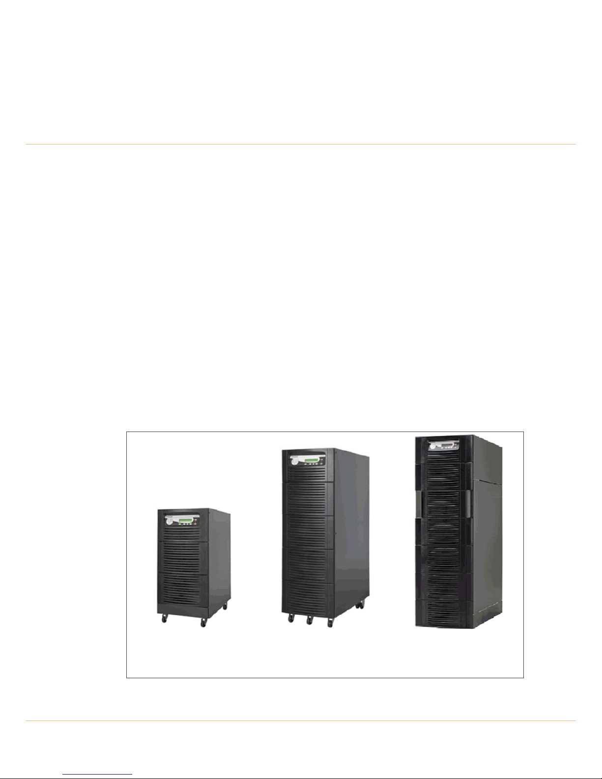
The Kohler PW 5000/TP UPS range covers 10, 15, 20, 25, 30, 40 and 50kVA models, in three different sized
cabinets, that can be employed in a Single or Multi-Module configuration.
Figure 2.1 Kohler PW 5000/TP Cabinet details
Cabinet A
10kVA, 15kVA, 20kVA
(WxHxD = 345x720x710)
Cabinet B
10kVA, 15kVA, 20kVA, 25kVA
(WxHxD = 345x1045x710)
Cabinet C
25kVA, 30kVA, 40kVA, 50kVA
(WxHxD = 440x1420x910)

2: Description
2-2 UPS412-01-01 Kohler PW 5000/TP User Manual Dated 17-11-11
2.2.1 Single/Multi-cabinet configurations
The Kohler PW 5000/TP UPS may be configured to operate as a single cabinet, or several (up to 20)
cabinets can be connected in parallel to operate as a multi-module UPS system. A multi-module
configuration is generally used either to increase the system’s total power capacity, or to provide module
redundancy. This manual describes the installation , configuration and ope ration of both single and multi module systems.
Note: Although the UPS single/multi configuration can be modified in the field it is generally specified on
ordering so that the module can be configured and fully tested in the fa ctory prior to despatch.
2.3 Advanced Design Features
2.3.1 Input booster technology
The UPS module’s inbuilt advanced booster technology results in a perfect sinusoidal in put power quality at
0.99 input power factor with a harmonic content of 3% THD(i). This leads to a more reliable total system
operation and savings in generator and transformer sizing, as losses in the windings are minimised. It also
means that traditional harmonic filters are no longer required.
The high power factor presented by the UPS on the incoming mains supply minimises cabling and fusing
costs due to the resulting lack of reactive power consumption. This, together with the accompanying low
harmonic currents, provide the following benefits:
• No additional losses in wires and cables.
• No extra heating of transformers and generators.
• No over sizing of generators.
• No false circuit breaker tripping and malfunction.
• No erratic operation of computers, telecommunication, monitors, electronic test equipment etc.
• No resonance with power factor correction capacitors.
2.3.2 Flexible battery management
This equipment employs a flexible battery management which avoids premature deterioration of battery life
by advanced management of battery charging and preventive failure diagnostics.
The major benefits are:
• AC-ripple free battery charging due to a dc-dc charger separated from the rectifier and inverter.
• Wide range of number of battery blocks (22-50 blocks of 12V; depending on autonomy times).
• UPS's wide input voltage operating window extends the battery life due to fewer discharge cycles.
• Battery discharge protection caused by load jumps.
• Proactive battery protection from false manipulations and inadequate charging voltages.
• Proactive battery failure detection thanks to Advanced Battery Diagnosis (ABD) - Algorithm.
• User selectable battery tests.
• Optional temperature compensated charging to enhance battery life.
2.3.3 Decentralized Parallel Architecture (DPA)
The Kohler PW 5000/TP system features DPA paralleling technology that provides n+x redundancy without
introducing a single-point-of-failure. The modules utilizing the DPA technology are completely autonomous
by means of individual power units, bypasses, CPUs, control panels and separate battery configuration.
2.4 Warranty
The Kohler PW 5000/TP UPS is supplied with a limited warranty that the UPS and its component parts are
free from defects in materials and workmanship for a period of one year from the date of original
commissioning or fifteen months from the date of original delivery, whichever is the sooner. Th is warranty is
the only warranty given and no other warranty, express or implied, is provided.
This warranty is invalidated if the UPS is put into use without having been commissioned by a fully trained
and authorised person. This warranty does not apply to any losses or damages caused b y misuse, abuse,

UPS412-01-01 Kohler PW 5000/TP User Manual Dated 17-11-11 2-3
2: Description
negligence, neglect, unauthorised repair or modification, incorrect installation, inappropriate environment,
accident, act of God or inappropriate application.
If the UPS fails to conform to the above within the warranty period then Kohler Uninterruptible Power. will, at
its sole option, repair or replace the UPS. All repaired or replaced parts will remain the property of Kohler
Uninterruptible Power.
As a general policy, Kohler Uninterruptible Power does not recommend the use of any of its products in life
support applications where failure or malfunction of the product can be reasonably expected to cause failure
of the life support device or to significantly affect it’s safety or effectiveness. Kohler Uninterruptible Power
does not recommend the use of any of its products in direct patient care. Kohler Uninterruptible Power will not
knowingly sell its products for use in such applications unless it receives in writing assurances satisfactory to
Kohler Uninterruptible Power that the risks of injury or damage have been minimized, the customer assumes
all such risks and the liability of Kohler Uninterruptible Power is adequately protected under the
circumstances
2.5 Extended Warranty
The Standard Warranty may be enhanced by protecting the UPS with an Extended Warranty Agreement
(maintenance contract).
An Extended Warranty Agreement enhances the standard warranty by providing the following:
• Regular preventative maintenance inspections.
• Guaranteed speed of response to operational problems.
• 24 hour telephone support.
• Fully comprehensive cover – excluding batteries and capacitors.
Contact the Service Support Hotline on +65 6302 0708 for further details.
2.6 Additional Service/Maintenance Support
In addition to providing support for the Ko hler PW 5000/TP UPS, Koh ler Uninterruptible Powe r are able to
provide maintenance and support on a wide range of different UPS products.
If you are interested in an extended warranty for your Kohler PW 5000/TP UPS, or any other UPS you may
have, please complete the enquiry form shown opposite and return or FAX to:
CAUTION: The UPS may contain batteries which must be re-charged for a minimum of 24
hours every six months to prevent deep-discharging. Batteries that have been, for whate ver
reason, deep-discharged are not covered by the warranty.
Regional Office (South East Asia)
Kohler Uninterruptible Power.
7 Jurong Pier
Singapore 619159
Tel: +65 6302 0708
Fax: +65 6302 0717
Email: serviceUPS.sg@kohler.com

2: Description
2-4 UPS412-01-01 Kohler PW 5000/TP User Manual Dated 17-11-11
Thank you for your enquiry, which will receive our prompt attention.
If you need to contact us immediately on +65 63020708,
or E-mail us on serviceUPS.sg@kohler.com
Regional Office (South East Asia)
Kohler Uninterruptible Power
7 Jurong Pier
Singapore 619159
Tel: +65 63020708
Name: ............................................................................................
Job Title: ................................. .. ..................................... ... .................
Company: ............................................................................................
Address: ............................................................................................
............................................................................................
............................................................................................
............................................................................................
Post Code .......................................................... ... ...............................
Tel. ............................................................................................
Fax. ............................................................................................
E-mail ............................................................................................
Please contact me to discuss:
Extended Warranty options for my Kohler PW 5000/TP UPS
Extended warranty options for my UPS System as below:
Manufacturer:...................................................................
Model Nº:..........................................................................
Rating kVA:.......................................................................
Replacement Batteries......................................................................
Other ................................... ...............................(please specify)
Fax to: +65 6302 0717
www.kohlerups.sg

UPS412-01-01 Kohler PW 5000/TP User Manual Dated 17-11-11 3-1
3
Installation
3.1 Introduction
This chapter contains all the information necessary for the correct unpacking, positioning, cabling a nd
installation of the Kohler PW 5000/TP UPS.
3.2 Receipt of the UPS
The UPS and accessories are delivered on a specifically designed pallet that is easy to move with a forklift or
a pallet jack.
The packing container protects the UPS from mechanical and environmental damage. This protection is
further increased by wrapping the Kohler PW 5000/TP UPS with a plastic sheet.
Upon receiving the UPS, carefully examine the packing container and the UPS for any sign of physical
damage. The outside 'Tip&Tel' (“FRAGILE” and “ARROW”) indicator should be intact if the equipment has
been transported in an upright position. In case of rupture (or if they are suspect) inform the carrier and
Kohler Uninterruptible Power immediately.
Ensure that the received UPS corresponds to the descripti o n i ndi ca te d in the delivery note.
3.2.1 Site transportation
If you transport the UPS equipment after it has been off-loaded (for example, for storage or moving to a
different installation location) please observe the following precautions.
WARNING: All the operations described in this section must be performed by authorised
electricians or suitably qualified personnel.
Kohler Uninterruptible Power will take no responsibility for any persona l or material damage
caused by incorrect cabling or operations, or activities which are not carried out in strict
accordance with the instructions contained in this manual.
CAUTION: When off loading the UPS always keep it in an upright position.
Do not drop the equipment.
Do not stack the pallets due to the high-energy batteries involved and the heavy weight.
CAUTION: Visible transport damages must be notified to the carrier immediately after receipt!
Other claims for shipping damage must also be filed immediately and the carrier must be
informed within 7 days of receipt of the equipment.
Packing materials should be stored for further investigation.
CAUTION: Potential dangers:
– Do not tilt the UPS or Battery Cabinet by more than 10° as it might damage the equipment.
If the equipment has been tilted do not connect it to the mains electricity supply.
– The weight of the UPS system could cause serious injuries to personnel or other equipment
in the surrounding area.
CAUTION: Storage:
– The UPS should be stored in the original packing and shipping carton.
– The recommended storing temperature for the UPS system and batteries is between +5 °C
and +40°C.
– The UPS system and the battery sets must be protected from humidity < 90% RH (noncondensing).
3: Installation
3-2 UPS412-01-01 Kohler PW 5000/TP User Manual Dated 17-11-11
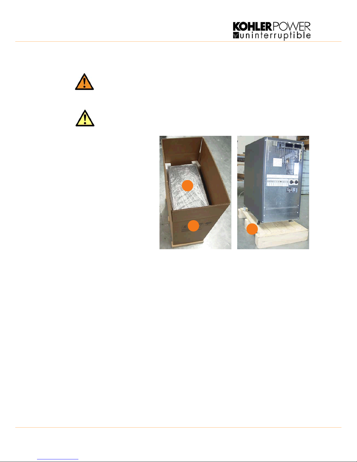
3.2.2 Unpacking the UPS
The smaller cabinets (cabinets A & B) are attached to the shipping pallet, wrapped in polythene and
protected by a sturdy cardboard covering. The larger cabinet (cabinet C) is shipped in a wooden case.
1. Ensure that the floor surface is
level and suitable for wheeling
and taking the heavy weight.
2. Remove cardboard packing
container by pulling it upwards.
The packaging will contain a
wooden ramp.
3. Remove the protective plastic
cover and any other packing
around the UPS.
4. Remove the fixings securing
the UPS to the pallet.
5. Position the enclosed ramp at
the rear side of the cabinet and
roll the UPS down the ramp.
6) Retain the packaging materials
for future shipment of the UPS.
7) Examine the UPS for any sign of
damage and notify your carrier or
supplier immediately if damage is
apparent.
Checking the nameplate
Before proceeding, check that the technical specifications on the nameplate, situated on the rear of the U PS
or behind the front internal door, correspond s to the purchased material mentioned in the goods delivery
note.
3.2.3 Batteries
The batteries connected to the UPS are usually of a sealed , maintenance-free design . The batteries can be
mounted either within the UPS, in an external battery cabinet, or on a bespoke battery rack, depending on the
required autonomy time and paralleling arrangement. For optimum reliability a separate battery string should
be connected to each individual UPS. The batteries are u sually shipped separately and fitted by a
manufacturer-approved engineer when the UPS is commissioned.
If the UPS is delivered without batteries, Kohler Uninterruptible Power is not responsible for any damage or
malfunctioning caused to the UPS by the incorrect supply, storage, installation or connection of batteries by
third parties.
WARNING: The UPS system, the battery cabinet (option) and the batteries are heavy and
may tip during transportation causing serious injury if the unpacking instructions are not
followed closely.
CAUTION: Before you finally unpack the equipment, remove any additional exte rnal shipping
packaging and visually check that the ‘Tip&Tel’ indicator (“FRAGILE” and “ARROW”) on the
packing container is intact.
Figure 3.1 Unpacking cabinets A & B
3
2
4

UPS412-01-01 Kohler PW 5000/TP User Manual Dated 17-11-11 3-3
3: Installation
3.3 Storage
3.3.1 UPS storage
If you plan to store the UPS prior to use, it should be kept in a clean, dry environment with an ambient
temperature between -25°C to +70°C and relative humidity of less than 90%.
If the UPS is removed from the packing container you must also ensure you protect it from dust.
3.3.2 Battery
The storage capability of the UPS batteries depends greatly on the ambient temperature. It is important not to
store the UPS batteries for longer than 6 months at 20°C, 3 months at 30°C or 2 months at 35°C storage
temperature without recharging the battery.
For longer term storage the battery must be fully recharged every 6 months @20°C.
3.4 Positioning
3.4.1 Planning the installation
A certain amount of pre-planning will help ensure smooth, trouble-free equipment installation. The following
guidelines should be taken into account when planning a suitable UPS location and environment.
1. The equipment must be installed and transported in a upright position.
2. The floor at the installed location and en-route from the off-loading point must be able to safely take the
weight of the UPS and battery equipment plus fork lift during transit. The floor material where the UPS is
to be located should be non-flammable.
3. The UPS cabinet requires space to bottom/front and back to enable cool ing airflow. Allow a minimum of
200mm clearance at the back of the cabinet. Suitable ventilation airflow (not exceeding +40°C) must be
provided (See Figure 3.2).
4. All parts of the UPS requiring access for maintenance, servicing and user operatio n are acce ssible fro m
the front and rear. Reserve a minimum of 900mm space at the front of the UPS cabinet.
5. An ambient temperature of 20°C is recommended to achieve a long battery life.
6. Avoid high ambient temperature, moisture and humidity.
In summary
The UPS should be located where:
a) Humidity (< 90% non-condensing) and temperature (+15°C / + 25°C) are within prescribed limits.
b) Fire protection standards are respected.
c) Cabling can be performed easily.
d) A minimum 900mm front accessibility is available for service or periodic maintenance.
e) Requested air cooling flow is available.
f) The air conditioning system can provide a sufficient amount of air cooling to keep the room at, or
below, the maximum desired temperature.
g) No dust or corrosive/explosive ga ses are present.
h) The location is vibration free.
i) If the UPS is to be installed in bayed enclosures, partition walls have to be installed.
CAUTION: Sealed batteries must never be stored in a discharged or partially discharged state.
Extreme temperature, under-charge, overcharge or over-discharge will destroy the batteries!
Key Point: Note the following:
• Charge the battery both before and after storing.
• Always store the batteries in a dry, clean, cool environment in their original packaging.
• If the packaging is removed protect the batteries from dust and humidity.
3: Installation
3-4 UPS412-01-01 Kohler PW 5000/TP User Manual Dated 17-11-11
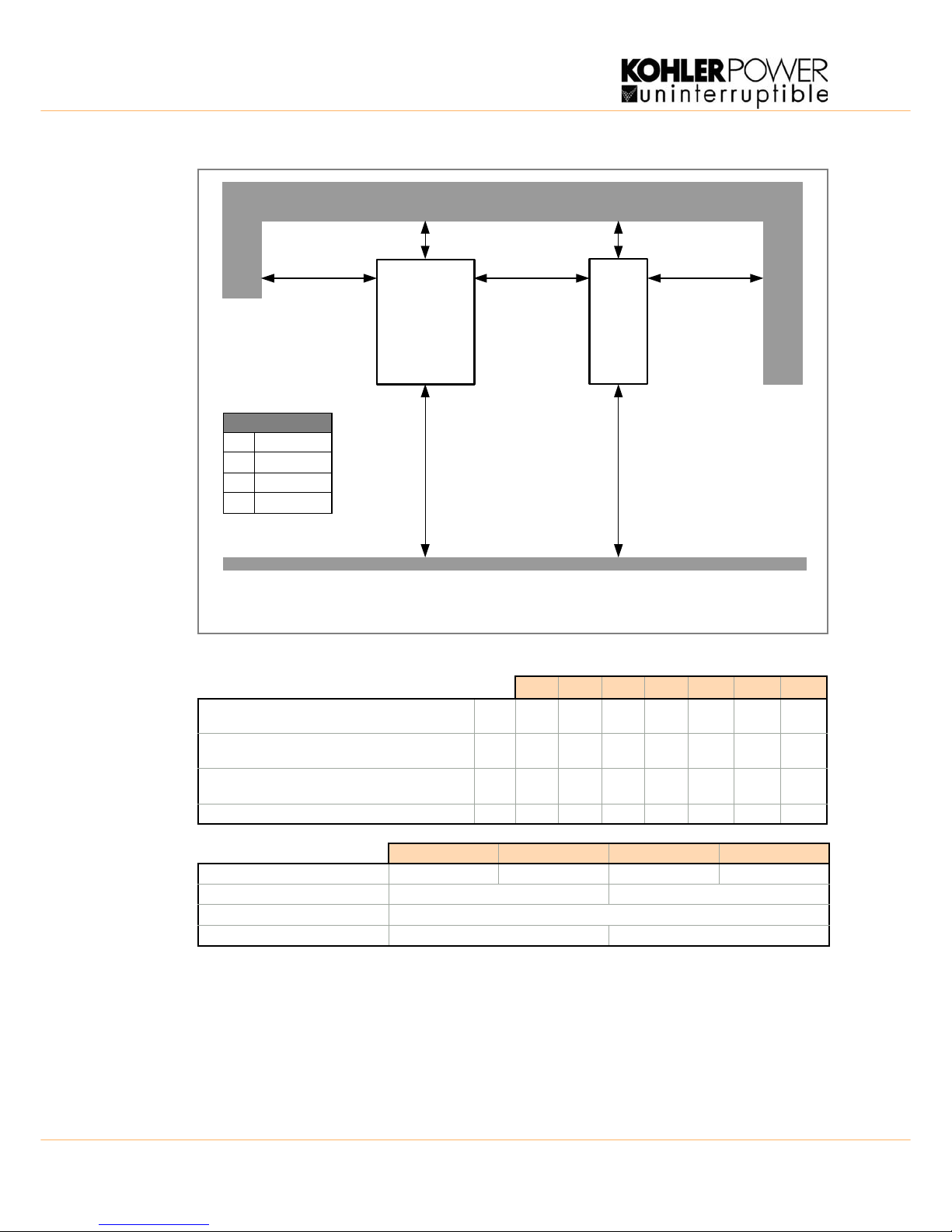
Figure 3.2 UPS Space Recommendations
10kVA 15kVA 20kVA 25kVA 30kVA 40kVA 50kVA
Heat Dissipation with 100% Non-linear Load per
range (EN 62040-3)
W 600 900 1100 1400 1700 2300 2900
Heat Dissipation with 100% Non-linear Load per
range (EN 62040-3)
BTU/h 2048 3072 3754 4778 5802 7850 9898
Airflow (25°C - 30°C) with 100% Non-linear Load per
range (EN 62040-3)
m³/h 150 150 150 150 570 570 570
Heat Dissipation without load W 120 150 150 170 250 300 350
Cabinet A Cabinet B Cabinet C Batt Cab C
Dimensions (WxHxD)mm 345x720x710 345x1045x710 440x1420x910 480x1420x940
Maintenance/Service Accessibility Top, rear, front, left and right side Top, front, left and right side
Positioning Min. 200mm rear space required for ventilation
Input and Output Power Cabling From the bottom at the rear. From the bottom at the front
UPS
Z
Front
VX600 mm
600 mm
Access Space
BATTERY
CABINET
(option)
Front
Y*
VXX
Y*Z200 mm
900 mm
Z
Y*
*Although the diagram shows 200mm is required at the rear of the cabinet, ‘A’ and ‘B’ cabinets should be
cabled such that the cabinet can be pulled forward to give access to the rear connections.

UPS412-01-01 Kohler PW 5000/TP User Manual Dated 17-11-11 3-5
3: Installation
3.5 UPS Power Cabling
3.5.1 General requirements (preparation and planning)
It is the customer’s responsibility to provide all external fuses, isolators and cables used to connect the UPS
input and output power supplies. The information in thi s section should help i n the planning and prep aration
of the UPS power cabling.
The UPS input supply and bypass supply should be connected to the utility mains through a LV-Distribution
board and protected by a circuit breaker or fuse. This provides overload protection and also a means of
isolating the UPS from the mains supply when required. Similarly, the UPS output supply should be
connected to the load equipment via a suitably fused output distribution panel.
The UPS can be wired with a ‘single feed’ input (standard), whereby the UPS input supply is internally
connected to the UPS bypass circuit, or it can be wired with a ‘dual feed’ input – where the UPS bypass
circuit is connected to a dedicated ‘bypass’ supply (See Figure 3.4).
Figure 3.4 identifies the UPS input/output cabling requirements and provides information regarding the
necessary fuse and cable ratings, and cable sizing.
Figures 3.6/ 3.7 show details of the power terminal connections with in the UPS including connectio n sizes
and recommended tightening torque. This illustration shows that the UPS unit requires the following power
cables:
Rectifier (In):
• three-phase (1L1, 1L2, 1L3)
• neutral (1N)
• protective earth (PE) connection for the rectifier input
Bypass (In) (Dual feed system only):
• three-phase (2L1, 2L2, 2L3)
• neutral (2N)
• protective earth (PE) connection for the bypass if used as ‘Dual Feed’ input
Load (Out):
• three-phase (3L1, 3L2, 3L3)
• neutral (3N)
• protective earth (PE) connection for the load output
External Battery:
• Plus (+)
• Common (N)
• Minus (-)
• protective earth (PE) connection for the external batteries
• the UPS internal batteries must be disconnected if external batteries are used. Under no
circumstances should external and internal batteries be connected together in parallel.
Key Point: This information is given for guidance only. All fuses, isolators and power cables must
be rated and installed in accordance with the prescribed IEC standards or local regulation.
3: Installation
3-6 UPS412-01-01 Kohler PW 5000/TP User Manual Dated 17-11-11
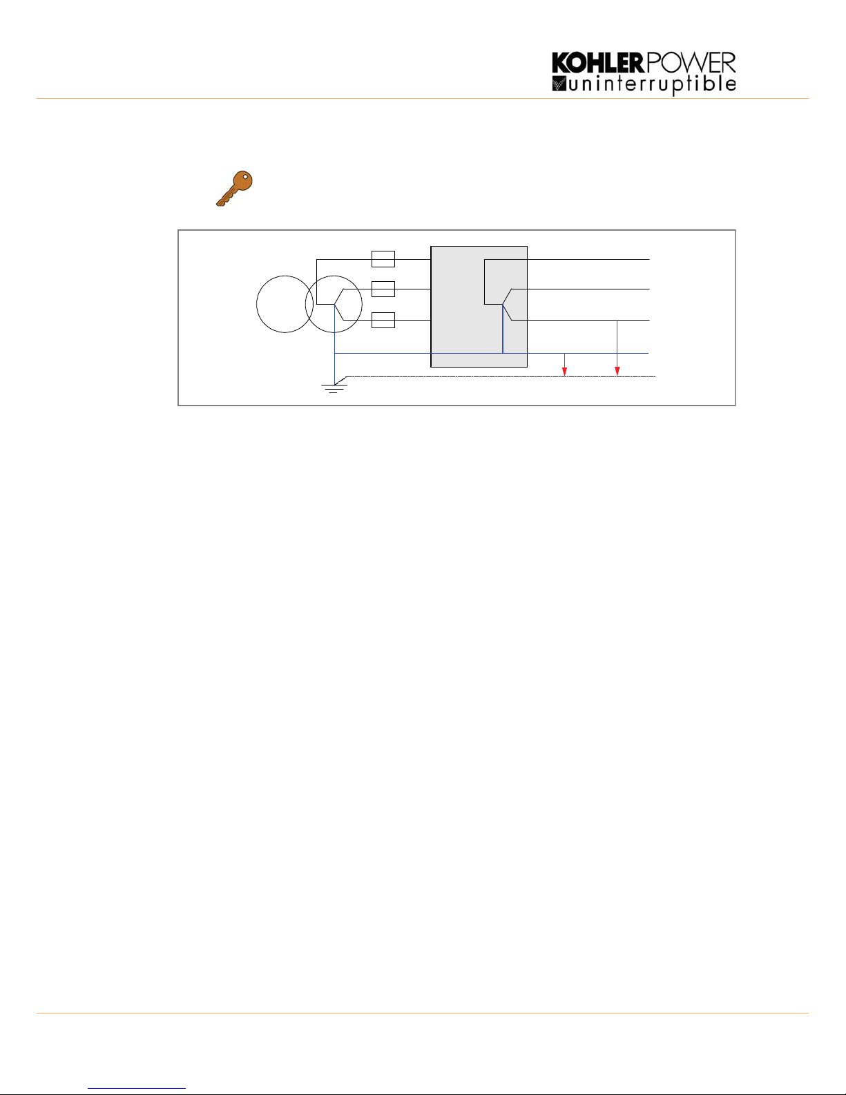
Input neutral grounding
Figure 3.3 Input neutral grounding
Key Point: Input neutral is required to operate the rectifier.
In TN-S systems, no 4-pole input switches or circuit breakers should be used.
During battery operation the neutral must always be grounded.
0V
230V
UPS
UPS412-01-01 Kohler PW 5000/TP User Manual Dated 17-11-11 3-7
3: Installation
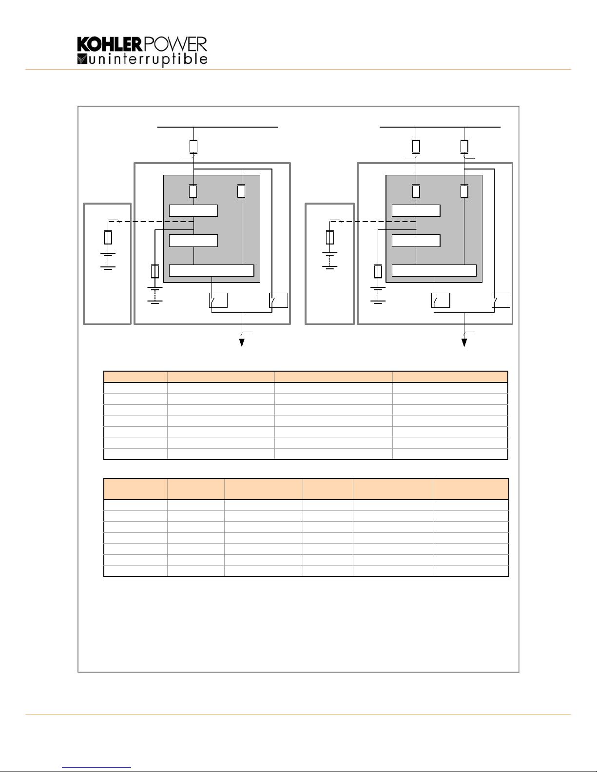
Figure 3.4 Kohler PW 5000/TP fuse & cable rating
Rectifier
Inverter
Static Switch
FA1
Fuse B
Load
DUAL INPUT FEED
Cable D
Cable B
Fuse C
Cable C
Rectifier
Inverter
Static Switch
Fuse A
Load
SINGLE INPUT FEED (standard)
Mains (3x380/220V,
3x400/230V,
3x415/240V)
Cable D
Cable A
EXTERNAL
BATTERY
CABINET
(option)
FA2FA1 FA2
EXTERNAL
BATTERY
CABINET
(option)
FA3
(F1)
FA3
(F1)
Int. Batts. Int. Batts.
FA4 FA4
Output
Switch
Maint.
Bypass
IA2 IA 1
Maint.
Bypass
IA2 IA1
Output
Switch
SINGLE INPUT FEED
DUAL INPUT FEED
Notes:
1. Fuse and Cable recommendations to IEC 60950-1:2001
2. The fuse and cable rating details in the above tables are a recommendation only.
3. The UPS must be installed to prescribed IEC or local regulations.
4. External DC Cables and Battery fuses are bespoke to the installation.
Power (kVA) Fuse A (Agl/CB) (A) Cable A (mm²) Cable D (mm²)
10 3 x 20 5 x 2.5 5 x 2.5
15 3 x 32 5 x 4.0 5 x 4.0
20 3 x 40 5 x 6.0 5 x 6.0
25 3 x 40 5 x 6.0 5 x 6.0
30 3 x 63 5 x 10 5 x 10
40 3 x 80 5 x 25 5 x 25
50 3 x 80 5 x 25 5 x 25
Power (kVA) Fuse B
(Agl/CB) (A)
Cable B (mm²) Fuse C
(Agl/CB) (A)
Cable C (mm²) Cable D (mm²)
10 3 x 20 5 x 2.5 3 x 20 5 x 2.5 5 x 2.5
15 3 x 32 5 x 4.0 3 x 32 5 x 4.0 5 x 4.0
20 3 x 40 5 x 6.0 3 x 40 5 x 6.0 5 x 6.0
25 3 x 40 5 x 6.0 3 x 40 5 x 6.0 5 x 6.0
30 3 x 63 5 x 10 3 x 63 5 x 10 5 x 10
40 3 x 80 5 x 25 3 x 80 5 x 25 5 x 25
50 3 x 80 5 x 25 3 x 80 5 x 25 5 x 25
3: Installation
3-8 UPS412-01-01 Kohler PW 5000/TP User Manual Dated 17-11-11
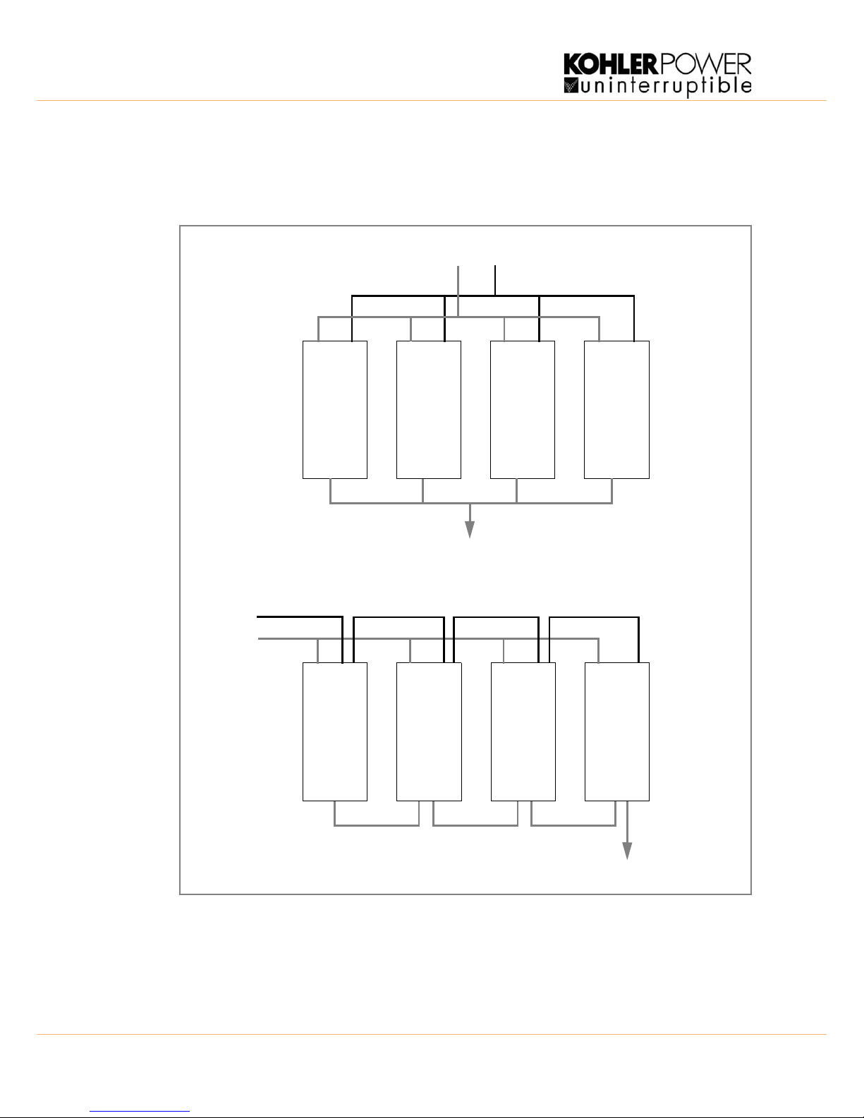
Cabling a parallel system
In order to achieve equal load sharing between the UPS-cabinets in a multi-cab inet installation, the input
cables from the input distribution board to each UPS cabinet should be of equal length. Similarly the UPS
output cables to the output distribution board should be of equal length (See Figure 3.5).
Figure 3.5 Cable lengths for multi cabinet configuration s (as s umi ng a dual input supply)
UPS 1 UPS 2 UPS 3 UPS 4
UPS 1 UPS 2 UPS 3 UPS 4
Recommended cable configurations
The cable configuration below is not recommended
Bypass Feed
Rectifier Feed
To Load
To Load
Bypass Feed
Rectifier Feed
 Loading...