

Page 1
34 590 01 Rev. A
KohlerPower.com
EN
PRO 12.3 EFI
Generator Owner's Manual
IMPORTANT: Read all safety precautions and instructions carefully before
operating equipment.
Ensure generator is stopped and level before performing any
maintenance or service.
Record product information to reference when ordering parts or obtaining warranty coverage.
Specication
Serial Number
Purchase Date
ESS
FRC
Page 2
2 34 590 01 Rev. AKohlerPower.com
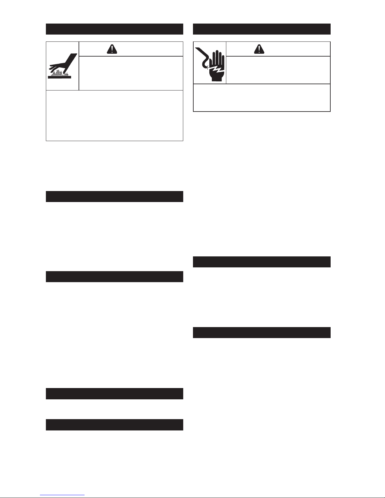
CAUTION
Electrical Shock
can cause injury.
Do not touch
wires while
generator is
running.
Never operate generator in
rain or snow.
Never touch generator
with wet hands or electrical
shock may occur.
WARNING
Rotating Parts
can cause
severe injury.
Stay away while
generator is in
operation.
Keep hands, feet, hair,
and clothing away from all
moving parts to prevent
injury. Never operate
generator with covers,
shrouds, or guards
removed.
WARNING
Accidental
Starts can cause
severe injury or
death.
Disconnect and
ground spark
plug lead(s)
before servicing.
Before working on
generator or equipment,
disable engine as follows:
1) Disconnect spark plug
lead(s). 2) Disconnect
negative (–) battery cable
from battery.
Do not allow children to
operate generator.
WARNING
High Pressure
Fluids can
puncture skin
and cause
severe injury or
death.
Do not work
on fuel system
without proper
training or safety
equipment.
Fluid puncture injuries are
highly toxic and hazardous.
If an injury occurs, seek
immediate medical
attention.
WARNING
Hazardous
Voltage.
Backfeed to
utility system
can cause
property
damage, severe
injury, or death.
Never plug a portable
generator directly into a
building outlet.
If generator is used for
standby power, have a
certied, licensed electrician
install an automatic
transfer switch to prevent
inadvertent interconnection
of standby and normal
sources of supply.
WARNING
Explosive Fuel
can cause res
and severe
burns.
Do not ll fuel
tank while
generator is hot
or running.
Gasoline is extremely
ammable and its vapors
can explode if ignited.
Never refuel while smoking
or in vicinity of an open
ame. Store gasoline only
in approved containers, in
well ventilated, unoccupied
buildings, away from sparks
or ames. Spilled fuel
could ignite if it comes in
contact with hot parts or
sparks from ignition. Never
use gasoline as a cleaning
agent.
WARNING
Hot Parts can
cause severe
burns.
Do not touch
generator while
operating or just
after stopping.
Never operate generator
with heat shields or guards
removed. Do not modify
generator.
Place generator in a place
where pedestrians or
children are not likely to
touch generator.
Be sure to carry generator
only by its carrying handles.
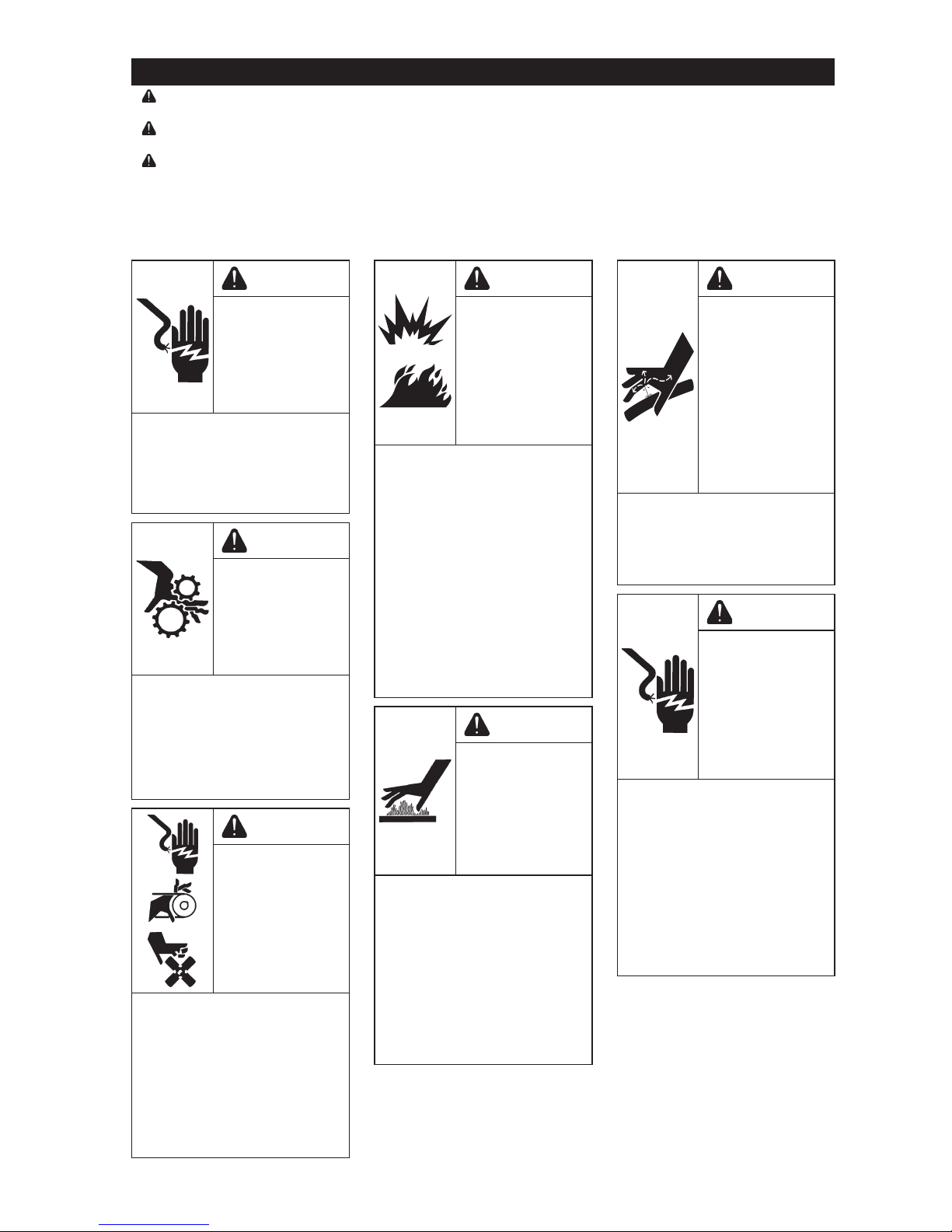
Safety Precautions
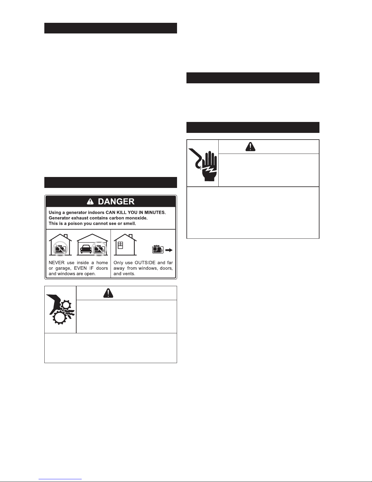
DANGER: A hazard that will result in death, serious injury, or substantial property damage.
WARNING: A hazard that could result in death, serious injury, or substantial property damage.
CAUTION: A hazard that could result in minor personal injury or property damage.
NOTE: is used to notify people of important installation, operation, or maintenance information.
Read this manual carefully before operating this machine. This manual should stay with this
machine if it is sold.
Page 3
3
34 590 01 Rev. A
KohlerPower.com
EN
California Proposition 65 Warning
Engine exhaust from this product contains chemicals known
to State of California to cause cancer, birth defects, or other
reproductive harm.
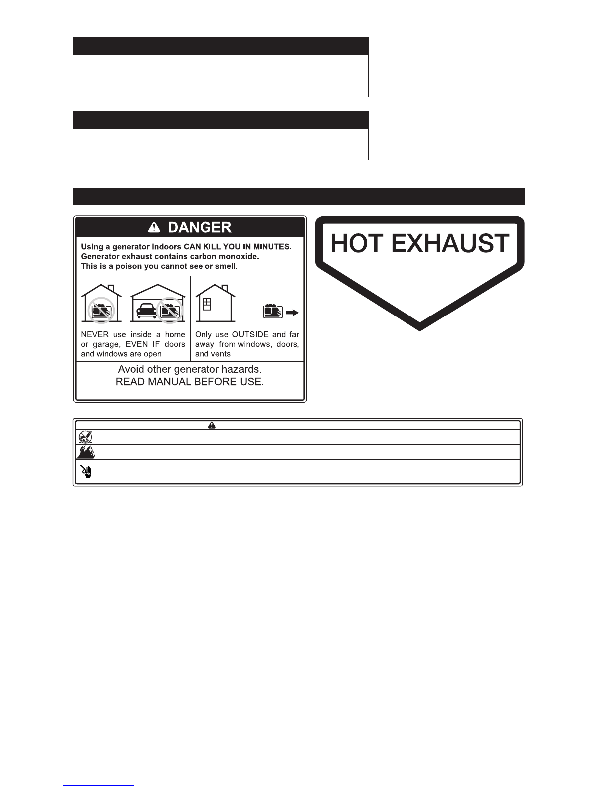
Important Labels on Generator
WARNING / ADVERTENCIA / AVERTISSEMENT
● Hot parts can cause severe burns. / Las piezas calientes pueden causar quemaduras graves. / Les pièces chaudes peuvent causer de graves brûlures.
● Do not touch generator while operating or just after stopping. / No toque el generador durante el funcionamiento o inmediatamente después de pararse. / Ne touchez pas le générateur pendant qu'il tourne ou si
vous venez tout juste de l'arrêter.
● Explosive Fuel can cause fires and severe burns. / La explosión del carburante puede provocar incendios y quemaduras graves. / Carburant explosif pouvant causer des incendies et des brûlures graves.
● Do not fill fuel tank while generator is hot or running. / No llene el tanque de combustible mientras el generador esté caliente o funcionando. / N'ajoutez pas de carburant si le moteur est chaud ou s'il tourne.
● Electrical shock can cause injury. / Las descargas eléctricas pueden provocar lesiones. / Les chocs électriques peuvent causer des blessures.
● Do not touch wires while generator is running. / No toque los cables con el generador en funcionamient. / Ne touchez pas aux le générateur pendant que le moteur tourne.
● Do not connect generator to a building's electrical system unless using an isolation (transfer) switch installed by a certified, licensed electrician. / No conecte el generador al sistema eléctrico de un edificio a menos
que use un aislamiento (transferencia) interruptor instalado por un electricista certificado y certificado. / Ne branchez pas le générateur dans le système électrique d’un bâtiment sauf si un commutateur-converteur
a été installé par un électricien agréé et compétent.
California Proposition 65 Warning
This product contains chemicals known to State of California
to cause cancer, birth defects, or other reproductive harm.
Page 4
4 34 590 01 Rev. AKohlerPower.com
W
Z
AG
AF
AE
AD
AB
AC
AA
V
U
C
B
F
T
Y
S
L
M N
R
Q
P
AH
AH
X
A
K
D
H
I
F
O
J
E
G
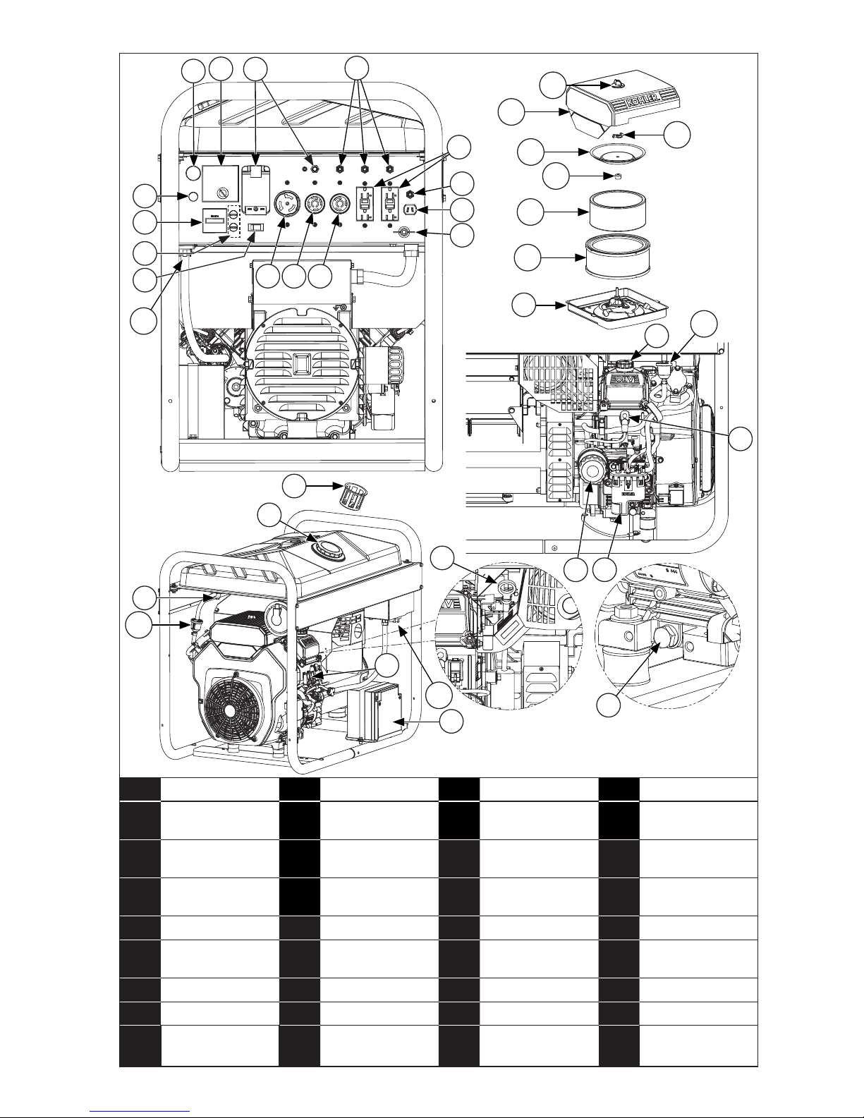
A Hour Meter B MODYS C Pilot Light D MIL Light
E Circuit Breaker F Circuit Protector G
GFCI
Receptacle
H
12V DC
Receptacle
I Ground Terminal J Fuse K Auto Idle L
240/120V/50A
Electrical Socket
M
240/120V/30A
Electrical Socket
N
120V/30A
Electrical Socket
O Fuel Tank Cap P Fuel Valve
Q Fuel Filter R Engine Fuses S Starter Battery T Dipstick
U Oil Drain Plug V Oil Filter W
Fuel Pump
Module
X Spark Plug
Y Oil Fill Cap Z Air Cleaner Base AA Paper Element AB Precleaner
AC Rubber Seal AD Element Cover AE Wing Nut AF Air Cleaner Knob
AG
Air Cleaner
Cover
AH
Unique EFI
Fuel Filter
AI
Wireless
Connect
AJ
Diagnostic
Button
AJ
AI
Page 5
5
34 590 01 Rev. A
KohlerPower.com
EN
Pre-Start Checklist
1. Ensure generator is at least 3.3 ft. (1 m) from
building or other equipment and not covered
with any material.
2. Refer to all warning labels prior to starting.
3. Check oil level. Add oil if low. Do not overll.
4. Check fuel level. Add fuel if low. Stop
refueling when indicator reaches F (full)
level. Check fuel system components and
lines for leaks. Never refuel while unit is
running.
5. Check starter battery (S).
6. Ground generator.
7. Check that air cleaner components and all air
inlets are unobstructed, equipment covers,
and guards are in place and securely
fastened.
8. Ensure electrical devices (load) are not
connected to generator.
Starting
WARNING
Rotating Parts can cause severe
injury.
Stay away while generator is in
operation.
Keep hands, feet, hair, and clothing away
from all moving parts to prevent injury. Never
operate generator with covers, shrouds, or
guards removed.
NOTE: Auto Idle (K) switch must be in OFF
position when using electric devices
that require a large starting current,
such as a compressor or a submersible
pump. Auto Idle (K) controls engine
speed according to connected load.
Results are better fuel consumption
and less noise.
NOTE: MODYS (B) automatically performs 5
start-up attempts.
1. Turn main AC circuit breaker (E) OFF.
2. Turn fuel valve (P) ON.
3. Turn MODYS (B) key to ON position.
4. Press START button on MODYS (B).
5. Test GFCI receptacles (G).
Cold Weather Starting
1. Use proper oil for temperature expected.
2. Disengage all possible external loads.
3. Use fresh winter grade fuel. Winter grade
fuel has higher volatility to improve starting.
Operation
WARNING
Hazardous Voltage.
Backfeed to utility system can
cause property damage, severe
injury, or death.
Never plug a portable generator directly into
a building outlet.
If generator is used for standby power,
have a certied, licensed electrician install
an automatic transfer switch to prevent
inadvertent interconnection of standby and
normal sources of supply.
When running speed of generator has
stabilized (approximately 3 minutes):
1. Check that circuit breakers (E) are pushed in.
Press if necessary.
2. Connect appliances to be used to electrical
sockets (G, L, M and N) of generator.
3. Hour meter (A) shows number of hours that
generator has worked.
Angle of Operation
Do not operate this engine exceeding maximum
angle of operation; see specication table.
Engine damage could result from insufcient
lubrication.
Page 6
6 34 590 01 Rev. AKohlerPower.com
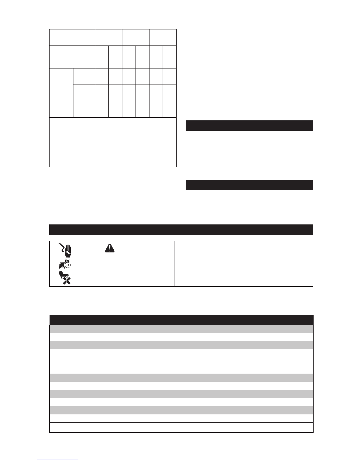
Cable Selection
Generator
Socket Type
10 A 16 A 32 A
Recommended
Cable Cross
Section
mm
2
AWG
mm
2
AWG
mm
2
AWG
Length
of
Cable
Used
0 to
50 m
4 10 6 9 10 7
51 to
100 m
10 7 10 7 25 3
101 to
150 m
1
10 7 16 5 35 2
1
This cable length is maximum permitted
length, and must not be exceeded.
Installation method=cables on raceway
or non-drilled tablet/Permitted drop in
voltage=5%/Multi-core conductors/Cable
type PVC 70°C (e.g. H07RNF)/Ambient
temperature=86° F (30° C).
Maintenance Instructions
WARNING
Before working on generator or equipment,
disable engine as follows: 1) Disconnect spark
plug lead(s). 2) Disconnect negative (–) battery
cable from battery.
Do not allow children to operate generator.
Accidental Starts can cause
severe injury or death.
Disconnect and ground spark
plug lead(s) before servicing.
Safety is an obligation of owner. Periodic inspection, adjustment and lubrication will keep your
generator in safest and most efcient condition possible. Most important points of generator
inspection, adjustment, and lubrication are explained on following pages.
Maintenance Schedule
First 25 Hours or Annually
1
● Service/replace precleaner (if equipped).
Every 100 Hours or Annually
1
● Change oil.
● Replace air cleaner element (AA).
● Remove and clean shrouds and cooling areas.
Every 200 Hours
1
● Replace unique Electronic Fuel Injection (EFI) fuel lter.
Every 200 Hours or Annually
1
● Change oil and lter (V).
Every 500 Hours or Annually
1
● Replace spark plugs (X) and set gap.
1
Perform these procedures more frequently under severe, dusty, dirty conditions.
Auto Idle
NOTE: Auto Idle will only function when unit is
on 120V function.
ON Position. When Auto Idle (K) switch is
in ON position, Auto Idle (K) controls engine
speed according to connected load. Results are
better fuel consumption and less noise.
OFF Position. When Auto Idle (K) switch is in
OFF position, engine runs at rated rpm (3,600
rpm) regardless of whether there is a load
connected or not.
NOTE: Turn Auto Idle to OFF when unit is using
240V conguration.
Stopping
1. Disconnect electrical devices and allow
engine to run without any load for 1-2
minutes.
2. Turn MODYS (B) key to OFF position
(generator stops).
3. Close fuel valve (P).
Engine Speed
NOTE: Do not tamper with governor setting to
increase maximum engine speed.
Overspeed is hazardous and will void
warranty.
Page 7
7
34 590 01 Rev. A
KohlerPower.com
EN
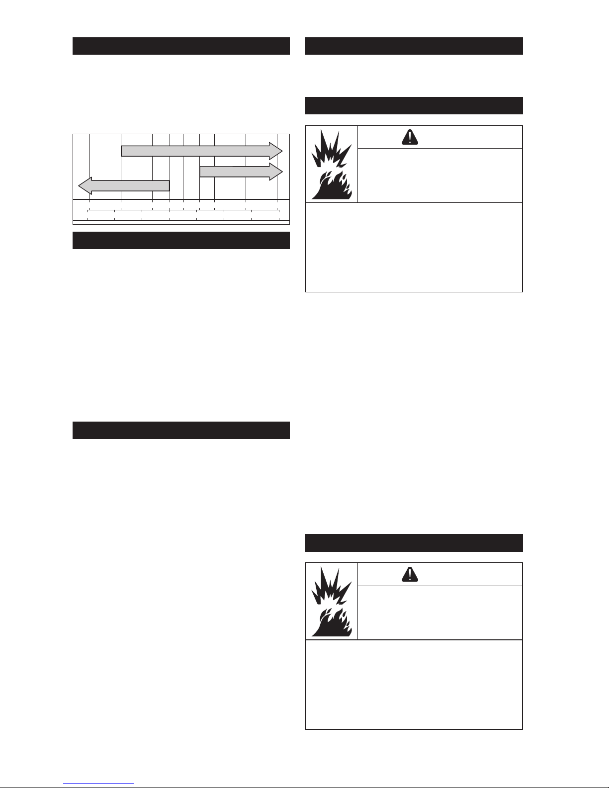
Oil Recommendations
We recommend use of Kohler oils for best
performance. Other high-quality detergent
oils (including synthetic) of API (American
Petroleum Institute) service class SJ or higher
are acceptable. Select viscosity based on air
temperature at time of operation as shown in
table below.
°F -20 020324060
50 80 100
°C -30 -20 -10 0 10 20 30 40
5W-30
10W-30
SAE 30
Check Oil Level
NOTE: To prevent extensive engine wear or
damage, never run engine with oil level
below or above operating range
indicator on dipstick (T).
Ensure engine is cool. Clean dipstick area of
any debris.
1. Remove dipstick (T); wipe oil off. Reinsert
dipstick (T) into tube; press completely down.
2. Remove dipstick (T); check oil level. Level
should be at top of indicator on dipstick (T).
3. If oil is low on indicator, add oil up to top of
indicator mark.
4. Reinstall and secure dipstick (T).
Change Oil and Filter
Change oil while engine is warm.
1. Clean area around dipstick (T) and oil drain
plug (U). Remove oil drain plug (U) and
dipstick (T). Allow oil to drain completely.
2. Clean area around oil lter (V). Place a
container under lter to catch any oil and
remove lter. Wipe off mounting surface.
Reinstall oil drain plug (U). Torque to 10 ft. lb.
(13.6 N·m).
3. Place new lter in shallow pan with open end
up. Fill with new oil until oil reaches bottom of
threads. Allow 2 minutes for oil to be
absorbed by lter material.
4. Apply a thin lm of clean oil to rubber gasket
on new lter.
5. Refer to instructions on oil lter (V) for proper
installation.
6. Fill crankcase with new oil. Level should be
at top of indicator on dipstick (T).
7. Reinstall dipstick (T) and tighten securely.
8. Start engine; check for oil leaks. Stop engine;
correct leaks. Recheck oil level.
9. Dispose of used oil and lter in accordance
with local ordinances.
Oil Sentry™ (if equipped)
This switch is designed to prevent engine
from starting in a low oil or no oil condition. Oil
Sentry™ will shut down a running engine.
Fuel Recommendations
WARNING
Explosive Fuel can cause res
and severe burns.
Do not ll fuel tank while
generator is hot or running.
Gasoline is extremely ammable and
its vapors can explode if ignited. Store
gasoline only in approved containers, in
well ventilated, unoccupied buildings, away
from sparks or ames. Spilled fuel could
ignite if it comes in contact with hot parts or
sparks from ignition. Never use gasoline as a
cleaning agent.
NOTE: E15, E20 and E85 are NOT approved
and should NOT be used; effects of
old, stale or contaminated fuel are not
warrantable.
Fuel must meet these requirements:
● Clean, fresh, unleaded gasoline.
● Octane rating of 87(R+M)/2 or higher.
● Research Octane Number (RON) 90 octane
minimum.
● Gasoline up to 10% ethyl alcohol, 90%
unleaded is acceptable.
● Methyl Tertiary Butyl Ether (MTBE) and
unleaded gasoline blend (max 15% MTBE by
volume) are approved.
● Do not add oil to gasoline.
● Do not overll fuel tank.
● Do not use gasoline older than 30 days.
Check Fuel Level
WARNING
Explosive Fuel can cause res
and severe burns.
Do not ll fuel tank while
generator is hot or running.
Gasoline is extremely ammable and
its vapors can explode if ignited. Store
gasoline only in approved containers, in
well ventilated, unoccupied buildings, away
from sparks or ames. Spilled fuel could
ignite if it comes in contact with hot parts or
sparks from ignition. Never use gasoline as a
cleaning agent.
Page 8
8 34 590 01 Rev. AKohlerPower.com
Engine Fuse Replacement
This engine has three (3) blade type automotive
fuses (R). Replacement fuses (R) must have
same rating as blown fuse. Use fuse chart
below to determine correct fuse (R).
Wire Color Fuse Rating
2 Solid Red Wires 10-amp Fuse
1 Red Wire with Black Stripe
1 Red Wire with White Stripe
10-amp Fuse
2 Purple Wires 30-amp Fuse
Air Cleaner
NOTE: Operating engine with loose or
damaged air cleaner components
could cause premature wear and
failure. Replace all bent or damaged
components.
NOTE: Paper element (AA) cannot be blown
out with compressed air.
Loosen knob (AF) and remove air cleaner cover
(AG).
Precleaner (AB):
1. Remove precleaner (AB) from paper element
(AA).
2. Replace or wash precleaner (AB) in warm
water with detergent. Rinse and allow to air
dry.
3. Saturate precleaner (AB) with new engine oil;
squeeze out excess oil.
4. Reinstall precleaner (AB) over paper element
(AA).
Paper Element (AA):
1. Clean area around element (AA). Remove
wing nut (AE), element cover (AD), and
paper element (AA) with precleaner (AB).
2. Separate precleaner (AB) from element (AA);
service precleaner (AB) and replace paper
element (AA).
3. Check condition of rubber seal (AC) and
replace if necessary.
4. Install new paper element (AA) on base (Z);
install precleaner (AB) over paper element
(AA); reinstall element cover (AD) and
secure with wing nut (AE).
Reinstall air cleaner cover (AG) and secure with
knob (AF).
Breather Tube
Ensure both ends of breather tube are properly
connected.
Visually check level of fuel. If necessary, ll up.
1. Unscrew fuel tank cap (O).
2. Fill fuel tank using a funnel, taking care not to
spill any fuel. Do not overll tank (there
should not be any fuel in ller neck).
3. Screw fuel tank cap (O) back on.
Fuel Filter
1. Open fuel tank cap (O).
2. Remove fuel lter (Q) from tank neck.
3. Clean fuel lter (Q) with a non-ammable
solvent or solvent with a high ash point. Dry
it fully. Replace as necessary.
4. Reinstall fuel lter (Q).
5. Reinstall fuel tank cap (O).
Electronic Fuel Injection (EFI) System
EFI is an electronically-controlled fuel
management system which is monitored by an
Electronic Control Unit (ECU). A Malfunction
Indicator Light (MIL) will illuminate if problems
or faults are detected. Servicing by a Kohler
portable dealer is necessary.
Fuel Line
High pressure fuel line meeting SAE R9
standard must be installed on Kohler Co.
engines equipped with an EFI system.
Fuel System Components
High pressure components inside fuel pump
module (W) are not serviceable. Engines are
equipped with a special EFI fuel lter (AH). See
Maintenance Schedule.`
Spark Plugs
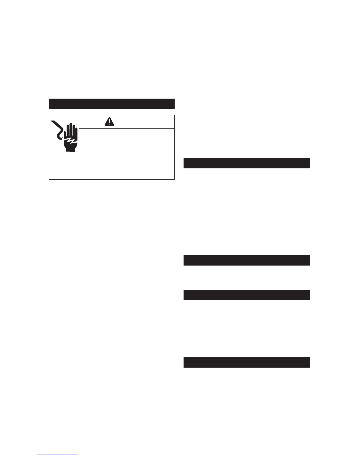
CAUTION
Electrical Shock can cause injury.
Do not touch wires while
generator is running.
Never operate generator in rain or snow.
Never touch generator with wet hands or
electrical shock may occur.
Clean out spark plug recess. Remove plug and
replace.
1. Check gap using wire feeler gauge. Adjust
gap, see specication table for adjustment.
2. Install plug into cylinder head.
3. Torque spark plug (X) to 20 ft. lb. (27 N·m).
Page 9
9
34 590 01 Rev. A
KohlerPower.com
EN
Air Cooling
WARNING
Hot Parts can cause severe
burns.
Do not touch generator while
operating or just after stopping.
Never operate generator with heat shields or
guards removed. Do not modify generator.
Place generator in a place where pedestrians
or children are not likely to touch generator.
Be sure to carry generator only by its
carrying handles.
Proper cooling is essential. To prevent over
heating, ensure air cooling inlet and outlet
areas are clean and unobstructed. Avoid
spraying water at wiring harness or any
electrical components. Refer to Maintenance
Schedule.
Ground Terminal
Ground terminal (I) connects earth line for
prevention of electric shock. When electric
device is grounded, be sure to ground
generator also.
Connect generator to ground: Attach a 6 AWG
(10 mm2) copper wire to generator’s ground
connection and to a galvanized steel grounding
rod (not provided) driven 3.3 ft. (1 m) into
ground.
Connecting Alternating Current (AC)
NOTE: Ensure all electric devices including
lines and plug connection are in good
condition before connection to
generator.
NOTE: Ensure total load is within generator
rated output.
NOTE: Ensure receptacle load current is within
receptacle rated current.
1. Start engine.
2. Ensure AC pilot light (C) is on.
3. Plug into AC receptacle (G, L, M or N).
4. Turn on any electric devices.
AC Rated Power
AC rated power is maximum amount of power
generator can support.
AC Maximum Power
AC maximum power is additional power
generator momentarily produces to aid in
starting of electrical devices requiring power
above generator's rated power requirements.
GFCI Receptacle
CAUTION
Electrical Shock can cause injury.
Do not touch wires while
generator is running.
Never operate generator in rain or snow.
Never touch generator with wet hands or
electrical shock may occur.
To reduce chance of electrical shock:
1. Do not attempt to operate equipment if
ground fault circuit interrupter (GFCI) RESET
button pops out repeatedly during use.
2. Remember that only receptacles labeled
GFCI have ground fault circuit interrupter
protection.
Ground Fault Circuit Interrupter (GFCI) stops
power to protected receptacles (G) if a ground
fault (electrical leak) is detected. If RESET
button pops out, equipment plugged into
receptacle (G) may be faulty. If this happens,
check equipment carefully. If equipment
appears to be in good condition, press RESET
button rmly until a click is heard. This will
restore power. If RESET button pops out again,
unplug equipment immediately. Contact a
Kohler portable dealer before attempting to use
it again.
GFCI Receptacle Test
1. Start generator.
2. Press TEST button, if functioning properly
RESET button should pop out, stopping
power to outlet.
3. If GFCI operation is correct, push RESET
button in. If GFCI operates incorrectly,
contact a Kohler portable dealer.
Overload (Capacity of Generator)
Never exceed rated load of generator (in Amps
and/or Watts) when it is running continuously.
See specications table for rated outputs.
Before connecting and operating generator,
calculate electrical power required by electric
appliances (in Watts). This electrical power
rating is usually found on manufacturer's
plate on bulbs, electrical appliances, motors,
etc. Sum total of power required by these
appliances should not exceed nominal power
rating of generator.
Circuit protectors (F) and circuit breaker (E)
will stop power to protected receptacles (G, H,
L, M or N) when an overload of a connected
electrical device is detected or AC output
voltage rises to protect generator and any
connected electric devices.
Page 10
10 34 590 01 Rev. AKohlerPower.com
When overload occurs and power generation
stops, proceed as follows:
1. Turn off any connected electric devices and
stop generator.
2. Reduce total wattage of connected electric
devices within application range.
3. Check for blockages in cooling air inlet and
outlet areas and around control unit. If any
blockages are found, remove them.
4. After checking, restart generator.
Battery Charging Using DC Receptacle
CAUTION
Electrical Shock can cause injury.
Do not touch wires while
generator is running.
Never operate generator in rain or snow.
Never touch generator with wet hands or
electrical shock may occur.
NOTE: This section refers to charging 12V
batteries in other equipment like motor
vehicles or off-road vehicles. No
jump-starting is possible.
NOTE: Follow safety procedures when
handling batteries to avoid damage to
electrical components and battery
explosions. Refer to battery
manufacturers safety data sheet on
safety risks of working with batteries.
Refer to battery manufacturer's
instruction on battery charging/
maintaining procedures.
NOTE: Generator DC rated voltage is 12V DC
circuit protector (F) will turn off
automatically if current above rated
ows during battery charging. Start
generator rst, then connect generator
to battery for charging. Before starting
to charge battery, ensure DC circuit
protector (F) is in RESET position. If
DC circuit protector (F) turns off again,
stop charging battery immediately and
contact a Kohler portable dealer.
NOTE: Do not connect a VRLA (valve
regulated lead acid) battery. To charge
a VRLA battery, a special (constantvoltage) battery charger is required.
NOTE: Do not connect any load to battery or
use engine starter motor while
charging. This causes high current to
ow through generator which will burn
out coil.
NOTE: Prior to charging battery, remove
positive and negative cables to battery.
1. Start generator.
2. Press DC circuit protector (F) in.
3. Connect red battery charger lead to positive
battery terminal. Connect black battery
charger lead to negative battery terminal. Do
not reverse these positions. Connect cord to
DC receptacle (H).
Operating Range of DC Power Supply
(Charging 12V battery only):
This power source is designed to charge
batteries up to 40Ah that are half-discharged.
Do not charge batteries of a higher capacity
than 40Ah.
12V Battery:
Time required for recharging a battery varies
depending on discharge level of battery. When
specic gravity of battery reaches 1.26 to 1.28,
charging is complete. When charging, check
battery’s specic gravity once an hour. Average
time for charging a half-discharged 40Ah
battery is approximately 5 hours. Be sure to
check battery uid level before charging.
DC Circuit Protector
NOTE: Reduce load of connected electric
device below specied rated output of
generator if DC circuit protector (F)
turns off. If DC circuit protector (F)
turns off again, stop using device
immediately and contact a Kohler
portable dealer.
DC circuit protector (F) button will pop out,
stopping power to DC receptacle (H) when
electric device being connected to generator is
operating at current above rated ows. To use
this equipment again, press DC circuit protector
(F) button.
Starter Battery
As battery (S) is maintenance-free, just check
condition and tightness of connections and its
general cleanliness.
Circuit Breaker
Generating set's electrical circuit is protected
by one or more magnetothermal, differential or
thermal cut-out switches. If an overload and/or
short circuit occurs, supply of electrical energy
may be cut.
If necessary, replace circuit breaker (E) in
generating set with circuit breakers with
identical nominal ratings and specications.
Cleaning Generator Set
1. Remove all dust and debris from around
exhaust silencer.
2. Clean generator and in particular air inlets
and outlets of engine and alternator using a
cloth and a brush.
3. Check general condition of generator and, if
necessary, replace any faulty parts.
Page 11
11
34 590 01 Rev. A
KohlerPower.com
EN
Replacing Protective Fuses
NOTE: Comply with technical specications for
fuses. Using wrong fuse may cause
damage to generator.
Replace fuses (J) in event of failures due to
overcurrents. Before replacing worn fuses
(J) with new ones, always contact a Kohler
portable dealer to determine cause of failure
and overcurrent.
1. Turn MODYS (B) key to OFF position.
Generator stops.
2. Unscrew 12V fuse holder for MODYS (B)
and lighting and 240V fuse holder for
MODYS (B) and working hours counter.
3. Visually check condition of both fuses (J).
4. Replace worn fuse(s) (J) with a new one of
5x20 type, rating 2A.
5. Screw two fuse holders back in.
Transporting Generator
Before transporting generator, check that bolts
are correctly tightened, close fuel valve (P)
and disconnect battery. Generator should be
transported in its normal operating position;
never lay it on its side. Ensure where generator
is to be stored or used is carefully prepared
beforehand.
Repairs/Service Parts
We recommend that you use a Kohler portable
dealer for all maintenance, service, and
replacement parts for engine. To nd a Kohler
portable dealer visit KohlerPower.com or call
1-800-544-2444 (U.S. and Canada).
Storage
Long-term storage of your generator will require
some preventative procedures to guard against
deterioration.
NOTE: Do not connect with any electrical
devices (unloaded operation).
If engine will be out of service for 2 months or
more follow procedure below.
1. Add Kohler PRO Series fuel treatment or
equivalent to fuel tank. Run engine 2-3
minutes to get stabilized fuel into fuel system
(failures due to untreated fuel are not
warrantable).
2. Change oil while engine is still warm from
operation. Remove spark plug(s) (X) and
pour about 1 oz. of engine oil into cylinder(s).
Replace spark plug(s) (X) and crank engine
slowly to distribute oil.
3. Clean generator.
4. Store generator in a dry, well-ventilated
place, with cover placed over it. When
covering generator, be sure to do so only
after engine and mufer/shield have
completely cooled down. Generator must
remain in same position as normal operation.
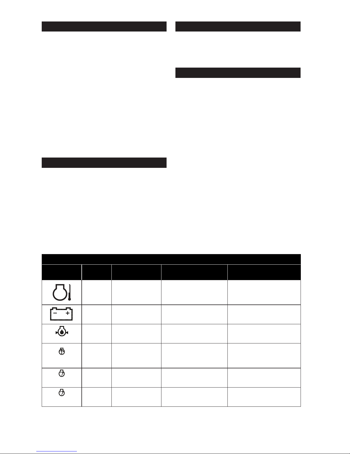
Repairing Minor Faults - MODYS Alarms and Faults
Pictograms
Color of
LED
Type of Fault Issue Possible Solution
Red
Engine
temperature
Shutdown: abnormal
engine temperature
Allow generator to cool
down and check air
cleaner and vents on
enclosure.
Red
Battery or
charging
alternator
Problem with alternator
charge output or weak
battery
Contact a Kohler
portable dealer.
Red
Oil pressure or
low oil level
Shutdown: incorrect oil
pressure or low oil level
Allow generator to cool
down, top up and check
oil level.
Red Non-starting fault
3 consecutive
unsuccessful starting
attempts
Check that generator has
been started according to
recommendations in this
manual.
Red Overspeed
Shutdown: generator
rotation speed
excessive
Contact a Kohler
portable dealer.
Flashing
Red
Speed too low
Shutdown: insufcient
generator rotation
speed
Contact a Kohler
portable dealer.
Page 12
12 34 590 01 Rev. AKohlerPower.com
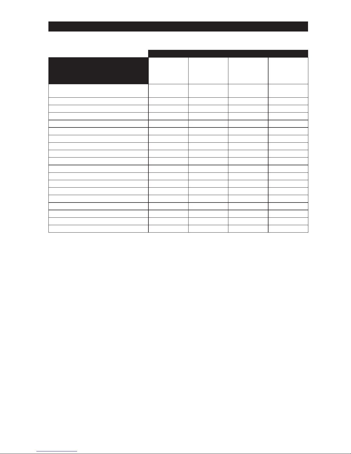
Troubleshooting
Do not attempt to service or replace major engine components, or any items that require special
timing or adjustment procedures. This work should be performed by a Kohler portable dealer.
Problem
Possible Cause
Engine Not
Starting/
Running
Abnormally
Engine
Stopped
No Electric
Current
Tripping of
Circuit
Breaker
Load connected to generating set
during start-up
●
Start and Stop control ON or OFF ●
Fuel valve closed ●
Fuel level too low ● ●
Unsuitable fuel ●
Oil level too low ● ●
Clogged air cleaner ●
Clogged fuel lter ●
Faulty starter battery. ●
Fuel supply blocked or leaking ● ●
Blocked ventilation inlets ●
Circuit protectors not actuated ●
Faulty appliance supply cord ●
Faulty electrical sockets ●
Faulty alternator ●
Device connected or faulty cord ●
Overload ●
Battery incorrectly connected ● ●
Faulty MODYS Fuses (J) ●
Page 13
13
34 590 01 Rev. A
KohlerPower.com
EN
Specications
Model PRO 12.3 EFI
Overall Dimensions (L x W x H)
35.2 in. (895 mm)
22.4 in. (570 mm)
30.3 in. (770 mm)
Dry Weight 306 lbs. (162 kg)
AC Rated Power 10,500 Watt
(120 Volts x 87.5 Amps)
(240 Volts x 43.8 Amps)
AC Maximum Power 12,300 Watt
(120 Volts x 102.5 Amps)
(240 Volts x 51.3 Amps)
Number of Phase Single Phase 240 Volts
DC Rated Power 100 Watt (12 Volts x 8.3 Amps)
Engine Specications
Bore 3.2 in. (80 mm)
Stroke 2.72 in. (69 mm)
Displacement 42.4 cu. in. (694 cc)
Oil Capacity (Rell) 1.7-2.0 U.S. qt. (1.6-1.9 L)
Maximum Angle of Operation (@ full oil level)* 25°
Run Time 10 hours (1/2 load)
Fuel See fuel section
Fuel Tank Capacity 8.7 U.S. gal. (33.0 L)
Spark Plug Gap 0.03 in. (0.76 mm)
*Exceeding maximum angle of operation may cause engine damage from insufcient lubrication.
Additional specication information can be found at KohlerPower.com.
Exhaust Emission Control System for model PRO 12.3 EFI is EM, O2S, ECM, MPI for U.S. EPA,
California, and Europe.
Page 14
14 34 590 01 Rev. AKohlerPower.com
Available Accessories
The most customizable generators the job site has ever seen.
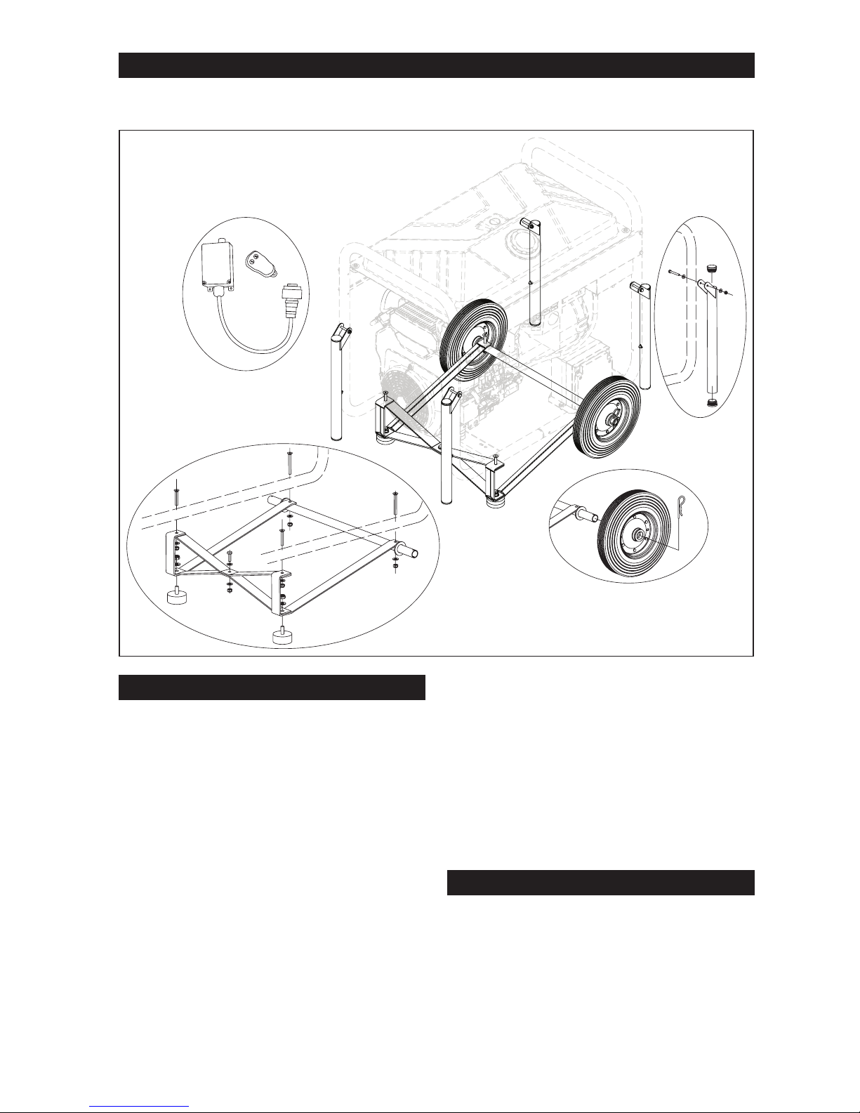
Mobility Kit
Install Mobility Kit
NOTE: Place blocks underneath to raise
generator to install wheels and legs.
NOTE: A clamping device or an assistant to
hold assembly while installing kit will
make process easier.
Mobility kit includes 2 solid rubber wheels, 2
legs, 4 handles and mounting hardware.
1. Align cross member holes at center and
place screw into hole. Insert washer and
thread nut to screw. Tighten loosely.
2. Assemble rubber bumpers to cross member
and axle brace. Insert washer and thread nut
to rubber bumper screw. Tighten loosely.
3. Position legs under frame. Install screws
through frame into cross member. Insert
washer and thread nut to screw. Tighten
loosely.
4. Align holes in axle to axle brace and frame.
Install screws through frame and axle. Insert
washer and thread nut to screw. Tighten
loosely.
5. Torque all nuts to 221 in. lb. (25 N·m).
6. Install wheels onto axle, push cotter pin into
hole in axle.
Install Handle:
1. Align handle with holes on frame.
2. Install screws with washers through leg.
Place another washer on other side and
thread nut on.
3. Tighten screws enough to allow handle to
move free.
Wireless Remote Kit
Wireless remote for starting or stopping
generator from a distance of up to 164 ft.
(50 m). No tools required for installation.
Wireless remote kit includes 1 wireless remote,
1 receiver which plugs into generator (AI) and
mounting hardware.
Page 15

15
34 590 01 Rev. A
KohlerPower.com
ESS
PRO 12.3 EFI
Manual del Usuario del Generador
IMPORTANTE: Lea atentamente todas las instrucciones y precauciones de seguridad
antes de poner el equipo en funcionamiento.
Asegúrese de que el generador está parado y nivelado antes de
realizar tareas de mantenimiento o reparación.
Registre la información del producto con el n de consultarla para realizar pedidos de piezas o para obtener la
cobertura de la garantía.
Especicación
Número de serie
Fecha de compra
Page 16

16 34 590 01 Rev. AKohlerPower.com
PRECAUCIÓN
Las descargas
eléctricas pueden
provocar lesiones.
No toque los
cables con el
generador en
funcionamiento.
No utilice nunca el generador
bajo la lluvia o la nieve.
No toque nunca el generador con
las manos mojadas, ya que podría
producirse una descarga eléctrica.
ADVERTENCIA
Las piezas rotatorias
pueden causar
lesiones graves.
Manténgase alejado
del generador
cuando esté en
funcionamiento.
Para evitar lesiones, mantenga
las manos, los pies, el pelo y la
ropa alejados de las piezas en
movimiento. No ponga nunca el
generador en funcionamiento
con las cubiertas,
revestimientos térmicos o
protecciones desmontados.
ADVERTENCIA
Los líquidos a alta
presión pueden
perforar la piel y
provocar lesiones
graves o la muerte.
No trabaje en
el sistema de
combustible sin
una formación
o el equipo
de seguridad
adecuado.
Las lesiones por perforación
de líquidos son muy tóxicas
y peligrosas. Si se produce
cualquier lesión, pida asistencia
sanitaria inmediatamente.
ADVERTENCIA
Las piezas calientes
pueden causar
quemaduras graves.
No toque el
generador durante
el funcionamiento
o inmediatamente
después de pararse.
No ponga nunca el generador
en funcionamiento con
las protecciones térmicas
desmontadas. No modique el
generador.
Coloque el generador en un lugar
donde no lo vayan a tocar los
peatones ni los niños.
Asegúrese de transportar el
generador por sus asas de
transporte únicamente.
ADVERTENCIA
Tensión peligrosa.
La retroalimenta-
ción al sistema de
suministro eléctrico
puede causar
daños materiales,
lesiones graves o
la muerte.
No conecte nunca un generador
portátil directamente a la toma
de un edicio.
Si el generador se va a utilizar
para corriente auxiliar, pida
a un electricista autorizado
y cualicado que instale un
conmutador de transferencia
automático para evitar la
interconexión accidental de las
fuentes de alimentación auxiliar
y normal.
ADVERTENCIA
Los arranques
accidentales pueden
provocar lesiones
graves o la muerte.
Antes de llevar a
cabo trabajos de
mantenimiento
o reparación,
desconecte y aísle
el cable de la bujía.
Antes de realizar cualquier
trabajo en el generador o en
el equipo, desactive el motor
como se indica a continuación:
1) Desconecte los cables de las
bujías. 2) Desconecte el cable del
polo negativo (-) de la batería.
No deje que los niños manejen
el generador.
ADVERTENCIA
La explosión del
carburante puede
provocar incendios y
quemaduras graves.
No llene el tanque
de combustible con
el generador en
funcionamiento o
caliente.
La gasolina es muy inamable
y sus vapores pueden hacer
explosión si se inaman. No
reposte nunca mientras fuma ni
cerca de una llama al descubierto.
Almacene la gasolina siempre
en contenedores homologados,
en locales desocupados, bien
ventilados y lejos de chispas o
llamas. El combustible derramado
podría inamarse si entra en
contacto con las piezas calientes
del motor o las chispas de
encendido. No utilice nunca
gasolina como agente de limpieza.
Precauciones de seguridad
PELIGRO: Un peligro que provoca la muerte, lesiones graves o daños materiales considerables.
ADVERTENCIA: Un peligro que podría provocar la muerte, lesiones graves o daños materiales considerables.
PRECAUCIÓN: Un peligro que podría provocar lesiones personales o daños materiales de poca gravedad.
NOTA: Se utiliza para noticar al personal sobre información importante para la instalación, el funcionamiento
o el mantenimiento.
Lea este manual con atención antes de utilizar esta máquina. Este manual deberá acompañar a la máquina en
caso de que esta se venda.
Page 17

17
34 590 01 Rev. A
KohlerPower.com
ESS
Advertencia: la Propuesta 65 de California
El escape de motor de este producto contiene sustancias químicas
identicadas por el Estado de California como causantes de cáncer,
defectos de nacimiento u otros daños genéticos.
Advertencia: la Propuesta 65 de California
Este producto contiene sustancias químicas identicadas por el Estado
de California como causantes de cáncer, defectos de nacimiento u
otros daños genéticos.
Etiquetas importantes en el generador
WARNING / ADVERTENCIA / AVERTISSEMENT
● Hot parts can cause severe burns. / Las piezas calientes pueden causar quemaduras graves. / Les pièces chaudes peuvent causer de graves brûlures.
● Do not touch generator while operating or just after stopping. / No toque el generador durante el funcionamiento o inmediatamente después de pararse. / Ne touchez pas le générateur pendant qu'il tourne ou si
vous venez tout juste de l'arrêter.
● Explosive Fuel can cause fires and severe burns. / La explosión del carburante puede provocar incendios y quemaduras graves. / Carburant explosif pouvant causer des incendies et des brûlures graves.
● Do not fill fuel tank while generator is hot or running. / No llene el tanque de combustible mientras el generador esté caliente o funcionando. / N'ajoutez pas de carburant si le moteur est chaud ou s'il tourne.
● Electrical shock can cause injury. / Las descargas eléctricas pueden provocar lesiones. / Les chocs électriques peuvent causer des blessures.
● Do not touch wires while generator is running. / No toque los cables con el generador en funcionamient. / Ne touchez pas aux le générateur pendant que le moteur tourne.
● Do not connect generator to a building's electrical system unless using an isolation (transfer) switch installed by a certified, licensed electrician. / No conecte el generador al sistema eléctrico de un edificio a menos
que use un aislamiento (transferencia) interruptor instalado por un electricista certificado y certificado. / Ne branchez pas le générateur dans le système électrique d’un bâtiment sauf si un commutateur-converteur
a été installé par un électricien agréé et compétent.
Page 18

18 34 590 01 Rev. AKohlerPower.com
W
Z
AG
AF
AE
AD
AB
AC
AA
V
U
C
B
F
T
Y
S
L
M N
R
Q
P
AH
AH
X
A
K
D
H
I
F
O
J
E
G
A Medidor de horas B MODYS C Luz piloto D Luz MIL
E Interruptor de carga F Protector de circuitos G Receptáculo GFCI H
Receptáculo de CC
de 12V
I Terminal de masa J Fusible K Ralentí automático L
Tomacorriente eléctrico
de 240/120V/50A
M
Tomacorriente eléctrico
de 240/120V/30A
N
Tomacorriente eléctrico
de 120V/30A
O
Tapón del tanque de
combustible
P Válvula de combustible
Q Filtro de combustible R Fusibles del motor S
Batería del motor de
arranque
T Varilla de nivel
U
Tapón de drenaje del
aceite
V Filtro de aceite W
Módulo de la bomba
de combustible
X Bujía
Y
Tapón de llenado de
aceite
Z
Soporte del ltro de
aire
AA Filtro de papel AB Preltro
AC Sello de goma AD Tapa del ltro AE Tuerca de mariposa AF
Rueda del ltro de aire
AG Tapa del ltro de aire AH
Exclusivo ltro
de combustible EFI
AI Conectar Wireless AJ
Botón de diagnóstico
AJ
AI
Page 19

19
34 590 01 Rev. A
KohlerPower.com
ESS
Lista de control previa al arranque
1. Asegúrese de que el generador esté al menos a 1
m (3,3 ft) del edicio o de cualquier otro equipo y
no esté tapado con ningún material.
2. Consulte todas las etiquetas de advertencia antes
de poner en marcha.
3. Comprobar el nivel de aceite. Añada aceite si está
bajo. No rellene por encima del límite.
4. Compruebe el nivel de combustible. Añada
combustible si está bajo. Deje de rellenar cuando el
indicador haya alcanzado el nivel F (lleno).
Compruebe si los componentes y las tuberías del
sistema de combustible presentan alguna fuga. No
reposte nunca con la unidad en funcionamiento.
5. Compruebe la batería del motor de arranque (S).
6. Conecte a masa el generador.
7. Verique que los componentes del ltro de aire y
todas las entradas de aire están libres de
obstrucciones, y que las cubiertas y protecciones
del equipo están en su sitio y bien sujetas.
8. Asegúrese de que no haya dispositivos eléctricos
(carga) conectados al generador.
Arranque
ADVERTENCIA
Las piezas rotatorias pueden causar
lesiones graves.
Manténgase alejado del generador
cuando esté en funcionamiento.
Para evitar lesiones, mantenga las manos, los
pies, el pelo y la ropa alejados de las piezas en
movimiento. No ponga nunca el generador en
funcionamiento con las cubiertas, revestimientos
térmicos o protecciones desmontados.
NOTA: El interruptor de ralentí automático (K) debe
estar en la posición OFF cuando se utilicen
dispositivos eléctricos que precisen una
elevada corriente de arranque, como un
compresor o una bomba sumergible. El
ralentí automático (K) controla la velocidad
del motor según la carga conectada. Los
resultados son un mejor consumo de
combustible y menos ruido.
NOTA: MODYS (B) efectúa automáticamente 5
intentos de arranque.
1. Gire el interruptor de carga (E) de CA a la posición
OFF.
2. Gire la válvula de combustible (P) a ON.
3. Gire la llave de MODYS (B) a la posición ON.
4. Presione el botón de ARRANQUE de MODYS (B).
5. Pruebe los receptáculos GFCI (G).
Arranque en tiempo frío
1. Utilice el aceite apropiado para la temperatura
prevista.
2. Desconecte todas las posibles cargas externas.
3. Use combustible de grado invierno reciente. El
combustible de grado invierno tiene una mayor
volatilidad que mejora el arranque.
Funcionamiento
ADVERTENCIA
Tensión peligrosa.
La retroalimentación al sistema de
suministro eléctrico puede causar
daños materiales, lesiones graves o
la muerte.
No conecte nunca un generador portátil
directamente a la toma de un edicio.
Si el generador se va a utilizar para corriente
auxiliar, pida a un electricista autorizado
y cualicado que instale un conmutador
de transferencia automático para evitar la
interconexión accidental de las fuentes de
alimentación auxiliar y normal.
Cuando la velocidad de operación del generador se
haya estabilizado (aproximadamente 3 minutos):
1. Verique que los interruptores de carga (E) estén
oprimidos. Presione si es necesario.
2. Conecte los aparatos que se vayan a utilizar a los
tomacorrientes eléctricos (G, L, M y N) del
generador.
3. El medidor de horas (A) muestra la cantidad de
horas que ha funcionado el generador.
Ángulo de funcionamiento
No haga funcionar el motor si supera el ángulo
máximo de funcionamiento, consulte la tabla de
especicaciones. El motor puede dañarse como
resultado de una lubricación insuciente.
Page 20

20 34 590 01 Rev. AKohlerPower.com
Selección del cable
Tipo de
tomacorriente del
generador
10 A 16 A 32 A
Sección transversal
del cable
recomendada
mm
2
AWG
mm
2
AWG
mm
2
AWG
Longitud
del cable
que se
utilizó
0 a
50 m
4 10 6 9 10 7
51 a
100 m
10 7 10 7 25 3
101 a
150 m
1
10 7 16 5 35 2
1
La longitud de este cable es la máxima permitida
y no se debe exceder.
Método de instalación = cables en el canal o en
la tablilla sin perforaciones/Caída permitida en
voltaje = 5%/Conductores multinúcleo/Tipo de cable
PVC 70°C (por ejemplo, H07RNF)/Temperatura
ambiente = 86° F (30° C).
Instrucciones de mantenimiento
ADVERTENCIA
Antes de realizar cualquier trabajo en el generador
o en el equipo, desactive el motor como se indica a
continuación: 1) Desconecte los cables de las bujías.
2) Desconecte el cable del polo negativo (–) de la batería.
No deje que los niños manejen el generador.
Los arranques accidentales pueden
provocar lesiones graves o la muerte.
Antes de llevar a cabo trabajos
de mantenimiento o reparación,
desconecte y aísle el cable de la bujía.
La seguridad es una obligación del propietario. La inspección, el ajuste y la lubricación de forma periódica
mantendrán su generador en el estado más seguro y eciente posible. Los puntos más importantes de
inspección, ajuste y lubricación del generador se explican en las siguientes páginas.
Programa de mantenimiento
Una vez al año o después de las primeras 25 horas
1
● Realice el mantenimiento/sustitución del preltro (si está incluido).
Una vez al año o cada 100 horas
1
● Cambie el aceite.
● Cambie el elemento ltrante (AA).
● Quite y limpie los revestimientos y las zonas de refrigeración.
Cada 200 horas
1
● Cambie el exclusivo ltro de combustible de Inyección electrónica de combustible (EFI).
Una vez al año o cada 200 horas
1
● Cambie el aceite y el ltro (V).
Una vez al año o cada 500 horas
1
● Cambie las bujías (X) y ajuste la separación entre electrodos.
1
Estas operaciones de mantenimiento deberán ejecutarse con mayor frecuencia en ambientes muy
polvorientos o sucios.
Ralentí automático
NOTA: Ralentí automático sólo funcionará cuando la
unidad está en función de 120V.
Posición ON. Cuando el interruptor de ralentí
automático (K) está en la posición ON, el ralentí
automático (K) controla la velocidad del motor de
acuerdo con la carga conectada. Los resultados son
un mejor consumo de combustible y menos ruido.
Posición OFF. Cuando el interruptor de ralentí
automático (K) está en la posición OFF, el motor
funciona al nivel nominal de rpm (3.600 rpm), haya o
no una carga conectada
NOTA: Gire ralentí automático en OFF cuando la
unidad está utilizando la conguración de 240V.
Parada
1. Desconecte los dispositivos eléctricos y deje que el
motor funcione sin ninguna carga durante 1-2
minutos.
2. Gire la llave de MODYS (B) a la posición OFF
(el generador se para).
3. Cierre la válvula de combustible (P).
Velocidad del motor
NOTA: No altere los ajustes del regulador para
aumentar la velocidad máxima del motor. El
exceso de velocidad es peligroso y anulará
la garantía.
Page 21

21
34 590 01 Rev. A
KohlerPower.com
ESS
Recomendaciones de lubricante
Recomendamos el uso de un aceite de Kohler para
obtener un mejor rendimiento. También se puede
utilizar otro aceite detergente de alta calidad API
(American Petroleum Institute) SJ o superior, incluidos
los aceites sintéticos. Seleccione la viscosidad
en función de la temperatura del aire durante el
funcionamiento como se muestra en la tabla que
aparece a continuación.
°F -20 020324060
50 80 100
°C -30 -20 -10 0 10 20 30 40
5W-30
10W-30
SAE 30
Comprobación del nivel de aceite
NOTA: Para evitar las averías y el desgaste
excesivo del motor, no ponga nunca el motor
en funcionamiento con un nivel de aceite
inferior o superior al indicador de nivel de
funcionamiento de la varilla (T).
Asegúrese de que el motor esté frío. Limpie los
residuos del área de la varilla de nivel.
1. Extraiga la varilla de nivel (T); limpie el exceso de
aceite. Introduzca de nuevo la varilla de nivel (T) en
el tubo y presione completamente hacia abajo.
2. Saque la varilla (T) y compruebe el nivel de aceite.
El nivel debe situarse en la parte superior de la
varilla de nivel (T).
3. Si el indicador muestra poco nivel de aceite, añada
aceite hasta la parte superior de la marca del
indicador.
4. Instale de nuevo y je la varilla de nivel (T).
Cambio del aceite y el ltro
Cambie el aceite con el motor caliente.
1. Limpie el área que rodea la varilla de nivel (T) y el
tapón de drenaje (U). Retire el tapón de drenaje (U)
y la varilla de nivel (T). Deje que el aceite drene
completamente.
2. Limpie el área que rodea el ltro (V). Coloque un
envase debajo del ltro para recoger el aceite y
extraiga el ltro. Limpie la supercie de montaje.
Vuelva a instalar el tapón de drenaje del aceite (U).
Aplique un par de apriete de 13,6 Nm (10 ft lb).
3. Coloque un ltro nuevo con el extremo abierto
hacia arriba en una bandeja. Vierta aceite nuevo
hasta que alcance la parte inferior de los tornillos.
Espere 2 minutos hasta que el material del ltro
absorba el aceite.
4. Aplique una película na de aceite limpio a la junta
de goma del nuevo ltro.
5. Consulte las instrucciones sobre el ltro del aceite
(V) para una instalación correcta.
6. Llene el cárter con aceite nuevo. El nivel debe
situarse en la parte superior de la varilla de nivel
(T).
7. Vuelva a instalar la varilla (T) y apriete bien.
8. Arranque el motor y compruebe si hay fugas de
aceite. Detenga el motor y repare las fugas.
Compruebe de nuevo el nivel de aceite.
9. Deseche el aceite usado y el ltro en conformidad
con las normativas locales.
Oil Sentry™ (si está incluido)
Este interruptor está diseñado para evitar que el motor
arranque con poco aceite o ninguno. El sistema Oil
Sentry™ apagará el motor en marcha.
Recomendaciones de combustible
ADVERTENCIA
La explosión del carburante puede
provocar incendios y quemaduras graves.
No llene el tanque de combustible con el
generador en funcionamiento o caliente.
La gasolina es muy inamable y sus vapores
pueden hacer explosión si se inaman. Almacene
la gasolina siempre en contenedores homologados,
en locales desocupados, bien ventilados y lejos de
chispas o llamas. El combustible derramado podría
inamarse si entra en contacto con las piezas
calientes del motor o las chispas de encendido. No
utilice nunca gasolina como agente de limpieza.
NOTA: E15, E20 y E85 are NO están autorizados y
NO deben utilizarse; la garantía no cubre los
efectos producidos por el uso de
combustible antiguo, pasado o contaminado.
El combustible debe cumplir con los siguientes requisitos:
● Gasolina limpia, fresca y sin plomo.
● Octanaje de 87 (R+M)/2 o superior.
● El “Research Octane Number” (RON) deberá ser
de 90 octanos como mínimo.
● Se autoriza el empleo de gasolina de hasta un
volumen máximo del 10% de alcohol etílico y el
90% sin plomo.
● Se autorizan las mezclas de metil-ter-butil-éter
(MTBE) y gasolina sin plomo (hasta un máximo del
15% de MTBE en volumen).
● No añada aceite a la gasolina.
● No llene el tanque de combustible por encima del
límite.
● No utilice gasolina con más de 30 días de
antigüedad.
Compruebe el nivel de combustible.
ADVERTENCIA
La explosión del carburante puede
provocar incendios y quemaduras graves.
No llene el tanque de combustible con el
generador en funcionamiento o caliente.
La gasolina es muy inamable y sus vapores
pueden hacer explosión si se inaman. Almacene
la gasolina siempre en contenedores homologados,
en locales desocupados, bien ventilados y lejos de
chispas o llamas. El combustible derramado podría
inamarse si entra en contacto con las piezas
calientes del motor o las chispas de encendido. No
utilice nunca gasolina como agente de limpieza.
Page 22

22 34 590 01 Rev. AKohlerPower.com
2. Coloque la bujía en el cabezal del cilindro.
3. Apriete la bujía (X) a 27 Nm (20 ft lb).
Sustitución de fusibles del motor
Este motor lleva tres (3) fusibles de automoción de
tipo plano (R). Los fusibles de repuesto (R) deben
tener la misma intensidad que el fusible fundido.
Utilice el siguiente cuadro de fusibles para encontrar
el fusible correcto (R).
Color del hilo
Intensidad del
fusible
2 cables rojos lisos
Fusible de 10
amperios
1 cable rojo con rayas negras
1 cable rojo con rayas blancas
Fusible de 10
amperios
2 cables morados
Fusible de 30
amperios
Filtro de aire
NOTA: El funcionamiento del motor con
componentes del ltro de aire sueltos o
dañados puede causar daños y desgaste
prematuro. Sustituya todos los componentes
doblados o dañados.
NOTA: El papel ltrante (AA) no puede expulsarse
con aire comprimido.
Aoje la rueda (AF) y extraiga la tapa del ltro de aire
(AG).
Preltro (AB):
1. Extraiga el preltro (AB) del papel ltrante (AA).
2. Sustituya o lave el preltro (AB) con agua templada
y detergente. Aclárelo y déjelo secar al aire.
3. Engrase el preltro (AB) con aceite nuevo y escurra
el exceso de aceite.
4. Vuelva a colocar el preltro (AB) sobre el papel
ltrante (AA).
Elemento de papel (AA):
1. Limpie el área que rodea al elemento (AA). Retire
la tuerca de mariposa (AE), la tapa del ltro (AD) y
el ltro de papel (AA) con el preltro (AB).
2. Separe el preltro (AB) del elemento ltrante (AA),
limpie el preltro (AB) y sustituya el elemento
ltrante (AA).
3. Compruebe el estado de la goma (AC) y cámbiela
si es necesario.
4. Instale el nuevo ltro de papel (AA) en la base (Z),
instale el preltro (AB) sobre el ltro de papel (AA),
vuelva a instalar la tapa del ltro (AD) y sujétela
con una tuerca de mariposa (AE).
Vuelva a instalar la tapa del ltro de aire (AG) y
sujétela con la rueda (AF).
Tubo del respirador
Asegúrese de que ambos extremos del respirador
están conectados adecuadamente.
Verique el nivel de combustible visualmente. Si es
necesario, rellene.
1. Desenrosque el tapón del tanque de combustible
(O).
2. Llene el tanque de combustible con un embudo,
teniendo cuidado de no derramarlo. No llene el
tanque por encima del límite (no debe haber nada
de combustible en el cuello de llenado).
3. Vuelva a enroscar el tapón del tanque de
combustible (O).
Filtro de combustible
1. Abra el tapón del tanque de combustible (O).
2. Quite el ltro de combustible (Q) del cuello del
tanque.
3. Limpie el ltro de combustible (Q) con un disolvente
incombustible o que tenga un alto punto de
inamabilidad. Séquelo totalmente. Cambie en
caso necesario.
4. Vuelva a instalar el ltro de combustible (Q).
5. Vuelva a instalar el tapón del tanque de combustible
(O).
Sistema de inyección electrónica de
combustible (EFI)
EFI es un sistema de gestión de combustible
controlado electrónicamente que es monitorizado por
una Unidad de Control Electrónica (UCE). Una luz
indicadora de fallo (MIL) se iluminará si se detectan
problemas o fallos. Se necesita el mantenimiento por
un distribuidor móvil de Kohler.
Tubería de combustible
En los motores Kohler Co. equipados con un sistema
EFI debe instalarse una tubería de combustible de alta
presión que cumpla con las normas del SAE R9.
Componentes del sistema de combustible
Los componentes de alta presión en el módulo de
la bomba de combustible (W) no se pueden reparar.
Los motores están equipados con un ltro de
combustible EFI especial (AH). Consulte el Programa
de mantenimiento.
Bujías
PRECAUCIÓN
Las descargas eléctricas pueden
provocar lesiones.
No toque los cables con el generador
en funcionamiento.
No utilice nunca el generador bajo la lluvia o la nieve.
No toque nunca el generador con las manos mojadas,
ya que podría producirse una descarga eléctrica.
Limpie el rebaje de la bujía. Extraiga la bujía y
sustitúyala.
1. Compruebe la separación de electrodos con una
galga de espesores. Para ajustar la separación,
consulte la tabla de especicaciones de ajuste.
Page 23

23
34 590 01 Rev. A
KohlerPower.com
ESS
Refrigeración por aire
ADVERTENCIA
Las piezas calientes pueden causar
quemaduras graves.
No toque el generador durante el
funcionamiento o inmediatamente
después de pararse.
No ponga nunca el generador en funcionamiento
con las protecciones térmicas desmontadas. No
modique el generador.
Coloque el generador en un lugar donde no lo
vayan a tocar los peatones ni los niños.
Asegúrese de transportar el generador por sus
asas de transporte únicamente.
Es esencial una refrigeración adecuada. Para evitar
el recalentamiento, asegúrese de que las zonas de
entrada y salida de refrigeración por aire estén limpias
y libres de obstrucciones. Evite rociar agua al haz de
cables o a cualquier componente eléctrico. Consulte
el Programa de mantenimiento.
Terminal de masa
El terminal de masa (I) conecta el cable de masa para
evitar descargas eléctricas. Cuando el dispositivo
eléctrico esté conectado a masa, asegúrese de
conectar a masa también el generador.
Conecte a masa el generador: conecte un cable de
cobre de 6 AWG (10 mm2) a la conexión a masa del
generador y a una pica de tierra de acero galvanizado
(no incluida) introducida 1 m (3,3 ft) en el suelo.
Conexión de corriente alterna (CA)
NOTA: Asegúrese de que todos los dispositivos
eléctricos, incluidos los cables y enchufe de
conexión, estén en buenas condiciones
antes de conectarlos al generador.
NOTA: Asegúrese de que la carga total esté dentro
de los límites de salida nominal del generador.
NOTA: Asegúrese de que la corriente de carga del
receptáculo esté dentro de los límites de
corriente nominal del receptáculo.
1. Arranque el motor.
2. Asegúrese de que la luz piloto de CA (C) esté
encendida.
3. Enchufe en el receptáculo de CA (G, L, M o N).
4. Encienda cualquier dispositivo eléctrico.
Potencia nominal de CA
La potencia nominal de CA es la cantidad de potencia
máxima que puede soportar el generador.
Potencia máxima de CA
La potencia máxima de CA es una potencia adicional
producida momentáneamente por el generador para
ayudar a poner en marcha dispositivos eléctricos que
requieren una potencia superior a la potencia nominal
del generador.
Receptáculo GFCI
PRECAUCIÓN
Las descargas eléctricas pueden
provocar lesiones.
No toque los cables con el generador
en funcionamiento.
No utilice nunca el generador bajo la lluvia o la nieve.
No toque nunca el generador con las manos mojadas,
ya que podría producirse una descarga eléctrica.
Con el n de reducir la posibilidad de descarga eléctrica:
1. No intente operar el equipo si el botón RESET del
interruptor del circuito de fallos de conexión a tierra
(GFCI) salta repentinamente de forma repetida
durante el uso.
2. Recuerde que sólo los receptáculos con la etiqueta
GFCI están protegidos por un interruptor del
circuito de fallos de conexión a tierra.
El interruptor del circuito de fallos de conexión a
tierra (GFCI) interrumpe el paso de corriente a los
receptáculos protegidos (G) si se detecta un fallo
de conexión a tierra (escape eléctrico). Si el botón
RESET salta hacia fuera, es posible que el equipo
enchufado al receptáculo (G) esté defectuoso. Si
esto ocurre, examine con atención el equipo. Si el
equipo parece estar en buenas condiciones, pulse
rmemente el botón RESET hasta oír un chasquido.
De esta forma se restablecerá la corriente. Si el
botón RESET vuelve a saltar, desenchufe el equipo
inmediatamente. Póngase en contacto con un
distribuidor móvil de Kohler antes de volver a utilizarlo.
Prueba del receptáculo GFCI
1. Ponga en marcha el generador.
2. Pulse el botón TEST; si funciona correctamente,
el botón RESET deberá saltar hacia fuera,
interrumpiendo la corriente enviada a la salida.
3. Si el funcionamiento del GFCI es correcto, presione
el botón RESET hacia adentro. Si el GFCI no
funciona correctamente, póngase en contacto con
un distribuidor móvil de Kohler.
Page 24

24 34 590 01 Rev. AKohlerPower.com
Sobrecarga (capacidad del generador)
No supere nunca la carga nominal del generador
(en amperios y/o vatios) cuando este se encuentre
en funcionamiento continuamente. Consulte la salida
nominal en la tabla de especicaciones.
Antes de conectar y utilizar el generador, calcule la
potencia eléctrica que requieren los aparatos eléctricos
(en vatios). Esta especicación de la potencia eléctrica
gura normalmente en la etiqueta del fabricante en
bombillas, aparatos eléctricos, motores, etc. La suma
total requerida por estos aparatos no debe superar la
potencia nominal del generador.
Los protectores de circuitos (F) y el interruptor de
carga (E) detendrán le energía de los receptáculos
protegidos (G, H, L, M o N) cuando se detecte la
sobrecarga de un dispositivo eléctrico conectado o
cuando el voltaje de salida de la CA se eleve para
proteger al generador y a cualquier dispositivo
eléctrico conectado.
Cuando ocurre una sobrecarga y se interrumpe la
generación de corriente, proceda del siguiente modo:
1. Apague todos los dispositivos eléctricos
conectados y pare el generador.
2. Reduzca el vataje total de los dispositivos
eléctricos conectados, dentro de los límites de
aplicación.
3. Compruebe si existe alguna obstrucción en las
zonas de entrada y salida de refrigeración por aire
y en torno a la unidad de control. Si encuentra
alguna obstrucción, elimínela.
4. Después de la comprobación, vuelva a arrancar el
generador.
Carga de baterías por medio del receptáculo de CC
PRECAUCIÓN
Las descargas eléctricas pueden
provocar lesiones.
No toque los cables con el generador
en funcionamiento.
No utilice nunca el generador bajo la lluvia o la nieve.
No toque nunca el generador con las manos mojadas,
ya que podría producirse una descarga eléctrica.
NOTA: Esta sección se reere a la carga de
baterías de 12 V en otros equipos, como
vehículos de motor o vehículos todoterreno.
No es posible el arranque con pinzas.
NOTA: Siga los procedimientos de seguridad
cuando manipule baterías con el n de evitar
los daños en los componentes eléctricos y la
explosión de las baterías. Consulte la cha
de datos de seguridad del fabricante de la
batería acerca de los riesgos de seguridad
del trabajo con baterías. Consulte las
instrucciones del fabricante de la batería
acerca de los procedimientos de carga/
mantenimiento de la batería.
NOTA: La tensión nominal de CC del generador es
de 12 V. El protector de circuitos de CC (F)
se apagará automáticamente si la corriente
supera el valor nominal durante la carga de
la batería. Ponga en marcha primero el
generador y luego conecte el generador a la
batería para cargarla. Antes de poner en
marcha para cargar la batería, asegúrese de
que el protector de circuitos de CC (F) se
encuentre en la posición RESET. Si el
protector de circuitos de CC (F) se vuelve a
apagar, deje de cargar la batería
inmediatamente y póngase en contacto con
un distribuidor móvil de Kohler.
NOTA: No conecte una batería regulada por válvula.
Para cargar una batería regulada por válvula
se necesita un cargador de batería especial
(tensión constante).
NOTA: No conecte ninguna carga a la batería ni
utilice el motor de arranque durante la carga.
Esto provoca el paso de una corriente alta a
través del generador que quemaría la
bobina.
NOTA: Antes de cargar la batería, retire los cables
positivo y negativo de la batería.
1. Ponga en marcha el generador.
2. Presione el protector de circuitos de CC (F).
3. Conecte el cable rojo del cargador de batería al
terminal positivo de la batería. Conecte el cable
negro del cargador de batería al terminal negativo
de la batería. No invierta estas posiciones. Conecte
el cable al receptáculo de CC (H).
Límites de alimentación de CC (sólo carga de
baterías de 12 V):
Esta fuente de alimentación está diseñada para cargar
baterías de hasta 40 Ah semidescargadas. No cargue
baterías de capacidad superior a 40 Ah.
Batería de 12 V:
El tiempo necesario para recargar una batería
depende del nivel de descarga de la batería. Cuando
la gravedad especíca de la batería alcanza de 1,26
a 1,28, la carga ha concluido. Durante la carga,
compruebe la gravedad especíca de la batería una
vez cada hora. El tiempo medio de carga de una
batería de 40 Ah semidescargada es de unas 5 horas.
Asegúrese de comprobar el nivel de líquido de la
batería antes de cargar.
Page 25

25
34 590 01 Rev. A
KohlerPower.com
ESS
Protector de circuitos de CC
NOTA: Reduzca la carga del dispositivo eléctrico
conectado, por debajo de la salida nominal
especicada del generador, si el protector de
circuitos de CC (F) se apaga. Si el protector
de circuitos de CC (F) se vuelve a apagar,
deje de usar el dispositivo inmediatamente y
póngase en contacto con un distribuidor
móvil de Kohler.
El botón del protector de circuitos de CC (F) saltará
hacia afuera, interrumpiendo el paso de corriente
del receptáculo de CC (H) cuando el dispositivo
electrónico conectado al generador funcione con una
corriente superior al valor nominal. Para usar este
equipo de nuevo, presione el botón del protector de
circuitos de CC (F).
Batería del motor de arranque
Debido a que la batería (S) no requiere
mantenimiento, verique simplemente la condición y
el ajuste de las conexiones y su limpieza general.
Interruptor de carga
El circuito eléctrico del conjunto del generador
está protegido por uno o más interruptores
magnetotérmicos, diferenciales o de corte automático.
Si ocurre una sobrecarga y/o un corto circuito, es
posible que se suspenda el suministro de energía
eléctrica.
Si es necesario, reemplace el interruptor de carga
(E) del conjunto generador con otros interruptores de
potencial nominal y especicaciones idénticas.
Limpieza del conjunto del generador
1. Quite el polvo y los residuos que hay alrededor del
silenciador del escape.
2. Limpie el generador y, en especial, las entradas y
las salidas de aire del motor y el alternador con un
trapo y un cepillo.
3. Revise las condiciones generales del generador y,
si es necesario, reemplace cualquier pieza
defectuosa.
Sustitución de los fusibles protectores
NOTA: Respete las especicaciones técnicas de los
fusibles. El uso de un fusible incorrecto
puede dañar el generador.
Sustituya los fusibles (J) en caso de fallo por
sobrecorriente. Antes de sustituir un fusible (J)
gastado por otro nuevo, contacte siempre con un
distribuidor móvil de Kohler para averiguar la causa
del fallo y la sobrecorriente.
1. Gire la llave de MODYS (B) a la posición OFF. El
generador se para.
2. Desenrosque el portafusibles de 12 V para MODYS
(B) y la iluminación y el portafusibles de 240 V para
MODYS (B) y el contador de horas de
funcionamiento.
3. Compruebe visualmente el estado de los dos
fusibles (J).
4. Sustituya los fusibles (J) gastados por otros nuevos
de tipo 5 x 20 con una intensidad de 2 A.
5. Vuelva a enroscar los dos portafusibles.
Transportación del generador
Antes de transportar el generador, verique que los
pernos estén bien apretados, cierre la válvula del
combustible (P) y desconecte la batería del motor de
arranque. Se debe transportar el generador en su
posición de funcionamiento normal, nunca la coloque
sobre su costado. Asegúrese de que el lugar donde
guardará y usará el generador se haya preparado
cuidadosamente con anticipación.
Reparaciones/Piezas de recambio
Recomendamos que utilice un distribuidor móvil de
Kohler para el mantenimiento, la reparación o la
sustitución de piezas del motor. Para encontrar un
distribuidor móvil de Kohler, visite KohlerPower.com o
llame al 1-800-544-2444 (EE. UU. y Canadá).
Almacenamiento
El almacenamiento de larga duración de su generador
requiere algunos procedimientos preventivos para
protegerlo del deterioro.
NOTA: No conecte con ningún dispositivo eléctrico
(funcionamiento sin carga).
Si el motor no se pone en funcionamiento durante 2
meses o más, siga el procedimiento siguiente.
1. Añada el tratamiento de combustible Kohler PRO
Series o equivalente al depósito de combustible.
Arranque el motor durante 2-3 minutos para que el
combustible se estabilice en el sistema de
combustible (la garantía no cubre los fallos
provocados por combustible sin tratar).
2. Cambie el aceite con el motor aún caliente.
Extraiga las bujías (X) y vierta aproximadamente
28 g (1 oz) de aceite de motor en los cilindros.
Sustituya las bujías (X) y arranque el motor
lentamente para distribuir el aceite.
3. Limpie el generador.
4. Almacene el generador en un lugar seco y bien
ventilado, con la tapa puesta. Asegúrese de no
tapar el generador hasta que el motor y el
silenciador/protector se hayan enfriado del todo. El
generador debe permanecer en la misma posición
que para el funcionamiento normal.
Page 26

26 34 590 01 Rev. AKohlerPower.com
Reparación de fallos menores - Alarmas y fallos de MODYS
Símbolos
Color
del LED
Tipo de fallo Problema Posible solución
Rojo Temperatura del motor
Apagar: Temperatura anormal
del motor
Deje que se enfríe el generador
y compruebe el ltro de aire y las
rejillas de ventilación en la carcasa.
Rojo
Batería o alternador
de carga
Problema con la salida de carga
del alternador o batería baja
Póngase en contacto con un
distribuidor móvil de Kohler.
Rojo
Presión del aceite o
nivel bajo de aceite
Apagar: presión incorrecta del
aceite o nivel bajo de aceite
Deje que se enfríe el generador
con la tapa superior abierta y
compruebe el nivel de aceite.
Rojo Fallo de arranque
3 intentos consecutivos de
arranque sin éxito
Compruebe que el generador se
ha arrancado de acuerdo con las
recomendaciones de este manual.
Rojo Exceso de velocidad
Apagar: velocidad de rotación
excesiva del generador
Póngase en contacto con un
distribuidor móvil de Kohler.
Rojo
parpadeante
Velocidad demasiado
baja
Apagar: velocidad insuciente
de rotación del generador
Póngase en contacto con un
distribuidor móvil de Kohler.
Localización de averías
No intente reparar o cambiar componentes principales del motor o cualquier elemento que requiera unos
procedimientos de ajuste o sincronización especiales. Este trabajo debe ser realizado por un distribuidor móvil de
Kohler.
Problema
Causa posible
El motor
no arranca/
funciona
anormalmente.
El motor
se paró
No hay
corriente
eléctrica
Desconexión
del interruptor
de carga
Carga conectada al conjunto del
generador durante el arranque
●
Control de arranque y paro en ON u OFF ●
Válvula de combustible cerrada ●
Nivel de combustible muy bajo ● ●
Combustible inadecuado ●
Nivel de aceite muy bajo ● ●
Filtro de aire obstruido ●
Filtro de combustible obstruido ●
Batería del motor de arranque
defectuosa.
●
Suministro de combustible bloqueado
o con fuga
● ●
Entradas de ventilación bloqueadas ●
Protectores de circuitos no activados ●
Cable de suministro de dispositivo
defectuoso
●
Tomacorrientes eléctricos defectuosos ●
Alternador defectuoso ●
Dispositivo conectado o cable
defectuoso
●
Sobrecarga ●
Batería conectada de manera incorrecta ● ●
Fusibles de MODYS averiados (J) ●
Page 27

27
34 590 01 Rev. A
KohlerPower.com
ESS
Especicaciones
Modelo PRO 12.3 EFI
Dimensiones totales
(Largo x Ancho x Alto)
895 mm (35,2 in)
570 mm (22,4 in)
770 mm (30,3 in)
Peso en seco 306 lbs. (162 kg)
Potencia nominal de CA 10.500 W
(120 voltios x 87,5 amperios)
(240 voltios x 43,8 amperios)
Potencia máxima de CA 12.300 W
(120 voltios x 102,5 amperios)
(240 voltios x 51,3 amperios)
Número de fases Monofásico 240 voltios
Potencia nominal de CC 100 W (12 voltios x 8.3 amperes)
Especicaciones del motor
Oricio 80 mm (3,2 in)
Carrera 69 mm (2,72 in)
Desplazamiento 694 cc (42,4 cu in)
Capacidad de aceite (rellenado) 1,6-1,9 l (1,7-2,0 U.S. qt.)
Ángulo de funcionamiento máximo
(con nivel máximo de aceite)*
25°
Tiempo de funcionamiento 10 horas (1/2 carga)
Combustible Véase la sección de combustible
Capacidad del tanque de combustible 33,0 L (8,7 U.S. gal)
Abertura de bujía 0,76 mm (0,03 in)
*Si se excede el ángulo máximo de funcionamiento puede dañarse el motor debido a lubricación insuciente.
Puede encontrar información adicional sobre las especicaciones en KohlerPower.com.
El sistema de control de emisiones de escape para los modelo PRO 12.3 EFI es EM, O2S, ECM y MPI para la
EPA estadounidense, California y Europa.
Page 28

28 34 590 01 Rev. AKohlerPower.com
Accesorios disponibles
Los generadores más adaptables al lugar de trabajo que se hayan visto jamás.
Kit de movilidad
Instalación del kit de movilidad
NOTA: Coloque unos bloques debajo del generador
para levantarlo e instalar las ruedas y las patas.
NOTA: Un dispositivo de sujeción o un ayudante que
sujete el conjunto durante la instalación del kit
facilitarán el proceso.
El kit de movilidad incluye 2 ruedas macizas de goma,
2 patas, 4 manivelas y los accesorios de montaje.
1. Alinee los oricios del travesaño en el centro e
introduzca el tornillo en el oricio. Inserte la
arandela y enrosque la tuerca en el tornillo. Apriete
de forma holgada.
2. Monte los topes de goma en el travesaño y el
tirante del eje. Inserte la arandela y enrosque la
tuerca en el tornillo del tope de goma. Apriete de
forma holgada.
3. Coloque las patas bajo el bastidor. Instale los
tornillos a través del bastidor en el travesaño.
Inserte la arandela y enrosque la tuerca en el
tornillo. Apriete de forma holgada.
4. Alinee los oricios del eje con el tirante del eje y el
bastidor. Instale los tornillos a través del bastidor y
el eje. Inserte la arandela y enrosque la tuerca en
el tornillo. Apriete de forma holgada.
5. Apriete todas las tuercas a 25 Nm (221 in lb).
6. Instale las ruedas en el eje y empuje el pasador de
chaveta en el agujero del eje.
Instalación de la manivela:
1. Alinee la manivela con los oricios del bastidor.
2. Fije cada pata con los tornillos con arandelas.
Coloque otra arandela al otro lado y enrosque la
tuerca.
3. Apriete los tornillos lo suciente para permitir que la
manivela se mueva.
Kit remoto inalámbrico
Control remoto inalámbrico para arrancar o detener
el generador desde una distancia de hasta 50 m
(164 ft.). No se requieren herramientas para la
instalación.
El Kit remoto inalámbrico incluye 1 control remoto
inalámbrico, 1 receptor que se conecta al generador
(AI) y los accesorios de montaje.
Page 29

29
34 590 01 Rév. A
KohlerPower.com
FRC
PRO 12.3 EFI
Manuel de l'utilisateur – Générateur
IMPORTANT : Lisez toutes les consignes et précautions de sécurité avant d'utiliser le
matériel.
Le générateur doit être arrêté et de niveau avant d'exécuter tout
travail de maintenance ou d'entretien.
Enregistrez les informations concernant le produit pour référence lors de la commande de pièces ou de demande
de couverture de garantie.
Spécications
Numéro de série
Date d'achat :
Page 30

30 34 590 01 Rév. AKohlerPower.com
ATTENTION
Les chocs
électriques peuvent
causer des
blessures.
Ne touchez pas aux
ls pendant que le
générateur tourne.
Ne laissez jamais tourner le
générateur sous la pluie ou la
neige.
Ne touchez jamais le générateur
avec les mains mouillées. Il y a
risque de choc électrique.
AVERTISSEMENT
Les pièces
tournantes peuvent
causer de graves
blessures.
Éloignez-vous du
générateur pendant
qu’il fonctionne.
Tenez vos mains, pieds, cheveux
et vêtements à l’écart de toutes
les pièces mobiles pour prévenir
les blessures. Ne faites jamais
fonctionner le générateur si des
couvercles, des enveloppes ou
des protections ont été enlevés.
AVERTISSEMENT
Des liquides à haute
pression peuvent
être nocifs pour la
peau et causer des
blessures graves
voire mortelles.
Ne travaillez pas
sur un circuit
d'alimentation
si vous n'avez
pas la formation
appropriée ou
l'équipement qui
convient.
Les blessures provoquées
par le liquide sont hautement
toxiques et dangereuses. En
cas de blessure, consultez
immédiatement un médecin.
AVERTISSEMENT
Les pièces chaudes
peuvent causer de
graves brûlures.
Ne touchez pas au
générateur pendant
qu’il tourne ou si
vous venez tout
juste de l’arrêter.
Ne faites jamais fonctionner
le générateur si des écrans
thermiques ou des protections
ont été enlevés. Ne modiez pas
le générateur.
Le générateur doit être installé
dans un endroit inaccessible par
les piétons ou les enfants.
Le générateur ne doit être porté
que par les poignées.
AVERTISSEMENT
Tension – Danger.
Un retour
d'alimentation
vers un système
utilitaire peut causer
des dommages
matériels, des
blessures graves
voire mortelles.
Ne branchez jamais un
générateur portable directement
dans une prise du bâtiment.
Si le générateur est utilisé en
mode veille, demandez à un
électricien agréé et compétent
d'installer un commutateurconverteur pour éviter une
interconnexion imprévue des
sources d'alimentation du mode
veille et du mode normal.
AVERTISSEMENT
Des démarrages
accidentels peuvent
causer des blessures
graves voire
mortelles.
Débranchez le(s)
câble(s) de bougie
et mettez-le(s) à
la masse avant
l'entretien.
Arrêtez le moteur avant
d'effectuer des travaux de
réparation et d'entretien du
générateur ou de l'équipement
en suivant les consignes
ci-dessous : 1) Débranchez
le(s) câble(s) de bougie. 2)
Débranchez le câble négatif (–)
de batterie de la batterie.
Ne laissez pas les enfants
utiliser le générateur.
AVERTISSEMENT
Carburant explosif
pouvant causer des
incendies et des
brûlures graves.
N'ajoutez pas de
carburant si le
générateur est
chaud ou s'il tourne.
L’essence est extrêmement
inammable et le contact de
ses vapeurs avec une source
d’allumage peut provoquer une
explosion. Ne faites jamais le plein
en fumant ou à côté d'une amme.
Entreposez l'essence dans des
récipients approuvés et dans des
bâtiments non occupés, à l'abri
des étincelles ou des ammes.
Des éclaboussures de carburant
peuvent s'enammer au contact
de pièces chaudes ou d'étincelles
provenant de l'allumage. N’utilisez
jamais d’essence comme agent
nettoyant.
Consignes de sécurité
DANGER : Un danger pouvant entraîner la mort, de graves blessures ou des dommages matériels.
AVERTISSEMENT : Un danger pouvant entraîner la mort, de graves blessures ou des dommages matériels.
ATTENTION Un danger pouvant entraîner des blessures légères ou des dommages matériels.
REMARQUE : Cette mention est utilisée pour attirer l'attention sur des détails importants concernant l'installation,
l'utilisation ou l'entretien.
Lisez ce manuel avec précaution avant d’utiliser cette machine. Ce manuel doit rester avec la machine si celle si
est vendue.
Page 31

31
34 590 01 Rév. A
KohlerPower.com
FRC
Californie Proposition 65 Avertissement
L'échappement de moteur émanant de ce produit comprend des
agents chimiques qui, selon l'État de Californie, sont la cause de
cancers, d'anomalies congénitales, ou d'autres lésions génésiques.
Californie Proposition 65 Avertissement
Ce produit comprend des agents chimiques qui, selon l'État de
Californie, sont la cause de cancers, d'anomalies congénitales ou
d'autres lésions génésiques.
Étiquettes importantes apposées sur le générateur
WARNING / ADVERTENCIA / AVERTISSEMENT
● Hot parts can cause severe burns. / Las piezas calientes pueden causar quemaduras graves. / Les pièces chaudes peuvent causer de graves brûlures.
● Do not touch generator while operating or just after stopping. / No toque el generador durante el funcionamiento o inmediatamente después de pararse. / Ne touchez pas le générateur pendant qu'il tourne ou si
vous venez tout juste de l'arrêter.
● Explosive Fuel can cause fires and severe burns. / La explosión del carburante puede provocar incendios y quemaduras graves. / Carburant explosif pouvant causer des incendies et des brûlures graves.
● Do not fill fuel tank while generator is hot or running. / No llene el tanque de combustible mientras el generador esté caliente o funcionando. / N'ajoutez pas de carburant si le moteur est chaud ou s'il tourne.
● Electrical shock can cause injury. / Las descargas eléctricas pueden provocar lesiones. / Les chocs électriques peuvent causer des blessures.
● Do not touch wires while generator is running. / No toque los cables con el generador en funcionamient. / Ne touchez pas aux le générateur pendant que le moteur tourne.
● Do not connect generator to a building's electrical system unless using an isolation (transfer) switch installed by a certified, licensed electrician. / No conecte el generador al sistema eléctrico de un edificio a menos
que use un aislamiento (transferencia) interruptor instalado por un electricista certificado y certificado. / Ne branchez pas le générateur dans le système électrique d’un bâtiment sauf si un commutateur-converteur
a été installé par un électricien agréé et compétent.
Page 32

32 34 590 01 Rév. AKohlerPower.com
W
Z
AG
AF
AE
AD
AB
AC
AA
V
U
C
B
F
T
Y
S
L
M N
R
Q
P
AH
AH
X
A
K
D
H
I
F
O
J
E
G
A
Horomètre
B
MODYS
C
Témoin pilote
D
Témoin d'anomalie
E
Disjoncteur
F
Dispositif de
protection du circuit
G
Prise GFCI
H
Prise 12 V CC
I
Borne de masse
J
Fusible
K
Ralenti
automatique
L
Prise électrique
240/120 V – 50A
M
Prise électrique
240/120 V – 30 A
N
Prise électrique
120 V/30 A
O
Bouchon du
réservoir de
carburant
P
Soupape de
carburant
Q
Filtre à carburant
R
Fusibles du moteur
S
Batterie de
démarreur
T
Jauge
U
Bouchon de
vidange d'huile
V
Filtre à huile
W
Module de pompe
à carburant
X
Bougie
Y
Bouchon de
remplissage d'huile
Z
Base du ltre à air
AA
Élément papier
AB
Préltre
AC
Joint en caoutchouc
AD
Couvercle de
l'élément
AE
Écrou à ailettes
AF
Bouton du ltre
à air
AG
Couvercle du ltre
à air
AH
Filtre à carburant
EFI unique
AI
Wireless
branchez
AJ
Bouton de
diagnostic
AJ
AI
Page 33

33
34 590 01 Rév. A
KohlerPower.com
FRC
Liste de vérication à utiliser avant le démarrage
1. Le générateur doit être à une distance de 1 m (3,3
pi) du bâtiment ou autre matériel et ne doit pas
recouvert.
2. Vériez toutes les étiquettes avant de commencer.
3. Vériez le niveau d'huile. Ajoutez de l'huile si le
niveau est bas. Ne remplissez pas trop le réservoir.
4. Vériez le niveau de carburant. Ajoutez du
carburant si le niveau est bas. Arrêtez le
remplissage quand le témoin atteint le niveau F
(plein). Recherchez la présence de fuites sur les
conduites et les composants du système
d'alimentation en carburant. Ne faites jamais le
plein pendant le fonctionnement de l'appareil.
5. Vériez la batterie du démarreur (S).
6. Générateur de masse.
7. Assurez-vous que le ltre à air et toutes les
admissions d'air ne sont pas bouchés, et que tous
les couvercles d'équipement et toutes les
protections sont en place et bien xés.
8. Assurez-vous que les dispositifs électriques
(charge) ne sont pas connectés au générateur.
Démarrage
AVERTISSEMENT
Les pièces tournantes peuvent causer
de graves blessures.
Éloignez-vous du générateur pendant
qu’il fonctionne.
Tenez vos mains, pieds, cheveux et vêtements à
l’écart de toutes les pièces mobiles pour prévenir
les blessures. Ne faites jamais fonctionner le
générateur si des couvercles, des enveloppes ou
des protections ont été enlevés.
REMARQUE : Le commutateur de ralenti
automatique (K) doit être en position
OFF lorsque des dispositifs
électriques connectés nécessitent un
fort courant de démarrage, comme un
compresseur ou une pompe
immergée. Le ralenti automatique (K)
contrôle le régime du moteur en
fonction de la charge connectée. Il en
résulte une réduction de la
consommation de carburant et une
diminution du bruit.
REMARQUE : MODYS (B) effectue automatiquement
5 tentatives de lancement.
1. Désactivez le disjoncteur CA (E) (OFF).
2. Activez la soupape de carburant (P) (ON).
3. Tournez la clé MODYS (B) en position ON.
4. Appuyez sur le bouton START (démarrer) sur
MODYS (B).
5. Vériez les prises GFCI (G).
Démarrage par temps froid
1. Utilisez l'huile correspondant aux températures d'air
prévues.
2. Éliminez toutes les charges externes.
3. Utilisez du carburant neuf destiné à une utilisation
hivernale. L'essence d'hiver possède une volatilité
supérieure qui facilite le démarrage.
Opération
AVERTISSEMENT
Tension – Danger.
Un retour d'alimentation vers un
système utilitaire peut causer des
dommages matériels, des blessures
graves voire mortelles.
Ne branchez jamais un générateur portable
directement dans une prise du bâtiment.
Si le générateur est utilisé en mode veille,
demandez à un électricien agréé et compétent
d'installer un commutateur-converteur pour
éviter une interconnexion imprévue des sources
d'alimentation du mode veille et du mode normal.
Lorsque le régime de fonctionnement du générateur
s'est stabilisé (après 3 minutes environ) :
1. Assurez-vous que les disjoncteurs (E) sont
enfoncés. Appuyez, le cas échéant.
2. Branchez les appareils à utilisez dans les prises
électriques (G, L, M et N) du générateur.
3. L'horomètre (A) indique le nombre d'heures de
fonctionnement du générateur.
Angle de fonctionnement
Ne poussez pas ce moteur au maximum de ses limites.
Voir le tableau des spécications. Le moteur pourrait être
endommagé en raison d'une lubrication insufsante.
Page 34

34 34 590 01 Rév. AKohlerPower.com
Sélection de câble
Type de prise de
générateur
10 A 16 A 32 A
Section
transversale
de câble
recommandée
mm
2
AWG
mm
2
AWG
mm
2
AWG
Longueur
de câble
utilisé
0 à
50 m
4 10 6 9 10 7
51 à
100 m
10 7 10 7 25 3
101 à
150 m
1
10 7 16 5 35 2
1
Cette longueur de câble représente la longueur
maximale autorisée. Elle ne doit en aucun cas être
dépassée.
Méthode d'installation=câbles sur chemin
ou tablette non percée/chute de tension
autorisée=5 %/Conducteurs multipolaires/Câble
type PVC 70 °C (ex. H07RNF)/Température
ambiante=30 °C (86 °F).
Consignes d'entretien
AVERTISSEMENT
Arrêtez le moteur avant d'effectuer des travaux
de réparation et d'entretien du générateur ou de
l'équipement en suivant les consignes ci-dessous : 1)
Débranchez le(s) câble(s) de bougie. 2) Débranchez le
câble négatif (–) de batterie de la batterie.
Ne laissez pas les enfants utiliser le générateur.
Des démarrages accidentels peuvent
causer des blessures graves voire
mortelles.
Débranchez le(s) câble(s) de bougie et
mettez-le(s) à la masse avant l'entretien.
Le propriétaire est responsable de la sécurité. Vériez, réglez et graissez périodiquement votre générateur an qu’il
reste dans le meilleur état possible et que la sécurité soit maintenue. Les points les plus importants de la vérication,
le réglage et le graissage sont expliqués dans les pages suivantes.
Programme d’entretien
Les 25 premières heures ou sur une base annuelle
1
● Entretenez/remplacez le préltre (le cas échéant).
Toutes les 100 heures ou sur une base annuelle
1
● Changez l'huile.
● Remplacez l'élément de ltre à air (AA).
● Retirez et nettoyez les enveloppes et les zones de refroidissement.
Toutes les 200 heures
1
● Remplacez le ltre à carburant de l'injection électronique de carburant (EFI).
Toutes les 200 heures ou sur une base annuelle
1
● Remplacez le ltre et l'huile (V).
Toutes les 500 heures ou sur une base annuelle
1
● Remplacez les bougies (X) et réglez l’écartement.
1
Effectuez ces procédures plus fréquemment en cas d'utilisation dans un environnement poussiéreux et sale.
Ralenti automatique
REMARQUE: Ralenti automatique ne de fonction
lorsque l'appareil est en fonction, 120V.
ON Position. Lorsque le commutateur de ralenti
automatique (K) est en position ON, il contrôle le
régime du moteur en fonction de la charge connectée.
Il en résulte une réduction de la consommation de
carburant et une diminution du bruit.
OFF Position. Lorsque le commutateur de ralenti
automatique (K) est en position OFF, le moteur tourne
à son régime nominal (3600 tr/min), peu importe si
une charge est raccordée.
REMARQUE: Tournez veille automatique sur OFF
lorsque l'appareil utilise la conguration de 240V.
Arrêt
1. Débranchez les dispositifs électriques et laissez le
moteur tourner sans charge pendant 1 à 2 minutes.
2. Tournez la clé MODYS (B) en position OFF (arrêt
du générateur).
3. Fermez la soupape de carburant (P).
Régime du moteur
REMARQUE : Ne modiez pas le limiteur de vitesse
pour augmenter le régime maximal du
moteur. La survitesse est dangereuse
et annule la garantie.
Page 35

35
34 590 01 Rév. A
KohlerPower.com
FRC
Recommandations relatives à l'huile
Pour un meilleur rendement, nous recommandons
les huiles Kohler. Utilisez les huiles détergentes de
qualité supérieure (y compris les huiles synthétiques)
de classe SJ ou supérieure de l’API. Choisissez la
viscosité en fonction de la température ambiante au
moment de l'utilisation, comme indiqué ci-dessous.
°F -20 020324060
50 80 100
°C -30 -20 -10 0 10 20 30 40
5W-30
10W-30
SAE 30
Contrôle du niveau d'huile
REMARQUE : Ne faites jamais tourner le moteur si le
niveau d'huile est trop haut ou trop bas
sur la jauge (T), ceci an d'éviter toute
usure ou endommagement du moteur.
Le moteur doit être froid. Nettoyez toutes traces de
débris sur les zones de la jauge.
1. Dévissez la jauge (T), essuyez-la. Réinsérez la jauge
(T) dans le tube en l'enfonçant complètement.
2. Dévissez la jauge (T), vériez le niveau d'huile. Le
niveau doit être en haut sur la jauge (T).
3. Si le niveau d'huile est bas, ajoutez de l'huile
jusqu'au repère supérieur.
4. Réinstallez et serrez la jauge (T).
Remplacement du ltre et de l'huile
Changez l’huile pendant que le moteur est encore
chaud.
1. Nettoyez la surface autour la jauge (T) et du bouchon
de vidange (U). Retirez le bouchon de vidange (U) et
la jauge (T). Évacuez entièrement l'huile.
2. Nettoyez la surface autour du ltre à huile (V).
Placez un récipient sous le ltre pour récupérer
l'huile et retirez le ltre. Nettoyez la surface de
montage. Réinstallez le bouchon de vidange (U).
Serrez au couple de 13,6 N.m (10 pi. lb).
3. Placez un nouveau ltre dans un bac étroit avec
l'extrémité ouverte vers le haut. Remplissez avec
de l'huile neuve jusqu'à ce qu'elle atteigne le bas
des lets. Attendez 2 minutes le temps que l'huile
soit absorbée par le ltre.
4. Appliquez une mince pellicule d'huile propre sur le
joint de caoutchouc du nouveau ltre.
5. Suivez les instructions relatives au ltre à huile (V)
pour une installation correcte.
6. Remplissez le carter avec de l'huile neuve. Le
niveau doit être en haut sur la jauge (T).
7. Remettez en place la jauge (T) et serrez fermement.
8. Faites démarrer le moteur et assurez-vous de
l'absence de fuites d'huile. Coupez le moteur et
rectiez le problème de fuite. Vériez de nouveau
le niveau d’huile.
9. Mettez au rebut l'huile et le ltre usés en respectant
les réglementations locales.
Oil Sentry™ (le cas échéant)
Ce commutateur est conçu pour éviter au moteur de
démarrer s'il n'y a pas d'huile ou si le niveau est bas.
Oil Sentry™ peut couper un moteur qui tourne.
Recommandations relatives au carburant
AVERTISSEMENT
Carburant explosif pouvant causer des
incendies et des brûlures graves.
N'ajoutez pas de carburant si le
générateur est chaud ou s'il tourne.
L’essence est extrêmement inammable et le
contact de ses vapeurs avec une source d’allumage
peut provoquer une explosion. Entreposez
l'essence dans des récipients approuvés et dans
des bâtiments non occupés, à l'abri des étincelles
ou des ammes. Des éclaboussures de carburant
peuvent s'enammer au contact de pièces chaudes
ou d'étincelles provenant de l'allumage. N’utilisez
jamais d’essence comme agent nettoyant.
REMARQUE : E15, E20 et E85 NE sont PAS
compatibles et NE doivent PAS être
utilisés. Du carburant trop vieux,
périmé ou contaminé peuvent
provoqués des dommages non
couverts par la garantie.
Le carburant doit correspondre à ces exigences :
● Propre, neuf, sans plomb.
● Indice d'octane de 87 (R+M)/2 ou plus.
● Méthode RON (Research Octane Number), indice
minimum d'octane de 90.
● L'essence contenant jusqu’à 10 % d’alcool éthylique,
90 % d'essence sans plomb est compatible.
● Les mélanges de méthyl tertiaire butyl éther (MTBE)
et d’essence sans plomb (jusqu’à un maximum de
15 % de MTBE par volume) sont homologués.
● N’ajoutez pas d’huile dans l’essence.
● Ne remplissez pas trop le réservoir de carburant.
● N’utilisez pas l'essence si elle a plus de 30 jours.
Vérication du niveau de carburant
AVERTISSEMENT
Carburant explosif pouvant causer des
incendies et des brûlures graves.
N'ajoutez pas de carburant si le
générateur est chaud ou s'il tourne.
L’essence est extrêmement inammable et le contact
de ses vapeurs avec une source d’allumage peut
provoquer une explosion. Entreposez l'essence dans
des récipients approuvés et dans des bâtiments non
occupés, à l'abri des étincelles ou des ammes. Des
éclaboussures de carburant peuvent s'enammer au
contact de pièces chaudes ou d'étincelles provenant
de l'allumage. N’utilisez jamais d’essence comme
agent nettoyant.
Page 36

36 34 590 01 Rév. AKohlerPower.com
Remplacement du fusible moteur
Ce moteur est doté de trois (3) fusibles automobiles à
lames (R). Les fusibles de remplacement (R) ont la même
valeur nominale que le fusible grillé. Utilisez le tableau
ci-dessous pour déterminer le fusible approprié (R).
Couleur du câble
Valeur nominale
du fusible
2 ls - rouge Fusible 10 A
1 câble - rouge avec bande noire
1 câble - rouge avec bande
blanche
Fusible 10 A
2 câbles - violet Fusible 30 A
Filtre à air
REMARQUE : L’utilisation du moteur avec des
éléments du ltre à air détachés ou
endommagés risque de provoquer
une usure prématurée et des
défaillances du moteur. Remplacez
tous les composants tordus ou
endommagés.
REMARQUE : L'élément papier (AA) ne peut pas être
nettoyé à l’air comprimé.
Desserrez le bouton (AF) et retirez le couvercle du
ltre à air (AG).
Préltre (AB) :
1. Séparez le préltre (AB) de l'élément papier (AA).
2. Remplacez ou lavez le préltre (AB) dans de l'eau
tiède savonneuse. Rincez, puis laissez sécher à
l'air.
3. Imprégnez le préltre (AB) d'huile moteur neuve.
Éliminez l'excès d'huile.
4. Réinstallez le préltre (AB) de l'élément papier
(AA).
Élément en papier (AA) :
1. Nettoyez la surface autour de l'élément (AA).
Desserrez l'écrou à ailettes (AE), le couvercle de
l'élément (AD) et l'élément papier (AA) avec le
préltre (AB).
2. Séparez le préltre (AB) de l'élément papier (AA);
faites un entretien du préltre (AB) et remplacez
l'élément papier (AA).
3. Vériez l'état du joint en caoutchouc (AC) et
remplacez-le si nécessaire.
4. Installez le nouvel élément papier (AA) sur la base
(Z). Installez le préltre (AB) sur l'élément papier
(AA). Réinstallez le couvercle de l'élément (AD) et
xez-le avec l'écrou à ailettes (AE).
Réinstallez le couvercle du ltre à air (AG) et serrez le
bouton (AF).
Tube du reniard
Vériez la connexion des deux extrémités du tube de
reniard.
Vériez visuellement le niveau de carburant. Faites le
plein, si nécessaire.
1. Dévissez le bouchon du réservoir de carburant (O).
2. Remplissez le réservoir de carburant en utilisant un
entonnoir et en prenant soin de ne pas éclabousser
de carburant. Ne remplissez pas trop le réservoir
de carburant (il ne doit pas y avoir de carburant sur
le goulot de remplissage).
3. Vissez le bouchon du réservoir de carburant (O).
Filtre à carburant
1. Ouvrez le bouchon du réservoir de carburant (O).
2. Déposez le ltre à carburant (Q) du goulot du
réservoir.
3. Nettoyez le ltre à carburant (Q) au moyen d'un
solvant ininammable ou d'un solvant ayant un
point d'éclair élevé. Séchez-le entièrement.
Remplacez, si nécessaire.
4. Remontez le ltre à carburant (Q).
5. Réinstallez le bouchon du réservoir de carburant
(O).
Injection électronique (EFI)
L'EFI est un système de gestion de carburant
électronique qui est contrôlé par un microprocesseur
(ECU). Un témoin d'anomalie (MIL) s'allume quand
des problèmes ou des anomalies sont détectées.
L'entretien par un concessionnaire Kohler est
nécessaire.
Canalisation de carburant
La conduite de carburant haute pression SAE R9
standard doit être installée sur les moteurs Kohler Co.
équipés d'un système EFI.
Composants du système de carburant
Les composants haute pression dans le module de
pompe à carburant (W) ne sont pas réparables. Les
moteurs sont équipés d'un ltre à carburant spécial pour
injection électronique (AH). Voir Programme d'entretien.
Bougies
ATTENTION
Les chocs électriques peuvent causer
des blessures.
Ne touchez pas aux ls pendant que le
générateur tourne.
Ne laissez jamais tourner le générateur sous la pluie
ou la neige.
Ne touchez jamais le générateur avec les mains
mouillées. Il y a risque de choc électrique.
Nettoyez la rainure de bougie. Retirez la bougie et la
remplacer.
1. Vériez l’écartement à l’aide d’une jauge
d’épaisseur. Pour ajuster l'écartement, voir le
tableau des spécications.
2. Installez la bougie sur la culasse.
3. Serrez la bougie (X) au couple de 27 N·m (20 pi. lb).
Page 37

37
34 590 01 Rév. A
KohlerPower.com
FRC
Système de refroidissement par air
AVERTISSEMENT
Les pièces chaudes peuvent causer
de graves brûlures.
Ne touchez pas au générateur
pendant qu’il tourne ou si vous venez
tout juste de l’arrêter.
Ne faites jamais fonctionner le générateur si des
écrans thermiques ou des protections ont été
enlevés. Ne modiez pas le générateur.
Le générateur doit être installé dans un endroit
inaccessible par les piétons ou les enfants.
Le générateur ne doit être porté que par les poignées.
Il est essentiel d'avoir un système de refroidissement.
Pour éviter la surchauffe, assurez-vous que la surface
sur les entrées et les sorties d'air sont propres et ne
sont pas obstruées. Évitez de vaporiser de l'eau sur le
faisceau de câblage ou sur un composant électrique.
Voir Programme d'entretien.
Borne de masse
La borne de terre (I) raccorde le câble de mise à la
terre pour éviter les chocs électriques. Quand un
dispositif électrique est mis à la masse, le générateur
doit aussi être mis à la masse.
Connectez le générateur à la masse : Reliez un câble
en cuivre 6 AWG (10 mm2) à la connexion à la masse
du générateur et à une tige en acier galvanisé (non
fournie) allant à jusqu'à 1 m (3,3 pi).
Connexion du courant alternatif (CA)
REMARQUE : Assurez-vous que tous les dispositifs
électriques, notamment les conduites
et les prises sont en bon état avant de
connecter le générateur.
REMARQUE : Assurez-vous que la charge totale se
situe dans la valeur nominale du
générateur.
REMARQUE : Assurez-vous que le courant de
charge de la prise respecte le courant
nominal de la prise.
1. Faites démarrer le moteur.
2. Assurez-vous que le voyant pilote CA (C) est allumé.
3. Branchez dans la prise CA (G, L, M ou N).
4. Mettez les dispositifs électriques sous tension.
Puissance nominale CA
La puissance nominale CA correspond à la puissance
maximale qu'un générateur AC peut supporter.
Puissance maximum CA
La puissance maximum CA est une puissance
supplémentaire que le générateur produit
momentanément pour aider au démarrage des dispositifs
électriques nécessitant une puissance supérieure à la
puissance nominale spéciée du générateur.
Prise GFCI
ATTENTION
Les chocs électriques peuvent causer
des blessures.
Ne touchez pas aux ls pendant que le
générateur tourne.
Ne laissez jamais tourner le générateur sous la
pluie ou la neige.
Ne touchez jamais le générateur avec les mains
mouillées. Il y a risque de choc électrique.
Pour réduire les risques de choc électrique :
1. N'essayez pas de faire fonctionner le matériel si le
disjoncteur différentiel de fuite à la terre (GFCI), le
bouton RESET (réinitialisation) sort plusieurs fois
pendant l'utilisation.
2. N'oubliez que seules les prises étiquetées GFCI
sont protégées par un disjoncteur différentiel de
fuite à la terre.
Le disjoncteur différentiel de fuite à la terre (GFCI)
bloque l'alimentation sur les prises protégées (G)
si une fuite à la terre (fuite électrique) est détectée.
Si le bouton RESET (réinitialisation) sort, il est
possible que le matériel branché dans la prise (G) soit
défaillant. Si cela se produit, vériez soigneusement
le matériel. Si le matériel semble en bon état, appuyez
fermement sur le bouton RESET (réinitialisation)
jusqu'à ce qu'un clic retentisse. L'alimentation est
alors restaurée. Si le bouton RESET saute à nouveau,
débranchez immédiatement le matériel. Contactez un
concessionnaire Kohler avant de tenter de le réutiliser.
Essai de prise GFCI
1. Démarrez le générateur.
2. Appuyez sur le bouton TEST. Si le fonctionnement est
correct, le bouton RESET (réinitialisation) devrait sortir,
ce qui coupe l'alimentation au niveau de la prise.
3. Si le fonctionnement du disjoncteur GFCI est
correct, appuyez sur le bouton RESET. Si le
fonctionnement du disjoncteur GFCI est incorrect,
contactez un concessionnaire Kohler.
Surcharge (capacité du générateur)
Ne laissez jamais la charge nominale du générateur
dépasser sa limite (en A et/ou W) quand il fonctionne
en continu. Voir le tableau des spécications pour les
valeurs nominales.
Avant de connecter et d'utiliser le générateur, calculez
la puissance électrique requise par les appareils
électriques (en W). Cette valeur nominale se trouve en
général sur la plaque d'identication du fabricant, les
ampoules, les appareils électriques, les moteurs, etc.
L'alimentation totale requise par ces appareils ne doit
pas dépasser la valeur nominale du générateur.
Page 38

38 34 590 01 Rév. AKohlerPower.com
Les dispositifs de protection de circuit (F) et le disjoncteur
(E) coupent l'alimentation pour protéger les prises (G,
H, L, M ou N) quand une surcharge est détectée sur un
dispositif électrique connecté ou si la tension de sortie
CA augmente pour protéger le générateur et tous les
dispositifs électriques connectés.
Quand une surcharge se produit et que l'alimentation
est coupée, effectuez ce qui suit :
1. Débranchez les dispositifs électriques et arrêtez le
générateur.
2. Réduisez la puissance totale des dispositifs
électriques connectés pour qu'elle corresponde à la
plage de l'application.
3. Recherchez des blocages dans les zones de sortie
et d'entrée du refroidissement et autour de l'unité
de commande. Si des blocages sont détectés, les
éliminer.
4. Après vérication, redémarrez le générateur.
Chargement de batterie utilisant la prise CC
ATTENTION
Les chocs électriques peuvent causer
des blessures.
Ne touchez pas aux ls pendant que le
générateur tourne.
Ne laissez jamais tourner le générateur sous la pluie
ou la neige.
Ne touchez jamais le générateur avec les mains
mouillées. Il y a risque de choc électrique.
REMARQUE : Cette section fait référence aux
batteries 12 V dans d'autres
équipements comme les véhicules à
moteur ou les véhicules tout-terrain.
Démarrage de secours impossible.
REMARQUE : Suivez les procédures de sécurité en
manipulant les batteries. Vous éviterez
ainsi les dommages sur les composants
électriques et les éventuelles explosions
de batterie. Consultez les ches de
sécurité du fabricant pour connaître les
mesures de protection à prendre en
travaillant sur les batteries. Consultez les
instructions du fabricant sur les
procédures de maintien/charge de la
batterie.
REMARQUE : La tension nominale CC du générateur
est de 12 V. La protection du circuit CC
(F) s'arrête automatiquement si le
courant est supérieur au débit nominal
pendant la charge de la batterie.
Démarrez d'abord le générateur, puis
connectez le générateur à la batterie
pour le chargement. Avant de
commencer à charger la batterie,
assurez-vous que la protection du
circuit CC (F) est en position RESET
(réinitialisation). Si la protection du
circuit CC (F) déclenche de nouveau,
coupez immédiatement la charge de la
batterie et contactez un
concessionnaire Kohler.
REMARQUE : Ne connectez pas de batterie VRLA
(batterie acide-plomb régulée par
vanne). Pour charger une batterie
VRLA, un chargeur de batterie (tension
constante) est requis.
REMARQUE : Aucune charge ne doit être connectée
à la batterie, ni aucun moteur de
démarreur du moteur utilisé pendant le
chargement. Ceci aurait pour effet de
produire un courant élevé via le
générateur et de brûler la bobine.
REMARQUE : Avant de charger la batterie, retirez le
câble positif et négatif de la batterie.
1. Démarrez le générateur.
2. Appuyez sur la protection du circuit CC (F).
3. Connectez le l du chargeur de batterie rouge sur
la borne de batterie positive. Connectez le l du
chargeur de batterie noir sur la borne de batterie
négative. N'inversez pas ces positions. Connectez
le cordon à la prise CC (H).
Plage de fonctionnement de l'alimentation CC
(charge de batterie 12 V uniquement) :
Cette source d'alimentation est conçue pour charger
les batteries jusqu'à 40 Ah et qui sont à moitié
chargée. Ne chargez pas les batteries à une capacité
supérieure à 40 Ah.
Batterie de 12V :
La durée requise pour recharger une batterie varie
selon le niveau de décharge de la batterie. Quand la
gravité spécique atteint 1,26 à 1,28, le chargement
est terminé. Pendant le chargement, vériez la gravité
spécique à la batterie toutes les heures. La durée
moyenne de chargement d'une batterie 40 Ah à moitié
déchargée est d'environ 5 heures. Vériez le niveau
du liquide de batterie avant le chargement.
Dispositif de protection du circuit CC
REMARQUE : Réduisez la charge du dispositif électrique
connecté à une valeur inférieure à la
sortie nominale spéciée du générateur si
la protection du circuit CC (F) déclenche.
Si la protection du circuit CC (F)
déclenche de nouveau, coupez
immédiatement la charge de la batterie et
contactez un concessionnaire Kohler.
La protection du circuit CC (F) saute, coupant
l'alimentation de la prise CC (H) quand le dispositif
électrique connecté au générateur consomme un
courant supérieur au courant nominal. Pour utiliser
de nouveau ce matériel, appuyez sur le bouton de
protection du circuit CC (F).
Batterie de démarreur
La batterie (S) est une batterie sans entretien. Vériez
simplement l'état et le serrage des connexions et la
propreté générale.
Page 39

39
34 590 01 Rév. A
KohlerPower.com
FRC
Disjoncteur
Le circuit électrique du groupe électrogène
est protégé par un ou plusieurs coupe-circuits
magnétothermiques, différentiels ou thermiques. En
cas de surcharge et/ou d’un court-circuit, l’alimentation
en énergie électrique peut être coupée.
Si nécessaire, remplacez le disjoncteur (E) du groupe
électrogène par des disjoncteurs ayant des valeurs
nominales et des spécications identiques.
Nettoyage du groupe électrogène
1. Éliminez toute la poussière et les débris autour du
silencieux.
2. Nettoyez le générateur, tout particulièrement les
admissions et les sorties d'air, ainsi que
l'alternateur avec un chiffon et une brosse.
3. Vériez l'état général du générateur et, le cas
échéant, remplacez les pièces défectueuses.
Remplacement des fusibles de protection
REMARQUE : Respectez les spécications techniques
des fusibles. Un fusible inapproprié peut
endommager le générateur.
Remplacez les fusibles (J) en cas de défaillances liées
à une surintensité. Avant de remplacer les fusibles
usés (J) par de nouveaux, vous devez contacter un
concessionnaire Kohler pour déterminer la cause de la
défaillance ou de la surintensité.
1. Tournez la clé MODYS (B) en position OFF. Le
générateur s'arrête.
2. Dévissez le porte-fusible de 12 V de MODYS (B) et le
porte-fusible de 240 V et le circuit d'allumage de
MODYS (B) ainsi que le compteur horaire de travail.
3. Vériez l'état des deux fusibles (J).
4. Remplacez le ou les fusibles usés (J) par un
nouveau de type 5x20, valeur nominale de 2 A.
5. Revissez les deux porte-fusibles.
Transport du générateur
Avant de transporter le générateur, vériez le serrage
des boulons, fermez la soupape de carburant (P)
et débranchez la batterie. Le générateur doit être
transporté en position normale. Ne jamais le mettre
sur le côté. Assurez-vous que le générateur à
entreposer ou à utiliser, est préalablement prêt.
Réparations/Pièces détachées
Nous vous recommandons d'utiliser les services
d'un concessionnaire Kohler agréé pour tous les
travaux de maintenance et d'entretien, ainsi que
pour l'achat de pièces de rechange du moteur. Pour
trouver un concessionnaire Kohler, consultez le site
KohlerPower.com ou appelez le 1-800-544-2444
(États-Unis et Canada).
Entreposage
Le stockage à long terme de votre générateur
demande quelques procédures de prévention pour
être protéger contre d'éventuelles détériorations.
REMARQUE : Ne pas brancher de dispositifs
électriques (marche à vide).
Si vous ne prévoyez pas d'utiliser le moteur
pendant deux mois ou plus, suivez les procédures
d'entreposage suivantes :
1. Ajoutez un produit de traitement du carburant Kohler
PRO Series ou similaire dans le réservoir de
carburant. Faites tourner le moteur 2 à 3 minutes pour
stabiliser le carburant dans le circuit (les anomalies
liées à du carburant non traité ne sont pas garanties).
2. Changez l'huile pendant que le moteur est encore
chaud. Retirez la ou les bougies (X) et versez
environ 1 oz d'huile moteur dans le ou les cylindres.
Retirez les bougies (X) et lancez le moteur
lentement pour distribuer l'huile.
3. Nettoyez le générateur.
4. Entreposez le générateur dans un endroit sec et
bien ventilé, recouvert d'une housse. Recouvrez le
générateur uniquement après que le moteur, le
silencieux et l'écran thermique aient refroidi. Le
générateur doit être placé dans la même position
qu'en fonctionnement normal.
Page 40

40 34 590 01 Rév. AKohlerPower.com
Réparation des erreurs mineures – Alarmes MODYS et anomalies
Picto-
grammes
Couleur
de DEL
Type d'anomalie Problème Solution possible
Rouge
Température du
moteur
Arrêt : température
anormale du moteur
Laissez le générateur refroidir
et vériez le ltre à air et les
évents sur le boîtier.
Rouge
Batterie ou
chargement de
l'alternateur
Problème avec la sortie de
chargement de l'alternateur
ou une batterie faible
Contactez un
concessionnaire Kohler.
Rouge
Pression d'huile ou
bas niveau d'huile
Arrêt : pression d'huile
incorrecte ou bas niveau
d'huile
Laissez le générateur refroidir,
rechargez et vériez le niveau
d'huile.
Rouge
Défaillance du
démarrage
3 échecs de tentative de
démarrage
Vériez que le générateur a
démarré selon les consignes
de ce manuel.
Rouge Survitesse
Arrêt : la vitesse de
rotation du générateur est
excessive
Contactez un
concessionnaire Kohler.
Rouge
clignotant
Vitesse trop basse
Arrêt : vitesse de rotation
du générateur insufsante
Contactez un
concessionnaire Kohler.
Recherche de pannes
N’essayez pas de faire l’entretien ou de réparer les principaux composants du moteur, ou tout élément qui
requiert un calage ou des procédures de réglage spéciaux. Ce travail doit être réalisé par un concessionnaire
Kohler.
Problème
Causes possibles
Le moteur
ne démarre
pas/tourne
anormalement
Moteur arrêté
Absence
de courant
électrique
Déclenchement
du disjoncteur
Charge connectée pour dénir une
génération pendant le démarrage
●
Lancez et arrêtez la commande ON ou OFF ●
Soupape de carburant fermée ●
Niveau de carburant trop bas ● ●
Carburant inapproprié ●
Niveau d'huile trop bas ● ●
Filtre à air colmaté ●
Filtre à carburant colmaté ●
Batterie du démarreur défaillant. ●
Fuite ou blocage de l'alimentation en
carburant
● ●
Entrées de ventilation obstruées ●
Protections de circuit non activées ●
Cordon d'alimentation de l'appareil
défaillant
●
Prises électriques défaillantes ●
Alternateur défaillant ●
Dispositif connecté ou cordon défaillant ●
Surcharge ●
Batterie mal connectée ● ●
Fusibles MODYS défaillants (J) ●
Page 41

41
34 590 01 Rév. A
KohlerPower.com
FRC
Spécications
Modèle PRO 12.3 EFI
Dimensions globales (L x l x h)
895 mm (35,2 po)
570 mm (22,4 po)
770 mm (30,3 po)
Poids à sec 306 lbs (162 kg)
Puissance nominale CA 10 500 W
(120 Volts x 87,5 A)
(240 Volts x 43,8 A)
Puissance maximum CA 12 300 W
(120 Volts x 102,5 A)
(240 Volts x 51,3 A)
Nombre de phases Phase unique 240 Volts
Puissance nominale CC 100 W (12 V x 8,3 A)
Spécications du moteur
Alésage 80 mm (3,2 po)
Course 69 mm (2,72 po)
Cylindrée 694 cc (42,4 cu. po)
Capacité d'huile (remplissage) 1,6-1,9 L (1,7-2,0 pintes américaines)
Angle d'opération maximal (à plein niveau d'huile)* 25°
Durée de fonctionnement 10 heures (1/2 charge)
Carburant Voir section Carburant
Capacité du réservoir de carburant 33,0 L (8,7 gal américaine)
Écartement 0,76 mm (0,03 po)
*Un angle de fonctionnement trop important peut causer des dommages du moteur liés à un manque de lubrication.
Plus de détails concernant les spécications sont donnés sur le site KohlerPower.com.
Le système antipollution de l'échappement pour les modèle PRO 12.3 EFI est EM, O2S, ECM, MPI pour U.S.
EPA, Californie et Europe.
Page 42

42 34 590 01 Rév. AKohlerPower.com
Accessoires disponibles
Les générateurs les plus personnalisables jamais proposés.
Kit de mobilité
Installation du kit de mobilité
REMARQUE : Placez les blocs en dessous pour
soulever le générateur et installer les
routes et les pattes.
REMARQUE : Un dispositif de serrage ou un assistant
pendant l'installation du kit facilite le
processus.
Le kit de mobilité comprend 2 roues en caoutchouc, 2
pattes, 4 poignées et le matériel de montage.
1. Alignez les trous de traverse au centre et placez la
vis dans le trou. Insérez la rondelle et l'écrou leté
sur la vis. Vissez sans serrer.
2. Assemblez les amortisseurs en caoutchouc sur la
traverse et l'entretoise de l'axe. Insérez la rondelle
et l'écrou leté sur la vis de l'amortisseur en
caoutchouc. Vissez sans serrer.
3. Placez les pattes sous le cadre. Installez les vis sur
le cadre dans la traverse. Insérez la rondelle et
l'écrou leté sur la vis. Vissez sans serrer.
4. Alignez les trous de l'axe sur l'entretoise de l'essieu
et le cadre. Installez les vis sur le cadre et l'axe.
Insérez la rondelle et l'écrou leté sur la vis. Vissez
sans serrer.
5. Serrez au couple de 25 N.m (221 pi. lb).
6. Installez les roues sur l'axe, poussez la goupille
fendue dans le trou sur l'axe.
Installation de la poignée :
1. Alignez la poignée avec les trous sur le cadre.
2. Installez les vis avec les rondelles dans la patte.
Placez une autre rondelle de l'autre côté et vissez
l'écrou.
3. Serrez sufsamment les vis pour que le
mouvement de la poignée soit libre.
Kit de télécommande sans l
Télécommande sans l pour démarrage ou arrêt du
générateur à partir d'une distance allant jusqu'à 50 m
(164 pi). Aucun outils requis pour l'installation.
Le kit de télécommande à distance comprend 1
télécommande sans l, 1 récepteur qui se branche
dans le générateur (AI) et le matériel de montage.
Page 43

43
34 590 01 Rév. A
KohlerPower.com
FRC
Page 44

44 34 590 01 Rév. AKohlerPower.com
© 2014 by Kohler Co. All rights reserved.
33522183701_1_1
 Loading...