

Kohler PowerWAVE 9500DPA User Manual
User Manual
10
PowerWAVE 9500DPA
(100–500 kVA/kW)
Parallelable up to 3 MVA/MW

TS_622_02 PowerWAVE 9500DPA User Manual 26/2/19

TS_622_02 PowerWAVE 9500DPA User Manual 26/2/19
Document Control
Useful Contacts
All product, product specifications and data are subject to change without notice to improve reliability, function, design or otherwise.
Kohler Uninterruptible Power Ltd. has taken every precaution to produce an accurate, complete and easy to understand specification
document and will assume no responsibility nor liability for direct, indirect or accidental personal or material damage due to any
misinterpretation of, or accidental errors, in this manual.
© 2019 Kohler Uninterruptible Power Ltd.
This manual may not be copied or reproduced without written permission of Kohler Uninterruptible Power Ltd.
ISSUE DATE REVISION SUMMARY
TS_622_01 28/11/17 First issue
TS_622_02 26/02/19 Kohler rebranding
www.kohler-ups.co.uk Kohler Uninterruptible Power Ltd. web site
ukservice.ups@kohler.com Service department – booking service, fault reporting etc.
uktechnicalsupport.ups@kohler.com Technical queries
uksales.ups@kohler.com Hardware sales
ukservicesales.ups@kohler.com Extended warranty agreements etc

TS_622_02 PowerWAVE 9500DPA User Manual 26/2/19

TS_622_02 PowerWAVE 9500DPA User Manual 26/2/19 I
Table of Contents
1: Safety 1
1.1 Description of the safety symbols used in this manual 1
1.2 User precautions 1
1.3 Terminology 2
2: General Description 3
2.1 Introduction 3
2.2 Model range 4
2.3 UPS Module functional description 5
2.3.1 UPS Module internal operation 5
2.3.2 UPS Module operational states 6
2.3.3 UPS system operating modes summary 9
2.4 Parallel system operation 10
2.5 Xtra VFI mode 11
2.5.1 Introduction 11
2.5.2 Operation 12
2.6 PowerWAVE 9500DPA Operator controls 13
2.6.1 Power switches 13
2.7 UPS Module control panel 14
2.7.1 Module control panel buttons 14
2.7.2 Mimic LED Indication 15
2.7.3 Power Management Display (PMD) 15
2.8 System control panel 18
2.9 Customer interface board 19
2.10 Warranty 20
2.11 Extended Warranty 20
2.12 Additional Service/Maintenance Support 20
3: System Control Panel 21
3.1 Introduction 21
3.1.1 Display Header Bar 22
3.2 HOME screen 23
3.2.1 Events 23
3.2.2 Measures 24
3.2.3 Commands 25
3.2.4 UPS Data 25
3.2.5 User 25
3.3 MIMIC screen 26
3.3.1 MIMIC screen indications 27
3.3.2 Metering from the MIMIC screen 29
3.4 XTRA VFI screen(s) 30
3.5 MODULE SELECTION screen 31

II TS_622_02 PowerWAVE 9500DPA User Manual 26/2/19
4: Installation 32
4.1 Introduction 32
4.2 Taking receipt of the UPS 32
4.2.1 Reporting transportation damage 32
4.2.2 Local transportation 33
4.2.3 Storage 33
4.3 Unpacking the equipment 33
4.4 Installation planning (environmental & mechanical) 35
4.4.1 Environmental considerations 35
4.4.2 UPS cabinet installation 35
4.4.3 Battery cabinet installation 36
4.5 Planning the installation (cabling considerations) 37
4.5.1 General requirements 37
4.5.2 Parallel cabinet cabling recommendations 38
4.5.3 External maintenance bypass switch 39
4.5.4 Cable sizing 40
4.5.5 Cabling configurations 42
4.5.6 Power cable terminations 43
4.6 UPS Cabling procedure 47
4.6.1 Safety notes 47
4.6.2 Preparing the UPS power cabling 47
4.6.3 Connecting the UPS input cables 47
4.6.4 Connecting the UPS output cables 48
4.6.5 Connecting the battery cables 48
4.6.6 Multi-cabinet parallel control cabling and configuration 48
4.6.7 Module customer interface facilities 49
5: Operating Instructions 1 50
5.1 Introduction 50
5.1.1 Commissioning 50
5.1.2 Operating procedure summary 50
5.1.3 General warnings 51
5.2 Operating instructions 51
5.3 How to start the UPS system from a fully powered-down condition 51
5.4 How to start the UPS system from the maintenance bypass 54
5.5 How to transfer the load to maintenance bypass 55
5.6 How to shut down the complete UPS system 57
5.7 Operating in ‘on bypass’ mode 57
5.7.1 How to Turn ON the UPS in ‘on bypass’ mode 57
5.7.2 How to Turn OFF the UPS in ‘on bypass’ mode 57
5.7.3 How to transfer between ‘on bypass’ and ‘on inverter’ mode 57
6: Operating Instructions 2 59
6.1 Introduction 59
6.1.1 Commissioning 59
6.1.2 Operating procedure summary 59
6.1.3 General warnings 60
6.2 Operating instructions 60
6.3 How to start the UPS system from a fully powered-down condition 60
6.4 How to turn off the load and power-down the UPS system 62
6.5 Operating in ‘on bypass’ (ECO) mode 63
6.5.1 How to Turn ON the UPS in ‘on bypass’ mode 63
6.5.2 How to Turn OFF the UPS in ‘on bypass’ mode 63
6.5.3 How to transfer between ‘on bypass’ and ‘on inverter’ mode 63

TS_622_02 PowerWAVE 9500DPA User Manual 26/2/19 III
7: Maintenance 65
7.1 Introduction 65
7.2 Scheduled maintenance 65
7.2.1 Preventative maintenance inspection 65
7.2.2 System calibration 65
7.2.3 Battery maintenance and testing 66
8: Troubleshooting 67
8.1 Fault and alarm indications 67
8.2 Fault identification and rectification 68
8.3 Contacting service 68
9: Options 69
9.1 Introduction 69
9.2 Customer interface board 69
9.2.1 Serial RS-232/ USB Computer interface – JD1 & USB (Smart Port) 70
9.2.2 Dry ports customer interface (X2, X3) 70
9.2.3 RS485 Interface for multidrop – JR2 72
9.2.4 RS485 Interface for remote panel – JR3 73
9.2.5 SNMP Card slots 73
9.3 UPS Monitoring and automated control software 73
9.3.1 The importance of UPS management 73
10: Specification 74
10.1 Introduction 74
10.2 Mechanical data 74
10.2.1 UPS Cabinet 74
10.2.2 100 kVA UPS Power module 75
10.3 100 kVA UPS Module Data 75
10.4 General Data 76

IV TS_622_02 PowerWAVE 9500DPA User Manual 26/2/19
TS_622_02 PowerWAVE 9500DPA User Manual 26/2/19 1
1
Safety
1.1 Description of the safety symbols used in this manual
1.2 User precautions
WARNING: The warning symbol is used where there is danger of an electrical shock, equipment damage or
personal-injury.
CAUTION: The caution symbol is used to highlight important information to avoid possible equipment
malfunction or damage.
WARNING: Keep this manual with the UPS for future reference.
WARNING: The UPS and peripheral equipment must be installed by suitably qualified and trained personnel
who are aware of the potential shock hazards.
WARNING: Do not attempt to install this UPS system until you are satisfied that you have read and understood
all the safety and hazard warnings contained in this manual.
WARNING: Electrical power must be applied to the UPS before it has been commissioned by a fully trained
engineer authorised by the manufacturer.
WARNING: All servicing must be performed by a qualified engineer approved by the manufacturer. Do not
attempt to service the UPS yourself. You run risk of exposure to dangerous voltages if you open or remove the
UPS covers! Kohler Uninterruptible Power Ltd. will assume no responsibility or liability for accidents or injuries
due to incorrect operation or manipulation of the UPS or peripheral equipment.
CAUTION: The PowerWAVE 9500DPA is a Class A UPS product (according to EN 62040-3).
In a domestic environment the UPS may cause radio interference and the user may be required to undertake
additional measures.
:
2 TS_622_02 PowerWAVE 9500DPA User Manual 26/2/19
1.3 Terminology
The following terms are used in this manual to described various UPS system configurations.
RESET ON/OFF
ON/OFF
ENTER
RESET ON/OFF
ON/OFF
ENTER
RESET ON/OFF
ON/OFF
ENTER
RESET ON/OFF
ON/OFF
ENTER
RESET ON/OFF
ON/OFF
ENTER
rectifier inverter
load
dd.mm.yy
Load protectedP:01
hh:mm:ss
RESET ON/OFF
ON/OFF
ENTER
RESET ON/OFF
ON/OFF
ENTER
RESET ON/OFF
ON/OFF
ENTER
RESET ON/OFF
ON/OFF
ENTER
RESET ON/OFF
ON/OFF
ENTER
RESET ON/OFF
ON/OFF
ENTER
rectifier inverter
load
dd.mm.yy
Load protectedP:01
hh:mm:ss
Active sub-module
Passive sub-module
}
UPS Module
or
Single Module System
Cabinet 1
Multi-cabinet System
or
Parallel Cabinet System
UPS Module 05
UPS Module 04
UPS Module 03
UPS Module 02
UPS Module 01
}
Parallel UPS System
Fully populated PW9500 cabinet containing
or
Multi-module System
5 x UPS Modules operating in parallel.
Cabinet 2
Cabinet 6Cabinet 3 -4 -5
Up to six PW9500 cabinets can be connected in
parallel to effectively offer a multi-module system
containing up to 30 (6x5) parallel UPS Modules.
RESET ON/OFF
ON/OFF
ENTER
RESET ON/OFF
ON/OFF
ENTER
RESET ON/OFF
ON/OFF
ENTER
RESET ON/OFF
ON/OFF
ENTER
RESET ON/OFF
ON/OFF
ENTER
RESET ON/OFF
ON/OFF
ENTER
RESET ON/OFF
ON/OFF
ENTER
RESET ON/OFF
ON/OFF
ENTER
RESET ON/OFF
ON/OFF
ENTER
RESET ON/OFF
ON/OFF
ENTER

TS_622_02 PowerWAVE 9500DPA User Manual 26/2/19 3
2
General Description
2.1 Introduction
Congratulations on your purchase of the PowerWAVE 9500DPA UPS.
Continuous power availability is essential in today’s dynamic IT and process-related work environments. It is equally
important that any installed power protection system is sufficiently resilient and adaptable to handle changes brought
about by the introduction of new server technologies, migration and centralization.
Such demands are well met by the PowerWAVE 9500DPA UPS system, which provides the foundation for continuous
power availability of network-critical infrastructures both in enterprise data centres, where business continuity has
paramount importance, and in process control environments where manufacturing continuity is essential.
Reliability and quality standards
The PowerWAVE 9500DPA UPS incorporates the latest technological developments in power engineering. Representing
a completely new generation of high power three phase UPS systems, its advanced double conversion VFI (Voltage and
Frequency Independent) topology responds fully to both the highest availability and environmentally friendly requirements
compliant with IEC 62040-3 (VFI-SS-111) standards.
Kohler Uninterruptible Power Ltd. specialises in the installation and maintenance of Uninterruptible Power Systems; and
this powerful UPS is just one example of our wide range of state-of-the-art power protection devices that will provide your
critical equipment with a steady and reliable power supply for many years.
Key features
High reliability, upgrade ability, low operating costs and excellent electrical performance are just some of the highlights of
this advanced UPS system. Other key features include:
• Decentralised Parallel Architecture (DPA) – Each UPS module contains its own bypass circuit, which greatly
improves the overall system reliability by removing a common point of failure that is often present in more
traditional UPS systems.
• Truly modular design – The PowerWAVE 9500DPA is designed around 100 kW rated UPS modules.
• System expandability – Each PowerWAVE 9500DPA cabinet can contain up to five UPS modules (500 kW), and
up to six cabinets can be connected together to offer a parallel system capacity of 3.0 MW.
• Hot-swappable modules – System expansion and module replacement can be carried out without disturbing the
connected load.
• Unity output power factor (kVA = kW) – Blade server friendly. No de-rating required with leading PF loads.
• Best in class AC-AC efficiency – up to 96% efficiency minimises operational costs (TCO).
• Xtra VFI double conversion mode – A complementary feature which enhances the double conversion efficiency of
the UPS when load power is low compared to total UPS system capacity.
• Low input power factor (0.99 @ 100% load) – Cost savings during installation and the entire life cycle (TCO).
• Ease of operation – A graphical display panel on the front of the UPS cabinet provides the operator with a single
point of ‘system level’ control, and also allows the operation of each individual module to be interrogated.
• Flexible battery management – Advanced management of battery charging and preventive failure diagnostics
avoids premature deterioration of battery life.
• Top or bottom cable entry – Allows flexible installation into existing plant infrastructure.
• Very low input current distortion – A THDi = <3.5% @ 100% load leads to savings in generator-set power and
installation costs.
:
4 TS_622_02 PowerWAVE 9500DPA User Manual 26/2/19
2.2 Model range
As described previously, the PowerWAVE 9500DPA UPS cabinet can house up to five 100 kW UPS modules, so each
cabinet can be rated up to 500 kW in 100 kW increments.
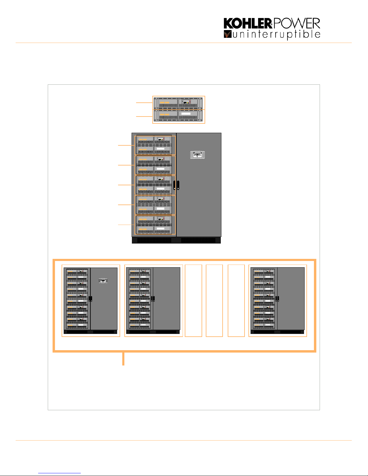
Figure 2.1 PowerWAVE 9500DPA System hardware
Each UPS module comprises two sub-modules; one is known as the ‘Active’ sub-module and the other as the ‘Passive’
sub-module. These are mounted in the UPS cabinet in pairs, with the Active sub-module located on top of the Passive
sub-module. The first module to be installed in the cabinet must be fitted to the bottom position with subsequent modules
fitted in the next lowest available slot. When it is installed in the cabinet, each module is assigned an ID number to allow it
to be identified by the system control logic for purposes such as monitoring and event logging. The modules fitted in the
first cabinet should be identified as illustrated in Figure 2.1. In a multi-cabinet installation, the modules in the second
cabinet are given an identity ‘06’ to ‘10’, those in the third cabinet are given ‘11’ to ‘15’, and so on.
The following table shows the static parameters for each configuration.
1 Module 2 Module 3 Module 4 Module 5 Module
System power rating (per cabinet) (kVA/kW) 100 200 300 400 500
Cabinet weight including modules (kg) 539 648 757 866 975
Cabinet weight without fitted modules (kg) 430
Cabinet dimensions (w x h x d) mm 1580 x 1975 x 940
Heat dissipation 100% linear load (W) 4500 9000 13500 18000 22500
Heat dissipation 100% linear load (BTU) 15395 30717 46076 61434 76793
Heat dissipation 100% non-linear load (W) 5710 11420 17130 22840 28550
Heat dissipation 100% non-linear load (BTU) 19488 38976 58465 77953 97441
Heat dissipation no load (W)) 660 1320 1980 2640 3300
Acoustic noise (@ 100% / 50% load) 75/67dBA (with 5 modules fitted)
Cooling airflow (25°C - 30°C) at full load (m³/s) 1200 2400 3600 4800 6000
Installation clearances (mm) Front 1500, Side 100, Rear 200, Top 400
UPS Module weight Active sub-module = 55 kg, Passive sub-module = 54 kg
UPS Module dimensions (w x h x d) mm Active & Passive modules 710 x 178 x 750
RESET ON/OFF
ON/OFF
ENTER
RESET ON/OFF
ON/OFF
ENTER
RESET ON/OFF
ON/OFF
ENTER
RESET ON/OFF
ON/OFF
ENTER
RESET ON/OFF
ON/OFF
ENTER
rectifier inverter
load
dd.mm.yy
Load protected P:01
hh:mm:ss
RESET ON/OFF
ON/OFF
ENTER
Active sub-module
Passive sub-module
UPS Module 05
UPS Module 04
UPS Module 03
UPS Module 02
UPS Module 01
UPS Module
UPS Cabinet
TS_622_02 PowerWAVE 9500DPA User Manual 26/2/19 5
:
2.3 UPS Module functional description
2.3.1 UPS Module internal operation
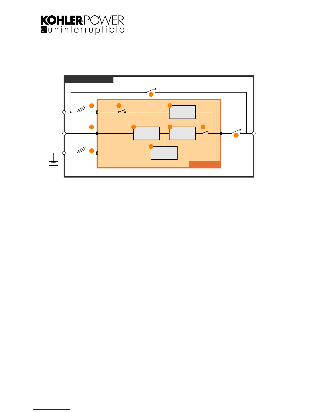
Figure 2.2 UPS module functional block diagram
Figure 2.2 shows an internal functional block diagram of a UPS module installed in a PowerWAVE 9500DPA cabinet.
UPS Module power inputs/outputs (1, 2, 3, 4)
When a UPS module is inserted into the cabinet rack it plugs into a heavy duty power socket located at the rear of the
cabinet which carries the UPS module’s input and output power connections, as shown.
• The UPS input mains (2) is not switched within the cabinet and is connected directly to the UPS module.
• The UPS bypass mains (1) is connected via by fuse F2. Each UPS module is individually fused, with the fuses
labelled F2-x, where ‘x’ denotes the module position within the cabinet. For example the bypass input fuse for the
module fitted to the lowest rack is F2-1, with F2-5 being used to identify the fuse for the top-most module.
• The UPS batteries are installed in an external enclosure and can be configured as a single battery string that is
shared by all the UPS modules (‘common battery’ configuration), or connected as individual battery strings for each
individual module (‘separate battery’ configuration). Irrespective of the external battery configuration, the battery
connection to each UPS module (3) is individually fused by the fuses annotated F3-x, where ‘x’ denotes the module
position within the cabinet, as described above.
• The UPS module a.c. output (4) is connected the cabinet output power terminal via an ‘output isolator’ switch (IA2).
Once again, an individual isolator is provided for each UPS module, annotated IA1-1.... IA1-5. In a redundant-
module parallel UPS system IA2 can be used to disconnect the UPS module from the parallel system output to
allow the module to be replaced, or tested, without affecting the remainder of the system.
Note: In the majority of installations the UPS bypass mains and UPS input mains supplies are linked at the cabinets input
power terminals in what is known as a ‘common input’ configuration. This then requires only one UPS mains supply feed.
Maintenance bypass switch (Optional) (5)
When fitted, the maintenance bypass switch (IA1) (5) provides a means of bypassing ALL the UPS modules fitted in the
PW9500DPA cabinet and connects the cabinet’s output power terminals directly to the UPS bypass mains supply. This
switch can be used to provide the load with unprotected power temporarily if it is necessary to fully power down the UPS
modules. Note that if a maintenance bypass option is required for a multi-cabinet UPS system, the maintenance bypass
switchgear is installed in a separate, external panel and the UPS cabinet internal maintenance bypass switches (IA1) are
not fitted – a typical external maintenance bypass installation is shown on Page 39.
BATTERY
UPS
Input
Mains
UPS
Bypass
Mains
F2
IA1
IA2
F3
UPS AC
Output
Maintenance bypass line
UPS MODULE
PW9500DPA CABINET
RECTIFIER INVERTER
STATIC
SWITCH
BOOSTER /
CHARGER
Bypass
Contactor
Inv. Output
Contactor
Stat ic bypass line
1
2
3
4
5
6
7
8
9
10
11

:
6 TS_622_02 PowerWAVE 9500DPA User Manual 26/2/19
Rectifier (6)
The rectifier (6) converts the UPS input mains to a DC power source that can satisfy the inverter DC power demands over
an input voltage range of between 160V~288V. This wide input voltage range means that the battery is not called upon
even during substantial power dips (brown outs), which maximises battery life and availability. The rectifier control system
uses leading-edge switched-mode techniques which achieves a UPS input power factor of almost unity over its operating
range (0.99 at full rated linear load).
Battery booster/charger (7)
This block has bi-directional functions. When the UPS mains input supply is available, and the rectifier is turned on, the
booster/charger acts as a multi-stage battery charger which uses an intelligent charging profile to optimise the battery life
and ensure the battery recharges quickly following a deep discharge cycle.
If the input mains supply fails, or the rectifier is unable to provide a sufficient output to satisfy the prevailing inverter load,
the battery provides the inverter’s DC operating power source via the booster. The booster contains a DC-DC boost
converter which boosts the battery voltage and provides a regulated DC input to the inverter as the battery discharges to
allow the inverter to operate correctly.
Inverter (8)
The inverter converts the DC voltage produced by the rectifier (or the battery via the boost converter) into a sinusoidal AC
output voltage suitable to connect to the load. In addition to providing output voltage regulation, the inverter control logic
also provides various levels of overload protection, frequency regulation and synchronisation, and output voltage error
detection.
Static switch (9)
The static switch provides a means of connecting the UPS module output to the static bypass line – which is in turn
connected to the UPS bypass mains supply. Working in conjunction with the output contactor, the static switch control
logic is used to transfer the UPS output from the inverter to the static bypass line without a break in the load supply in the
event of an overload or UPS (inverter) malfunction.
Note: A no-break transfer will take place if the inverter frequency and the bypass supply frequency is synchronised.
Inverter output contactor (10)
The inverter output contactor is driven by the UPS module’s control logic and operates in conjunction with the static switch
as part of the bypass/inverter load transfer process. The contactor is also used to isolate the inverter from the UPS output
following certain overload or fault conditions.
Bypass contactor (11)
The bypass contactor is used to isolate the bypass mains from static bypass line if the bypass supply is outside a
specified, or if there is a sustained overload or bypass fault while the UPS is operating on bypass.
2.3.2 UPS Module operational states
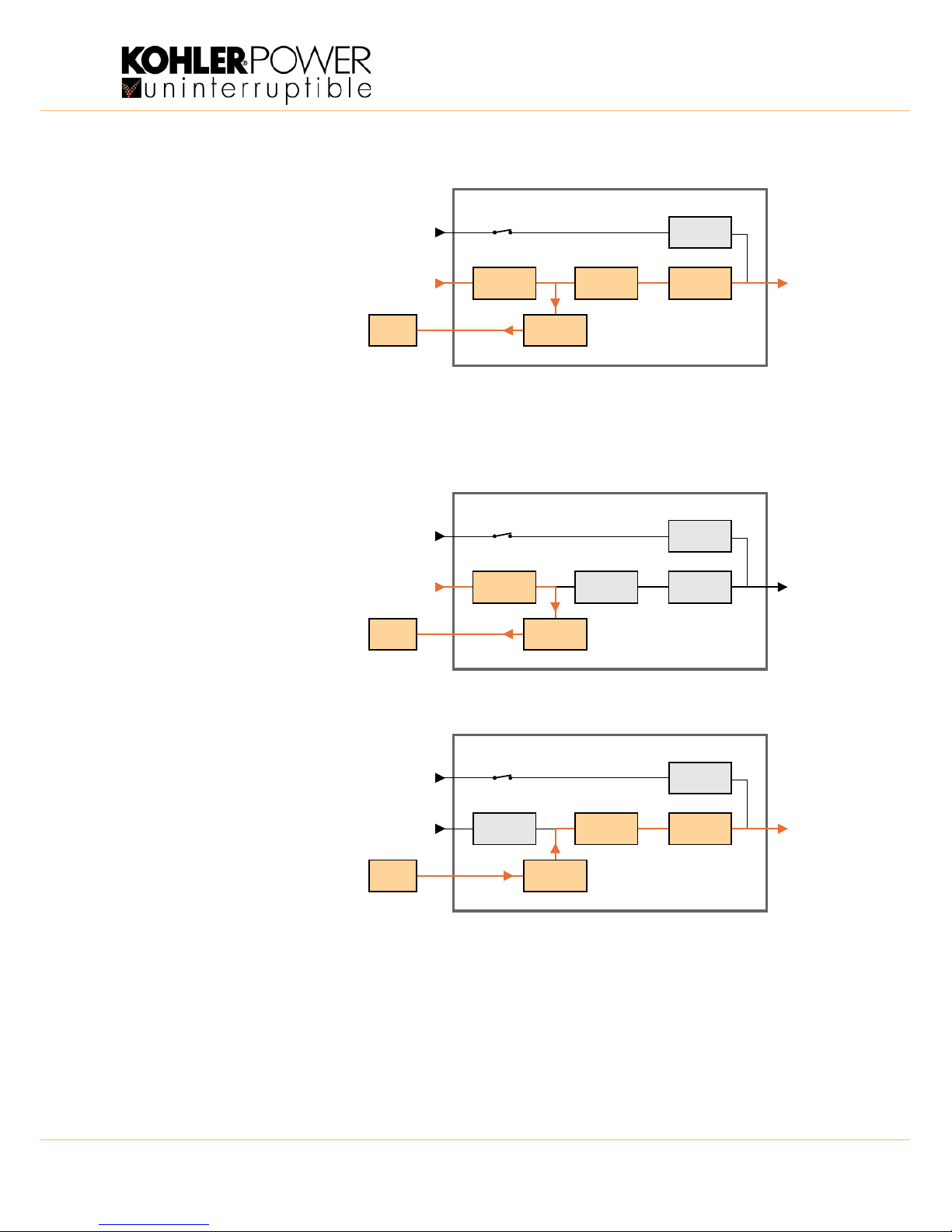
The following simplified block diagrams are used to illustrate the standard operating modes of the UPS module.
Inverter off (load on bypass)
Figure 2.3 shows the internal
operation of the UPS module when
mains power is first applied to the
UPS or the inverter is turned OFF from
the module control panel.
If the mains input supply is available,
the battery charger continues to
charge the battery and the static
switch turns on to connect the UPS
output to the bypass supply.
Figure 2.3 Inverter off
RECTIFIER
BATTERY
INVERTER
STATIC
SWITCH
BOOSTER /
CHARGER
INV. Output
Contactor
UPS MODULE
Static bypass line
Bypass
Contactor
UPS Bypass
Mains
UPS Input
Mains
UPS AC
Output
TS_622_02 PowerWAVE 9500DPA User Manual 26/2/19 7
:
UPS On-inverter mode
This is the only operating mode that
provides the load with continuously
processed and backed-up power: and in
the majority of installations can be
considered as the ‘normal’ operating
mode.
In this mode, the UPS input mains is
converted to DC by the rectifier which
then charges the battery and provides
the operating power for the inverter.
The inverter converts the DC produced
by the rectifier back to an AC power
source which is then connected to the
load via the inverter output contactor.
The inverter frequency is synchronised to the bypass supply provided the bypass frequency remains within preset limits. If
these limits are exceeded, or if the bypass supply fails altogether, the inverter frequency control reverts to a free-running
oscillator which produces a constant 50Hz or 60Hz UPS output.
UPS On-standby (Xtra VFI mode)
Figure 2.5 shows the internal operation
of the UPS module when the Xtra VFI
function is enabled and the UPS is
operating on standby.
The rectifier is turned on and the battery
charger remains active but the inverter
is on standby, and ready when called
upon by the Xtra VFI operation.
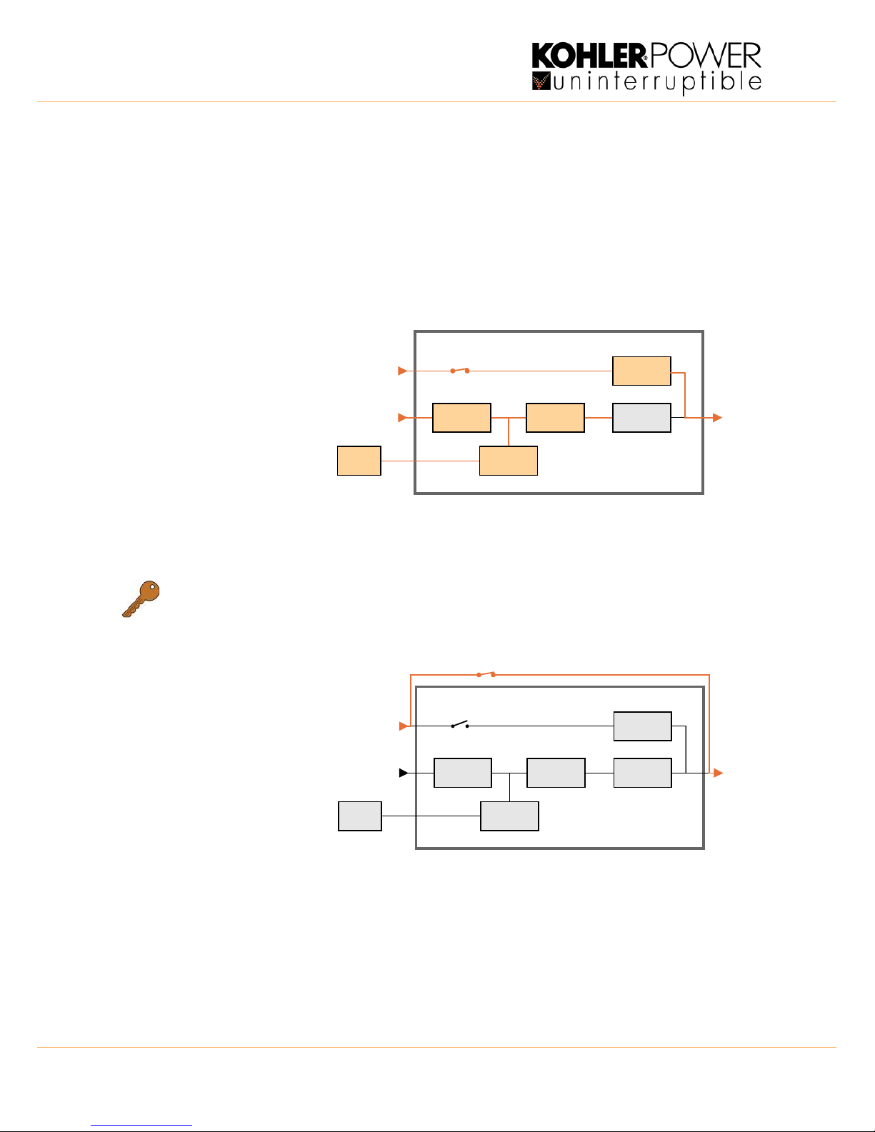
UPS On-battery mode
If the input mains supply fails, the
rectifier shuts down and the battery
provides the DC power source for the
inverter. The battery voltage is
regulated by the booster circuit to
ensure the inverter receives a suitable
DC input voltage as the battery
discharges. On the module control
panel the BATTERY led will flash green
to indicate that it is on load.
In the case of a dual feed input – if the
bypass supply is still live when the input
mains supply fails, the inverter
frequency remains synchronised to the
bypass mains provided it is within its preset limits.
In the case of a single feed input – the bypass supply will fail at the same time as the input mains supply and the inverter
frequency control reverts to its free-running oscillator and will provide a constant 50Hz or 60Hz UPS output.
RECTIFIE R
BATTERY
INVERTER
STATIC
SWITCH
BOOSTER /
CHARGER
INV. Output
Contactor
UPS MODULE
Static bypass line
UPS Bypass
Mains
UPS Input
Mains
UPS AC
Output
Bypass
Contactor
Figure 2.4 UPS On-inverter
Figure 2.5 UPS On-standby
RECTIFIE R
BATTERY
INVERTER
STATIC
SWITCH
BOOSTER /
CHARGER
INV. Output
Contactor
UPS MODULE
Static bypass line
UPS Bypass
Mains
UPS Input
Mains
UPS AC
Output
Bypass
Contactor
RECTIFIER
BATTERY
INVERTER
STATIC
SWITCH
BOOSTER /
CHARGER
INV. Output
Contactor
UPS MODULE
Static bypass line
Bypass
Contactor
UPS Bypass
Mains
UPS Input
Mains
UPS AC
Output
Figure 2.6 UPS On-battery
:
8 TS_622_02 PowerWAVE 9500DPA User Manual 26/2/19
Battery discharge operation
A Low Battery alarm is generated when the battery discharges to a preset level. This allows the operator to gauge the
remaining autonomy time and, if necessary, shut-down the load in an orderly manner (e.g. save data) before the battery
reaches its end-of-discharge voltage. Various options are available to automate the load shut-down process.
When the battery is initially put on load the BATTERY led flashes green on the UPS module control panel and this
continues until the remaining autonomy time falls to 3 minutes whereupon the led begins flashing red. If an automated
data protection application is installed it usually begins its shut down routine at this point.
The BATTERY led changes to solid red when the battery reaches its fully discharged voltage, and the UPS will attempt to
transfer the load to the bypass supply if it is present.
UPS On-bypass mode
In the ‘on bypass’ mode the static
switch connects the load to the
unprotected static bypass line.
This mode can be selected manually
(see ‘ECO Mode’ below) or entered as
the result of a UPS fault or overload
condition which transfers the load to
bypass because the inverter is unable
to support it.
Depending on the reason for entering
the ‘load on bypass’ mode, the rectifier
and charger sections might be turned
off entirely or remain operational and
continue to charge the battery, as shown above. Similarly, the inverter may have been manually turned OFF or shut down
due to a fault, and the INVERTER led on the module control panel may be either OFF or solid RED.
Module OFF (Maintenance bypass)
Note: The maintenance bypass facility
is an optional feature.
When all the UPS modules are turned
OFF, the cabinet’s maintenance
bypass switch (IA-1) can be closed to
maintain the load supply, but this
requires the bypass mains supply to
remain live and thereby prevents the
cabinet’s bypass supply from being
externally isolated.
When operating a multi-cabinet
system, the internal cabinet
maintenance bypass switch is not
normally fitted and an external
maintenance bypass facility that
wraps-around the complete multicabinet system is provided as part of the UPS system installation – see Page 39.
Note: When switching to/from the maintenance bypass mode the UPS is normally transferred to the static bypass mode
before the maintenance bypass switch is operated. This secures the load supply during the switching process.
Key Point: When several UPS modules are connected as a parallel system they must all operate with the same
output mode – i.e. they must ALL be either ‘on-inverter’ or ‘on-bypass’. So if you transfer the load between the
inverter and bypass on one UPS module, every module in the system will automatically change state.
RECTIFIER
BATTERY
INVERTER
STATIC
SWITCH
BOOSTER /
CHARGER
INV. Output
Contactor
UPS MODULE
Static bypass line
Bypass
Contactor
UPS Bypass
Mains
UPS Input
Mains
UPS AC
Output
Figure 2.7 UPS On-bypass
Figure 2.8 Module OFF (Load on maintenance bypass)
RECTIFIER
BATTERY
INVERTER
BOOSTER /
CHARGER
INV. Output
Contactor
UPS MODULE
Static bypass line
IA-1
Maintenance bypass line
STATIC
SWITCH
Bypass
Contactor
UPS Bypass
Mains
UPS Input
Mains
UPS AC
Output

TS_622_02 PowerWAVE 9500DPA User Manual 26/2/19 9
:
2.3.3 UPS system operating modes summary
Section 2.3.2 described the operating modes for the individual UPS modules within the PW9500DPA cabinet: but entire
UPS systems are also categorised according to the way in which they operate at a ‘system’ level, and are typically
described as being either an ‘on-line’, or ‘off-line’ (‘line interactive’) system.
The PowerWAVE 9500DPA can be operated in either of these categories.
On-line UPS system
An ‘on-line’ UPS system provides the highest degree of load protection, especially if the utility mains supply suffers a
disturbance or complete failure, and we always recommended this mode of operation if the critical load will not tolerate
even a very brief supply interruption – e.g. in the case of a computer system.
When the PowerWAVE 9500DPA is used as an ‘on-line’ system, the UPS modules normally operate in their ‘on inverter’
mode (Figure 2.4), and switch to the ‘on battery’ mode if the input mains supply fails (Figure 2.6). The changeover to
battery operation is totally transparent at the UPS output and an audible and visual alarm warns the operator that the
battery is discharging to enable any intervention to be taken to protect the load integrity.
The UPS then continues to provide its rated output until the battery discharges to a low cut-off point at which time the UPS
attempts to switch to its ‘on bypass’ mode (Figure 2.7). If the bypass is unavailable when the UPS attempts to transfer to
it, the UPS shuts down in a controlled manner.
It is usual, especially in larger installations, to provide an alternative UPS input supply from a standby generator which
starts automatically following a utility mains failure; and where this secondary power supply is implemented the batteries
only discharge for a short period, until the generator comes on-line. This not only avoids the UPS shutting down due to a
fully discharged battery but also helps maximise the battery life cycle.
If the UPS experiences an internal fault during ‘on-line’ operation, the inverter turns off and the static switch transfers the
load to bypass mains automatically and without interruption – provided the inverter is synchronised to the bypass. If the
problem is due to an output overload the inverter can supply the overload for a limited time, depending on its severity, and
if the rated time is exceeded the UPS transfer the load to bypass. The additional power available from the bypass supply
will attempt to clear the overload but if it persists it will ultimately rupture the bypass mains supply fuses. However, if the
overload condition clears while operating on bypass the UPS re-transfers the load to the inverter and the UPS returns to
its normal ‘on-line’ mode of operation.
Off-line (On stand-by) UPS system operation
When the PowerWAVE 9500DPA is used as an ‘off-line’ system, the UPS modules are normally operated in their ‘on
bypass’ mode (Figure 2.7) with the load supplied via the static bypass line. However the rectifier and battery charger are
still powered up and maintain battery charging, and the inverter section is turned on and operating on standby.
Operating in this mode is slightly more energy efficient than when operating in the ‘on-line’ mode due to the reduced
rectifier and inverter losses during normal system operation; and it is sometimes referred to as the “ECO” (economy)
mode. However, this mode is recommended only if the connected load equipment can tolerate power interruptions of up to
3~5 ms during the load transfer period.
If the bypass supply fails, the inverter is immediately brought on line and the load is transferred from the static bypass line
to the inverter within 3~5 milliseconds. If the UPS bypass mains and input mains are connected to separate sources (dual
feed) and the input mains is still live when the load is transferred, the UPS modules will operate in their ‘on inverter’ mode
(Figure 2.4). However, if the input/bypass mains supplies are connected to a common feed, or the input mains is
unavailable in a dual feed system, the modules immediately revert to the ‘on battery’ mode (Figure 2.6).
When the bypass supply returns to normal, the load re-transfers to the static bypass line (without a break) and the inverter
returns to its standby operation.
Note: if the bypass is unavailable it is unable to take over the load supply if the inverter fails, or assist the inverter handle
an output overload. It is therefore important that the cause of the load transfer from bypass to inverter is quickly rectified.
WARNING: The ON-LINE mode should always be used for critical load protection.
:
10 TS_622_02 PowerWAVE 9500DPA User Manual 26/2/19
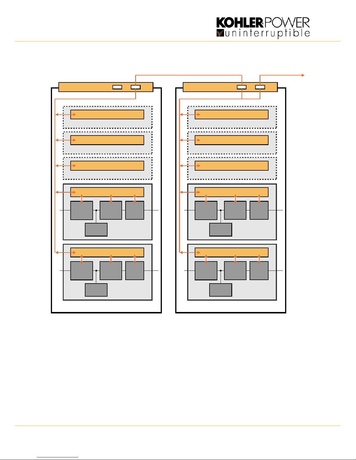
2.4 Parallel system operation
Figure 2.9 PowerWAVE 9500DPA – Parallel cabinet system
All the UPS modules fitted in a PW9500DPA cabinet inherently operate as a parallel system as their outputs are
connected in parallel at the cabinet’s output terminals. The electronic control system built into each module ensures that:
• The modules are always frequency-synchronised to each other – and to the bypass mains (when present).
• The modules equally share the load current.
• The modules’ load transfer operation is synchronised such they ALL transfer their output between inverter and
bypass simultaneously when commanded from any one module.
The PowerWAVE 9500DPA UPS system can be expanded by connecting the outputs of up to six PW9500DPA UPS
cabinets in parallel; and when two or more cabinets are connected in this way, all the UPS modules within them are
effectively paralleled together. A maximum system capacity is obtained by connecting together six fully populated
PW9500DPA cabinets, which results in a total of thirty (100kVA) modules operating in parallel with a system capacity of
3000kVA.
STATIC
SWITCH
INVERTERRECTIF IER
Parallel Control Logic
UPS Module P06
CHARGER
STATIC
SWITCH
INVERTERRECTIF IER
Parallel Control Logic
UPS Module P07
CHARGER
Parallel Control Logic
UPS Module P08
Parallel Control Logic
UPS Module P09
Parallel Control Logic
UPS Module P10
UPS CABINET 2
STATIC
SWITCH
INVERTERRECTIFIER
Parallel Control Logic
UPS Module P01
CHARGER
STATIC
SWITCH
INVERTERRECTIFIER
Parallel Control Logic
UPS Module P02
CHARGER
Parallel Control Logic
UPS Module P03
Parallel Control Logic
UPS Module P04
Parallel Control Logic
UPS Module P05
UPS CABINET 1
Parallel Adapter Board
To JD5 in UPS CABINET 3
JD5 JD6Parallel Adapter Board JD5 JD6

TS_622_02 PowerWAVE 9500DPA User Manual 26/2/19 11
:
System expansion
Some UPS applications present a low initial power requirement which increases over time as the application grows; so it is
essential that the installed UPS system can be expanded to meet the growing demand without compromising the existing
load. This requirement is well met with the ‘hot swappable’ feature of the PowerWAVE 9500DPA UPS, whereby an
additional module can be inserted into a vacant slot in an existing cabinet without disturbing the load.
Note: If the expansion requires an additional cabinet the system will have to be shut down while the cabinet is installed.
‘Capacity’ versus ‘redundant’ module system
A parallel UPS system can be operated as either a ‘capacity’ or ‘redundant’ module system.
A ‘capacity’ system is rated such that ALL the UPS modules are required to furnish the specified full load power and the
loss of one module will automatically transfer the load to the bypass supply.
In a ‘redundant-module’ system, the system contains at least one UPS module over and above that required to supply the
full load and it is therefore possible to lose one module without needing to transfer the load to the bypass supply or in any
way disrupt the UPS output. A system operating with a redundant module is inherently the most reliable.
A parallel UPS system operating with one redundant module is known as an ‘N+1’ system.
Parallel control bus
All the UPS modules within a cabinet, and between cabinets, are connected to a parallel control bus which carries several
control signals used for frequency synchronisation, load sharing etc, as shown in Figure 2.9. This allows each UPS
module to electronically compare its own frequency and output current with that of its neighbouring module and make any
necessary fine adjustments to its control system to achieve balanced conditions across the system.
The parallel control system observes one UPS module as being the ‘master’ and the others as ‘slaves’. However if the
‘master’ module goes faulty the next module in the chain (a former ‘slave’) will immediately take over the role of ‘master’
and the former ‘master’ module will turn off. The ‘master/slave’ configuration is set during commissioning.
2.5 Xtra VFI mode
2.5.1 Introduction
The parallel control mechanism described above ensures that the operational UPS modules in a PowerWAVE 9500DPA
system equally share the load current. However, when the connected load is small in comparison with the system
capacity, the current required from each module can be sufficiently low that it adversely affects the module’s efficiency.
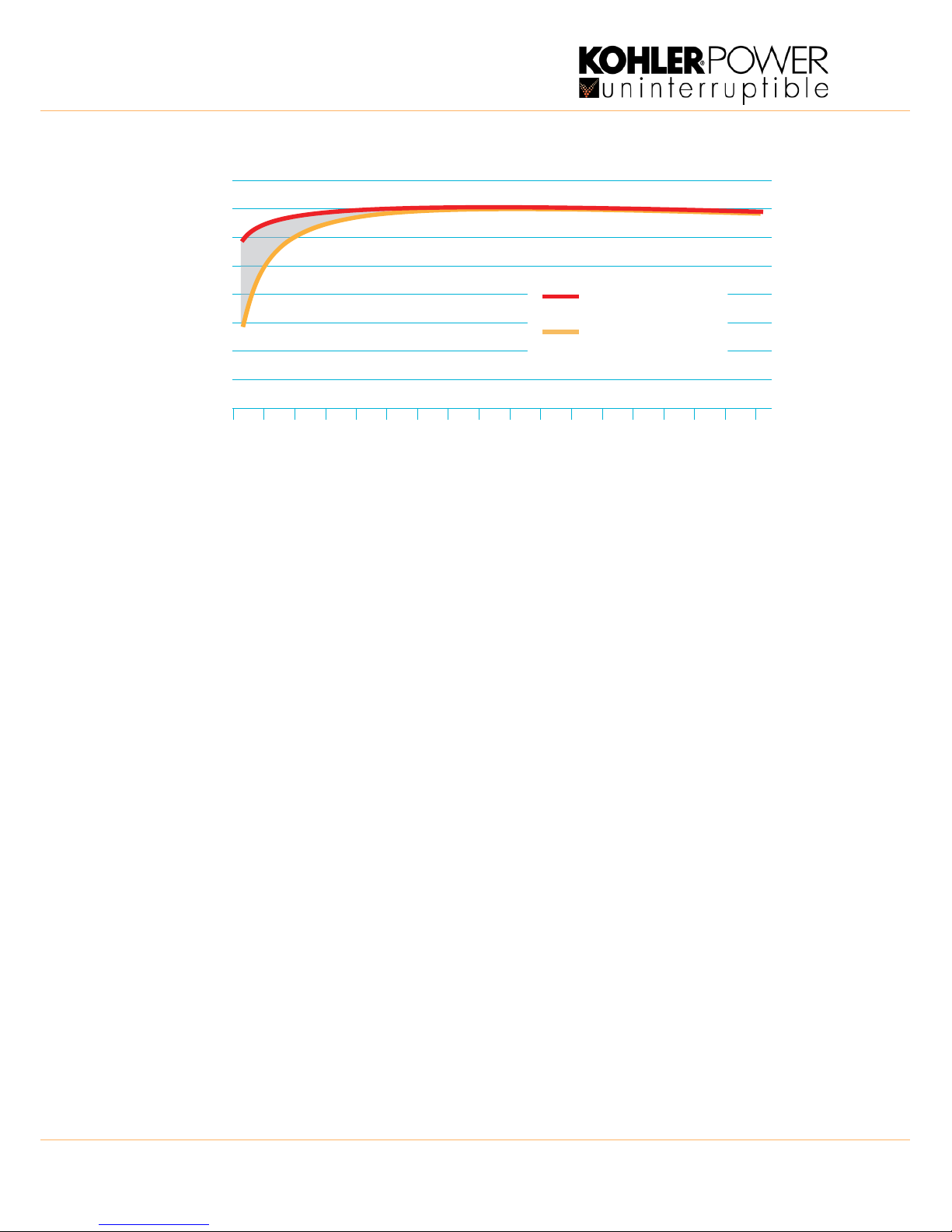
The graph below shows that the efficiency of a standard PowerWAVE 9500DPA UPS module remains at around 96% for
loads of 90% down to approximately 35%, but thereafter the efficiency begins to fall off to approximately 88% @7.5%
load. This reduced efficiency at low load represents wasted energy and expense, and is alleviated by the Xtra VFI feature
which dynamically controls the number of on-line UPS modules in line with changes in load demand.
Xtra VFI calculates the number of UPS modules necessary to supply the prevailing load such that current drawn from
each one places it in the higher range of its efficiency curve and only turns on the required number of modules. Surplus
modules are placed in a ‘standby’ mode, with their inverters turned off, and can be brought back on-line within 40~50ms
when the system load increases. The overall effect of Xtra VFI can improve the system efficiency by up to 5% at very light
loads, as shown in Figure 2.10.
Xtra VFI is an in-built feature, available in every PowerWAVE 9500DPA system, and can be enabled or disabled by a
qualified service engineer with access to the password-protected Service menu on the system control panel.
Key Point: When planning a multi-cabinet system, it is not necessary to fully populate one cabinet with UPS
modules before installing the next cabinet. For example, if it is known at the outset that a 400kVA initial load
requirement is likely to increase to a maximum of 900kVA, it makes sense to install and cable-up two cabinets
and distribute the initial requirement of four UPS modules between them then add further modules as required.
:
12 TS_622_02 PowerWAVE 9500DPA User Manual 26/2/19
Figure 2.10 Efficiency diagram with and without Xtra VFI
2.5.2 Operation
UPS Module standby operation and rotation
When Xtra VFI is operational it switches all non-required UPS modules to ‘standby’ mode whereupon the inverter is turned
off to reduce the module’s power consumption but the rectifier and battery charger remain active – the Inverter LED on the
module control panel indicates yellow when the module is operating on standby.
The Xtra VFI status can be observed on two screens on the system control panel, as shown in figures 3.7 and 3.17.
The active (on-line) UPS modules are rotated on a weekly basis to balance their use over time. This is done automatically
by the Xtra VFI control logic which turns on the in-coming modules before switching the outgoing modules to standby.
An xVFI ROTATING status message is generated at the start of the module rotation process and this is succeeded by
xVFI ACTIVE once the rotation has completed successfully.
Xtra VFI does not require any user intervention during the day-to-day operation of the UPS system. Once the Xtra VFI
feature is enabled it will remain permanently active as long as the following conditions are met:
• There is no active system alarm.
• All the UPS modules within the system are turned on.
• The number of modules in the system is equal to the “Total UPS Number” entered in the Xtra VFI setup screen by
the service engineer.
• The output isolator (IA2) is closed for every UPS module.
• A battery test is not being run.
Xtra VFI setup
The service engineer must enter three parameters in the Xtra VFI setup menu:
• Highest Load Step (HLS) – corresponds to the highest load step to be expected in the system (in <50 ms) that the
UPS system must be able to handle without compromise. This can be entered as a percentage of the system
capacity or in kW.
• Redundancy level – the number of redundant modules required.
• Total UPS number – the total number of UPS modules contained in the system.
The Xtra VFI feature takes these parameters into account when calculating the required number of on-line modules for
any given load.
98%
5
%
1
0
%
1
5
%
2
0
%
2
5
%
3
0
%
3
5
%
4
0
%
4
5
%
5
0
%
5
5
%
6
0
%
6
5
%
7
0
%
7
5
%
8
0
%
8
5
%
9
0
%
96%
94%
92%
90%
88%
86%
84%
82%
Load (% UPS System rated power)
Efficiency (%)
Xtra VFI efficiency
Normal double
conversion efficiency
TS_622_02 PowerWAVE 9500DPA User Manual 26/2/19 13
:
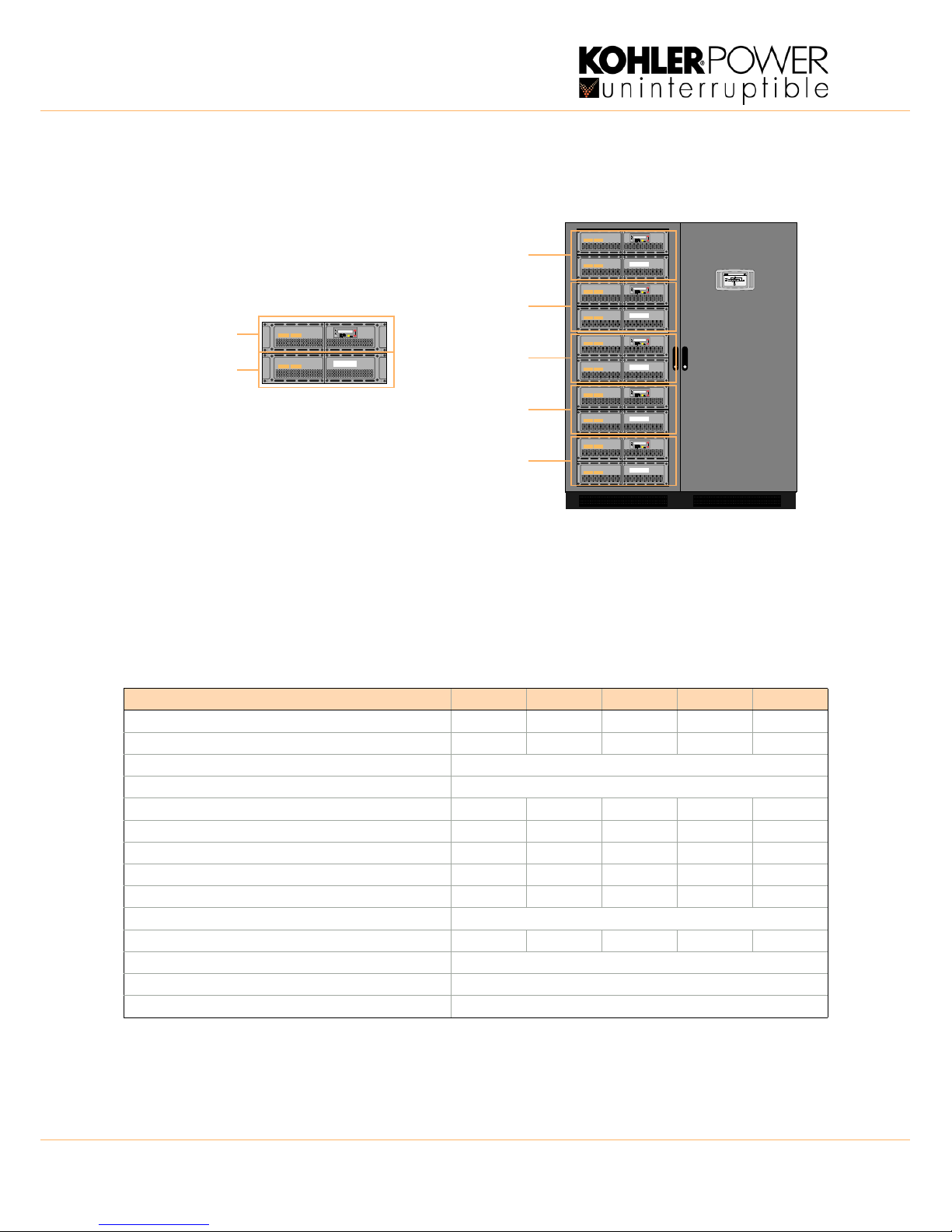
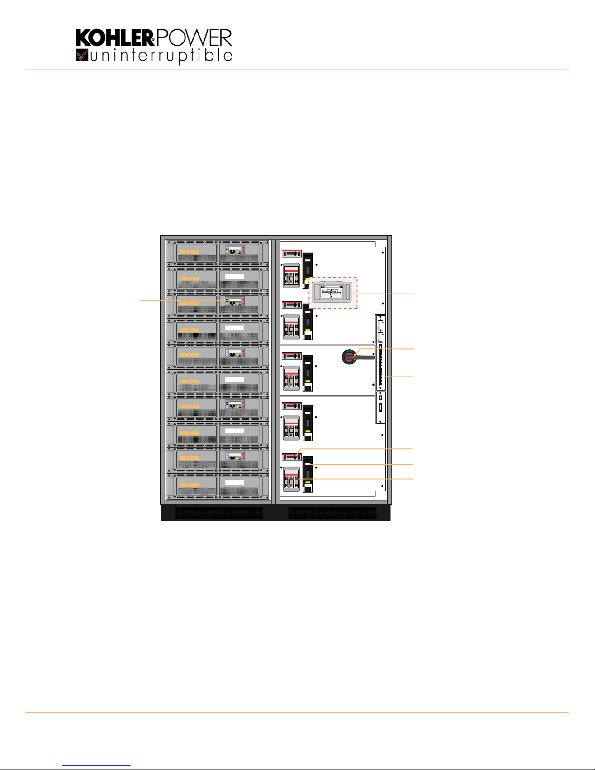
2.6 PowerWAVE 9500DPA Operator controls
This section describes the switches and control panels illustrated in Figure 2.11 that are used to operate and monitor the
PowerWAVE 9500DPA UPS system.
2.6.1 Power switches
Each UPS module has three associated power switches (F2, F3, IA2) located in the right hand cabinet. The electrical
position of these are shown in Figure 2.2. In order to make system expansion straightforward, all the isolators shown are
fitted to the cabinet as standard even if the cabinet is not initially fully populated. This allows additional modules to be
inserted into a vacant cabinet slot without needing to shut down the system to carry out additional mechanical or cabling
work. In a parallel-cabinet system the (optional) maintenance bypass switch is contained in an external bypass facility so
the internal maintenance bypass switch (IA1) is not fitted to the cabinet.
Figure 2.11 Power fuses and isolator switches
RESET ON/OFF
ON/OFF
ENTER
RESET ON/OFF
ON/OFF
ENTER
RESET ON/OFF
ON/OFF
ENTER
RESET ON/OFF
ON/OFF
ENTER
RESET ON/OFF
ON/OFF
ENTER
rectifier inverter
load
dd.mm.yy
Load protectedP:01
hh:mm:ss
IA2 Parallel switch
F3 Fused battery isolator
F2 Fused bypass isolator
Interface board
IA1 (Optional) Maintenance
For Module 5
For Module 4
For Module 3
For Module 2
For Module 1
System Control Panel
Module
Panel
(1 per UPS Module)
(located on front of door)
Bypass Isolator
Only fitted to one cabinet
in a parallel-cabinet system.
Control
(not fitted to parallel cabinets)
:
14 TS_622_02 PowerWAVE 9500DPA User Manual 26/2/19
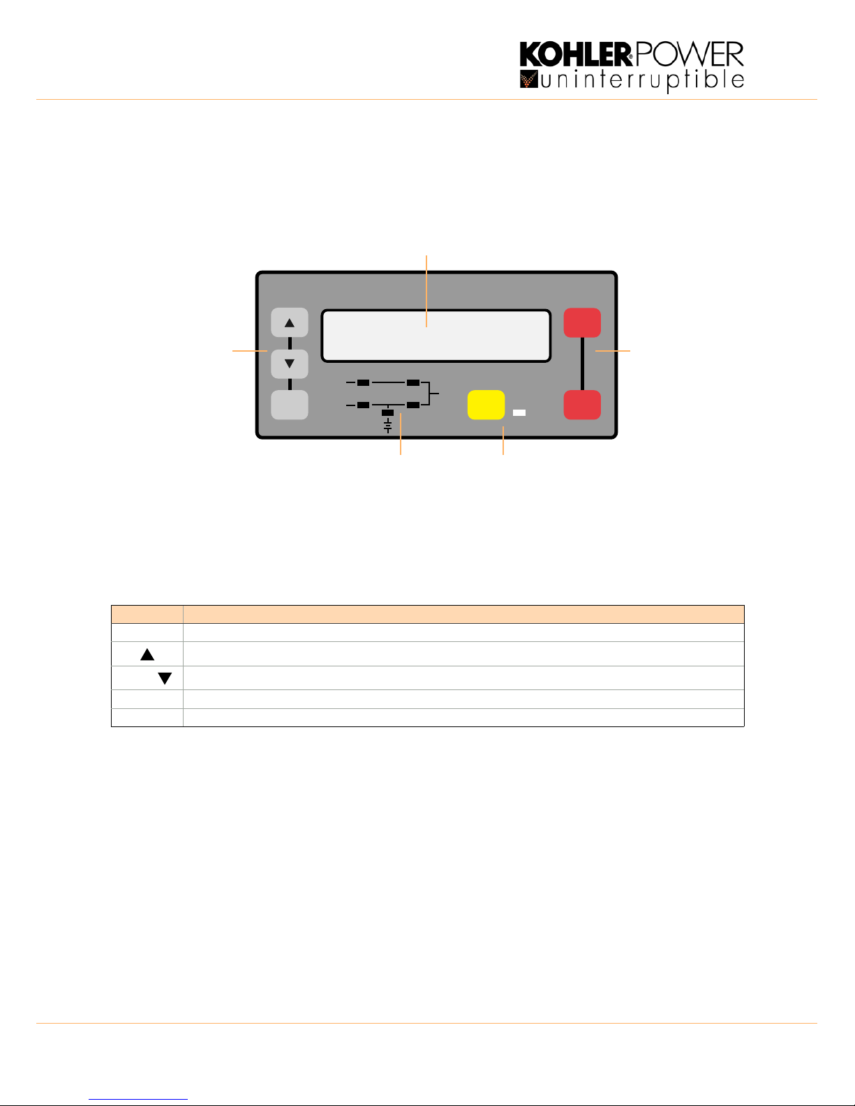
2.7 UPS Module control panel
A control panel is fitted to the front of each UPS module. During normal operation the control panel can be used by the
operator to start/stop the module as part of the UPS system operating procedures, monitor the module’s operating
performance and manually transfer the load between inverter and bypass. The control panel is also used by a trained
service engineer to test and set-up the module’s operating parameters during troubleshooting and commissioning.
Figure 2.12 UPS Module control panel
2.7.1 Module control panel buttons
The module control panel buttons allow you to:
• Start-up and shut-down the UPS and transfer the load between inverter and bypass.
• Monitor and display the UPS operating voltages, currents, frequencies and other values on the LCD display.
• Reset/cancel an alarm.
You can switch the UPS module on or off by simultaneously pressing both ON/OFF buttons (for less than 1s). The
requirement to press both buttons is intended to help prevent accidental operation.
Pressing the two ON/OFF buttons during normal operation will immediately shut down the UPS module. The load may or
may-not transfer to the static bypass, depending on whether or not the number of remaining on-line UPS modules satisfies
the system’s redundancy – i.e. if there is a sufficient number of modules remaining to support the system’s load then the
load is not transferred.
To shut down all the UPS modules in a parallel system you must press both ON/OFF buttons on every module.
BUTTON FUNCTION
ON/OFF Used to switch-on or switch-off the UPS by pressing both buttons simultaneously
UP )
Scroll upwards through a displayed menu
DOWN ()
Scroll downwards through a displayed menu
ENTER Selects a chosen menu item
RESET Cancels an audible alarm. If the alarm condition is transient the alarm LED will turn off, otherwise it will remain on
ENTER RESET ON/OFF
ALARM
LINE 2
LINE 1
BYPASS
INVERTER
BATTERY
ON/OFF
Power Management Display (PMD)
Menu navigation &
selection buttons
Mimic LED indicators Alarm & Reset
Module ON/OFF
control buttons
TS_622_02 PowerWAVE 9500DPA User Manual 26/2/19 15
:
2.7.2 Mimic LED Indication
The mimic diagram LEDs indicate the general power flow through the UPS module and changes colour between Green
and Red (and OFF) to indicate the prevailing UPS module operating conditions.
* The ALARM LED is a visual indication of an internal or external alarm condition. When activated, it is accompanied by an
audible warning which can be cancelled by pressing the RESET button.
2.7.3 Power Management Display (PMD)
A 2 x 20 character LCD Display simplifies communication with the UPS module and provides monitoring information.
The menu driven LCD provides:
• Access to an ‘event’ register
• Input and output voltage, current, frequency & power monitoring
• Battery run time monitoring
• Access to commands such as module load transfer between INVERTER and BYPASS
• Access to the module’s diagnostics registers (service mode only)
• Access to module adjustments and testing (service mode only)
Status screens
INDICATOR INDICATOR STATUS INTERPRETATION
LINE 1 GREEN
RED
OFF
Input (rectifier) mains available
Input (rectifier) mains unavailable
No input (rectifier) supply (UPS Turned off)
LINE 2 GREEN
RED
OFF
Bypass mains available (bypass OK)
Bypass mains unavailable (bypass supply error)
No bypass supply (UPS Turned off)
ALARM* OFF
Flashing RED + buzzer
RED
No alarm condition
Alarm condition
Alarm condition present (audio has been reset)
INVERTER GREEN
RED
YELLOW
OFF
Load on inverter
Inverter fault or load transfer to inverter inhibited
Inverter in standby mode (valid for Xtra VFI operation only)
Inverter not operating (switched off)
BY-PASS GREEN
OFF
Load on bypass (or in ECO mode)
Bypass not operating (turned off)
BATTERY GREEN
RED
Flashing GREEN
Battery OK
Battery faulty or discharged
Battery on load (discharging) or battery fuse open
DESCRIPTION LCD-DISPLAY
1. Load is protected and being supplied by the UPS inverter
(Normal Operation).
LOAD
PROTECTED
01
2. Load is not protected by UPS. It is either connected to the bypass (load on bypass) or
connected to the inverter but with a battery problem.
LOAD
NOT PROTECTED
01
3. Load supply completely powered-down.
UPS modules have all been switched off by “ON/OFF” buttons.
LOAD OFF
SUPPLY FAILURE
01
4. UPS module is not supplying load.
The UPS output switch (IA2) is open.
LOAD DISCONNECTED
PARALLEL SWITCH OPEN
01
:
16 TS_622_02 PowerWAVE 9500DPA User Manual 26/2/19
The two-digit number on the right hand side of the LCD indicates the power module ID number (see Figure 2.9).
Main menu screen
Event log menu screen
Measurements menu screen
DESCRIPTION LCD-DISPLAY
1. Single module systems. SYSTEM CONFIGURATION
SINGLE
S
2. Parallel System – e.g. bottom module in cabinet 2: SYSTEM CONFIGURATION
PARALLEL
P06
3. Parallel System – e.g. top module in cabinet 3: LOAD OFF
SUPPLY FAILURE
P15
DESCRIPTION LCD-DISPLAY
1. Provides access to a log of the last 64 stored events. EVENT LOG
MEASUREMENTS
2. Provides access to voltages, power, frequencies, currents, autonomy monitor screens. MEASUREMENTS
COMMANDS
3. Provides access to the ‘Load to inverter’, ‘Load to bypass’ and ‘battery test’ commands. COMMANDS
UPS DATA
4. Allows personalised UPS data (such as serial number) to be entered. UPS DATA
SET-UP USER
5. Allows the user to set up Date/Time, automatic battery test, etc. SET-UP USER
SET-UP SERVICE
6. This is a password-protected area for service engineer use only. SET-UP SERVICE
DESCRIPTION LCD-DISPLAY
1. Logging Control; a log of the last stored 64 events.
01 05-10-08 14-38-56
LOAD TO INV.
2. Every stored event is identified with a sequential number and time stamp. 02 05-10-08 14-38-59
LOAD TO BYP.
3. By pressing ENTER the code of the event will be displayed.
03 05-10-08 14-39-14
LOAD OFF
DESCRIPTION LCD-DISPLAY
1. Battery Runtime BATT. RUN TIME (MIN)
00h 00mm
2. UPS-Output Frequency OUTPUT FREQUENCY (HZ)
50.00
3. Bypass Frequency. BYPASS FREQUENCY (HZ)
50.00
4. Battery Voltage BATTERY VOLTAGE (V)
+0.0 - 0.0
5. Battery Charger Current BATT. CHARGE CUR. (A)
+ 0.0 - 0.0
6. Battery Discharge Current. DISCHARGE CURRENT (A)
00.00
TS_622_02 PowerWAVE 9500DPA User Manual 26/2/19 17
:
Commands menu screen
UPS Data menu screen
7. Rectifier Voltage (all three phases) RECTIFIER VOLTAGE (V)
00.00 00.00 00.00
8. Bypass Voltage (all three phases) BYPASS VOLTAGE (V)
00.00 00.00 00.00
9. Output Voltage (all three phases) OUTPUT VOLTAGE (V)0
0.00 00.00 00.00
10.Output Current (all three phases) OUTPUT CURRENT (A)0
0.00 00.00 00.00
11.Active Output Power (all three phases) ACTIVE POWER (KW)
00.00 00.00 00.00
12.Reactive Output Power (all three phases) REACTIVE POWER (kVAr)
00.00 00.00 00.00
13.Apparent Output Power (all three phases) APPARENT POWER (KVA)
00.00 00.00 00.00
14.Output Power (all three phases) OUTPUT POWER (%)
00.00 00.00 00.00
15.Battery capacity BATT. CAPACITY (%)
00.00
DESCRIPTION LCD-DISPLAY
1. Transfer Load to inverter LOAD TO INVERTER
LOAD TO BYPASS
2. Transfer Load to bypass. LOAD TO BYPASS
PERFORM BATT.TEST
3. Battery Test PERFORM BATT.TEST
DESCRIPTION LCD-DISPLAY
1. These general UPS Data are installed at the manufacturing plant. UPS SERIAL NUMBER
nn-nnnnn
2. Manufacturing date DATE OF MANUFACTURE
15-03-16
3. EPROM Version EPROM VERSION
V-000
4. Actual Date and Time DATE TIME
dd-mm-yyyy hh:mm:ss
DESCRIPTION LCD-DISPLAY
:
18 TS_622_02 PowerWAVE 9500DPA User Manual 26/2/19
Set-up User menu screen
Set-Up Service menu screen
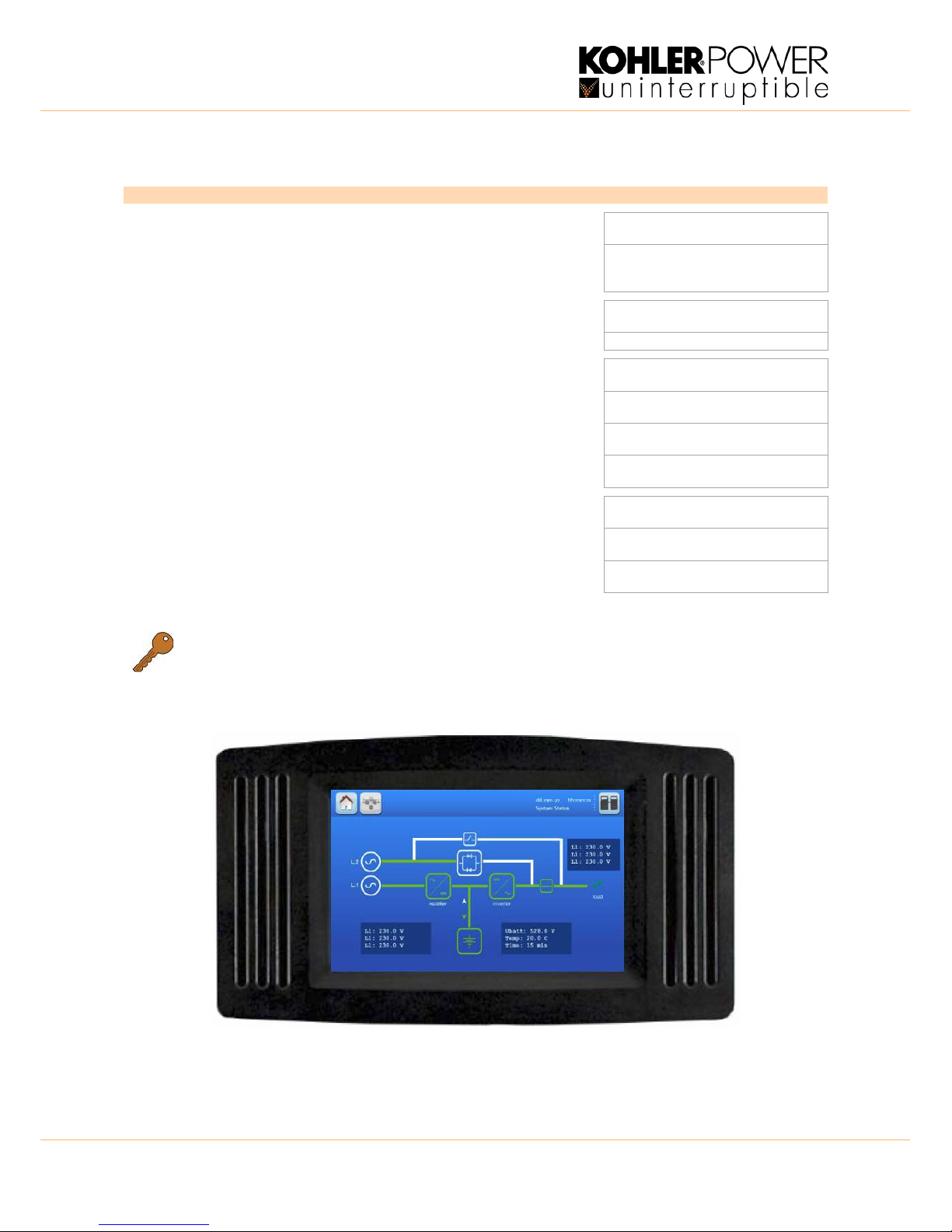
2.8 System control panel
Figure 2.13 System control panel default display
The system control panel contains a TFT touch-screen display which enables you to monitor and operate the UPS
installation at a ‘system’ level. A detailed description of the control panel is provided in Chapter 3.
DESCRIPTION LCD-DISPLAY
1. Set-up language SET LANGUAGE
SET DATE AND TIME
ENGLISH
FRANCAIS
POLISH
2. Set-up Date and Time SET-UP DATE/TIME
SET-UP BATT. TEST
DD-MM-YY HH-MM-SS
3. Set-up battery test SET-UP BATT. TEST
SET-UP GEN-SET OPER.
DAY OF MONTH
(1-31)
HOUR OF DAY
(0-23)
REPETITIVE (Y/N)
000
4. Set-up operation with Gen-Set SET GENERATOR OP.
BATT.CHARGE LOCK
(Y/N)
BYPASS LOCK
(Y/N)
Key Point: This area is password protected and access is restricted to approved Service Engineers only.
 Loading...