

Kohler MAXISPACE Installation Instructions Manual

-1-
MAXISPACE
INSTALLATION INSTRUCTIONS
K-96106T-R/K-96106T-L/K-96107T
MIRRORED CABINET
BEFORE YOU BEGINBEFORE YOU BEGIN
!
!
!
!
!
Please read these instructions carefully to familiarize
yourself with the required tools, materials, and installation
sequences. Follow the sections that pertain to your
particular installation . This will help you avoid costly
mistakes. In addition to proper installation, read all
operating and safety instructions.
All information in these instructions is based upon the
latest product information available at the time of
publication. Kohler China. reserves the right to make
changes in product characteristics, packaging, or
availability at any time without notice.
These instructions contain important care, cleaning, and
warranty information-
Before installation carefully inspect the new fixture for any
signs of damage.
This product complies with GB/T10357.4-2013,
GB/T10357.5-2013 and GB24977-2010.
Be
careful when opening the door to avoid pinching
fingers.
Don't use acidic or alkalic cleaners or
alcohol to clean the surface. Use a dampened cloth to
clean.
Electrical wiring
may need to be relocated.
Use anchors
(not provided) rated for the loaded weight of this
product. Refer to the anchor manufacturer's
instructions.
This cabinet is designed for
either right or left door swing. Check the wall cavity for
obstructions.
please leave instructions for the
consumer.
WARNING: Risk of injury or product damage.
WARNING:
CAUTION: Risk of electric shock.
CAUTION: Risk of property damage.
Important Information:
!
!
!
!
!
-
GB/T10357.4-2013 GB/T10357.5-2013
GB24977-2010
ZHONGSHAN KOHLER SHOWER CO., LTD. NO13-1, XINYE ROAD, ZHONGSHAN TORCH
DEVELOPMENT ZONE, ZHONGSHAN, GUANGDONG, CHINA POST CODE: 528437
13-1 528437
©©Copyright Kohler China Investment Co., Ltd. 2017
2017
1261996-T01-B
-2-
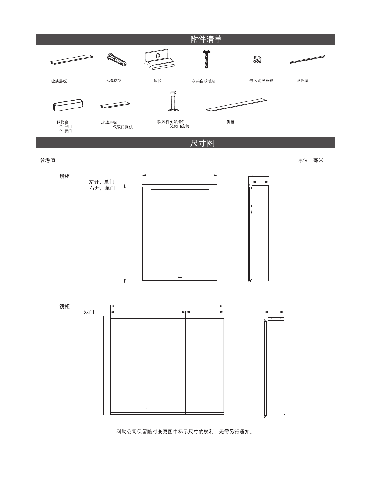
Kohler reserves the right to change marked dimensions without prior notice.
ROUGHING-IN
UNIT : mm
Reference Value
Mirrored Cablnet
K-96106T-L( )
K-96106T-R( )
Mirrored Cablnet
K-96107T( )
Glass Shelves
546*118*6mm
2PCS
Wall Anchors
5PCS
Top Clips
3PCS
Screw ST3.5X35
ST3.5X35
5PCS
Shelf Clip
10PCS
Mounting Bar
1PCS
Storage, Plastic
2( )
3( )
Glass Shelves
256*118*6mm
2PCS( )
Holedr, Dryer, Assy.
1PCS( )
ACCESSORIS LISTACCESSORIS LIST
590
158
130
776
776
890
590 297
158
130
Side Mirror
2PCS
1261996-T01-B
-3-
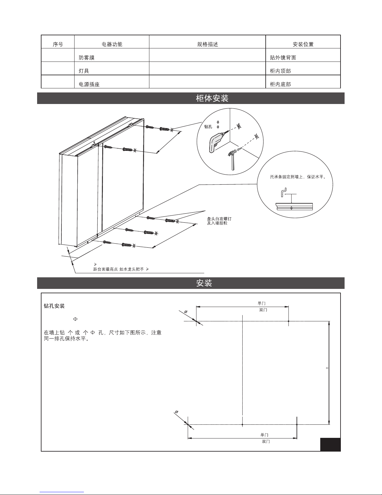
CABINET INSTALLATIONCABINET INSTALLATION
Item
Electrical Function
Type Descripetion
Fixate Place
Defogger
Input: 220V 50Hz, Pmax=30W
Back of outer-mirror
Lighting
Input: 220V 50Hz, Pmax=6W, LED 3000K
Top of inner cabinet
Power Outlet
Input: 220V 50Hz, 10A
Bottom of inner cabinet
1
2
3
INSTALLATION
STEP
2
Drill mounting holes
Drill 5 (or 4) 6 holes on the wall as shown. The
holes on the same line shall keep level.
5(4)6
5- 6
6
745 0.3
L1=320(Single Door )
L2=320(Single Door )
L1=500(Double Door )
L2=590(Double Door )
558.5
L2
L1
40mm from top part of the countertop (such as faucet)
()40
Screw ST3.5x35
and Wall Anchor
ST3.5x35
Drill holes
4- 6mm
4- 6mm
Drill holes
4- 6mm
4- 6mm
Fix the mounting bar to the
wall, level the mounting bar.
1261996-T01-B
 Loading...