

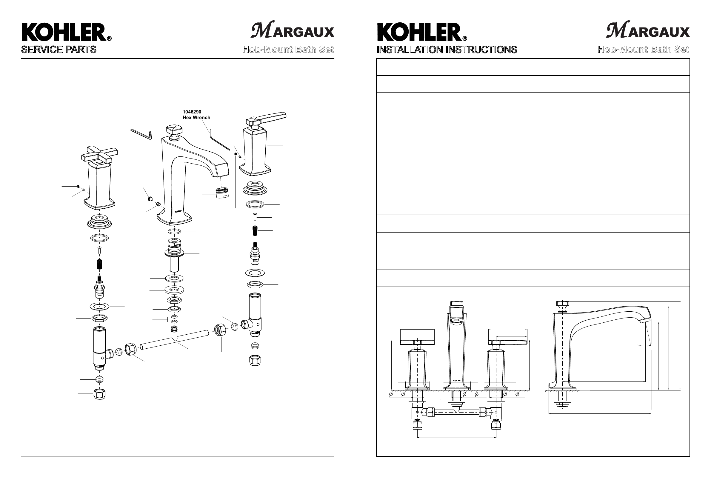
1046290
Hex Wrench
SERVICE PARTS
1087132-C**(Right)
1087132-H**(Left)
Cross Handle Kit
(Only for 16228A-3)
88005**
Plug Button Kit
1041023
Screw
1070772
Nut
871306
Washer
1032218
Spline Adapter
1119280(Left)
Valve
864342
Nut
1156038
Side Body Assy
1119982
Nylon Compression Olive
1126106
Nut
16228A HOB-MOUNT BATH SET
66637
Hex Wrench
88057**
Plug Button Kit
88454**
Aerator
46112
Screw
871472
O-ring
834851
Screw
871575
washer
835726
Metal Washer
830915
Washer
1119982
Nylon Compression Olive
860091
Nut
20960
O-ring
1126106
Nut
1154304
Shank
865099
Nut
1119982
Nylon Compression Olive
1119976
Tee
1041023
Screw
88005**
Plug Button Kit
830915
Washer
1126106
Nut
Hob-Mount Bath Set
1085333-C**(Right)
1085333-H**(Left)
Lever Handle Kit
(Only for 16228A-4)
1070772
Nut
871306
Washer
834851
Screw
1032218
Spline Adapter
Valve(Right)
1119280(Only for 16228A-3)
1119281(Only for 16228A-4)
864342
Nut
1156038
Side Body Assy
1119982
Nylon Compression Olive
1126106
Nut
INSTALLATION INSTRUCTIONS
Hob-Mount Bath Set
16228A HOB-MOUNT BATH SET
BEFORE YOU BEGIN
All information is based on the latest product information available at the time of publication. Kohler Co.
reserves the right to make changes in product characteristics, packaging, or availability at any time without
notice.
Please leave these instructions for the consumer. They contain important information.
NOTES:
1. Flush the water supply pipes thoroughly to remove debris.
2. An in line water filter must be used with this product.
3. Inspect the supply pipes for damage. Replace as necessary.
4. Observe local plumbing codes.
5. If possible, install this bath set before installing the bath tub.
6. Recommended working pressure: 1 to 5 bars.
7. Maximum working pressure: 8 bars.
8. All installations should comply with the relevant requirements of AS/NZS 3500.
HANDLE OPERATION
For 16228A-4, left handle opens with one-quarter turn counter-clockwise; right handle opens with one-quarter
turn clockwise.
For 16228A-3, both handles open with one-quarter turn counter-clockwise.
ROUGH-IN DIMENSIONS
Cross Handle
15581A-3
90
132
63
Max 28
32~ 38
72
25~ 35
Lever Handle
15581A-4
102
86
63
32~ 38
132
217.5
。
13
222
180
233.5
**Color code must be specified when ordering
1154902-AN2-A 4
267
Recommended Distance
203
1154902-AN2-A 1
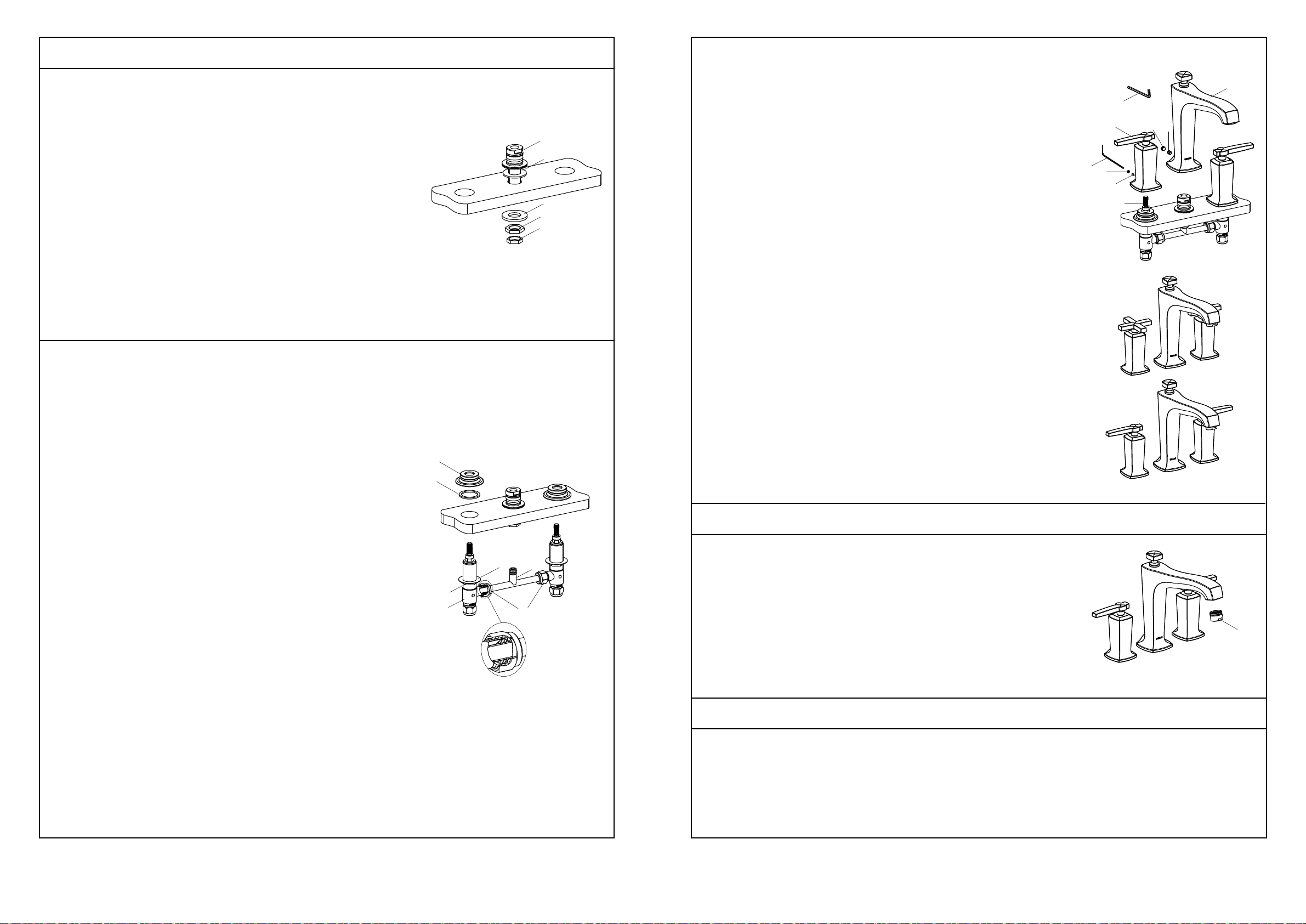
INSTALLATION
How To Install The Handles And The Spout
How To Install The Spout Shank
Remove the parts from the shank(1) and retain them according to the
following order: the nut(2), the nut(3) and the metal washer(4).
Install the foam washer(5) to the shank, then insert the shank into the
center hole of the deck or bath tub.
From the underside of the deck or bath tub, install the metal washer(4),
the nut(3), and the nut(2), use a wrench to tighten the nut(3), then tighten
the nut(2).
How To Install The Side Bodies
Remove the parts from the side bodies(8) according to the following
order: the collars(6) and the rubber washers(7). Trim the tee-piece(9) to
suit the deck or bath tub hole centres. Loosen the nuts(10) on the side
bodies, and assemble the tee-piece to the side bodies. Tighten the
nuts(10) by hand.
Press the handle kits(16) onto the valve stems(13) until they contacts the
deck as Fig.1 shown.
1
5
4
3
2
NOTE: The screws face the back. The handle kit with red washer should
be installed on the left.
Tighten the screws(14) by the hex wrench(20), then insert the plug
buttons(15) into the rear holes.
20
15
16
14
21
13
17
18
Fig.1
19
Insert the spout(19) to the shank until it contacts the deck. Tighten the
screw(18) by the hex wrench(21), then insert the plug button(17) into the
rear hole.
The illustration Fig.2 shows the correct position for the installed spout
and handles when closed.
Insert the side bodies with the washers(11) and the nuts(12) through the
mounting holes from underside of the deck or bath tub (The side body
with the red dot should be on the left when facing the front of the bath
set), and locate the tee-piece onto the spout shank.
If the tee-piece cannot be inserted into the shank, you can loosen the
nuts(10) by hand, and adjust the tee-piece position. Then tighten the
nuts(10) with a wrench.
Install the rubber washers(7) and the collars(6) onto the side bodies.
Tighten the nuts(12) with a wrench.
Attach the water supplies to the valve bodies. Hot water to left valve
body, cold water to right valve body.
6
7
Fig.2
INSTALLATION CHECKOUT
Ensure that all connections are tight. Ensure that the handles are in the
off position.
Turn on the drain and main water supply, and check for leaks. Repair as
needed.
Remove the aerator(22). Turn on the tap handles. Run the water through
22
12
11
8
9
10
the spout about one minute to remove any debris. Remove any debris
from the aerator. Shut off the tap handles. Reinstall the aerator.
CLEANING INSTRUCTIONS
All Finishes: Clean the finish with mild soap and warm water. Wipe entire surface completely dry with clean
soft cloth. Many cleaners may contain chemicals, such as ammonia, chlorine, toilet cleaner etc. which could
adversely affect the finish and are not recommended for cleaning.
1154902-AN2-A 2
Do not use abrasive cleaners or solvents on Kohler faucets and fittings.
1154902-AN2-A 3
 Loading...