

SERVICE MANUAL
AEGIS
LIQUID-COOLED
HORIZONTAL CRANKSHAFT
LH630-775
™

Contents
Section 1. Safety and General Information ............................................................................
1
Section 2. Tools & Aids ..........................................................................................................
Section 3. Troubleshooting .....................................................................................................
Section 4. Air Cleaner System.................................................................................................
Section 5. Fuel System and Governor....................................................................................
Section 5B. Electronic Fuel Injection (EFI) Fuel System ......................................................
Section 6. Lubrication System ................................................................................................
Section 7. Cooling System ......................................................................................................
2
3
4
5
5B
6
7
Section 8. Electrical System and Components .....................................................................
Section 9. Disassembly ...........................................................................................................
Section 10. Inspection and Reconditioning ...........................................................................
Section 11. Reassembly...........................................................................................................
8
9
10
11
Safety and General Information
Section 1
Safety and General Information
Safety Precautions
To ensure safe operations please read the following statements and understand their meaning. Also
refer to your equipment manufacturer's manual for other important safety information. This manual
contains safety precautions which are explained below. Please read carefully.
WARNING
Warning is used to indicate the presence of a hazard that can cause severe personal injury, death,
or substantial property damage if the warning is ignored.
CAUTION
Caution is used to indicate the presence of a hazard that will or can cause minor personal injury or
property damage if the caution is ignored.
Section 1
1
NOTE
Note is used to notify people of installation, operation, or maintenance information that is important
but not hazard-related.
For Y our Safety!
These precautions should be followed at all times. Failure to follow these precautions could result in injury to
yourself and others.
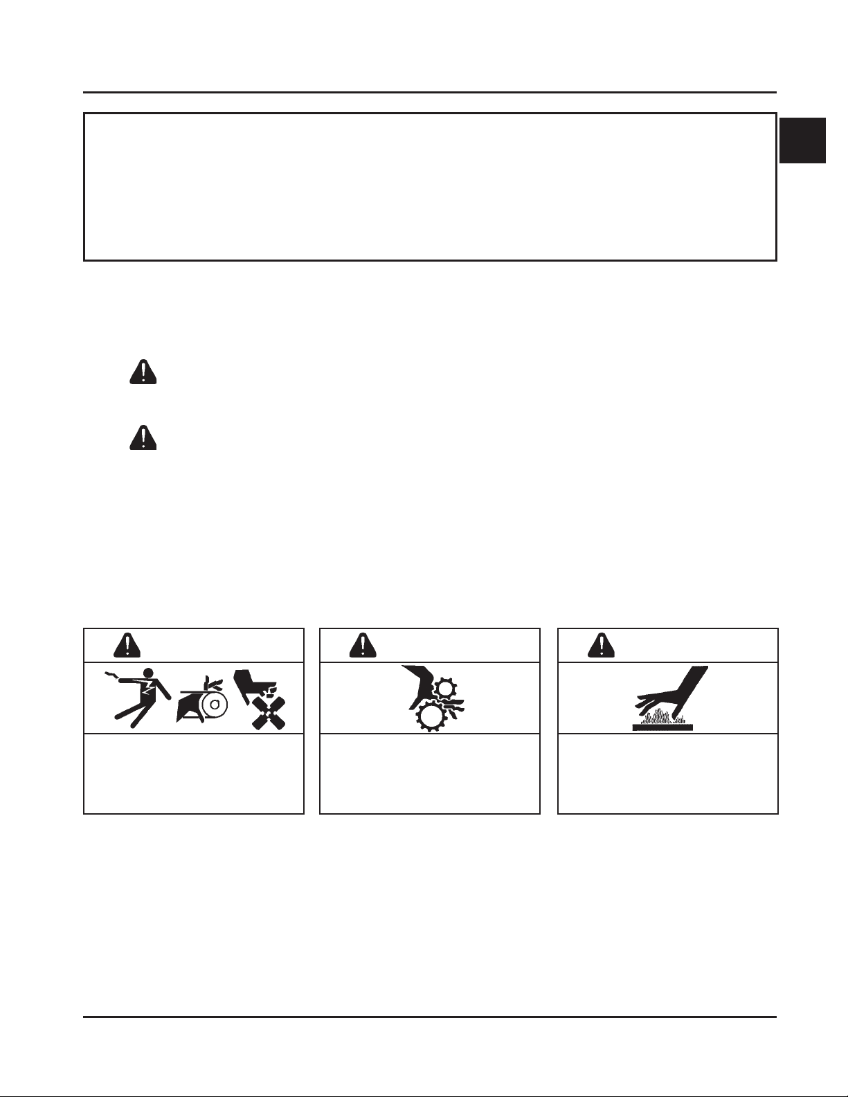
WARNING
Accidental Starts can cause
severe injury or death.
Disconnect and ground spark plug
leads before servicing.
Accidental St arts!
Disabling engine. Accidental
starting can cause severe injury or
death. Before working on the engine or
equipment, disable the engine as
follows: 1) Disconnect the spark plug
lead(s). 2) Disconnect negative (-)
battery cable from battery.
WARNING
Rotating Parts can cause severe
injury.
Stay away while engine is in
operation.
Rotating Part s!
Keep hands, feet, hair, and clothing
away from all moving parts to prevent
injury. Never operate the engine with
covers, shrouds, or guards removed.
Hot Parts can cause severe burns.
Do not touch engine while operating
or just after stopping.
Hot Parts!
Engine components can get extremely
hot from operation. To prevent severe
burns, do not touch these areas while
the engine is running - or immediately
after it is turned off. Never operate the
engine with heat shields or guards
removed.
WARNING
1.1
Section 1
Safety and General Information
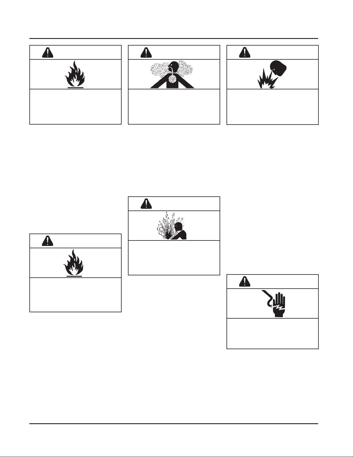
WARNING
Explosive Fuel can cause fires
and severe burns.
Do not fill the fuel tank while the
engine is hot or running.
Explosive Fuel!
Gasoline is extremely flammable and
its vapors can explode if ignited. Store
gasoline only in approved containers,
in well ventilated, unoccupied
buildings, away from sparks or flames.
Do not fill the fuel tank while the
engine is hot or running, since spilled
fuel could ignite if it comes in contact
with hot parts or sparks from ignition.
Do not start the engine near spilled
fuel. Never use gasoline as a cleaning
agent.
WARNING
WARNING WARNING
Carbon Monoxide can cause
severe nausea, fainting or death.
Avoid inhaling exhaust fumes, and
never run the engine in a closed
building or confined area.
Lethal Exhaust Gases!
Engine exhaust gases contain
poisonous carbon monoxide. Carbon
monoxide is odorless, colorless, and can
cause death if inhaled. Avoid inhaling
exhaust fumes, and never run the
engine in a closed building or confined
area.
WARNING
Hot liquid can cause severe
burns.
Do not loosen radiator cap while
engine is operating or warm to the
touch.
Explosive Gas can cause fires
and severe acid burns.
Charge battery only in a well
ventilated area. Keep sources of
ignition away.
Explosive Gas!
Batteries produce explosive hydrogen
gas while being charged. To prevent a
fire or explosion, charge batteries only
in well ventilated areas. Keep sparks,
open flames, and other sources of
ignition away from the battery at all
times. Keep batteries out of the reach of
children. Remove all jewelry when
servicing batteries.
Before disconnecting the negative (-)
ground cable, make sure all switches
are OFF. If ON, a spark will occur at
the ground cable terminal which could
cause an explosion if hydrogen gas or
gasoline vapors are present.
Cleaning Solvents can cause
severe injury or death.
Use only in well ventilated areas
away from ignition sources.
Flammable Solvents!
Carburetor cleaners and solvents are
extremely flammable. Keep sparks,
flames, and other sources of ignition
away from the area. Follow the cleaner
manufacturer’s warnings and
instructions on its proper and safe use.
Never use gasoline as a cleaning agent.
1.2
Hot Liquid!
The liquid coolant can get extremely
hot from operation. Turning the
radiator cap when the engine is hot can
allow steam and scalding liquid to blow
out and burn you severely.
Shut off machine. Only remove
radiator cap when cool enough to touch
with bare hands. Slowly loosen cap to
first stop to relieve pressure before
removing completely.
CAUTION
Electrical Shock can cause injury.
Do not touch wires while engine is
running.
Electrical Shock!
Never touch electrical wires or
components while the engine is
running. They can be sources of
electrical shock.

Engine Identification Numbers
When ordering parts, or in any communication
involving an engine, always give the Model,
Specification, and Serial Numbers, including letter
suffixes if there are any.
The engine identification numbers appear on a decal,
or decals, affixed to the engine. The primary location
is on the side of the flywheel cover. See Figure 1-1.
Placement may vary due to OEM requirements and
specific options involved. An explanation of these
numbers is shown in Figure 1-2.
Section 1
Safety and General Information
1
Identification Decal
Figure 1-1. Engine Identification Decal Location.
A. Model No.
Liquid Cooled
Horizontal Crankshaft
Numerical Designation
B. Spec. No.
Model
LH630-0001
LH640-0001
LH685-0001
LH690-0001
LH750-0001
LH755-0001
LH760-0001
LH775-0001
C. Serial No.
Year Manufactured Code
Code Year
31 2001
32 2002
33 2003
34 2004
35 2005
36 2006
37 2007
Figure 1-2. Explanation of Engine Identification Numbers.
L H 685 S
Version Code
S = Electric Start
LH685-0001
Complete Spec. Number
(Incorporating Model No.
with V ariation No. of Basic Spec.)
31 05810334
Factory Code
1.3
Section 1
Safety and General Information
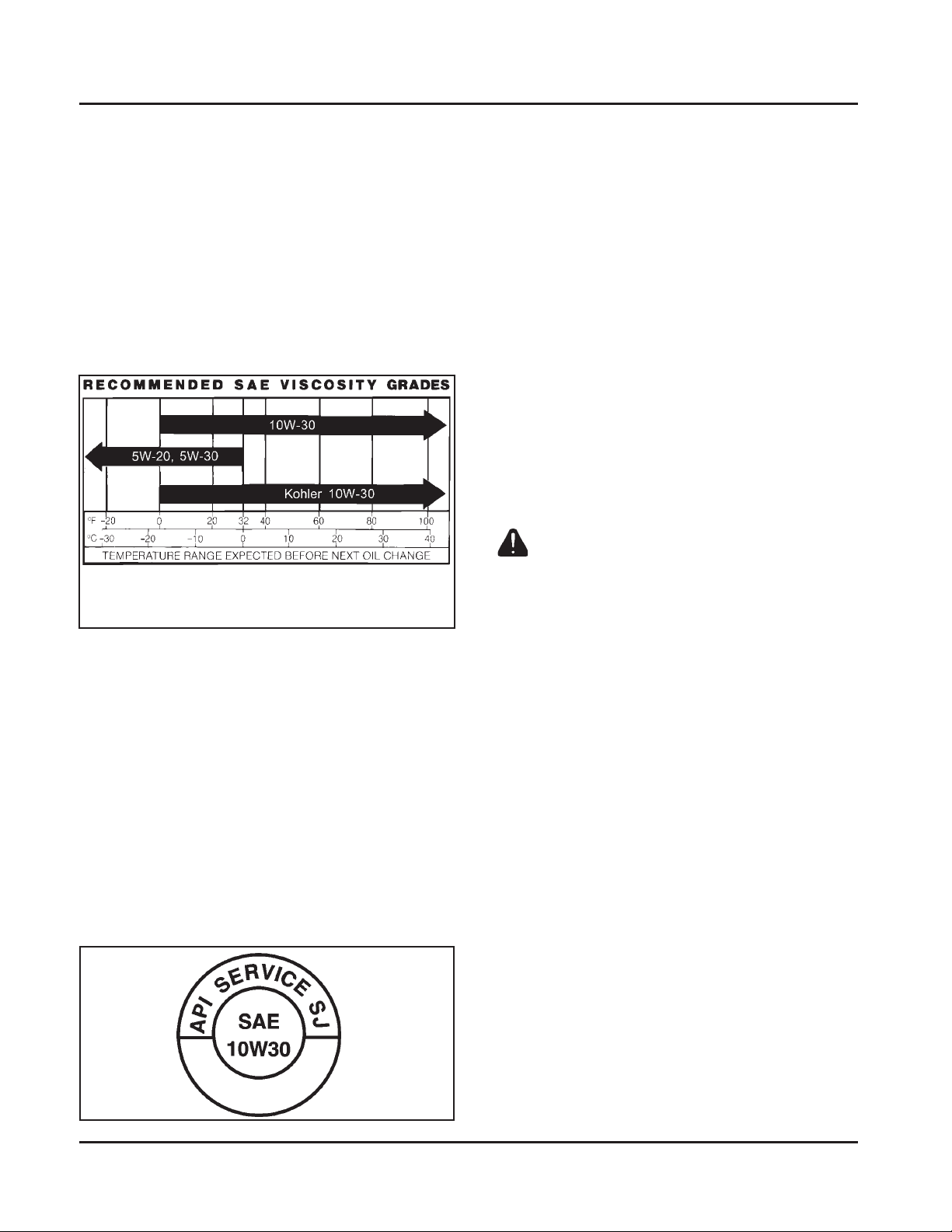
Oil Recommendations
Using the proper type and weight of oil in the
crankcase is extremely important. So is checking oil
daily and changing oil regularly. Failure to use the
correct oil, or using dirty oil, causes premature engine
wear and failure.
Oil T ype
Use high-quality detergent oil of API (American
Petroleum Institute) Service Class SG, SH, SJ or
higher. Select the viscosity based on the air
temperature at the time of operation as shown in the
following table.
**
*Use of synthetic oil having 5W-20 or 5W-30 rating is acceptable,
up to 4°C (40°F).
**Synthetic oils will provide better starting in extreme cold below
23°C (-10°F).
NOTE: Using other than service class SG, SH, SJ or
higher oil or extending oil change intervals
longer than recommended can cause engine
damage.
*
Refer to Section 6 - “Lubrication System” for detailed
procedures on checking the oil, changing the oil and
changing the oil filter.
Coolant Recommendations
Use equal parts of ethylene glycol and water only.
Distilled or deionized water is recommended,
especially in areas where the water contains a high
mineral content. Propylene glycol based antifreeze is
not recommended.
This mixture will provide protection from -37°C
(-34°F) to 108°C (226°F). For protection and use
outside the indicated temperature limits, follow the
antifreeze manufacturer's instructions on the
container, but do not exceed 70% antifreeze.
DO NOT use antifreeze with stop-leak additive(s), or
put any other additives in the cooling system.
Fuel Recommendations
WARNING: Explosive Fuel!
Gasoline is extremely flammable and its vapors can explode
if ignited. Store gasoline only in approved containers, in
well ventilated, unoccupied buildings, away from sparks or
flames. Do not fill the fuel tank while the engine is hot or
running, since spilled fuel could ignite if it comes in contact
with hot parts or sparks from ignition. Do not start the
engine near spilled fuel. Never use gasoline as a cleaning
agent.
NOTE: Synthetic oils meeting the listed
classifications may be used with oil changes
performed at the recommended intervals.
However to allow piston rings to properly
seat, a new or rebuilt engine should be
operated for at least 50 hours using standard
petroleum based oil before switching to
synthetic oil.
A logo or symbol on oil containers identifies the API
service class and SAE viscosity grade. See Figure 1-3.
Figure 1-3. Oil Container Logo.
1.4
General Recommendations
Purchase gasoline in small quantities and store in
clean, approved containers. A container with a
capacity of 2 gallons or less with a pouring spout is
recommended. Such a container is easier to handle
and helps eliminate spillage during refueling.
Do not use gasoline left over from the previous
season, to minimize gum deposits in your fuel system
and to ensure easy starting.
Do not add oil to the gasoline.
Do not overfill the fuel tank. Leave room for the fuel
to expand.
Fuel Type
For best results, use only clean, fresh, unleaded
gasoline with a pump sticker octane rating of 87 or
higher. In countries using the Research method, it
should be 90 octane minimum.
Section 1
Safety and General Information
Unleaded gasoline is recommended as it leaves less
combustion chamber deposits and reduces harmful
exhaust emissions. Leaded gasoline is not
recommended and must not be used on EFI engines,
or on other models where exhaust emissions are
regulated.
Gasoline/Alcohol blends
Gasohol (up to 10% ethyl alcohol, 90% unleaded
gasoline by volume) is approved as a fuel for Kohler
engines. Other gasoline/alcohol blends are not
approved.
Gasoline/Ether blends
Methyl Tertiary Butyl Ether (MTBE) and unleaded
gasoline blends (up to a maximum of 15% MTBE by
volume) are approved as a fuel for Kohler engines.
Other gasoline/ether blends are not approved.
Periodic Maintenance
WARNING: Accident al Starts!
Disabling engine. Accidental starting can cause severe injury or death. Before working on the engine or equipment,
disable the engine as follows: 1) Disconnect the spark plug lead(s). 2) Disconnect negative (-) battery cable from battery.
Maintenance Schedule
These required maintenance procedures should be performed at the frequency stated in the table. They should
also be included as part of any seasonal tune-up.
Frequency
Daily or Before
Starting Engine
Every 100 Hours
Annually or
Every 200 Hours
Every 250 Hours
Annually or
Every 500 Hours
Every 2 Y ears or
Every 1000 Hours
Every 1500 Hours
1
Perform these maintenance procedures more frequently under extremely dusty, dirty conditions.
Maintenance Required
• Fill fuel tank.
• Check oil level.
• Check coolant level.
• Check air cleaner for dirty1, Loose, or damaged parts.
• Check the screen, radiator, and cooling areas, clean as necessary1.
• Clean and check cooling areas1.
• Change oil and oil filter (more frequently under severe conditions).
• Check spark plug condition and gap.
• Change fuel filter (carbureted models).
• Replace spark plugs.
• Change engine coolant.
• Replace fuel filter1 (EFI engines).
Refer to:
Section 5
Section 6
Section 7
Section 4
Section 7
Section 7
Section 6
Section 5
Section 8
Section 4• Replace air cleaner element and check inner element1.
Section 8
Section 7
Section 5B
1
1.5

Section 1
Safety and General Information
Storage
If the engine will be out of service for two months or
more, use the following storage procedure:
1. Clean the exterior surfaces of the radiator and
engine. On EFI engines, avoid spraying water at
the wiring harness or any of the electrical
components.
2. Change the oil and filter while the engine is still
warm from operation. See “Change Oil and
Filter” in Section 6.
3. The coolant (anti-freeze) mixture should be in
good condition and tested to guard against
freezing in cold temperatures. The recommended
50/50 mixture will normally provide protection
down to temperatures of -37°C (-34°F). If storage
temperatures will fall below this, the cooling
system should be drained completely. A note
should then be attached to the equipment and/or
engine as a reminder to refill the cooling system
before starting.
4. The fuel system must be completely emptied, or
the gasoline must be treated with a stabilizer to
prevent deterioration. If you choose to use a
stabilizer, follow the manufacturers
recommendations, and add the correct amount
for the capacity of the fuel system. Fill the fuel
tank with clean, fresh gasoline. Run the engine
for 2-3 minutes to get stabilized fuel into the
carburetor. Close fuel shut-off valve when unit is
being stored or transported.
To empty the system, run the engine until the
tank and system are empty.
5. Remove the spark plugs. Add one tablespoon of
engine oil into each spark plug hole. Install plugs,
but do not connect the plug leads. Crank the
engine two or three revolutions.
6. On units with EFI engines, disconnect the
negative (-) battery cable or use a "battery
minder" trickle charger while the unit is in
storage.
7. Store the engine in a clean, dry place.
1.6
Section 1
Safety and General Information
Fuel Pump
23
Rain Cap Removal
(0.906)
C
Mounting Hole
L
Flywheel End
440.00
(17.323)
2X 184.20
(7.252)
458.49
(18.051)
Overall
C
Mounting Hole
L
127.90
(5.035)
622.54
(24.509)
Overall without Rain Cap
673.70
(26.524)
Overall
Optional Oil Fill
152.08
(5.987)
PTO Side
Oil
Drain
143.25
(5.640)
38.00
(1.496)
175.41
(6.906)
C
Mounting Hole "A"
L
Oil Filter Side
1
119.78
Fill
431.61
(16.992)
(4.716)
39.00
(1.535)
Oil Fill
89.00
(3.504)
Mounting Holes
C
Mounting Hole "A"
L
Starter Side
Air Intake Optional Orientation
583.30
(22.965)
490.74
(19.320)
Center of Air Intake
Engine Mounting Surface
120.96
(4.762)
Coolant
Overflow
38.00
(1.496)
C
Oil Drain Plug
L
238.61
(9.394)
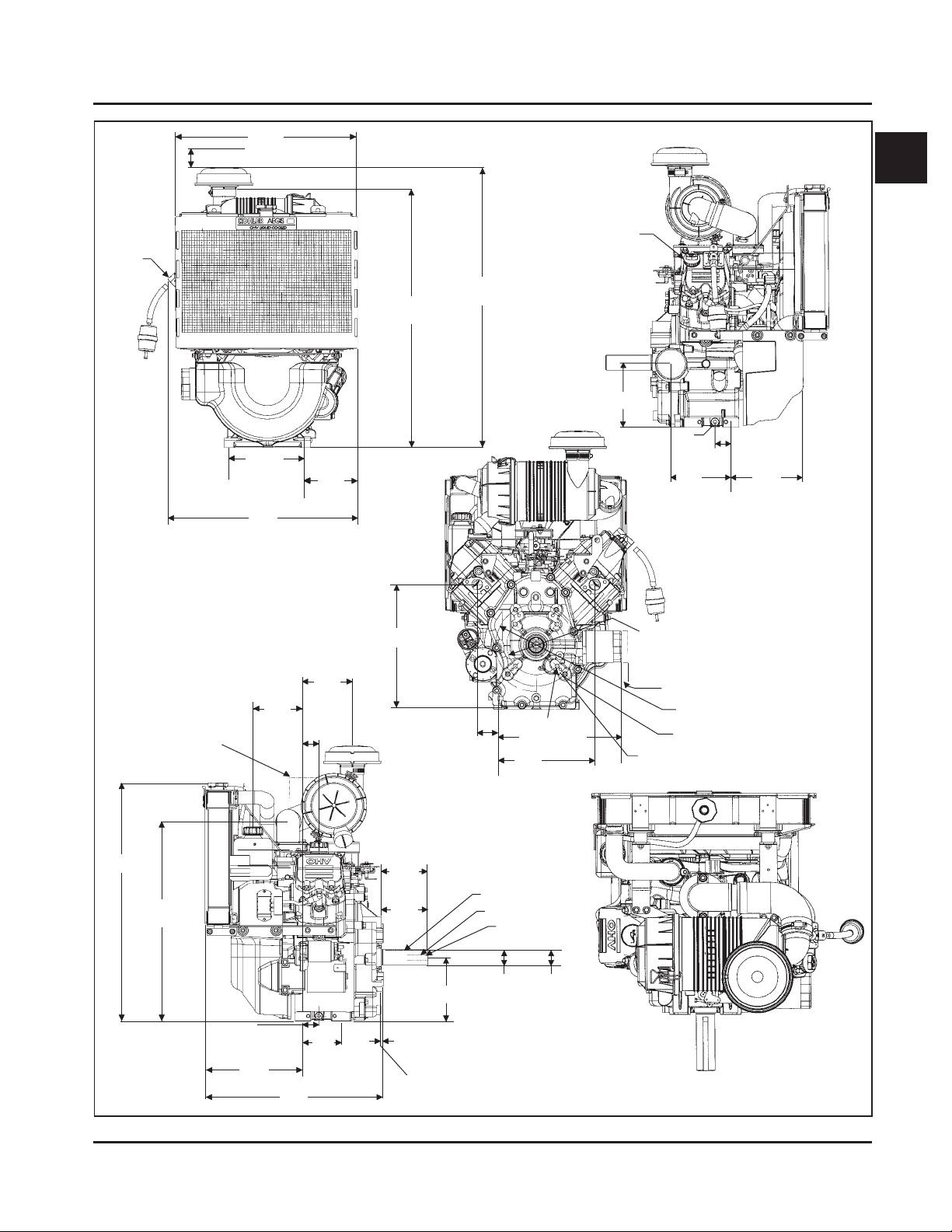
Figure 1-4. T ypical Engine Dimensions.
2X 297.47
(1.711)
Exhaust Ports
101.60
(4.000)
Option
112.92
(4.446)
4.00
(.157)
Mounting Surface
Pilot
155.58
(6.125)
4X 45°
50.99
(2.007)
Mounting Hole "A"
1/4 Inch Square Key
5/8-18 UNF Thread
7/16-20 Thread Option
36.50
(1.437)
C
L
2X 60°
2X 45°
4X 3/8-16 UNC-2B Inch
Oil Filter
299.00
(11.77)
235.19
(9.259)
28.575
Option
(1.125)
142.88 Bolt Circle
(5.625)
15.70 Oil Filter Removal
(0.618)
Bolt Circle 197.00
4x 7/16-14 UNC-2B Inch
177.80 Pilot
(7.000)
(7.756)
Top View
Dimensions in millimeters.
Inch equivalents shown in ().
1.7

Section 1
Safety and General Information
General Specifications
1
Power (@3600 RPM, exceeds Society of Automotive Engineers-Small Engine Test Code J1940.)
LH630 ................................................................................................................ Maximum ............... 16.4 kW (22 HP)
Recommended ...... 13.9 kW (18.7 HP)
LH640 ................................................................................................................ Maximum ............... 17.9 kW (24 HP)
Recommended ...... 15.2 kW (20.4 HP)
LH685 ................................................................................................................ Maximum ............... 18.6 kW (25 HP)
Recommended ...... 15.9 kW (21.3 HP)
LH690 ................................................................................................................ Maximum ............... 19.4 kW (26 HP)
Recommended ...... 16.5 kW (22.1 HP)
LH750 ................................................................................................................ Maximum ............... 20.1 kW (27 HP)
Recommended ...... 17.1 kW (22.9 HP)
LH755 ................................................................................................................ Maximum ............... 20.9 kW (28 HP)
Recommended ...... 17.7 kW (23.8 HP)
LH760 ................................................................................................................ Maximum ............... 21.6 kW (29 HP)
Recommended ...... 18.4 kW (24.7 HP)
LH775 ................................................................................................................ Maximum ............... 23.1 kW (31 HP)
Recommended ...... 19.7 kW (26.4 HP)
Peak Torque
LH630 @ 2200 RPM ...................................................................................................................... 48.0 N·m (35.4 ft. lb.)
LH640 @ 2400 RPM ...................................................................................................................... 51.9 N·m (38.3 ft. lb.)
LH685 @ 2200 RPM ...................................................................................................................... 54.3 N·m (40.1 ft. lb.)
LH690 @ 2400 RPM ...................................................................................................................... 58.1 N·m (42.9 ft. lb.)
LH750 @ 2200 RPM ...................................................................................................................... 61.0 N·m (45 ft. lb.)
LH755 @ 2800 RPM ...................................................................................................................... 61.5 N·m (45.4 ft. lb.)
LH760 @ 2600 RPM ...................................................................................................................... 61.7 N·m (45.5 ft. lb.)
LH775 @ 2400 RPM ...................................................................................................................... 64.6 N·m (47.7 ft. lb.)
Bore
LH630,LH640 ................................................................................................................................ 77 mm (3.03 in.)
LH685,LH690 ................................................................................................................................ 80 mm (3.15 in.)
LH750,LH755,LH760,LH775 ....................................................................................................... 83 mm (3.3 in.)
Stroke
LH630,LH640,LH685,LH690 ....................................................................................................... 67 mm (2.64 in.)
LH750,LH755,LH760,LH775 ....................................................................................................... 69 mm (2.7 in.)
Displacement
LH630,LH640 ................................................................................................................................ 624 cc (38.1 cu. in.)
LH685,LH690 ................................................................................................................................ 674 cc (41.1 cu. in.)
LH750,LH755,LH760,LH775 ....................................................................................................... 747 cc (45.6 cu. in.)
1
Values are in Metric units. Values in parentheses are English equivalents. Lubricate threads with engine oil prior
to assembly.
NOTE: All listed dimensions and tolerances are measured at 20°C (68°F).
1.8

Section 1
Safety and General Information
General Specifications1cont.
Compression Ratio
LH630,LH640,LH685,LH690 ............................................................................ 8.5:1
LH750,LH755,LH760,LH775 ............................................................................ 8.7:1
Dry Weight
LH630,LH640,LH685,LH690,LH755 ............................................................... 51.7 kg (114 lb.)
LH760,LH775 ..................................................................................................... 52.6 kg (116 lb.)
Oil Capacity (w/filter) - approximate,
determined by oil filter used: .................................................................................. 1.6-1.8 L (1.7-1.9 U.S. qt.)
Coolant Capacity (equal parts of water and ethylene glycol) ............................ 2.0 L (2.18 U.S. qt.)
Angle of Operation - Maximum (At Full Oil Level) All Directions .................. 20°
Camshaft
End Play (With Shim)............................................................................................... 0.076/0.127 mm (0.0030/0.0050 in.)
Running Clearance ................................................................................................... 0.025/0.063 mm (0.0010/0.0025 in.)
1
Bore I.D.
New ..................................................................................................................... 20.000/20.025 mm (0.7874/0.7884 in.)
Max. Wear Limit ................................................................................................ 20.038 mm (0.7889 in.)
Camshaft Bearing Surface O.D.
New ..................................................................................................................... 19.962/19.975 mm (0.7859/0.7864 in.)
Max. Wear Limit ................................................................................................ 19.959 mm (0.7858 in.)
Carburetor and Intake Manifold
Intake Manifold Fastener Torque (torque in 2 increments) ................................ first to 7.4 N·m (66 in. lb.)
finally to 9.9 N·m (88 in. lb.)
Thermostat Housing Mounting Fastener Torque ................................................. 6.2-7.3 N·m (55-65 in. lb.)
Carburetor Mounting Fastener Torque.................................................................. 9.9 N·m (88 in. lb.)
Connecting Rod
Cap Fastener Torque (torque in increments) ........................................................ 11.3 N·m (100 in. lb.)
Connecting Rod-to-Crankpin Running Clearance
New ..................................................................................................................... 0.043/0.068 mm (0.0016/0.0026 in.)
Max. Wear Limit ................................................................................................ 0.083 mm (0.0032 in.)
Connecting Rod-to-Crankpin Side Clearance ...................................................... 0.26/0.63 mm (0.0102/0.0248 in.)
Connecting Rod-to-Piston Pin Running Clearance.............................................. 0.015/0.028 mm (0.0006/0.0011 in.)
Piston Pin End I.D.
New ..................................................................................................................... 17.015/17.023 mm (0.6699/0.6702 in.)
Max. Wear Limit ................................................................................................ 17.036 mm (0.6707 in.)
1
Values are in Metric units. Values in parentheses are English equivalents. Lubricate threads with engine oil prior
to assembly.
1.9

Section 1
Safety and General Information
Crankcase
Governor Cross Shaft Bore I.D.
New .............................................................................................................. 8.025/8.075 mm (0.3159/0.3179 in.)
Max. Wear Limit ......................................................................................... 8.088 mm (0.3184 in.)
Breather Cover Fastener Torque ...................................................................... 10.7 N·m (95 in. lb.) into new hole
7.3 N·m (65 in. lb.) into used hole
Oil Drain Plug Torque ....................................................................................... 13.6 N·m (10 ft. lb.)
Closure Plate
Closure Plate Fastener Torque ......................................................................... 24.4 N·m (216 in. lb.)
Crankshaft
End Play (free) .................................................................................................... 0.070/0.590 mm (0.0028/0.0230 in.)
Crankshaft Sleeve Bearing I.D. (crankcase)
New .............................................................................................................. 40.974/40.987 mm (1.6131/1.6136 in.)
Max. Wear Limit ......................................................................................... 41.000 mm (1.6141 in.)
Crankshaft Bore (in closure plate)
New .............................................................................................................. 40.974/41.000 mm (1.6131/1.6141 in.)
Max. Wear Limit ......................................................................................... 41.038 mm (1.6156 in.)
Crankshaft Bore (in closure plate)-to-Crankshaft
Running Clearance - New ......................................................................... 0.039/0.087 mm (0.0015/0.0034 in.)
Main Bearing Journals
O.D. - New ................................................................................................... 40.913/40.935 mm (1.6107/1.6116 in.)
O.D. - Max. Wear Limit.............................................................................. 40.84 mm (1.608 in.)
Max. Taper ................................................................................................... 0.022 mm (0.0009 in.)
Max. Out-of-Round .................................................................................... 0.025 mm (0.0010 in.)
Crankshaft to Sleeve Bearing (crankcase)
Running Clearance - New ......................................................................... 0.039/0.074 mm (0.0015/0.0029 in.)
Connecting Rod Journal
O.D. - New ................................................................................................... 35.955/35.973 mm (1.4156/1.4163 in.)
O.D. - Max. Wear Limit.............................................................................. 35.94 mm (1.415 in.)
Max. Taper ................................................................................................... 0.018 mm (0.0007 in.)
Max. Out-of-Round .................................................................................... 0.025 mm (0.0010 in.)
Crankshaft T.I.R.
PTO End, Crank in Engine ........................................................................ 0.15 mm (0.0059 in.)
Entire Crank, in V-Blocks .......................................................................... 0.10 mm (0.0039 in.)
Cylinder Bore
Cylinder Bore I.D.
New
LH630,LH640 ........................................................................................... 77.000/77.025 mm (3.0315/3.0325 in.)
LH685,LH690 ........................................................................................... 80.000/80.025 mm (3.1496/3.1506 in.)
LH750,LH755,LH760,LH775 ................................................................. 83.006/83.031 mm (3.2679/3.2689 in.)
1.10

Section 1
Safety and General Information
Cylinder Bore cont.
Max. Wear Limit
LH630,LH640 .......................................................................................................77.063 mm (3.0340 in.)
LH685,LH690 .......................................................................................................80.065 mm (3.1522 in.)
LH750,LH755,LH760,LH775 .............................................................................83.069 mm (3.2704 in.)
Max. Out-of-Round ................................................................................................0.12 mm (0.0047 in.)
Max. Taper ............................................................................................................... 0.05 mm (0.0020 in.)
Cylinder Head
Cylinder Head Fastener Torque (torque in 2 increments) .......................................first to 16.9 N·m (150 in. lb.)
finally to 33.9 N·m (300 in. lb.)
Max. Out-of-Flatness ..................................................................................................... 0.076 mm (0.003 in.)
Rocker Pivot Fastener Torque ...................................................................................... 11.3 N·m (100 in. lb.)
Electric Starter
Starter Thru Bolt Torque ............................................................................................... 5.6-9.0 N·m (49-79 in. lb.)
Starter Mounting Screw Torque .................................................................................. 15.3 N·m (135 in. lb.)
1
Starter Brush Holder Fastener Torque ........................................................................ 2.5-3.3 N·m (22-29 in. lb.)
Starter Solenoid Fastener Torque ................................................................................ 4.0-6.0 N·m (35-53 in. lb.)
Starter Solenoid Positive (+) Brush Lead Retaining Nut Torque ............................ 8.0-11.0 N·m (71-97 in. lb.)
Fan/Flywheel
Rear Fan Shaft to Mounting Bracket Nut Torque ......................................................15.8 N·m (140 in. lb.)
Front Fan Assembly to Fan Shaft Nut Toque .............................................................15.8 N·m (140 in. lb.)
Fan/Pulley/Hub Assembly Fastener Torque ..............................................................6.8 N·m (60 in. lb.)
Flywheel Retaining Screw Torque ...............................................................................66.4 N·m (49 ft. lb.)
Lower Flywheel Cover Mounting Screw Torque ...................... into hex or weld nuts 9.9 N·m (88 in. lb.)
into Timmerman clips/nuts 2.2-2.8 N·m (20-25 in. lb.)
Lower Pulley Mounting Screw Torque ...................................................................... 24.3 N·m (215 in. lb.)
Governor
Governor Cross Shaft to Crankcase Running Clearance.......................................... 0.025/0.126 mm (0.0009/0.0049 in.)
Governor Cross Shaft O.D.
New .......................................................................................................................... 7.949/8.000 mm (0.3129/0.3149 in.)
Max. Wear Limit .....................................................................................................7.936 mm (0.3124 in.)
Governor Gear Shaft O.D.
New .......................................................................................................................... 5.990/6.000 mm (0.2358/0.2362 in.)
Max. Wear Limit .....................................................................................................5.977 mm (0.2353 in.)
Governor Gear Shaft-to-Governor Gear Running Clearance .................................. 0.090/0.160 mm (0.0035/0.0063 in.)
Governor Lever Nut Torque......................................................................................... 6.8 N·m (60 in. lb.)
1.11

Section 1
Safety and General Information
Ignition
Spark Plug Type (Champion
Spark Plug Gap ........................................................................................................ 0.76 mm (0.030 in.)
Spark Plug Torque ................................................................................................... 24.4-29.8 N·m (18-22 ft. lb.)
Ignition Module Air Gap ........................................................................................ 0.203/0.305 mm (0.008/0.012 in.)
Ignition Module Fastener Torque .......................................................................... 6.2 N·m (55 in. lb.) into new hole
Rectifier-Regulator Fastener Torque ..................................................................... 4.0 N·m (35 in. lb.)
Muffler
Muffler Retaining Nuts Torque ............................................................................. 24.4 N·m (216 in. lb.)
Oil Filter
Oil Filter Torque....................................................................................................... 3/4-1 turn after gasket contact
Piston, Piston Rings, and Piston Pin
Piston-to-Piston Pin ................................................................................................. 0.006/0.018 mm (0.0002/0.0007 in.)
Piston Pin Bore I.D.
New .................................................................................................................... 17.006/17.013 mm (0.6695/0.6698 in.)
Max. Wear Limit ............................................................................................... 17.025 mm (0.6703 in.)
®
or equivalent)....................................................... RC14YC
4.0 N·m (35 in. lb.) into used hole
Piston Pin O.D.
New .................................................................................................................... 16.995/17.000 mm (0.6691/0.6693 in.)
Max. Wear Limit ............................................................................................... 16.994 mm (0.6691 in.)
Top Compression Ring-to-Groove Side Clearance
LH630,LH640 .................................................................................................... 0.040/0.086 mm (0.0016/0.0034 in.)
LH685,LH690 .................................................................................................... 0.050/0.096 mm (0.0020/0.0038 in.)
LH750,LH755,LH760,LH775 ........................................................................... 0.014/0.041 mm (0.0005/0.0016 in.)
Middle Compression Ring-to-Groove Side Clearance
LH630,LH640 .................................................................................................... 0.040/0.086 mm (0.0016/0.0034 in.)
LH685,LH690 .................................................................................................... 0.030/0.076 mm (0.0012/0.0030 in.)
LH750,LH755,LH760,LH775 ........................................................................... 0.012/0.039 mm (0.0004/0.0015 in.)
Oil Control Ring-to-Groove Side Clearance
LH630,LH640 .................................................................................................... 0.046/0.196 mm (0.0018/0.0077 in.)
LH685,LH690 .................................................................................................... 0.046/0.196 mm (0.0018/0.0077 in.)
LH750,LH755,LH760,LH775 ........................................................................... 0.026/0.176 mm (0.0010/0.0070 in.)
Top and Middle Compression Ring End Gap
LH630,LH640
New Bore
Top Ring ......................................................................................................... 0.180/0.380 mm (0.0071/0.0150 in.)
Middle Ring ................................................................................................... 0.250/0.450 mm (0.0098/0.0177 in.)
Used Bore (Max.) ............................................................................................. 0.77 mm (0.030 in.)
²Measure 6 mm (0.236 in.) above the bottom of the piston skirt at right angles to the piston pin.
1.12

Piston, Piston Rings, and Piston Pin cont.
Top and Middle Compression Ring End Gap cont.
LH685,LH690
New Bore
Top Ring ..................................................................................... 0.180/0.430 mm (0.0071/0.0169 in.)
Middle Ring ............................................................................... 0.250/0.460 mm (0.0098/0.0181 in.)
Used Bore (Max.).............................................................................. 0.80 mm (0.0315 in.)
LH750,LH755,LH760 LH775
New Bore ........................................................................................... 0.250/0.56 mm (0.0098/0.022 in.)
Used Bore .......................................................................................... 0.94 mm (0.037 in.)
Piston Thrust Face O.D.²
LH630,LH640
New ....................................................................................................76.968/76.986 mm (3.0302/3.0309 in.)
Max. Wear Limit ...............................................................................76.840 mm (3.0252 in.)
LH685,LH690
New ....................................................................................................79.963/79.981 mm (3.1481/3.1488 in.)
Max. Wear Limit ...............................................................................79.831 mm (3.1430 in.)
LH750,LH755,LH760 LH775
New ....................................................................................................82.973/82.991 mm (3.2666/3.2673 in.)
Max. Wear Limit ...............................................................................82.841 mm (3.3136 in.)
Section 1
Safety and General Information
1
Piston Thrust Face-to-Cylinder Bore² Running Clearance
LH630,LH640 ...........................................................................................0.014/0.057 mm (0.0005/0.0022 in.)
LH685,LH690 ...........................................................................................0.019/0.062 mm (0.0007/0.0024 in.)
LH750,LH755,LH760 LH775 ..................................................................0.015/0.058 mm (0.005/0.0022 in.)
Speed Control
Speed Control Bracket Assembly Fastener Torque .................................... 10.7 N·m (95 in. lb.) into new holes
7.3 N·m (65 in. lb.) into used holes
Stator
Stator Mounting Screw Torque .....................................................................6.2 N·m (55 in. lb.)
Valve Cover/Rocker Arms
Valve Cover Fastener Torque ........................................................................ 6.2 N·m (55 in. lb.)
Valves and Valve Lifters
Hydraulic Valve Lifter to Crankcase Running Clearance ......................... 0.0124/0.0501 mm (0.0005/0.0020 in.)
Intake Valve Stem-to-Valve Guide Running Clearance............................. 0.038/0.076 mm (0.0015/0.0030 in.)
Exhaust Valve Stem-to-Valve Guide Running Clearance ..........................0.050/0.088 mm (0.0020/0.0035 in.)
Intake Valve Guide I.D.
New ........................................................................................................... 7.038/7.058 mm (0.2771/0.2779 in.)
Max. Wear Limit ...................................................................................... 7.134 mm (0.2809 in.)
Intake Valve Stem Diameter
New ........................................................................................................... 6.982/7.000 mm (0.2749/0.2756 in.)
Exhaust Valve Guide I.D.
New ........................................................................................................... 7.038/7.058 mm (0.2771/0.2779 in.)
Max. Wear Limit ...................................................................................... 7.159 mm (0.2819 in.)
²Measure 6 mm (0.236 in.) above the bottom of the piston skirt at right angles to the piston pin.
1.13
Section 1
Safety and General Information
Valves and Valve Lifters cont.
Exhaust Valve Stem Diameter
New ......................................................................................................................... 6.970/6.988 mm (0.2744/0.2751 in.)
Valve Guide Reamer Size
Standard ..................................................................................................................7.048 mm (0.2775 in.)
0.25 mm O.S. ........................................................................................................... 7.298 mm (0.2873 in.)
Intake Valve Lift ............................................................................................................ 8.88 mm (0.3496 in.)
Exhaust Valve Lift ......................................................................................................... 8.88 mm (0.3496 in.)
Nominal Valve Seat Angle ........................................................................................... 45°
Water Pump
Mounting Screw Torque .............................................................................................. 9.9 N·m (88 in. lb.)
Pulley Mounting Screw Torque .................................................................................. 9.9 N·m (88 in. lb.)
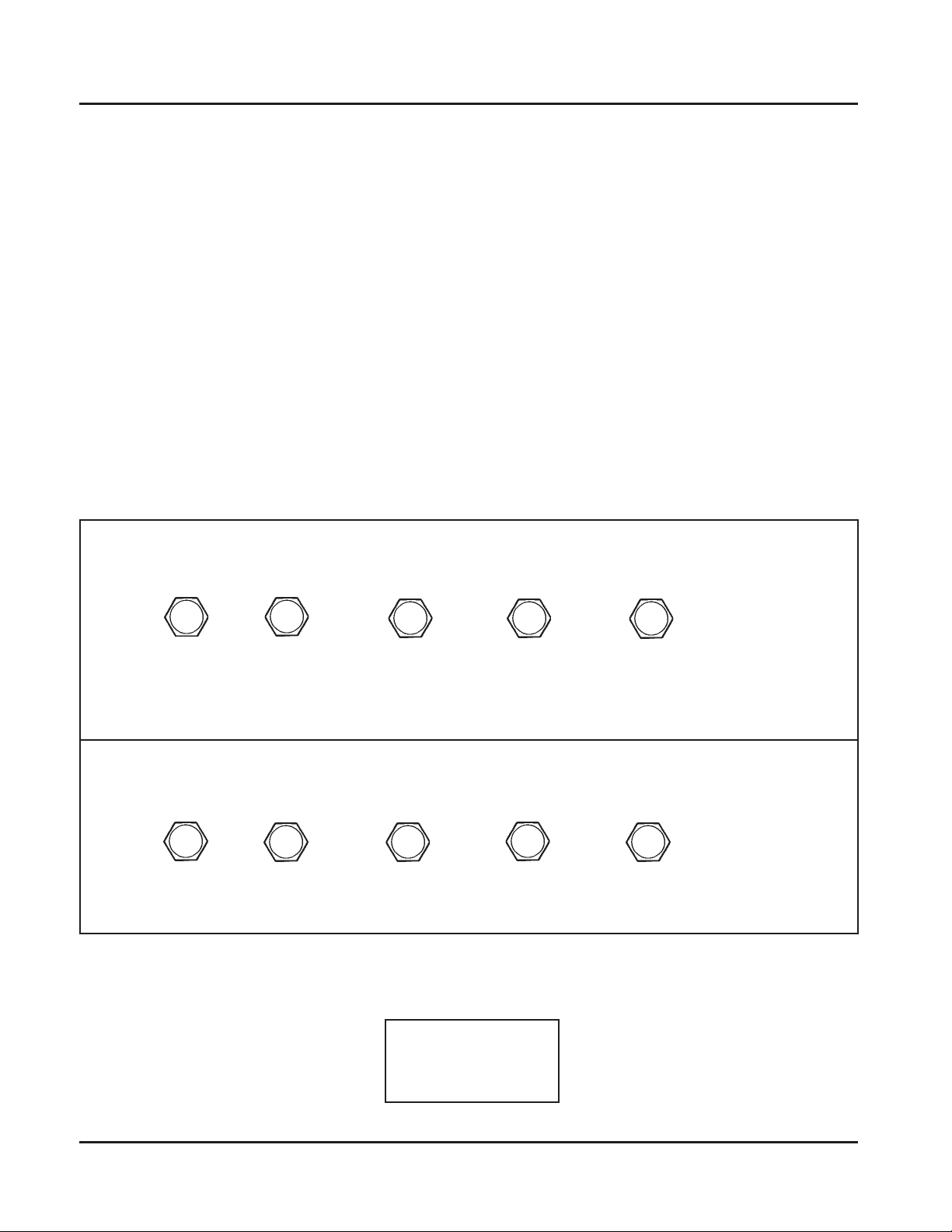
General Torque Values
Metric Fastener T orque Recommendations for St andard Applications
Tightening Torque: N·m (in. lb.) + or - 20%
Property Class
Noncritical
4.8
Size
M4 1.2 (11) 1.7 (15) 2.9 (26) 4.1 (36) 5.0 (44) 2.0 (18)
M5 2.5 (22) 3.2 (28) 5.8 (51) 8.1 (72) 9.7 (86) 4.0 (35)
M6 4.3 (38) 5.7 (50) 9.9 (88) 14.0 (124) 16.5 (146) 6.8 (60)
M8 10.5 (93) 13.6 (120) 24.4 (216) 33.9 (300) 40.7 (360) 17.0 (150)
5.8
8.8
10.9
12.9
Fasteners
Into Aluminum
Tightening Torque: N·m (ft. lb.) + or - 20%
Property Class
Noncritical
4.8
M10 21.7 (16) 27.1 (20) 47.5 (35) 66.4 (49) 81.4 (60) 33.9 (25)
M12 36.6 (27) 47.5 (35) 82.7 (61) 116.6 (86) 139.7 (103) 61.0 (45)
M14 58.3 (43) 76.4 (55) 131.5 (97) 184.4 (136) 219.7 (162) 94.9 (70)
5.8
8.8
10.9
12.9
Fasteners
Into Aluminum
Torque
Conversions
N·m = in. lb. x 0.113
N·m = ft. lb. x 1.356
in. lb. = N·m x 8.85
ft. lb. = N·m x 0.737
1.14
Safety and General Information
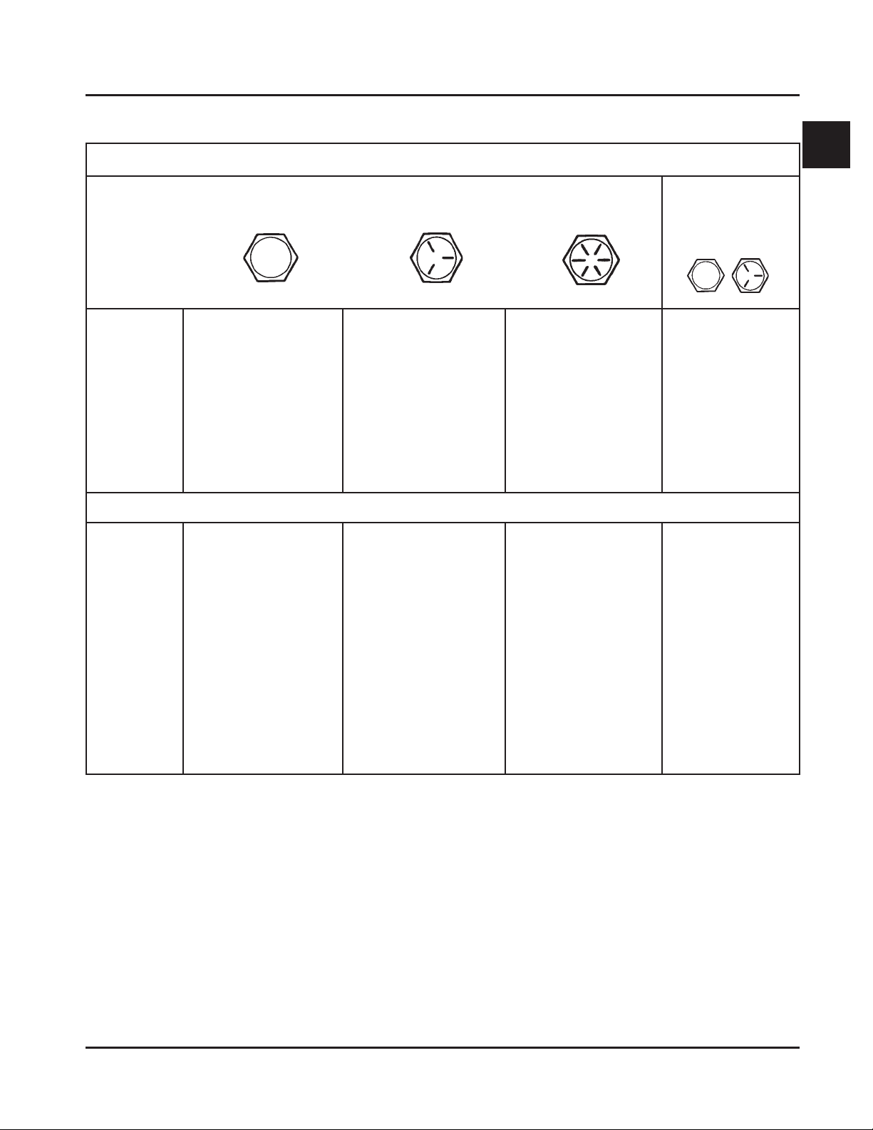
English Fastener Torque Recommendations for Standard Applications
Section 1
Tightening Torque: N·m (in. lb.) + or - 20%
Bolts, Screws, Nuts and Fasteners
Assembled Into Cast Iron or Steel
Grade 2 Grade 5 Grade 8
Size
8-32 2.3 (20) 2.8 (25) --------- 2.3 (20)
10-24 3.6 (32) 4.5 (40) --------- 3.6 (32)
10-32 3.6 (32) 4.5 (40) --------- ---------
1/4-20 7.9 (70) 13.0 (115) 18.7 (165) 7.9 (70)
1/4-28 9.6 (85) 15.8 (140) 22.6 (200) ---------
5/16-18 17.0 (150) 28.3 (250) 39.6 (350) 17.0 (150)
5/16-24 18.7 (165) 30.5 (270) --------- ---------
3/8-16 29.4 (260) --------- --------- ---------
3/8-24 33.9 (300) --------- --------- ---------
Grade 2 or 5
Fasteners Into
Aluminum
Tightening Torque: N·m (ft. lb.) + or - 20%
Size
5/16-24 --------- ---------- 40.7 (30) --------3/8-16 --------- 47.5 (35) 67.8 (50) --------3/8-24 --------- 54.2 (40) 81.4 (60) --------7/16-14 47.5 (35) 74.6 (55) 108.5 (80) --------7/16-20 61.0 (45) 101.7 (75) 142.4 (105) --------1/2-13 67.8 (50) 108.5 (80) 155.9 (115) --------1/2-20 94.9 (70) 142.4 (105) 223.7 (165) --------9/16-12 101.7 (75) 169.5 (125) 237.3 (175) --------9/16-18 135.6 (100) 223.7 (165) 311.9 (230) --------5/8-11 149.2 (110) 244.1 (180) 352.6 (260) --------5/8-18 189.8 (140) 311.9 (230) 447.5 (330) --------3/4-10 199.3 (150) 332.2 (245) 474.6 (350) --------3/4-16 271.2 (200) 440.7 (325) 637.3 (470) ---------
1
1.15
Section 2
Section 2
Tools & Aids
Tools & Aids
Certain quality tools are designed to help you perform specific disassembly, repair, and reassembly procedures.
By using tools designed for the job, you can properly service engines easier, faster, and safer! In addition, you’ll
increase your service capabilities and customer satisfaction by decreasing engine downtime.
Here is the list of tools and their source.
Separate Tool Suppliers:
Kohler Tools
Contact your source
of supply.
slooT
noitpircseD .oNtraP/ecruoS
SE Tools
415 Howard St.
Lapeer, MI 48446
Phone 810-664-2981
Toll Free 800-664-2981
Fax 810-664-8181
)seireSM&K(looTgnimiTraeGecnalaB
.enignegnilbmessanehwnoitisopdemitnisraegecnalabdlohoT
Design Technology Inc.
768 Burr Oak Drive
Westmont, IL 60559
Phone 630-920-1300
S-6055452relhoK
)753-YylremroF(
2
IFEtiKecivreS
etalPyalpdnEtfahsmaC
.yalpdnetfahsmacgnikcehcroF
retseTnwodkaeLrednilyC
.nrowerasevlavro,sgnir,notsip,rednilycfidnanoitneternoitsubmocgnikcehcroF
erawtfoScitsongaiD)IFE(noitcejnIleuFcinortcelE
.CPpotkseDropotpaLhtiwesU
.enigneIFEnapugnittesdnagnitoohselbuortroF
elbaliavAstnenopmoClaudividnI
retseTerusserP
thgiLdioN
retpadA°09
sreilPpmalCrekiteO
eriWdeR,gulPedoC
eriWeulB,gulPedoC
)seireSSC(looTgnidloHleehwylF 70428-RLKslooTES
relluPleehwylF
.enignemorfleehwylfevomeroT
50428-RLKslooTES
S-5016752relhoK
S-3216752relhoK
S-1016742relhoK
.cnIygolonhceTngiseD
910-ITD
120-ITD
320-ITD
520-ITD
720-ITD
920-ITD
80428-RLKslooTES
2.1
Section 2
Tools & Aids
).tnoc(slooT
noitpircseD .oNtraP/ecruoS
hcnerWpartSleehwylF
.lavomergnirudleehwylfdlohoT
looTretfiLevlaVciluardyH
.sretfilciluardyhllatsnidnaevomeroT
retseTmetsySnoitingI
.DCtpecxe,smetsysllanotuptuognitsetroF
.metsysnoitingi)DC(egrahcsideviticapacnotuptuognitsetroF
)seireSM&K(hcnerWtesffO
.stungniniaterlerrabrednilycllatsnierdnaevomeroT
tiKtseTerusserPliO
.erusserplioyfirevdnatsetoT
)tnerructlov021(retseTrotalugeR-reifitceR
)tnerructlov042(retseTrotalugeR-reifitceR
.srotaluger-reifitcertsetotdesU
elbaliavAstnenopmoClaudividnI
ssenraHtseTrotalugeRORP-SC
edoiDhtiwssenraHtseTrotalugeRlaicepS
retseT)MAS(eludoMecnavdAkrapS
KRAPS-TRAMShtiwsenigneno)MASDdnaMASA(MASehttsetoT
.™
)tfihSdioneloS(looTgnidloHhsurBretratS
.gnicivresgnirudsehsurbdlohoT
90428-RLKslooTES
S-8316752relhoK
S-1055452relhoK
S-2055442relhoK
01428-RLKslooTES
S-6016752relhoK
S-0216752relhoK
S-1416752relhoK
.cnIygolonhceTngiseD
130-ITD
330-ITD
S-0416752relhoK
61428-RLKslooTES
)evirDaitrenI(looTgniRgniniateRretratS
.)sretratsOCSAFgnidulcxe(sgnirgniniaterevirdllatsnierdnaevomeroT
)sretratSllA(tiKgnicivreSretratS
.sehsurbdnasgnirgniniaterevirdllatsnierdnaevomeroT
elbaliavAtnenopmoClaudividnI
)tfihSdioneloS(looTgnidloHhsurBretratS
)evitcudnIlatigiD(retemohcaT
.enignenafo)MPR(deepsgnitarepognikcehcroF
retseTerusserP/muucaV
.retemonamretawaotevitanretlA
)seireSM&K(remaeRediuGevlaV
.noitallatsniretfasediugevlavgnizisroF
)CHO,dnammoC,sigeA,egaruoC(tiKecivreSediuGevlaV
.sediugeulavnrowgnicivresroF
S-8116752relhoK
11428-RLKslooTES
61428-RLKslooTES
.cnIygolonhceTngiseD
011-ITD
S-2216752relhoK
31428-RLKslooTES
51428-RLKslooTES
2.2
Section 2
Tools & Aids
sdiA
noitpircseD .oNtraP/ecruoS
tnacirbuLtfahsmaC )316ZZrapslaV( S-4175352relhoK
esaerGcirtceleiD )166GdraugavoN/EG( S-1175352relhoK
esaerGcirtceleiD )orP-leF( leS-irbuL
tnacirbuLevirDretratScirtcelE )evirDaitrenI( S-1075325relhoK
tnacirbuLevirDretratScirtcelE )tfihSdioneloS(S-2075325relhoK
2
®
etitcoL
.resnepsidlosoreazo4niydoByvaeH0095
tnalaeSenociliSVTR
S-7079552relhoK
.esurofdevorppaera,detsilesohtsahcus,stnalaesVTRtnatsiserlio,desab-emixoylnO
®
etitcoL
®
etitcoL
0195
®
etitcoL
®
etitcoL
®
etitcoL
895kcalBartlU
785eulBartlU
reppoCartlU
.scitsiretcarahcgnilaestsebrofdednemmocerera0195ro0095.soN
tnacirbuLevirDenilpS S-2175352relhoK
2.3
Section 2
Tools & Aids
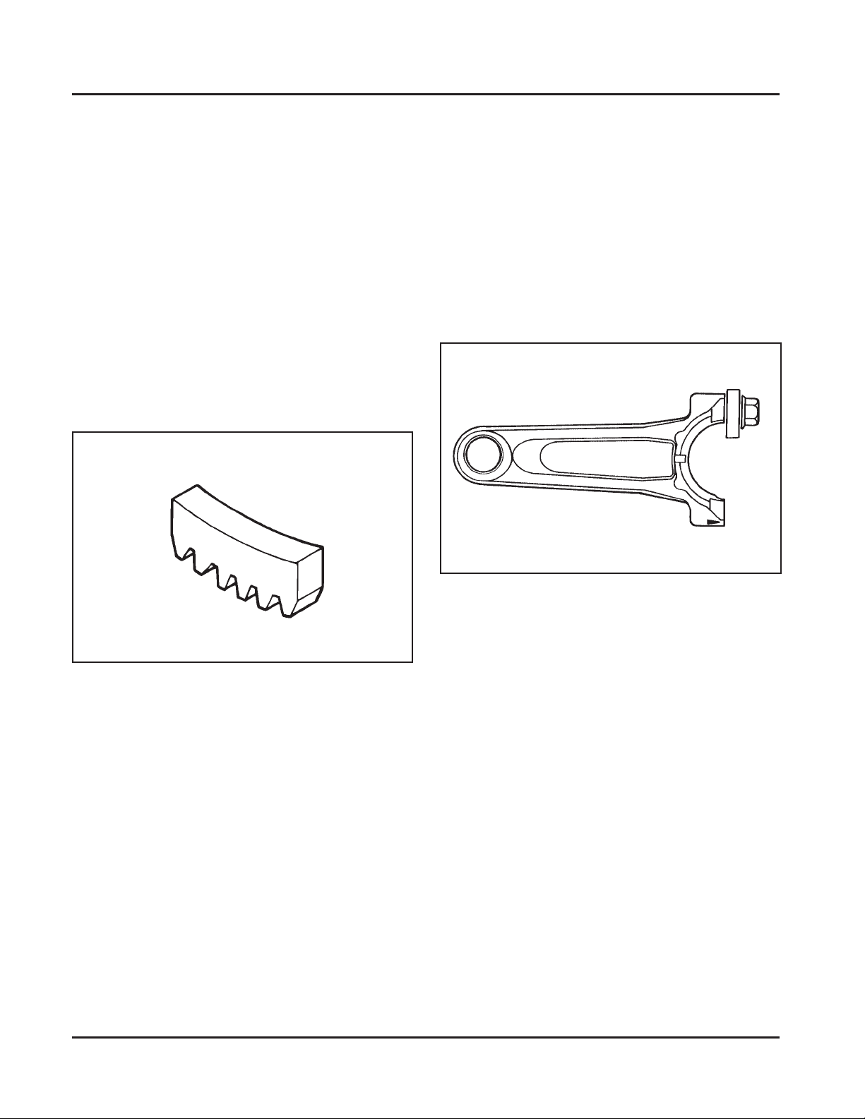
Special Tools You Can Make
Flywheel Holding Tool
A flywheel holding tool can be made out of an old
junk flywheel ring gear as shown in Figure 2-1, and
used in place of a strap wrench.
1. Using an abrasive cut-off wheel, cut out a six
tooth segment of the ring gear as shown.
2. Grind off any burrs or sharp edges.
3. Invert the segment and place it between the
ignition bosses on the crankcase so that the tool
teeth engage the flywheel ring gear teeth. The
bosses will lock the tool and flywheel in
position for loosening, tightening or removing
with a puller.
2. Remove the studs of a Posi-Lock rod or grind off
the aligning steps of a Command rod, so the joint
surface is flat.
3. Find a 1 in. long capscrew with the correct
thread size to match the threads in the
connecting rod.
4. Use a flat washer with the correct I.D. to slip on
the capscrew and approximately 1” O.D. (Kohler
Part No. 12 468 05-S). Assemble the capscrew
and washer to the joint surface of the rod, as
shown in Figure 2-2.
Figure 2-1. Flywheel Holding Tool.
Rocker Arm/Crankshaft Tool
A spanner wrench to lift the rocker arms or turn the
crankshaft may be made out of an old junk connecting
rod.
1. Find a used connecting rod from a 10 HP or
larger engine. Remove and discard the rod cap.
Figure 2-2. Rocker Arm/Crankshaf t T ool.
2.4
Section 3
Troubleshooting
Troubleshooting Guide
When troubles occur, be sure to check the simple
causes which, at first, may seem too obvious to be
considered. For example, a starting problem could be
caused by an empty fuel tank.
Some common causes of engine troubles are listed
below. Use these to locate the causing factors.
Engine Cranks But Will Not Start
1. Empty fuel tank.
2. Fuel shut-off valve closed.
3. Dirt or water in the fuel system.
4. Clogged fuel line.
5. Spark plug lead(s) disconnected.
6. Key switch or kill switch in “off” position.
7. Faulty spark plugs.
8. Faulty ignition module(s).
9. Carburetor solenoid malfunction.
10. Diode in wiring harness failed in open circuit
mode.
11. Vacuum fuel pump malfunction, or oil in vacuum
hose.
12. Vacuum hose to fuel pump leaking/cracked.
13. Battery connected backwards.
14. Safety interlock system engaged.
Engine Start s But Does Not Keep Running
1. Restricted fuel tank cap vent.
2. Poor fuel, dirt or water in the fuel system.
3. Faulty/misadjusted choke or throttle controls.
4. Loose wires or connections that short the kill
terminal of ignition module to ground.
5. Faulty cylinder head gasket.
6. Faulty carburetor.
7. Vacuum fuel pump malfunction, or oil in vacuum
hose.
8. Leaking/cracked vacuum hose to fuel pump.
9. Intake system leak.
10. Diode in wiring harness failed in open circuit
mode.
Section 3
Troubleshooting
3
Engines Start s Hard
1. PTO drive is engaged.
2. Dirt or water in the fuel system.
3. Clogged fuel line.
4. Loose or faulty wires or connections.
5. Faulty or misadjusted choke or throttle controls.
6. Faulty spark plugs.
7. Low compression.
8. Weak spark.
9. Fuel pump malfunction causing lack of fuel.
10. Engine overheated-cooling system problem.
11. Quality of fuel.
12. Flywheel key sheared.
13. Intake system leak.
Engine Will Not Crank
1. PTO drive is engaged.
2. Battery is discharged.
3. Safety interlock switch is engaged.
4. Loose or faulty wires or connections.
5. Faulty key switch or ignition switch.
6. Faulty electric starter or solenoid.
7. Seized internal engine components.
Engine Runs But Misses
1. Dirt or water in the fuel system.
2. Spark plug lead disconnected.
3. Loose wires or connections that intermittently
short the kill circuit of ignition system to ground.
4. Engine overheated-cooling system problem.
5. Faulty ignition module.
6. Faulty spark plugs.
7. Carburetor adjusted incorrectly.
8. Faulty interlock switch.
Engine Will Not Idle
1. Restricted fuel tank cap vent.
2. Dirt or water in the fuel system.
3. Faulty spark plugs.
4. Idle speed (RPM) adjusting screw improperly set.
5. Low compression.
6. Stale fuel and/or gum in carburetor.
7. Fuel supply inadequate.
8. Engine overheated-cooling system problem.
3.1

Section 3
Troubleshooting
Engine Overheats
1. Radiator, and/or cooling system components
clogged, restricted, or leaking.
2. Excessive engine load.
3. Low crankcase oil level.
4. Low cooling system fluid level.
5. High crankcase oil level.
6. Lean fuel mixture.
7. Fan belt failed/off.
8. Cooling fan broken.
9. Water pump belt failed/broken.
10. Water pump malfunction.
11. Faulty carburetor.
Engine Knocks
1. Excessive engine load.
2. Low crankcase oil level.
3. Old or improper fuel.
4. Internal wear or damage.
5. Hydraulic lifter malfunction.
6. Quality of fuel.
7. Incorrect grade of oil.
Engine Loses Power
1. Low crankcase oil level.
2. High crankcase oil level.
3. Dirty air cleaner element.
4. Dirt or water in the fuel system.
5. Excessive engine load.
6. Engine overheated. (See "Engine Overheats")
7. Faulty spark plugs.
8. Low compression.
9. Exhaust restriction.
10. Low battery.
11. Incorrect governor setting.
Engine Uses Excessive Amount Of Oil
1. Incorrect oil viscosity/type.
2. Clogged or improperly assembled breather.
3. Breather reed broken.
4. Worn or broken piston rings.
5. Worn cylinder bore.
6. Worn valve stems or valve guides.
7. Crankcase overfilled.
8. Blow head gasket/overtightened.
Engine Loses or Uses Coolant
1. Overheating-See "Engine Overheats".
2. External leakage-from a joint connection, or a
component of the cooling system.
3. Internal leakage-from a head gasket, or cooling
system water jacket (passage) leak.
External Engine Inspection
Before cleaning or disassembling the engine, make a
thorough inspection of its external appearance and
condition. This inspection can give clues to what might
be found inside the engine (and the cause) when it is
disassembled.
• Check for buildup of dirt and debris on the
radiator, crankcase, cooling system components,
and other external surfaces. Dirt or debris on these
areas are causes of higher operating temperatures
and overheating.
• Check for obvious fuel, oil, and coolant leaks, or
damaged components. Excessive oil leakage can
indicate a clogged or improperly assembled
breather, worn or damaged seals and gaskets, or
loose or improperly torqued fasteners. Coolant
leaks can cause higher operating temperatures and
overheating.
• Check the air cleaner assembly/components for
damage or indications of leakage.
• Check the air cleaner element and inner element.
Look for holes, tears, cracked/damaged sealing
surfaces, or other damage that could allow
unfiltered air into the engine. Also note if the
elements are dirty or clogged. These could
indicate that the engine has been underserviced.
• Check the carburetor throat for dirt. Dirt in the
throat is further indication that the air cleaner is
not functioning properly.
• Check the oil level. Note if the oil level is within
the operating range on the dipstick, or if it is low
or overfilled.
Oil Leaks from Oil Seals, Gaskets
1. Crankcase breather is clogged or inoperative.
2. Breather read broken.
3. Loose or improperly torqued fasteners.
4. Piston blowby or leaky valves.
5. Restricted exhaust.
3.2
• Check the coolant level within the reservoir and in
the radiator. A low or improperly filled cooling
system can cause overheating, excessive fuel
consumption, and a lack of power.
Section 3
Troubleshooting
• Check the condition of the oil. Drain the oil into a
container - the oil should flow freely. Check the
appearance (color) of the oil, and for metal chips
or foreign particles. A milky, opaque color denotes
the presence of engine coolant in the crankcase oil.
Sludge is a natural by-product of combustion;
a small accumulation is normal. Excessive
sludge formation could indicate overrich
carburetion, weak ignition, overextended oil
change intervals or wrong weight or type of oil
was used, to name a few.
NOTE: It is good practice to drain oil at a
location away from the workbench. Be
sure to allow ample time for complete
drainage.
Cleaning The Engine
After inspecting the external condition of the engine,
clean the engine thoroughly before disassembling it.
Also clean individual components as the engine is
disassembled. Only clean parts can be accurately
inspected and gauged for wear or damage. There are
many commercially available cleaners that will quickly
remove grease, oil, and grime from engine parts. When
such a cleaner is used, follow the manufacturer’s
instructions and safety precautions carefully.
Basic Engine Tests
Crankcase Vacuum Test
A partial vacuum should be present in the crankcase
when the engine is operating. Pressure in the
crankcase (normally caused by a clogged or
improperly assembled breather) can cause oil to be
forced out at oil seals, gaskets, or other available spots.
Crankcase vacuum is best measured with either a
water manometer or a vacuum gauge (see Section 2).
Complete instructions are provided in the kits.
Test the crankcase vacuum with the manometer as
follows:
1. Insert the stopper/hose into the oil fill hole. Leave
the other tube of manometer open to atmosphere.
Make sure the shut-off clamp is closed.
2. Start the engine and run at no-load full throttle
speed (3200 to 3750 RPM).
3. Open the clamp and note the water level in the
tube.
The level in the engine side should be a minimum
of 10.2 cm (4 in.) above the level in the open side.
3
Make sure all traces of the cleaner are removed before
the engine is reassembled and placed into operation.
Even small amounts of these cleaners can quickly break
down the lubricating properties of engine oil.
No Crankcase Vacuum/Pressure in Crankcase
Possible Cause Solution
1. Crankcase breather clogged or inoperative.
2. Seals and/or gaskets leaking. Loose or
improperly torqued fasteners.
3. Piston blowby or leaky valves. (Confirm by
inspecting components.)
4. Restricted exhaust.
If the level in the engine side is less than specified
(low/no vacuum), or the level in the engine side is
lower than the level in the open side (pressure),
check for the conditions in the table below.
4. Close the shut-off clamp before stopping the
engine.
1. Replace breather assembly (valve cover).
2. Replace all worn or damaged seals and gaskets.
Make sure all fasteners are tightened securely.
Use appropriate torque values and sequences
when necessary.
3. Recondition piston, rings, cylinder bore, valves,
and valve guides.
4. Repair/replace restricted muffler/exhaust system.
3.3

Section 3
Troubleshooting
Compression T est
A compression test is best performed on a warm
engine. Clean any dirt or debris away from the base of
the spark plugs before removing them. Be sure the
choke is off, and the throttle is wide open during the
test. Compression should be at least 160 psi and
should not vary more than 15% between cylinders.
Cylinder Leakdown T est
A cylinder leakdown test can be a valuable alternative
to a compression test. By pressurizing the combustion
chamber from an external air source you can
determine if the valves or rings are leaking, and how
badly.
Cylinder Leakdown Tester (see Section 2) is a
relatively simple, inexpensive leakdown tester for
small engines. The tester includes a quick disconnect
for attaching the adapter hose and a holding tool.
Leakdown T est Instructions
1. Run engine 3-5 minutes to warm it up.
2. Remove spark plugs, dipstick, and air filter from
engine.
3. Rotate crankshaft until piston (of cylinder being
tested) is at top dead center (TDC) of
compression stroke. You will need to hold the
engine in this position while testing. The holding
tool supplied with the tester can be used if the
PTO end of the crankshaft is accessible. Slide the
holding tool onto the crankshaft and adjust the
set screw to fit in the key slot. Install a 3/8"
breaker bar into the square hole of the holding
tool, so it is perpendicular to both the holding
tool and crankshaft PTO. If the flywheel end is
more accessible, you can use a breaker bar and
socket on the flywheel nut/screw to hold it in
position. You may need an assistant to hold the
breaker bar during testing.
If the engine is mounted in a piece of equipment,
you may be able to hold it by clamping or
wedging a driven component. Just be certain that
the engine cannot rotate off of TDC in either
direction.
4. Install the adapter hose into the spark plug hole,
but do not attach it to the tester at this time.
5. Connect an adequate air source to the tester.
6. Turn the regulator knob in the increase
(clockwise) direction until the gauge needle is in
the yellow “set” area at the low end of the scale.
7. Connect tester quick-disconnect to the adapter.
Note the gauge reading and listen for escaping air
at the carburetor intake, exhaust outlet, and oil
fill/dipstick tube.
8. Check your test results against the table below:
Leakdown T est Results
Air escaping at oil fill tube .................................................................. Defective rings, worn cylinder walls, or blown
head gasket.
Air escaping from exhaust outlet ....................................................... Defective exhaust valve/improper seating.
Air escaping from carburetor inlet ..................................................... Defective intake valve/improper seating.
Gauge reading in ‘‘low’’ (green) zone ................................................ Piston rings and cylinder in good condition.
Gauge reading in ‘‘moderate’’ (yellow) zone.................................... Engine is still usable, but there is some wear
present. Customer should start planning for
overhaul or replacement.
Gauge reading in ‘‘high’’ (red) zone .................................................. Rings and/or cylinder have considerable wear.
Engine should be reconditioned or replaced.
Cooling Leakage T est
A pressure test can be performed as a simple means of
determining whether the cooling system may have a
problem. The test procedure, possible results, and
recommended corrective action are covered in Section 7.
3.4
Air Cleaners
Section 4
Air Cleaner and Air Intake System
Section 4
Air Cleaner System
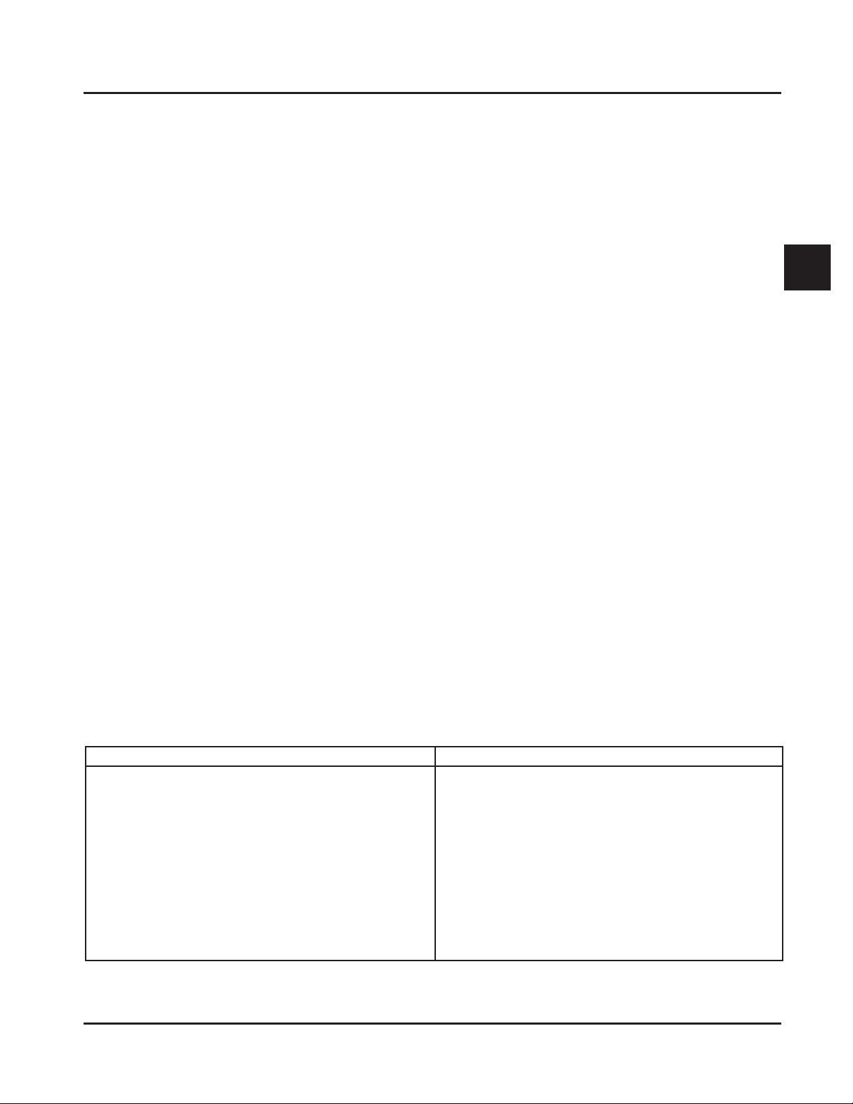
General
These engines are equipped with Kohler's heavy-duty,
cyclonic air cleaner system. See Figure 4-1. The air
cleaner includes a high-density, pleated paper main
element (see Figure 4-2), and inner safety element (see
Figure 4-3).
Figure 4-1. Heavy-duty Air Cleaner Assembly.
4
Figure 4-3. Air Cleaner Element with Inner
Element.
Air Cleaner Element Service
Every 250 hours of operation (more often under
extremely dusty or dirty conditions), replace the
paper element and cylindrical inner element. Follow
these steps:
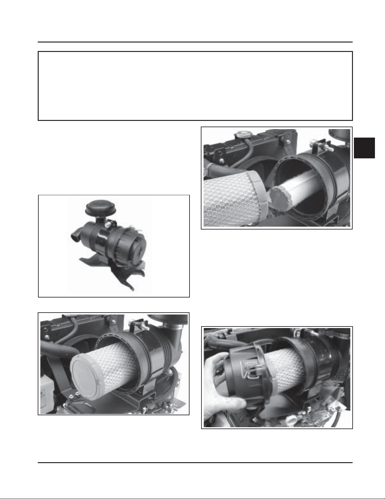
1. Unhook the two retaining clips and remove
the end cap from the air cleaner housing. See
Figure 4-4.
Figure 4-2. Air Cleaner Element.
Figure 4-4. Removing End Cap.
2. Pull the air cleaner element out of the housing.
See Figure 4-5.
4.1
Section 4
Air Cleaner and Air Intake System
Figure 4-5. Removing Air Cleaner Element.
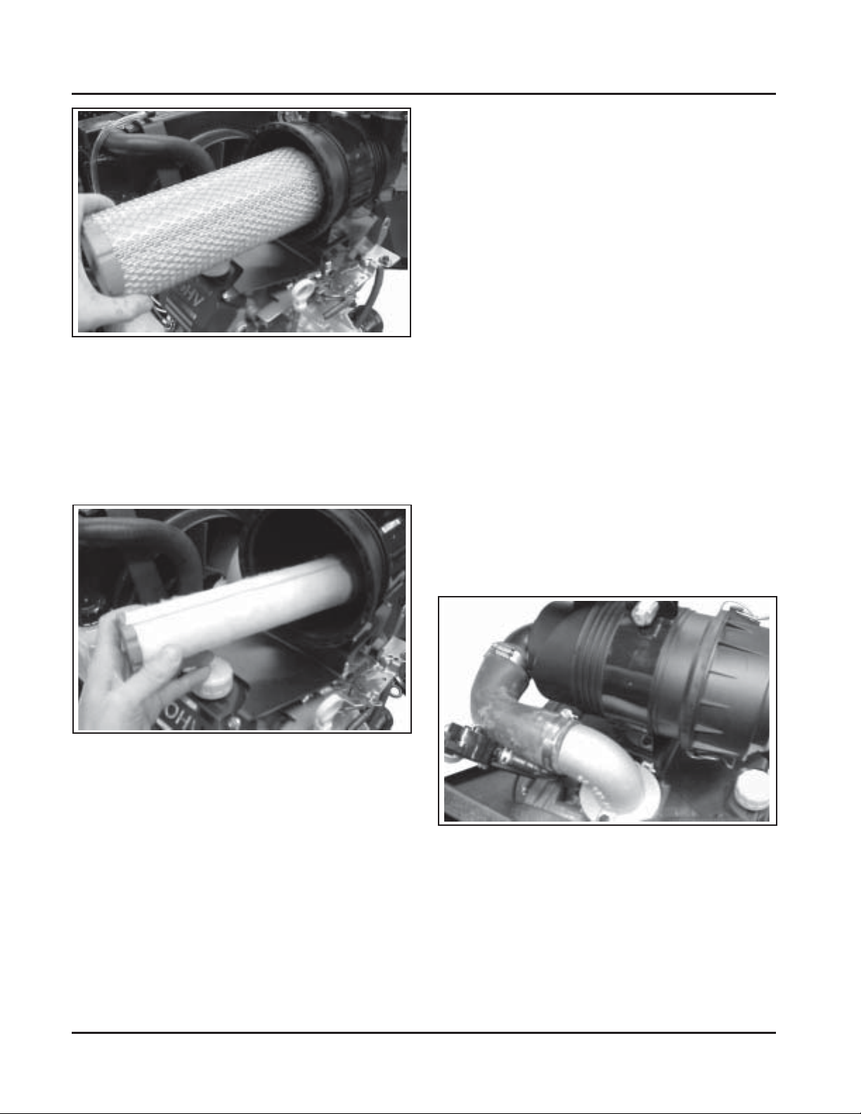
3. Check the condition of the inner safety element. It
should be replaced whenever it appears dirty,
typically every other time the main element is
replaced. Before removing it from the housing,
clean the area around the base of the inner
element, so dirt does not get into the engine. See
Figure 4-6.
6. Reinstall the end cap, so the dust ejector valve
faces down, and secure with the two retaining
clips.
Air Cleaner Components
Air Cleaner Housing/End Cap Assembly
Make sure air cleaner housing including the dust
ejector valve and the end cap is in good condition and
not cracked. The two retainer clips should positively
lock when the cap is installed.
Air Cleaner Hose
Inspect the air cleaner hose to make sure it is not
cracked, split or damaged. Check that the air cleaner
hose is securely clamped to both the air cleaner outlet
and the inlet elbow on the carburetor.
Air Cleaner Mounting Base
Make sure the base is securely fastened to the upper
valve cover screw locations and the screws securing
the clamp bracket for the air cleaner housing are
properly installed and tight.
Figure 4-6. Removing Cylindrical Inner Element.
4. The elements must be replaced when dirty. Do
not attempt to clean the elements with
pressurized air, or other means, as the elements
will be ruined. Handle new elements carefully;
do not use if the sealing surfaces are bent or
damaged. Replace any damaged or questionable
components.
5. If it is being replaced, install the new inner
element, Kohler Part No. 25 083 04-S, followed by
the canister outer element; Kohler Part No.
25 083 01-S. Slide each fully into place in the
housing.
Breather Hose
Make sure the hose is in good condition, not cracked,
and properly secured to the breather cover and
adapter fitting.
Figure 4-7. Air Cleaner Assembly .
4.2
Fuel System and Governor
Section 5
Fuel System and Governor
Section 5
Description
The Aegis horizontal twins use two different types of
fuel systems; carbureted or electronic fuel injection
(EFI).
This section covers the standard carbureted fuel
systems. The EFI systems are covered in subsection 5B.
The governor system, covered at the end of this
section, is the same for both fuel systems.
WARNING: Explosive Fuel!
Gasoline is extremely flammable and its vapors can explode
if ignited. Store gasoline only in approved containers, in
well ventilated, unoccupied buildings, away from sparks or
flames. Do not fill the fuel tank while the engine is hot or
running, since spilled fuel could ignite if it comes in contact
with hot parts or sparks from ignition. Do not start the
engine near spilled fuel. Never use gasoline as a cleaning
agent.
Fuel System Components
The typical carbureted fuel system and related
components include the following:
Fuel Recommendations
General Recommendations
Purchase gasoline in small quantities and store in
clean, approved containers. A container with a
capacity of 2 gallons or less with a pouring spout is
recommended. Such a container is easier to handle
and helps eliminate spillage during refueling.
• Do not use gasoline left over from the previous
season, to minimize gum deposits in your fuel
system and to ensure easy starting.
• Do not add oil to the gasoline.
• Do not overfill the fuel tank. Leave room for the
fuel to expand.
Fuel T y pe
For best results, use only clean, fresh, unleaded
gasoline with a pump sticker octane rating of 87 or
higher. In countries using the Research fuel rating
method, it should be 90 octane minimum.
5
• Fuel Tank
• In-line Fuel Filter
• Fuel Pump
• Carburetor
• Fuel Lines
Operation
The fuel from the tank is moved through the in-line
filter and fuel lines by the fuel pump. On engines not
equipped with a fuel pump, the fuel tank outlet is
located above the carburetor inlet, allowing gravity to
feed fuel to the carburetor.
Fuel then enters the carburetor float bowl and is
moved into the carburetor body. There, the fuel is
mixed with air. This fuel-air mixture is then burned in
the engine combustion chamber.
Unleaded gasoline is recommended as it leaves less
combustion chamber deposits and reduces harmful
exhaust emissions. Leaded gasoline is not
recommended and must not be used on EFI engines,
or on other models where exhaust emissions are
regulated.
Gasoline/Alcohol blends
Gasohol (up to 10% ethyl alcohol, 90% unleaded
gasoline by volume) is approved as a fuel for Kohler
engines. Other gasoline/alcohol blends are not
approved.
Gasoline/Ether blends
Methyl Tertiary Butyl Ether (MTBE) and unleaded
gasoline blends (up to a maximum of 15% MTBE by
volume) are approved as a fuel for Kohler engines.
Other gasoline/ether blends are not approved.
5.1

Section 5
Fuel System and Governor
Fuel Filter
Most engines are equipped with an in-line fuel filter.
Periodically inspect the filter and replace with a
genuine Kohler filter every 200 operating hours.
Troubleshooting – Fuel System Related Causes
T est Conclusion
1. Check the following:
a. Make sure the fuel tank contains clean, fresh,
proper fuel.
b. Make sure the vent in fuel tank cap is open.
c. Make sure the fuel valve is open.
d. Make sure vacuum and fuel lines to fuel
pump are secured and in good condition.
2. Check for fuel in the combustion chamber.
a. Disconnect and ground the spark plug leads.
b. Close the choke on the carburetor.
c. Crank the engine several revolutions.
d. Remove a spark plug and check for fuel at the
tip.
3. Check for fuel flow from the tank to the fuel
pump.
a. Remove the fuel line from the inlet fitting of
fuel pump.
b. Hold the line below the bottom of the tank.
Open the shut-off valve (if so equipped) and
observe flow.
Fuel System T est s
When the engine starts hard, or turns over but will not
start, it is possible that the problem is in the fuel
system. To find out if the fuel system is causing the
problem, perform the following tests.
2. If there is fuel at the tip of the spark plug, fuel is
reaching the combustion chamber.
If there is no fuel at the tip of the spark plug,
check for fuel flow from the fuel tank (Test 3).
3. If fuel does flow from the line, check for faulty
fuel pump (Test 4).
If fuel does not flow from the line, check the fuel
tank vent, fuel pickup screen, in-line filter, shutoff valve, and fuel line. Correct any observed
problem and reconnect the line.
4. Check the operation of fuel pump.
a. Remove the fuel line from the inlet fitting of
carburetor.
b. Crank the engine several times and observe
flow.
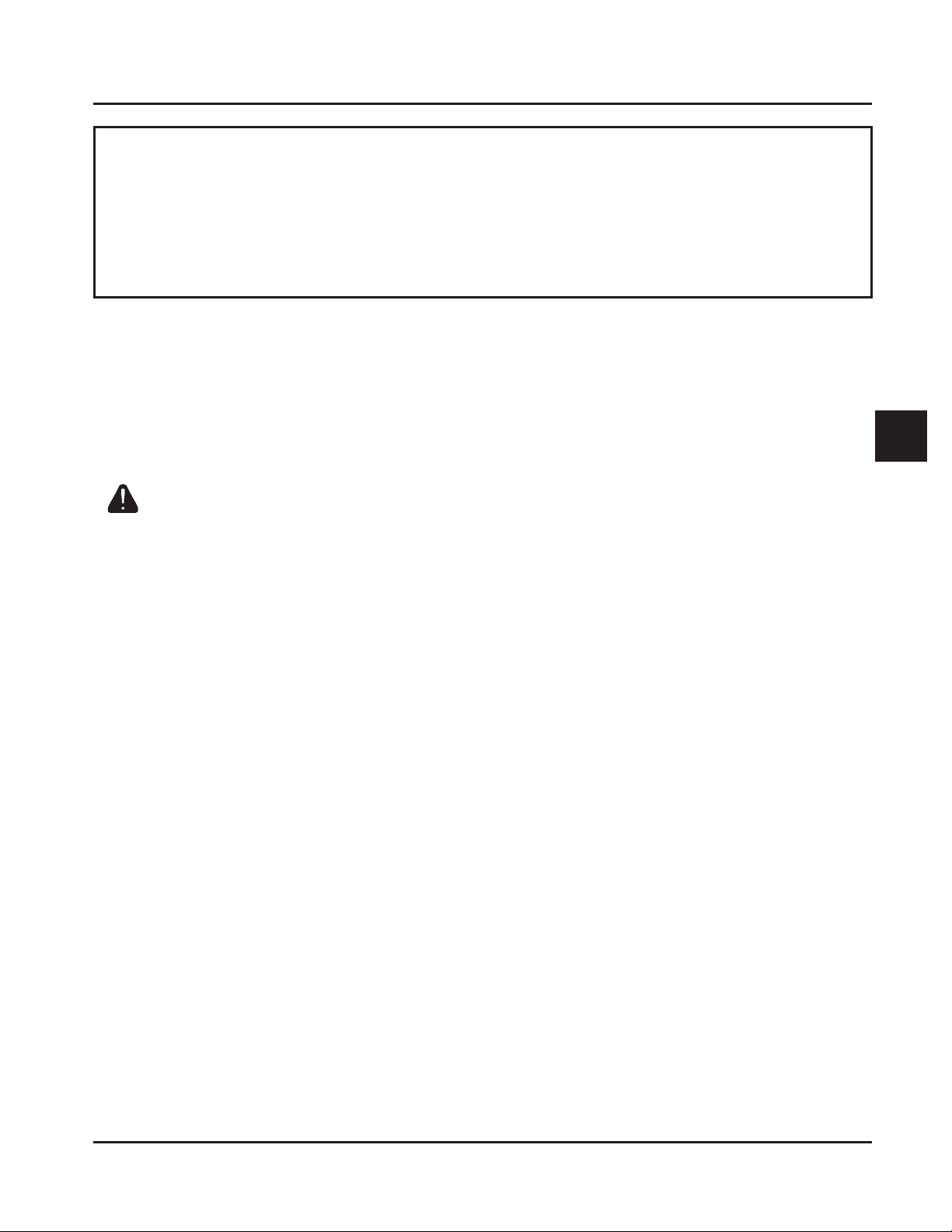
Fuel Pump
General
These engines are equipped with either a mechanical,
or pulse style fuel pump. See Figure 5-1.
4. If fuel does flow from the line, check for faulty
carburetor. (Refer to the "Carburetor" portions of
this section.)
If fuel does not flow from the line, check for a
clogged fuel line. If the fuel line is unobstructed,
check for overfilled crankcase and/or oil in pulse
line. If none of the checks reveal the cause of the
problem, replace the pump.
Operation
Pulse Fuel Pump
Operation and pumping action is created by
alternating positive and negative pressures within the
crankcase. This pressure is transmitted to the pulse
pump through a rubber hose connected between the
pump and the crankcase. The pumping action causes
the diaphragm on the inside of the pump to pull fuel
in on its own downward stroke and to push it into the
carburetor on its upward stroke. Two check valves
prevent fuel from going backward through the pump.
5.2
Section 5
Fuel System and Governor
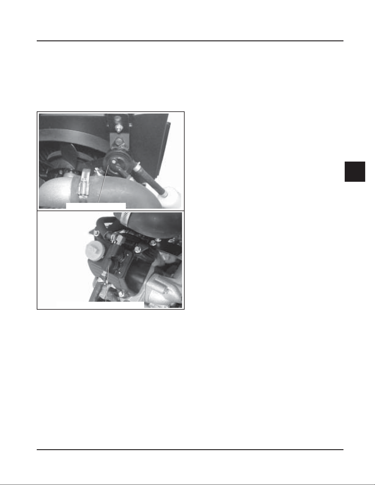
Mechanical Fuel Pump
The mechanical fuel pump is built into the #2 valve
cover. The actuating arm of the pump extends down
inside the cover and contacts one of the rocker arms.
Downward movement of the rocker arm allows the
pump diaphragm to flex down, drawing in fuel. As
the rocker arm comes up, the fuel is forced out toward
the carburetor.
Pulse Fuel Pump
3. Remove the vacuum line that connects the pump
to the crankcase.
4. Install a new pump using the hex flange screws.
NOTE: Make sure the orientation of the new
pump is consistent with the removed
pump. Internal damage may occur if
installed incorrectly.
5. Connect vacuum line between the pump and
crankcase.
6. Tighten the hex flange screws to 2.3 N·m
(20 in. lb.).
7. Connect the fuel lines to the inlet and outlet
fittings.
Mechanical Fuel Pump
1. Disconnect the fuel lines from the inlet and outlet
fittings.
2. Clean the area and remove the four screws
securing the valve cover/pump assembly to the
cylinder head. Loosen (but do not remove) the
four valve cover screws on the opposite side.
5
Mechanical Fuel Pump
Figure 5-1. Fuel Pump Styles.
Replacing The Fuel Pump
Replacement pumps are available through your source
of supply. To replace the pulse pump follow these
steps. Note the orientation of pump before removing.
Pulse Fuel Pump
1. Disconnect the fuel lines from the inlet and outlet
fittings.
2. Remove the hex flange screws mounting fuel
pump to support.
3. Lift the air cleaner mounting bracket up slightly
and remove the valve cover/pump assembly.
Remove and discard the old gasket.
4. Rotate the engine by hand while observing the
actuating rocker arm. Stop rotating when end of
the rocker arm is at the lowest point (spring is at
maximum compression, and valve is open).
5. Position the new gasket onto the new cover/fuel
pump assembly and install onto cylinder head.
Align the air cleaner mounting bracket holes with
the upper two valve cover screw holes.
6. Install the longer screws in the upper holes
and the shorter screws in the lower holes.
Finger tighten all eight valve cover mounting
screws (four each side), then torque the screws
to 6.2 N·m (55 in. lb.) in the sequence shown in
Figure 5-2.
5.3
 Loading...