

Page 1

IN-WALL TANK
K-6283K/ K-6286K/K-6286RK-6284K/
·
·
·
·
Read installation guide in illustration and word file
carefully, and install the tank according to
instructions in the guide to avoid product damage
and installation inconvenience caused by
inappropriate operation.
All data contained is based upon the last product
information available at the time of publication.
Kohler Co. Reserves the right to implement changes
of product characteristics, packaging and availability
at any time without further notice.
Do not apply erosive cleanser and solvent in the
tank, which will damage tank spares and result in
leakage in the tank. Kohler will not be responsible
for any damage related to above mentioned
cleanser or solvent.
Do not apply spares that are not provided by Kohler,
and please note that glass adhesive tape shall not
be applied to the installation of Kohler spares.
Kohler will not be responsible for any damage
related to installation with spares not provided by
Kohler.
Ordering Information
ODEON Tank Cover......................................K-6283K-**
(With Iron Rack For Wall-Hung
Toilet)
ODEON In-Wall Tank (Without Iron Rack For Wall-Hung
Toilet).....................................K-6286K-NA/K-6286R-NA
ODEON In-Wall Tank
................................................K-6284k-NA
Function Explanation
·
·
·
·
·
Anti flow-backwards
Adjustment of inlet water level
Adjustment of flushing volume
Single/double gear
Adjustable toilet height
flushing
Design And Installation Concept Of In-wall
Tank
·
·
Installation of in-wall tank is much easier and nicelooking comparative to that of traditional tank.
Meanwhile, the space layout will be more
reasonable due to the application of in-wall tank
pipes and connectors.
The most remarkable advantage of in-wall tank is
that the installation will never be limited to certain area,
and can be installed wherever as you wish, which will
make the bathroom layout more reasonable and nicelooking, and make good use of every inch of the
bathroom space.
Advantages Of In-wall Tank
·
·
·
·
·
·
·
·
Anti-strike and erosion proof tank of macromolecule
materials, and leak proof.
Advanced tank spares, adjustable to of 3/6
liters, with single/double gear technology.
Sustainable to pressure of 400 kgs.
Impact free to wall structures, and excellent sound
insulation effect.
Easy installation and time efficient.
No requirements of other installation spares.
Easy maintenance and no necessity of removing the
wall in the process of maintenance.
Clean, garbage free, and space-saving efficient.
flushing
INSTALLATION
INSTRUCTIONS
-1-
1048671-K01-B
Copyright 2006 Kohler Co.
C
ODEON
Page 2
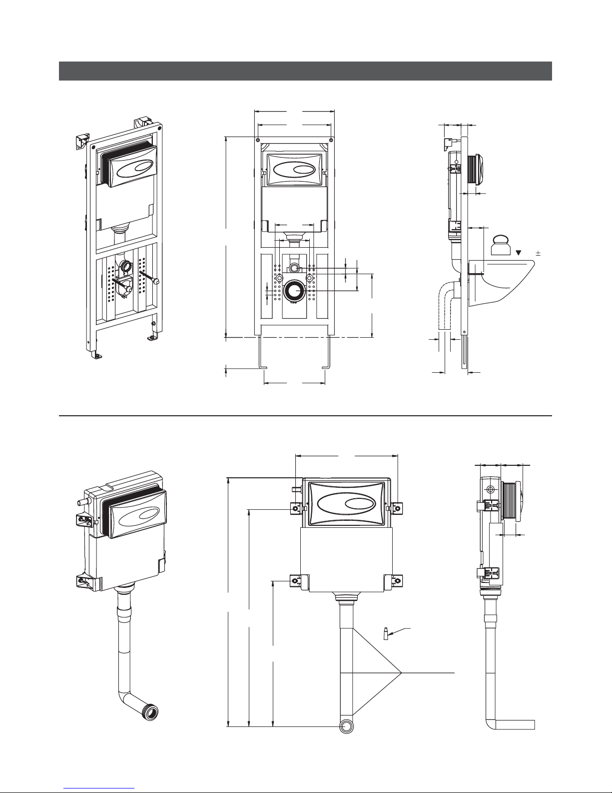
ROUGHING-IN
UNIT: mm
Installation dimensions with iron rack K-6284K
-2-
1048671-K01-B
Installation dimensions without iron rack for wall hung K-6286K/K-6286R
UNIT: mm
Adhesive
Adhesive
Agglutination
1275
1150
850
438
95
100
15-55
478
438
0-200
1190
300
25
135
35
180
230
365
OK
FFB
100-155
15-55
0-140
400kg
40
400 10
95-135
90
Page 3
INSTALLATION
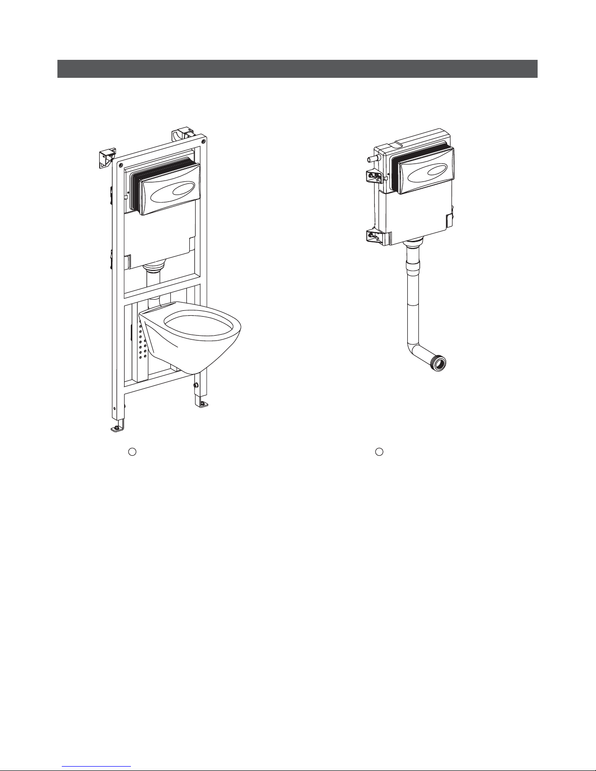
Ways of Installation
In-wall Tank With Iron Rack For
Wall-Hung Toilet
-3-
1048671-K01-B
In-wall Tank Without Iron Rack
For Wall-Hung Toilet
K-6286K-NA/K-6286R-NA
1 2
K-6284K-NA
Page 4
-4-
1048671-K01-B
Installation
1. Install the fixing cap in the holes of fixing frame, then
tighten the hexagonal screws on the fixing frame with
medium allen key as shown in illustration A.
Tighten the bolts with medium allen key as shown in
illustration B, and adjust the height of the adjustable
bracket according to customer's requirements.
Fixing Frame
Fixing Cap
Hexagonal Screw
Tank Frame
Nut
Adjustable Bracket
Medium Allen Key
AB
2. Drill four holes with diameter of 12mm and depth of
60mm with churn drilling as shown, and fill in the
holes with bulge screw and tighten the long screw.
Bulge Screw
Long
Screw
Gasket
Bulge Screw
Long Screw
A. Installation Procedures For In-wall Tank With Iron Rack
Nut
Page 5

-5-
1048671-K01-B
3. Tighten the hexagonal long screw with medium allen
key as shown in illustration A.
Tighten the screw of adjustable brackets with
medium allen key as shown in illustration B, and
tighten the long screw with spanner.
Ensure the tank to remain level.
Level
Hexagonal screw
Screw
Medium Allen Key
Adjustable Bracket
Spanner
Long
Screw
Loosen
Tighten
AB
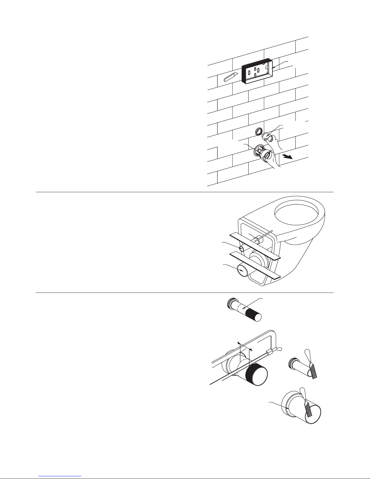
4. Fix the drainage cap on the fixing bracket as shown
in the illustration. Tighten the screws with medium
allen key and install the drainage cap on the
drainage hole.
Drainage
Hole
Fixing Bracket
Drainage Cap
Screw
Medium Allen Key
Page 6
-6-
1048671-K01-B
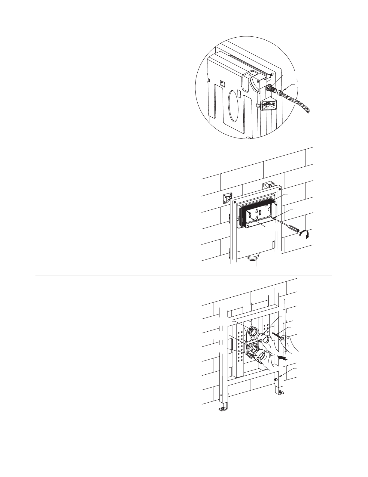
5. Install the water pipe to the connecting pipe at the
side of the tank for water supply. ()Inlet valves
should be shut down
6. Install the rectangular shield in the block screen of
the tank, and tighten the screw to fix the rectangular
shield to the tank.
Rectangular
Shield
Screw
Block
Screen
7. Tighten the long screw into the holes of tank bracket,
and cover the drainage cap with big filtration cap,
and the drainage hole with small filtration cap.
Connecting
Pipe
Water Pipe
Drainage Hole
Drainage Cap
Big Filtration Cap
Small Filtration Cap
Long Screw
Tank Bracket
Page 7
-7-
1048671-K01-B
8. When finishing the brickwork of the wall, take out the
big and small filtration caps, and eliminate unwanted
rectangular shield with a sharp knife.
9. Install the inlet pipe and outlet pipe to the toilet as
shown, and mark on the pipes at the back side of the
tank with a ruler and a pencil, and reserve
appropriate space according to the distance from the
back of the tank to the outlet hole on the wall.
Rectangular Shield
Big Filtration Cap
Small Filtration Cap
Inlet Pipe
Outlet ipeP
10. Eliminate unwanted part of the pipe and outlet
pipe according to the marks of reserved space, and
rasp a smooth surface with files.
inlet
Inlet Pipe
Reserved
Space
Outlet ipeP
Page 8
-8-
1048671-K01-B
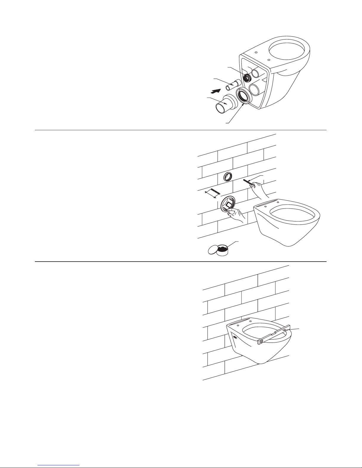
11. Install the big and small leak-proof gaskets on inlet
pipe and outlet pipe, then install it to corresponding
pipes on the toilet tank.
Small Leak-proof Gasket
Inlet Pipe
Outlet ipeP
Big Leak-proof Gasket
12. 48mm-58mm of the long screw shall be reserved
outside the wall as shown in the illustration. If the
long screw outside the wall is not long enough or
much longer than that needed, it should be adjusted
with screwdriver or by hand. Then apply lubricant to
drainage pipe and limber pipe to ensure a smooth
installation.
Long Screw
Lubricant
48mm-58mm
13. Install the toilet as shown in the illustration, and use
a spirit level to ensure the toilet to remain level.
Spirit Level
Page 9

-9-
1048671-K01-B
14. Install the rubber cover gasket, hexagonal nut and
decoration cap onto long screw according to the
order shown in the illustration.
Screw Cover
Rubber Cover
Hexagonal Nut
Decoration Cap
Gasket
Long Screw
15. When fixing the adjustable board to block screen,
the locknut should be put directly on positing of the
sign of OPEN . Remark: Stir pole shall remain
level.
Block Screen
Locknut
Adjustable Board
Stir Pole
Page 10

1048671-K01-B
16. Fix the adjustable board on the wall by tightening
the locknut as shown in the illustration. And the
locknut should be directly put on the position of the
sign of LOCK . (Indications are marked on the
adjustable board, please refer to indications in
installation)
17. Install the cover as shown in the illustration. Put the
lock on the cover directly on the reversed lock on
adjustable board, then push the cover and lock it.
The installation shall begin from bottom to top.
Lock
Adjustable Board
Reversed Lock
Cover
Adjustable Board
Locknut
-10-
Page 11

18. In-wall tank toilet is ready to be put into use.
Long Flush
Button
Short Flush
Button
-11-
Finished Installation Illustration
1048671-K01-B
1. Mark on the wall for appropriate position for fixing
bracket, and drill four holes with diameter of 12mm
and depth of 60mm with churn drilling as shown in
illustration, and fill in the holes with bulge screw and
tighten the long screw to set the fixing bracket.
Note: Ensure the fixing bracket to remain level.
Bulge Screw
Long Screw
Fixing Bracket
B. Installation Procedures For In-wall Tank Without Iron Rack For Wall-Hung Toilet
Page 12

2. Install the fixing bracket first, then put the tank on the
fixing bracket, and fix the fixing frame in the slot of
the tank, and tighten the screws. Lock the fixing slot
to corresponding position on fixing frame.
Fixing Frame
Fixing Slot
Long Screw
Fixing Bracket
Tank
-12-
1048671-K01-B
3. Install the rectangular shield in the block screen of
the tank, and tighten the screw to fix the rectangular
shield to the tank.
4. Fix the leak-proof gasket to syphon as shown in
illustration, and adjust the syphon to appropriate
position to be fixed to the wall-hung toilet.
Rectangular Shield
Screw
Leak-proof Gasket
Syphon
Page 13

5. When finishing the brickwork, eliminate unwanted
part of the rectangular shield.
Sharp Knife
Rectangular Shield
-13-
1048671-K01-B
7. Fix the adjustable board on the wall by tightening the
locknut as shown in the illustration. And the locknut
should be directly put on the position of the sign of
LOCK . (Signs are marked on the adjustable
board, please refer to the indications in installation)
6. When fixing the adjustable board to block shield, the
locknut should be put directly on positong of the sign
of OPEN .
Remark: Stir pole shall remain level.
Adjustable Board
Locknut
Stir Pole
Block
Shield
Locknut
Adjustable Board
Page 14

Lock
Adjustable Board
Reversed Lock
Cover
8. Install the cover as shown in the illustration. Put the
lock on the cover directly on the reversed lock on
adjustable board, then push the cover and lock it.
The installation shall begin from bottom to top.
-14-
1048671-K01-B
9. In-wall tank toilet is ready to be put into use.
Long Flush
Button
Short Flush
Button
Finished Installation Illustration
Page 15

A. Hold the cover with both hands and push upward to
take down the cover.
MAINTENANCE AND CONTROL PROCEDURES
Cover
Cover
B. Tighten the locknut to the marked position of
OPEN to take out the adjustable board.
Locknut
C. Pin the indentation on block screen with screwdriver
to take out the block screen.
Block
Screen
-15-
1048671-K01-B
Page 16

D. Wash Filtration Net
Close corner valve first, then loosen and take out the
tighten nut, and wash the waste on filtration net with
clean water. Then reset the tighten nut to the original
position.
Open
Close
Corner Valve
Tighten Nut
Filtration Net
Loosen Nut
E. Adjust The Control Pole Of Drainage Valve
Pin the pole first to take out the control button as
shown in the illustration. Then take out the fixing
frame with both hands.
Pole
Control Button
Fixing Frame
Fixing Frame
-16-
1048671-K01-B
Page 17

F. Pull out reversed lock on the fixing frame as shown
in the illustration, and adjust the height of the control
poles to ensure the leak-proof of drainage valve.
Fixing Frame
Reversed
Lock
Control
Pole
G. Adjust Drainage Valve
Drainage volume and overflow level of the tank can
be adjusted by drainage valve: 1) Heavy drainage
adjustment: Open adjustment switch to open the
small hole. 2) Slight drainage adjustment: adjust the
height of floating box and the water level of slight
drainage will be at the bottom of the floating box.
Control Pole
Drainage Valve
Adjustment Switch
Floating Box
-17-
1048671-K01-B
Page 18

H. Adjust Inlet Valve
Hoist and reduce the water level in the tank by
adjusting the control pole. Turn the control pole
counterclockwise to lower down the floating box and
reduce the water level of the tank. Turn the control
pole clockwise to hoist the floating box and increase
the water level in the tank.
Control Pole
Floating Box
TROUBLE SHOOTING PROCEDURESTROUBLE SHOOTING PROCEDURES
No water fills in via inlet
valve
The inlet valve is closed Open inlet valve (refer to page 15)
Floating box of inlet valve is blocked by tank wall Adjust floating box to appropriate position
Floating box of inlet valve is block by waste Wash the floating box with clean water
Wrong installation of adjustable board Reset (refer to page 9)
Control pole is too long
Adjust the control pole to appropriate
position
Water level of the inlet valve is not appropriate
No drainage when
pressing the heavy and
slight drainage button
Too high or too low
water level
Leak of the toilet and
squat
Symptoms
Probable Causes
Recommended Action
Control pole is too short
Inappropriate adjustment of the overflow pipe
Toilet swing
Hexagonal nut is loose
Readjust water level (refer to page 16)
Adjust the control pole to appropriate
position
Adjust the overflow pipe to appropriate
position
Tighten the hexagonal nut (refer to page 9)
Kohler plumbing fixtures and fittings are warranted to
be free of manufacturing defects.
To obtain warranty service, contact Kohler either
through your Dealer or Plumbing Contractor or by
writing Kohler Co., Attn: Consumer Affairs Department,
Kohler, WI 53044 U.S.A.
Some states do not allow limitations on how long an
implied warranty lasts or the exclusion or limitation of
incidental or consequential damages, so this limitation
and exclusion may not apply to you. This warranty
gives you specific legal rights. You may also have rights
which vary from state to state.
This is our exclusive written warranty.
Kohler Co., Kohler, Wisconsin 53044
Kohler Co. will, at its election repair, replace, or make
appropriate adjustment where Kohler Co. inspection
discloses any such defects occurring in normal usage
within one year after installation.
Co.
Kohler Co. is not
responsible for installation costs.
Implied warranties, including that of
merchantability and fitness for a particular purpose,
are expressly limited in duration to the duration of
this warranty. To the extent permitted by law,
Kohler Co. disclaims all implied warranties
including merchantability and fitness for a
particular purpose. Kohler Co. disclaims any
liability for special, incidental, or consequential
damages.
LIMITED ONE-YEAR WARRANTYLIMITED ONE-YEAR WARRANTY
-18-
1048671-K01-B
Page 19

IN-WALL TANK
SERVICE PARTS PAGE
K-6283K/K-6284K
-19-
Expanding Bolt Cap
Fixation Base
Screw Base
Self-tapping Screw
Frame Screw
Screw Cap
Mechanical kit for pipe connection
Screw M5 x 20
Fixation Frame
Screw M12 x 40
Installation Frame
Mechanical kit for Fixation with Floor
Washer, 10 2
Screw M10 x 30
Bracket Nut
Bracket
Washer, 19 8 3
Assembling kit for wall-Hung bowl
Screw, M12 x 179
Screw Cover
Rubber Washer
Screw, M12 x 10
Washer
Screw Cover
Straight Outlet Pipe System
Outlet Pipe, Rear
Rubber Gasket
Outlet Pipe, Front
Outlet Pipe
Rubber Gasket
Plug, Big
Assembling Kit Tank with Wall
INSTALLATION
INSTRUCTIONS
1048671-K01-B
ODEON
Cap
Rubber Gasket
Curve Pipe
Straight Pipe
Rubber Gasket
Interior Hexagon Wrench
Optional Parts
Page 20

-20-
KI07 1045103 Takeup Mechanical
1045104 Takeup
1045105 Swith Arm, Left, Rear
1047622 Swith Arm, Left, Front
1047623 Swith Arm, Right, Rear
1047624 Swith Arm, Right, Front
1045106 Location Pin
1045107 Bracket
1047626 Hook
1045108 Hook, Left
1045109 Hook, Right
Roof Panel
1045111 Drive Mechanical
1045112 Takeup
1045113 Push Bar
1045114 Spring
1045115 Fix Bar
1045116 Clip Ring
Square Mask
Foam Piece
Screw ST 35
4
Cover Assembly Kit
Right Location Block
Spring
Right Location Shank
Left location block
Left Location Shank
Fixation Shank
Location Panel
628 -*
In-wall Tank Cover
3K
Cover
Stainless Steel
Push Button Spring
Fixation Cover
Big Push Button
Small Push Button
IN-WALL TANK
SERVICE PARTS PAGE
K-6283K/K-6284K
INSTALLATION
INSTRUCTIONS
1048671-K01-B
Screw ST 38
ODEON
Page 21

Tank Mount Kit
Wrap
-21-
Bracket
T Shape Pint
Straight Pin
Washer 10 2
Self-screw 7 x 83.6
Bracket, Left
Bracket, Right
Panel Lock Kit
Tank Outlet Pipe
747UKB Side Fill Valve
Flush Valve Assembly
P51 Flush Valve
G12 Filter/G12
G06 Valve/G06
Tank Inlet Connection
Washer
Locknut
Screw
Lock Sheath
Connection Pipe
O-Ring
Adjustment Pipe
Rubber Gasket
Outlet Pipe
Rubber Gasket
Plug, Small
Inlet hose
Bracket
Bracket A
Joint Nut
Hook
Foam Rubber
Joint Nut
Rubber Gasket
Plastic Tank
Fill Valve Assembly
IN-WALL TANK
SERVICE PARTS PAGE
K-6283K/K-6284K
INSTALLATION
INSTRUCTIONS
1048671-K01-B
ODEON
Page 22

IN-WALL TANK
SERVICE PARTS PAGE
K-6286K/K-6286R
INSTALLATION
INSTRUCTIONS
ODEON
-22-
1048671-K01-B
Cap
Rubber Gasket
Curve Pipe
Straight Pipe
Rubber Gasket
Optional Parts
Page 23

IN-WALL TANK
SERVICE PARTS PAGE
K-6286K/K-6286R
INSTALLATION
INSTRUCTIONS
ODEON
-23-
1048671-K01-B
KI07 1045103 Takeup Mechanical
Page 24

IN-WALL TANK
SERVICE PARTS PAGE
K-6286K/K-6286R
INSTALLATION
INSTRUCTIONS
ODEON
-24-
1048671-K01-B
 Loading...