

Page 1
INTRODUCTION
This service instruction will help you understand the opera
tion and repair of Kohler low profile onepiece toilets.
The following models are included in these instructions:
K-3378-EB PILLOW TALK K-3383-EB PALARRE
K-3385-EB ROCHELLE K-3397-EB SAN RAPHAEL
K-3402-EB RIALTO K-3408-EB CABERNET
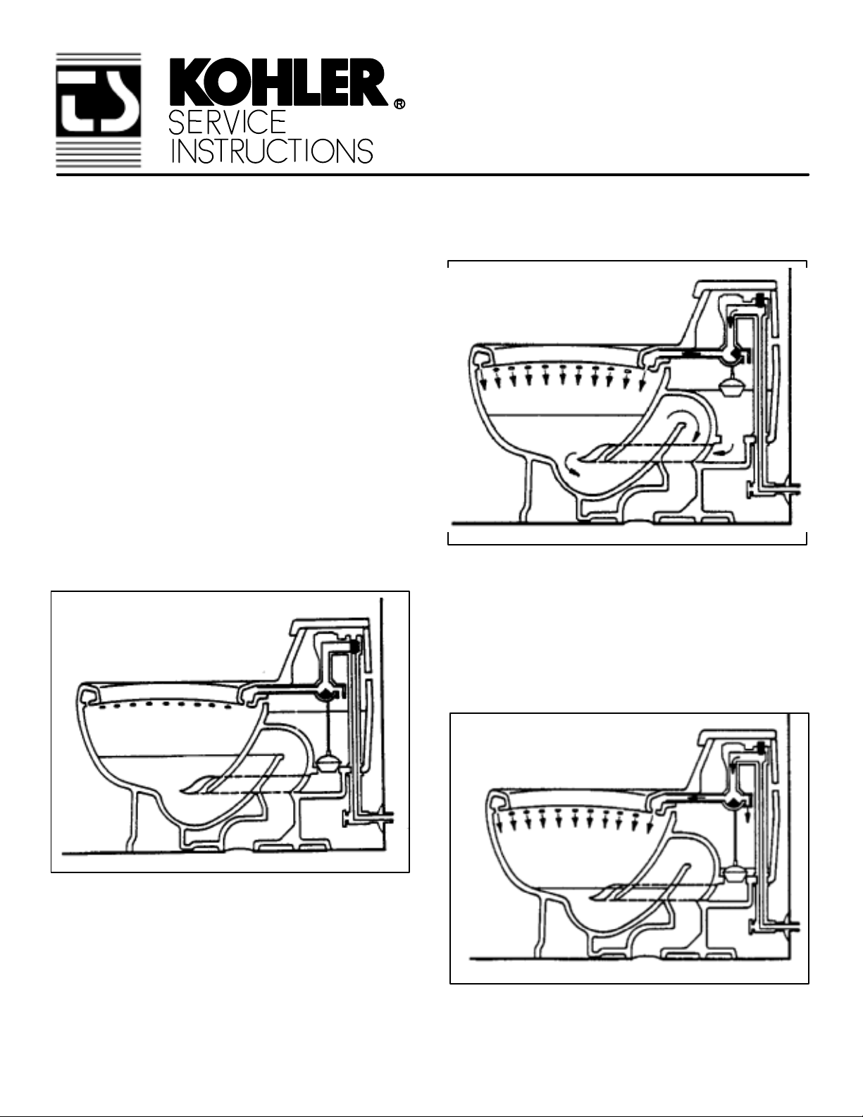
THEORY OF OPERATION
Consider how a low profile, onepiece toilet differs from the
closecoupled toilet. All the water in a close coupled toilet is
held in a tank that is above the rim of the bowl. Water to the
rim and jet is supplied by gravity.
SIPHON VORTEX LOW
PROFILE ONE-PIECE
TOILETS
On the other hand, a onepiece toilet holds all the tank
water below the rim of the bowl as shown in Fig. #1.
Fig. #1
When the trip lever is actuated, water enters the supply
valve and flows to the diverter valve. At this point all line
water is diverted to the rim. The tank water is only used to
start the water action in the bowl, and to direct water to the
upleg of the trapway to start the siphonic action as illus
trated in Fig. #2.
Fig. #2
After the flush is completed, the diverter valve directs water
to the rim for bowl refill, and to the tank for tank refill.
Since water which only will be directed to the jet is stored in
the tank, sufficient water to the rim must be supplied by the
supply valve as shown in Fig. #3.
Fig. #3
106423-0290
Page 2
OF OUTLET
I.P.S. SUPPLY
I.P.S. SUPPLY
K-3378-EB Pillow Talk
Fig. #4
OF OUTLET
K-3383-EB Palarre
Fig. #5
I.P.S. SUPPLY
K-3397-EB San Raphael
Fig. #7
OF OUTLET
K-3402-PB Rialto
Fig. #8
I.P.S.
SUPPLY
OF OUTLET
K-3385-EB Rochelle
Fig. #6
I.P.S. SUPPLY
K-3408-EB Cabernet
Fig. #9
- 2 -
Page 3
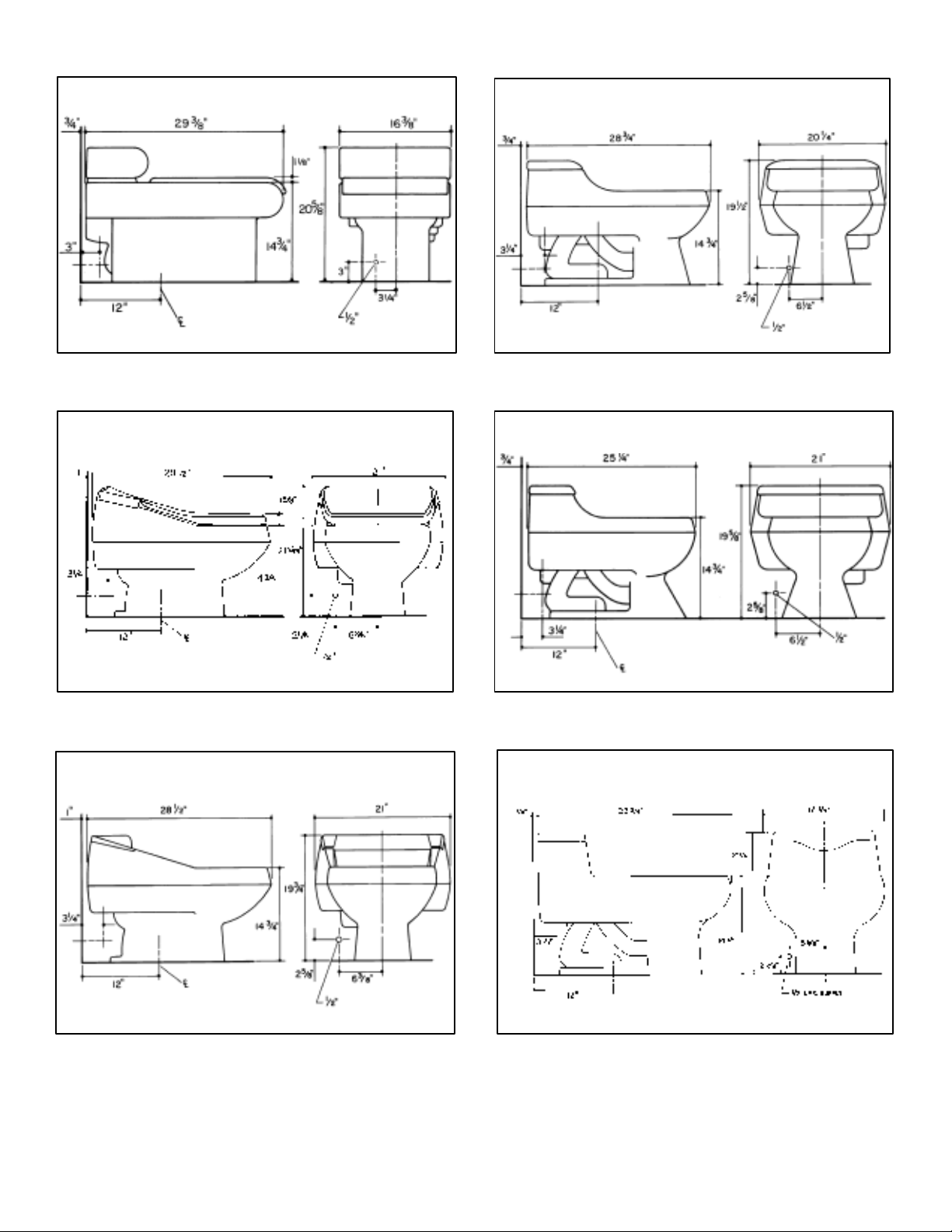
ROUGHINGIN AND INSTALLATION
CONSIDERATIONS
Kohler low profile, onepiece toilets are perfect for remodel
ing and new installations. Refer to the roughingin draw
ings Figs. #4 - #9.
Always refer to your local codes and the installation in
structions packed with the toilet.
KOHLER LOW PROFILE ONEPIECE TOILET
FEATURES
Onepiece design offers contemporary styling.
Elongated bowl offers a large water area for efficient
waste removal.
Nonoverflow design prevents the bowl from overflowing
if the toilet becomes clogged.
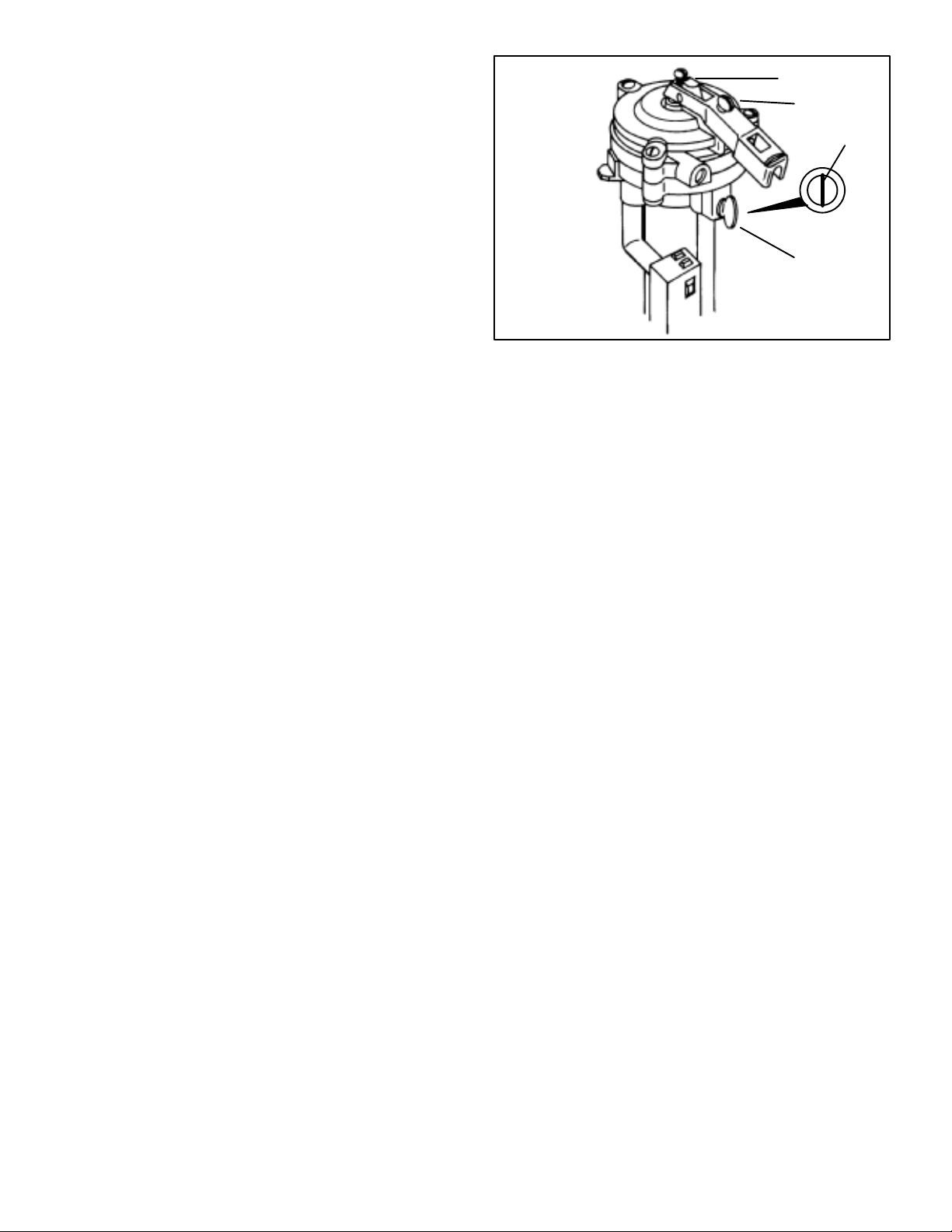
Adjusting the Float Valve
Fig. #10
Tank Water Level
Screw
Timing Screw
Slotted screw on
newer models
Seal Screw
Rialto, San Raphael, Cabernet, and Pillow Talk toilets
flush with 3.5 gallons of water for greater economy.
TwistLock flush valves on new Rialto, San Raphael,
Cabernet, and Pillow Talk toilets offer ease of replace
ment with no tools.
Siphon vortex action provides excellent flush and quiet
operation.
Large water area in bowl aids in effective waste removal.
STARTUP AND OPERATION FOR RIALTO,
SAN RAPHAEL, CABERNET, AND PILLOW
TALK TOILETS
For most satisfactory operation of this toilet, 25 to 90 psi
working pressure is required at the fixture. A full 1/2" sup
ply stop (K-7653) is recommended. A plastic nut is pro
vided with the toilet and must be used to make the supply
connection to the toilet.
1. Water Level Adjustment: Refer to Fig. #10. Turn on
the water supply to the toilet and adjust the water level
in the tank to the Water Line mark on flush valve. To
raise the water level, turn the tank water level on float
valve counterclockwise. To lower the water level, turn
the screw clockwise.
below seal height, turn the seal screw clockwise,
reflush the toilet and recheck the water level. Continue
adjustment until water stops entering the bowl just as
the seal height is reached.
If water continues to flow (in bowl) after water level
reaches seal height, turn seal screw counterclockwise
and reflush toilet. Continue adjustment until water
stops entering the bowl just as the seal height is
reached.
3. High Water Pressure Timing: Note: If toilet is installed
in an area with high water pressure (above 50 psi work
ing pressure), the float valve should be timed. To time
the float valve hold the float rod and flush the toilet. After
the toilet has completed the flush, time the refill from re
lease of rod to valve shut-off.
For K-3397-EB San Raphael, K-3378-EB Pillow
Talk, and K-3408-EB Cabernet. If the time is longer than
34 seconds, no adjustment is required. If time is under 34
seconds, turn timing screw clockwise and recheck timing.
Adjust timing screw until time is between 34 and 36 sec
onds. After timing the valve, recheck the bowl water level as
in step #2, to ensure that seal is maintained.
2. Bowl Water Level Adjustment: Use the trip chain to lift
the flush ball in the tank slightly, to allow water to trickle
into the bowl until the water level in the bowl stops ris
ing. This is the "seal height" and should be noted for
subsequent adjustment. Flush the toilet and observe
the water level in the bowl after refill. If the water level is
For K-3402-PB Rialto. If the time is longer than 26 sec
onds, no adjustment is required. If time is under 26 sec
onds, turn timing screw clockwise and recheck timing. Ad
just timing screw until time is between 26 and 28 seconds.
After timing the valve, recheck the bowl water level as in
step #2, to ensure that seal is maintained.
- 3 -
Page 4
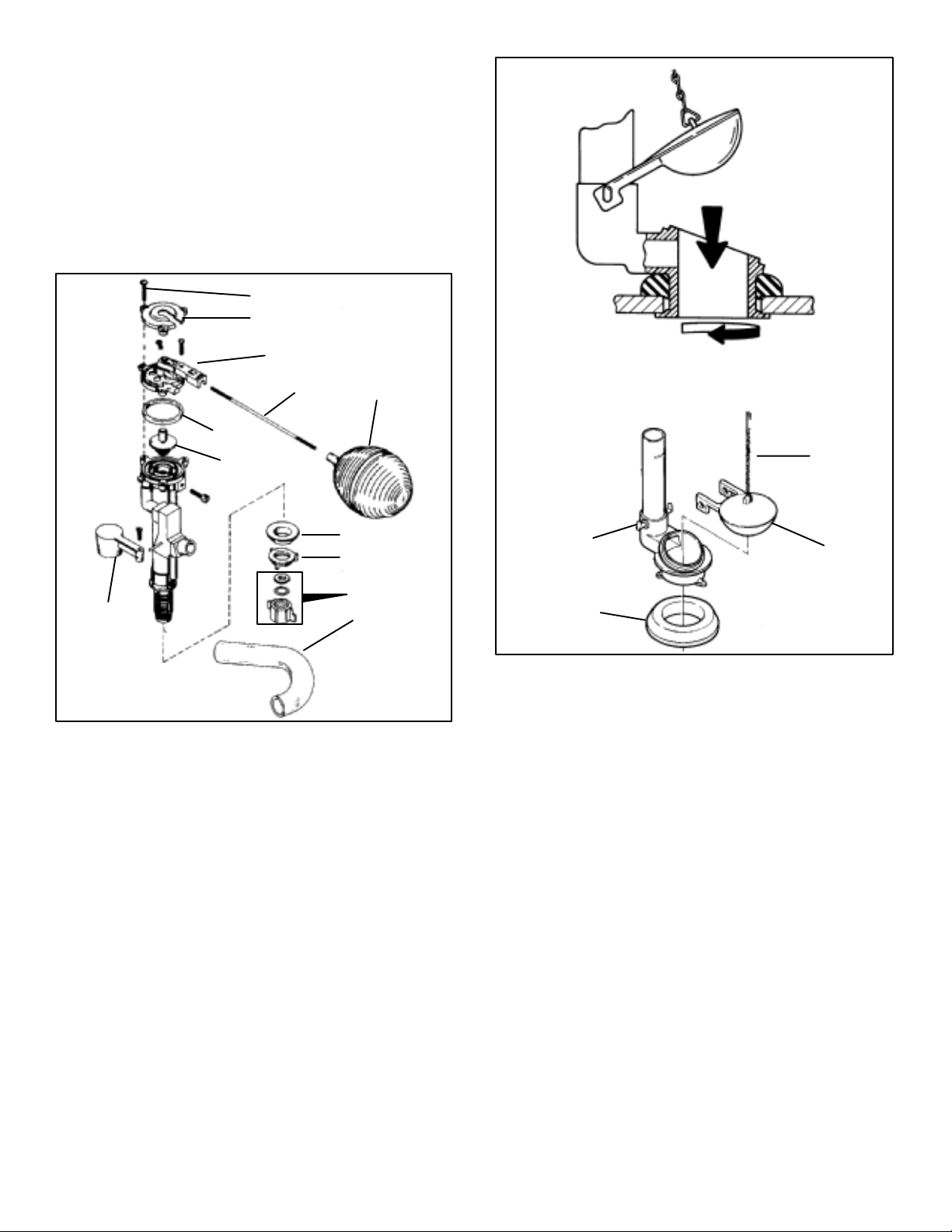
HOW TO REPAIR THE RIALTO, SAN RAPHAEL,
CABERNET, AND PILLOW TALK FLOAT AND
FLUSH VALVE.
INTRODUCTION
The following instructions are used to replace the plunger
assembly on the flush valve for the San Raphael, Rialto,
Cabernet, and Pillow Talk toilets. Refer to Fig.
#11.
Screws
Cap Top
Cap
Rim Diverter
Float
Float Rod
O-ring
Plunger Ass'y
Float Ball
Gasket
Nut
Supply Hardware
Rim Tube
Float Valve Assembly
Fig. #11
1. Loosen the screws and remove the cap top and cap.
2. Replace the Oring and plunger assembly.
3. Place the cap and cap top back on valve. Tighten with
screws.
Trip Chain
Flapper Hooks
Gasket
Flush Ball
Twist Lock Flush Valve
Fig. #12
REPLACING THE OLD STYLE FLUSH VALVE
(RIALTO AND SAN RAPHAEL ONLY)
1. Refer to Fig. #13. Loosen three screws and turn
mounting hooks inward. Remove flush valve.
2. Assemble gasket to new flush valve. Position new flush
valve with three screws and mounting hooks into hole
in tank. Make sure mounting hooks are turned inward.
Turn mounting hooks outward and tighten screws.
NOTE: TOILETS WITH OLD STYLE FLUSH VALVES CAN
NOT BE FITTED WITH THE NEW TWISTLOCK VALVE.
REPLACING THE TWIST-LOCK FLUSH VALVE
1. Refer to Fig. #12. Turn valve counterclockwise and re
move.
2. To install new valve, apply a bead of silicone to the base
of the gasket. Insert into hole inside tank. Press down
and turn clockwise until valve is in proper position.
STARTUP AND OPERATION FOR ROCHELLE
& PALARRE TOILETS
The trip lever assembly actuates the rotor and flush ball to
begin flush.
The float valve assembly controls the flow of water through
the rotor to the rim holes and tank. The adjusting screw
- 4 -
Page 5

Cap Assembly
Plunger S.A.
Seat
O-ring
Rubber Gasket
Adjusting Screw
Float Rod
Float Ball
Rotor
Lift Chain
Trip Chain
Flapper Hooks
Flush Ball
Screws
Mounting Hooks
Old Style Flush Valve
Fig. #13
controls flow at various water pressures. An antisiphon
valve prevents backflow.
For most satisfactory operation of this toilet, 25 to 80 psi
working pressure is required at the fixture. A full 1/2" sup
ply stop (K-7653) is recommended. A pressure regula
tor is recommend when pressure exceeds 125 psi.
The flush valve controls the flow of water from tank to bowl.
The flush ball and lift wire control valve operation at the end
of the flush. The lift wire provides for the accurate seating of
the flush ball.
BEFORE YOU BEGIN ADJUSTMENTS:
Refer to exploded view illustration (Fig. #14) and Fig.
#15. Make sure you understand the following before
you refer to the Troubleshooting Chart.
Screw
Rotor Arm
Lift Wire
Plastic Collar
Flush Ball
Rubber Seat Gasket
Seat Clamp
Hush
Tube
Rim
Flush
Tube
Gasket
Locknut
Supply Connection
Rochelle/Palarre Tank Fitting
Fig. #14
Trip Lever Assembly
Volume Control
Float Rod
Rotor
Rim Flush
Tube
Directional
Valve
Flush Valve
Lift Wire
Trip Lever Tank Fitting Assembly
Fig. #15
WATER LEVEL. The water level must be at the waterline
indicated at the back of the tank for proper flushing of
bowl. Bend float rod if necessary to obtain the proper
water level. The flush valve will not shut off if the water is
above the overflow. If any pressure variation occurs in
the supply line, adjust the water level when the water
pressure is at its highest point.
- 5 -
Page 6

VOLUME CONTROL. If necessary, you can adjust the
flow of water with adjusting screw. Decrease the flow by
turning the screw downward or increase the flow by turn
ing the screw upward. The screw must be locked after
adjustment with the locknut.
TRIP LEVER ASSEMBLY. When the trip lever arm is at
rest, rotor arm should not contact bottom of lift chain. If
necessary, bend trip lever arm downward to maintain
clearance.
ROTOR ASSEMBLY. The rotor arm should rest on the
bottom of lift wire loop.
2. Place long end of rim flush tube over rim flush opening
on valve.
3. Assemble rubber seat gasket onto seat.
4. Thread rubber gasket onto hush tube. Slide hush tube
over supply tube.
5. Set the seat clamp into center of tank outlet hole.
6. Refer to Fig. #15. Place valve into tank, making sure
that the rim flush tube is inserted into the rim flush sup
ply; supply tube is through open supply hole in bottom
of tank; and the clamp screw hole aligns with the open
ing in the seat clamp.
HOW TO SERVICE THE ROCHELLE AND
PALARRE TOILETS
The following instructions are used to replace the valve as
sembly of the K-4859-EB Palarre and K-3385-EB
Rochelle.
Before beginning replacement procedures, turn off
water supply. Flush the toilet to drain water from tank.
REPLACING THE PLUNGER AND SEAT ASSEMBLY ON
EXISTING VALVE.
1. Turn off water supply. Remove cap assembly by un
screwing the two cap screws. Remove plunger assem
bly and old Oring.
2. From inside the valve, remove old seat with a seat
wrench.
3. Thread in new seat. Insert new plunger subassembly
in order shown in Fig. #14. Assemble new Oring to
cap and reassemble valve. Turn on water.
7. With plastic collar on screw insert, thread in seat clamp
and tighten.
8. Attach flush ball to lift wire.
9. Assemble locknut to hush tube. Tighten locknut.
10. Insert float rod into float guide. Insert float ball.
NOTE: Adjust float rod to obtain the correct water level.
For proper timing, turn the timing screw downward to
decrease flow or upward to increase flow.
11. Reconnect flush valve to the water supply. Turn on sup
ply.
SERVICING THE FRENCH CURVE TOILET
SEAT (NEW STYLE, K-4653)
1. Locate and snap open the two hinged lids that cover
the bolt holes as shown in Fig. #16.
REMOVING OLD FLUSH VALVE
1. Turn off water supply. Disconnect float ball from float
rod.
2. Loosen locknut securing supply tube to tank.
3. Remove trip lever chain from trip lever.
4. Loosen screw in valve seat until seat clamp falls off.
5. Remove flush valve assembly.
INSTALLATION OF NEW FLUSH VALVE
1. Refer to Figs. #14 and #15. Insert lift wire through
hole in guide. Insert rotor arm into lift wire. Thread rotor
assembly into valve body.
Hinged Lid
Washer
Nut
French Curve Seat Removal
Fig. #16
2. TO REMOVE SEAT. Unscrew the bolts and catch the
nuts from below. Pull seat and bolts away from toilet.
Remove the washers from the toilet.
3. TO REATTACH SEAT. Locate and snap open the two
hinged lids that cover the bolt holes. Slip bolts through
hinge from above. Slide washers onto mounting bolts.
- 6 -
Page 7

4. Place seat on toilet, centering the seat/cover bolts in
bolt holes as shown in Fig. #17.
Post
Keyhole Slot
Bolt
Washer
Nut
French Curve Seat Installation
Fig. #17
5. Align the nut on the seat/cover bolt.
6. After nut has been started on bolt, hold the nut in place
and drive the bolt from the top with a screwdriver until
tight.
7. Snap the hinged lids closed.
SERVICING THE FRENCH CURVE TOILET
SEAT (OLD STYLE)
Tongue
Single Hinge
French Curve Seat Removal
Fig. #18
Mounting Bar
Single Hinge
1. Locate the single hinge. Align the post with the keyhole
in the seat and cover as shown in Fig. #18.
2. TO REMOVE FOR CLEANING. Lift seat and cover.
Slide to the left and remove.
3. TO REATTACH SEAT. Hold seat and cover in vertical
position. Align tongue of the single hinge with groove in
the mounting bar. Slide assembly sideways so tongue
enters groove and post enters keyhole at the same
time, as shown in Fig. #19.
Post
Reattaching the French Curve Seat
Fig. #19
- 7 -
Page 8

SERVICING THE PALARRE TOILET SEAT
1. Insert the seat hinge bolts through the holes in the toilet
bowl ledge and secure with two wing nuts as shown in
Fig. #20.
3. For old style tank lids, install tank lid retainer clips to the
tank lid as shown in Fig. #22.
Toilet
Seat Hinge
Bolts
Toilet Seat
Wing Nuts
Assembling the Palarre Seat
Fig. #20
2. Refer to Fig. #21. Hold the cover at approximately a 45
degree angle and align the keyhole slot in the seat
cover with the key in the seat hinge mounting posts.
Slide the posts all the way through the mounting holes.
The seat should move up and down freely.
Retainer Clips
Tank Lid
Tank Retainer Clip Assembly (old style)
Fig. #22
4. Refer to Fig. #23. Install the tank lid assembly to the
toilet while depressing the tank lid retainer clips.
Tank Lid
Keyhole Slot
Seat Cover
Seat HInge
Mounting
Posts
Toilet Seat
Assembling the Palarre Seat Cover
Fig. #21
- 8 -
Depress
Clips
Installing the Palarre Tank Cover (old style)
Fig. #23
Page 9

LUSTRA SEAT REMOVAL
PILLOW TALK SEAT REPLACEMENT
1. Refer to Fig. #24. Pry up seat hinge post covers and
loosen screws. Remove wing nuts.
Seat Hinge Post
Covers
Screw
Wing Nut
Lustra Seat Removal
Fig. #24
1. Refer to Fig. #25. To install Pillow Talk toilet seat, slide
hex head bolts through holes in the two hinge blocks.
Slide bushings onto bolts.
2. Notice that the bushing and hinge block are serrated.
This allows you to adjust the toilet seat to the correct
position before tightening. Place toilet seat onto toilet
by inserting the hinge block/bushing assemblies
through the two holes on the toilet. Once the bushings
are inserted into the holes the toilet seat can be ad
justed. Adjust hinge block/bushing forward or back
ward until seat position is correct. Make sure the seat is
placed squarely on the toilet.
3. Thread wing nuts onto hex head bolts from underside
of toilet. An indentation on the hinge block will prevent
the hex head bolt from turning when the wing nut is
tightened.
4. Attach bolt covers as shown.
2. Remove seat from toilet.
Pillow Talk Seat Replacement
Fig. #25
GENERAL TOILET TROUBLESHOOTING (ALL
MODELS)
If toilet won't shut off or is leaking, perform the following
procedure for initial troubleshooting, then refer to the ap
propriate chart on the following pages.
1. Shut off water supply. Note the water line inside the
tank.
2. Wait at least an hour and recheck the water level.
3. If the water level is at the top of the toilet's overflow tube
or has not dropped, the water level may be too high, or
- 9 -
Page 10

the float valve may not be shutting off. Refer to the ap
propriate chart on the following pages.
4. If the water level has dropped below the water line,
check for leaks. Sources of leaks may be at the flapper,
the base of the flush valve, or within the china water
closet. Refer to the appropriate chart on the following
pages.
5. Turn on water supply after performing repairs.
- 10 -
Page 11

TROUBLESHOOTING GUIDE FOR RIALTO, SAN RAPHAEL, PILLOW TALK AND CABERNET
SYMPTOMS PROBABLE CAUSE CORRECTIVE ACTION
Poor flush. A. Low tank water level. A. Check water level in tank, ad
just per startup instructions.
Poor rim wash.
Toilet does not shut off
but water is not flowing
into the overflow.
Toilet does not shut off
and water is flowing into
the flush valve overflow.
Bowl seal does not re
cover.
B. Supply stop not fully open.
C. Low bowl water level. C. Adjust per startup instruc
D. Water pressure below 30 psi.
A. Same as A, B, C, D for poor flush.
A. Defective flush ball.
B. Defective or dirty flush valve gas
ket.
C. Leaky float valve seat. C. Replace seat washer.
A. High water level in
tank.
B. Leaky float ball. B. Replace float ball.
A. Seal screw needs adjusting.
B. Fully open supply stop.
tions.
D. Increase running water pres
sure.
A. Same as A, B, C, D for poor
flush.
A. Replace flush ball.
B. Clean or replace flush valve
gasket .
A. Adjust water level. (See start
up instructions.)
A. Adjust seal screw per startup in
structions.
NOTE: May be caused by tem
porary reduced water pres
sure.
Toilet leaves an odor. A. Toilet is dirty. A. Clean rim holes, bowl, and trap
way with disinfecting bowl
cleaner.
B. Crack in bowl allows sewer gas
into the room.
Toilet overflows.
Excessive noise. A. High pressure/high flow
A. Toilet is clogged.
rate.
B. Seal screw not correctly ad
justed.
C. Plunger needs lubrica
tion.
D. Plunger needs replac
ing.
- 11 -
B. Replace toilet.
A. Use plunger to unclog toilet.
A. Partially close supply stop.
B. Check water seal, readjust per
startup instructions.
C. Lubricate plunger with silicone
lube.
D. Replace
plunger.
Page 12

TROUBLESHOOTING GUIDE FOR ROCHELLE AND PALARRE
SYMPTOMS PROBABLE CAUSE CORRECTIVE ACTION
Poor flush. A. Water pressure is below 25 psi.
B. Water level in tank is too low. B. Bend float rod up slightly.
C. Volume control is not adjusted
properly.
D. Supply stop is not open.
E. Full 1/2" supply NOT installed.
F. Rim flush tube is disconected. F. Reconnect rim flush tube.
G. Trapway or rim holes are
clogged.
Valve does not shut off.
A. Water pressure is over 125 psi. A. Install pressure regulator.
B. Foreign matter has adhered to
seat or seat washer.
C. Worn seat or seat washer. C. Replace as per B.
D. Water level in tank is above con
cealed overflow in bowl.
E. Water leaking past flush ball. E. Replace flush ball.
F. Foreign matter on
plunger.
G. Bore for plunger in cap assembly
is corroded or pitted.
H. Crack in tank or bowl is allowing
leakage.
A. Increase running water pres
sure.
C. Increase flow by turning ad
justing screw counterclock
wise.
D. Fully open supply stop.
E. Install full 1/2" supply.
G. Unclog trapway or clean out
rim holes.
B. Clean seat/seat washer or re
place seat following instruc
tions with repair kit.
D. Slightly bend float rod down
ward.
F. Replace plunger.
G. Replace cap.
H. Replace toilet.
Toilet leaves an odor. A. Toilet is dirty. A. Clean rim holes, bowl, and
trapway with disinfecting
bowl cleaner.
Toilet overflows.
B. Crack in bowl allows sewer gas
into the room.
A. Toilet is clogged.
- 12 -
B. Replace toilet.
A. Use plunger to unclog toilet.
 Loading...