

Kohler DTV+ Installation And Care Manual

Installation and Care Guide
Digital Thermostatic Valve for DTV+
Français, page ″Français-1″
Español, página ″Español-1″
1240338-2-B
IMPORTANT INSTRUCTIONS
WARNING: When using electrical products, basic precautions should always be followed,
including the following:
WARNING: Risk of electric shock. A qualified electrician should route all electrical wiring.
WARNING: Risk of electric shock. Disconnect power before servicing.
WARNING: Unauthorized modification may cause poor performance of the valve. Do not make
modifications to the valve as this could adversely affect the performance of the valve and void the
warranty. Kohler Co. shall not be liable under its warranty or otherwise for personal injury or
damage caused by any such unauthorized modification.
DANGER: Risk of injury or property damage. If the power cord gets damaged, it must be
replaced by the manufacturer, its authorized service agent, or qualified personnel to avoid danger.
WARNING: Risk of injury. This device is not intended for use by persons (including children)
with different or reduced physical, sensory, or mental abilities, or who lack experience or
knowledge, unless they are under the supervision of or receive training for the use of the device by
a person responsible for their safety. Children should be under supervision to ensure that they do
not use devices as toys.
WARNING: Risk of injury or property damage. Please read all instructions thoroughly before
beginning installation.
NOTICE: Follow all plumbing, electrical, and building codes.
NOTICE: Some electrical codes require a circuit protected by a GFCI*.
NOTICE: For K-557-K1: If a GFCI outlet is required, connect only one valve per outlet.
NOTICE: Provide unrestricted service access to the valve.
NOTICE: The minimum flow rate of this valve is 1.6 gal/min (6 l/min).
*Outside North America, this device may be known as a Residual Current Device (RCD).
___________________________________________________________________________________________________
Operation with DTV+
To connect the valve to the DTV+ system, the K-99695 system controller is required.
The provided data cable is used to connect the valve to the system controller.
Refer to the ″DTV+ System Layout″ section in this guide.
Before Operating the System for the First Time:
Download and install the latest software for connected components. This may take an hour or more to
complete based on system configuration and internet connection speed. Do not disconnect the power from
any components during software download and installation.
Specifications
Pressures
Maximum Static Pressure 125 psi, 862 kPa, 8.6 bar
Supply Pressure Differential* Max 5 psi, 34.5 kPa, 0.34 bar (Equal pressures recommended.)
1240338-2-B 2 Kohler Co.
Specifications (cont.)
Pressures
Minimum Flow Rate 1.6 gal/min (Less than 72 psi dynamic pressure.)
Temperatures
Programmable Temperature Max 120°F (49°C) Min 86°F (30°C) Full cold may also be selected.
Default Temperature at Start-up 100°F (38°C)
Minimum Mixed Temperature Differential
from Hot Supply
Temperature Stability at Recommended
Supply Conditions
Ambient Temperature Greater than 34°F (1°C), Max 104°F (40°C)
Maximum Relative Humidity 95% noncondensing
Electrical
Electrical Rating 120 V, 0.16 A, 60 Hz
Data Cable Length 25’ (7.6 m)
*In commercial applications where there is a large difference in hot and cold supply pressures or frequent
fluctuation in either supply line is anticipated, it is strongly recommended that pressure regulators be
installed.
6 l/min (Less than 500 kPa maintaining pressure.)
2.1 gal/min (Greater than 72 psi dynamic pressure.)
8 l/min (Greater than 500 kPa maintaining pressure.)
3.6°F (2°C)
+/- 1.6°F (1°C)
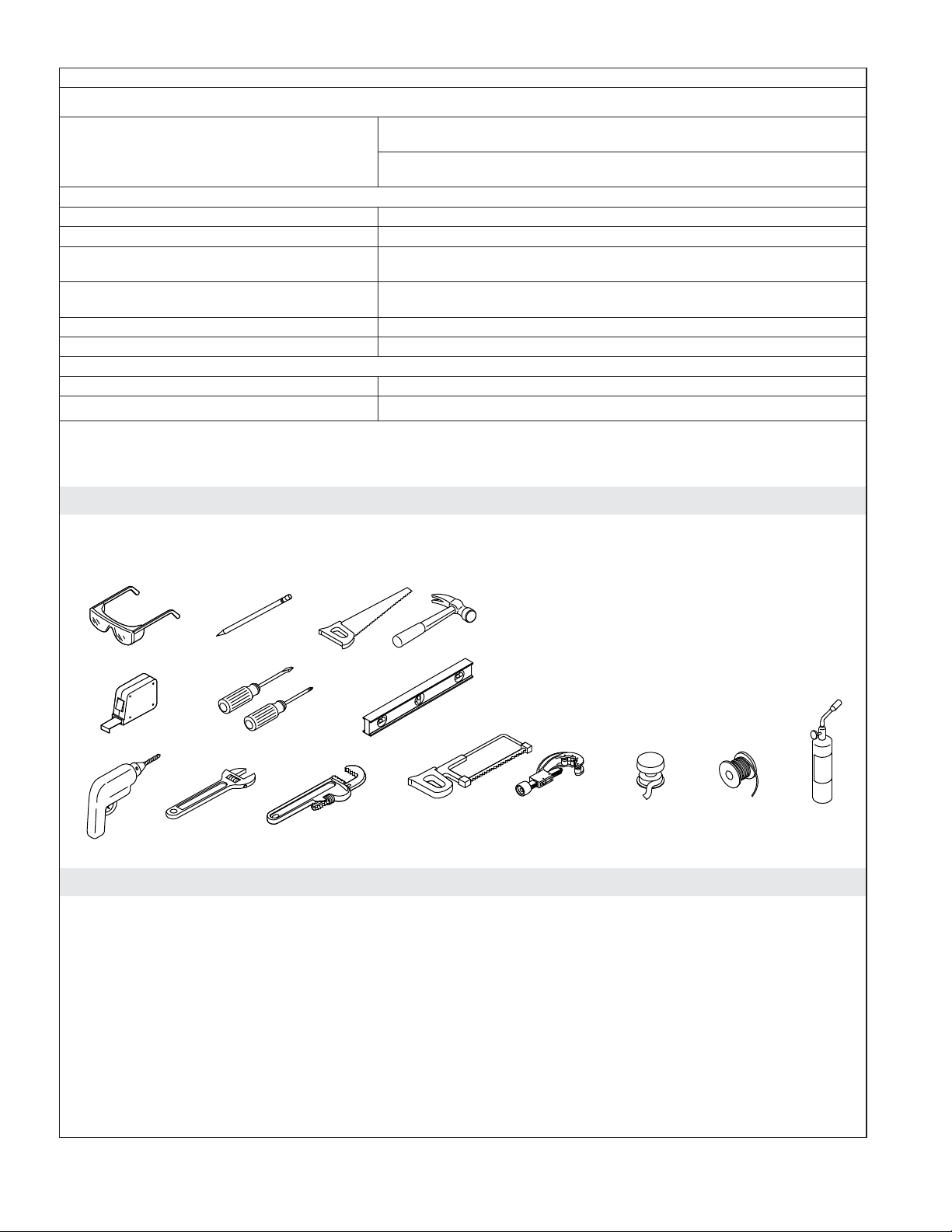
Tools and Materials
Plus:
• (2) 1/2" Union Connectors
• Wood and Framing Materials
• PEX Tubing, Copper Tubing, or PVC
• (2) Water Hammer Arrestors (Recommended)
• (2) Supply Shut-Off Valves
Hacksaw or Tube Cutter Sealant
Tape
Solder Propane
Torch
Before You Begin
NOTICE: Do not install the valve under a whirlpool surround or any location where the temperature may
exceed 104°F (40°C). The valve and its integrated power supply are rated to operate in temperatures up to
104°F (40°C).
NOTICE: Do not apply excessive heat near the valve or apply flux or acids directly onto the valve. This
valve contains plastic and rubber components that will melt if heat is directly applied.
NOTICE: Do not apply petroleum-based lubricants to the valve components. Doing so will damage the
valve components.
NOTICE: Do not use oil-based, nonsetting compounds, such as plumbers putty, on the threaded
connections.
Kohler Co. 3 1240338-2-B
Before You Begin (cont.)
NOTICE: Do not remove the check valves from the inlets as this can damage the product.
NOTICE: If the valve will be used for a bath/shower application, the bath fill supply line must be routed
from the #1 outlet port.
Read these instructions and determine the locations of all required components before beginning
installation. For shower configuration options, refer to the guide on the K-99695 controller product
page at us.kohler.com.
If possible, flush all piping thoroughly before installing the valve. If the pipes are flushed after the
valve is installed, clean the inlet screens before using the system.
A qualified electrician should install a 120 V electrical outlet, within the stud framing, close to the
valve. A GFCI outlet may be required in certain applications.
If possible, install the electrical outlet before installing the valve.
Multiple Valve Applications
Showering configurations using large water volumes require supply piping and drain systems that
will sufficiently accommodate the actual total flow rate at any one time.
Hot water generation: Use a water heating system capable of handling large flow rates. Tankless
(on-demand) water heaters and recirculating pumps may not be adequate for your showering
configuration.
1240338-2-B 4 Kohler Co.
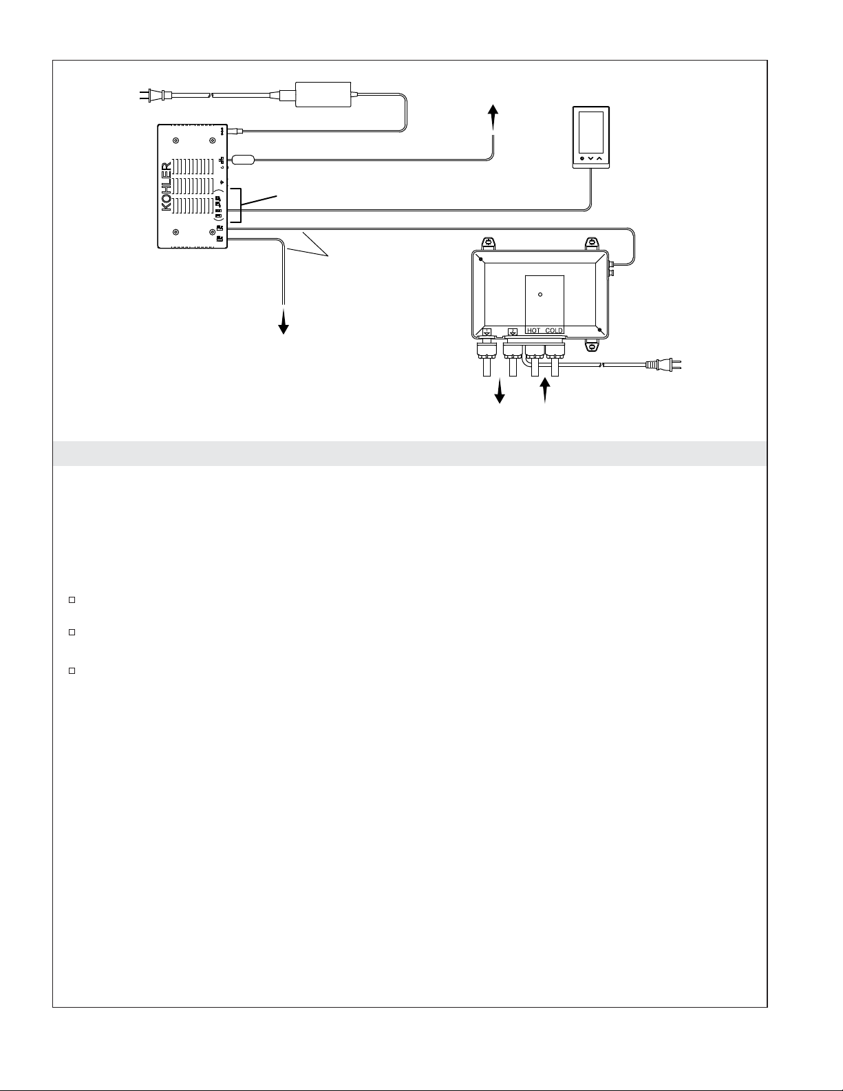
AC Power
Router
Interface
(Up to Three)
Component Cable
Connections
Controller
Digital
Valve
25' (7.6 m)
Data Cable
Digital
Valve
AC Power
Water InletsShower Fittings
1. DTV+ System Layout
The K-99695 system controller powers the interface(s) and controls the digital valve(s) and other system
components. The controller is required to configure the valve(s).
NOTICE: If the valve will be used for a bath/shower application, the bath fill supply line must be routed
from the #1 outlet port.
NOTICE: Custom shower configurations may not allow certain features to be enabled. For shower
configuration options, refer to the guide on the K-99695 controller product page at us.kohler.com.
Determine the locations of all required components, including shower fittings.
A data cable is provided to connect the valve to the controller. If the valve is not within 25’ (7.6 m)
of the controller, obtain a longer telephone-style cable or add an extension cable.
When routing piping, make sure that each shower fitting will connect to the appropriate valve
outlet for your configuration.
Before Operating the System for the First Time:
Download and install the latest software for connected components. This may take an hour or more to
complete based on system configuration and internet connection speed. Do not disconnect the power from
any components during software download and installation.
Kohler Co. 5 1240338-2-B
Inlets
Mounting on a Horizontal SurfaceMounting on a Vertical Surface
Cable
Sockets
Inlets
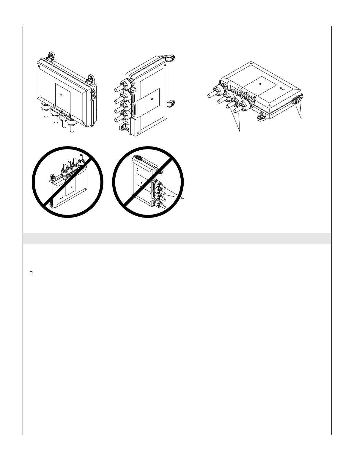
2. Mounting Configurations
NOTICE: Do not mount the valve with the inlets pointing up or positioned above the outlet ports. Doing
so will damage this product.
The two-port valve is shown above. The same vertical or horizontal mounting configurations apply
for the three-port valve.
1240338-2-B 6 Kohler Co.

Cross Brace MountBoard Mount
2-3/4"
(70 mm)
Min
Drip Loop
K-528-K1: 14-1/2"
(368 mm) Min
K-557-K1:
18" (457 mm) Min
Place the outlet
higher than
the valve.
9-1/2"
(241 mm)
Notch bottom brace.
K-528-K1:
14-1/2" (368 mm) Min
K-557-K1:
18" (457 mm) Min
11-5/8"
(295 mm)
12-1/2"
(318 mm)
3. Prepare the Site
NOTICE: Do not install the valve under a whirlpool surround or any location where the temperature may
exceed 104°F (40°C).
NOTE: Horizontal installation within a stud cavity is shown. The valve can also be mounted vertically or
mounted to a horizontal surface. Refer to the ″Mounting Configurations″ section.
K-528-K1: This product is designed to fit within a minimum 14-1/2″ (368 mm) 2x4 stud cavity.
K-557-K1: This product will not fit within a standard stud cavity. Construct a minimum 18″ (457
mm) wide 2x4 stud cavity.
Install adequate bracing for mounting the valve. Notch the bracing as needed to accommodate the
inlets and outlets.
Install a 120 V electrical outlet within the stud framing, close to the valve. Locate the outlet above
the valve. A GFCI outlet may be required in some applications.
Kohler Co. 7 1240338-2-B
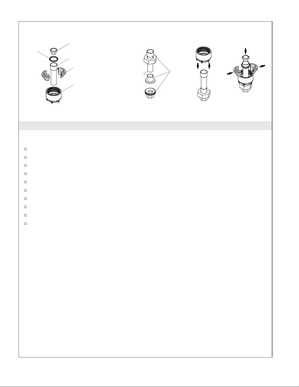
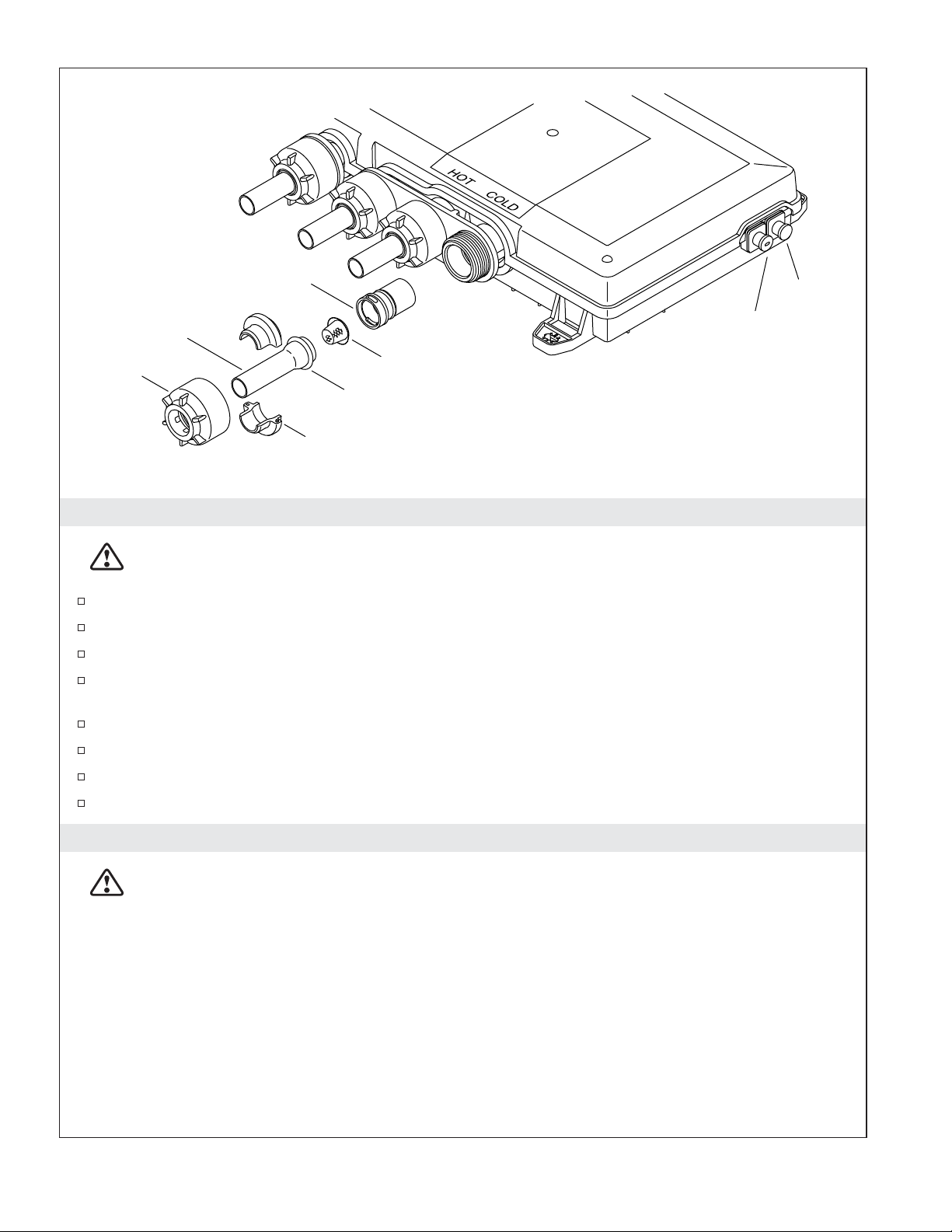
O-Ring
Screen (Inlets Only)
Inlet/Outlet Tube
Adapter Lock
Solder this connection.
Adapter Nut
1/2" Union
4. Assemble the Adapters and Unions
NOTICE: Do not apply excessive heat near the valve or apply flux or acids directly onto the valve. This
valve contains plastic and rubber components that will melt if heat is directly applied.
Disassemble the adapter. Ensure that all rubber and plastic components are removed.
Slide the union nut onto the inlet/outlet tube.
Solder the inlet/outlet tube to the union. Allow to cool completely.
Assemble the union.
Slide the adapter nut onto the inlet/outlet tube.
Assemble the adapter lock onto the inlet/outet tube and slide the assembly into the adapter nut.
Slide the O-ring onto the inlet/outlet tube.
For inlet tubes only: Insert the screen into the end of the inlet tube.
Reinstall the adapter assembly to the valve.
Repeat for all inlet/outlet tubes as required.
1240338-2-B 8 Kohler Co.
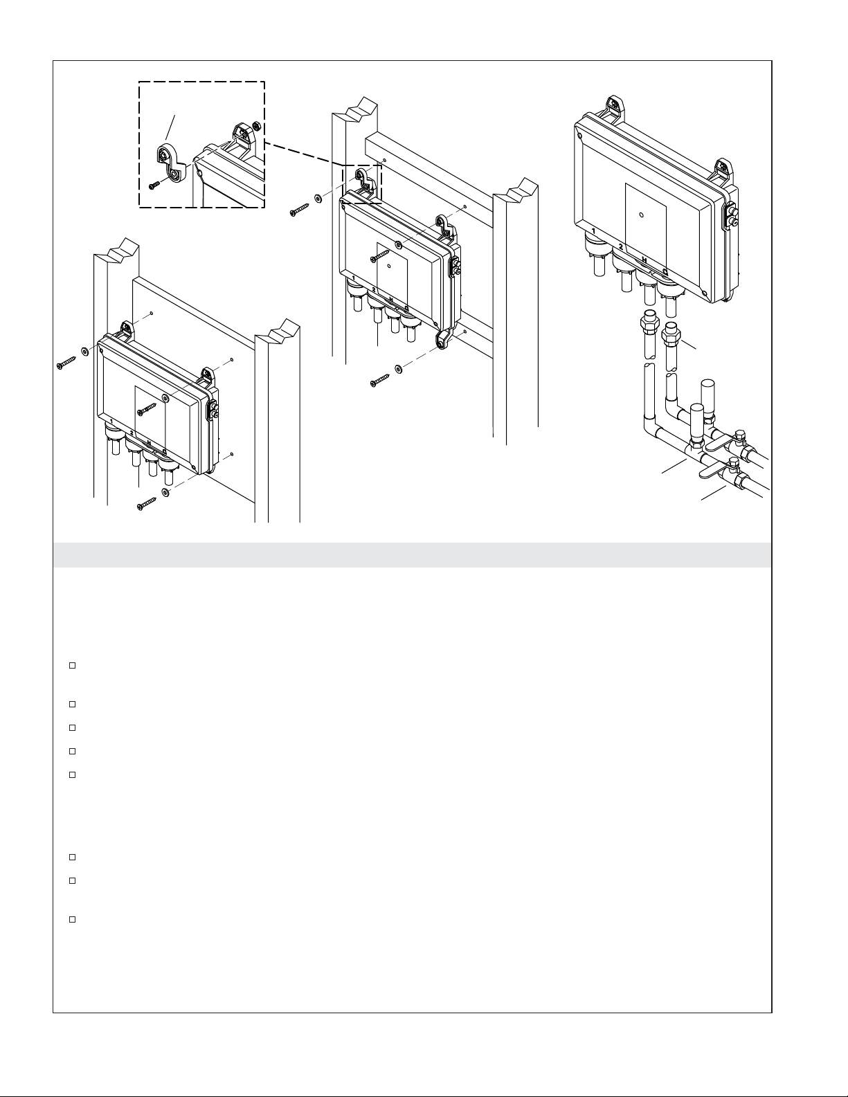
Offset Foot
Board Mount
Cross Brace Mount
1/2" Union
Water-Hammer Arrestor
Shut-Off Valve
5. Install the Valve
NOTICE: Do not apply excessive heat near the valve or apply flux or acids directly onto the valve. This
valve contains plastic and rubber components that will melt if heat is directly applied.
IMPORTANT! If your water supply has high amounts of particulates, install wye strainers in the supply
lines.
Route the water supply lines. Use unions to install removable pipe segments to the valve inlets to
allow access for periodic cleaning of the inlet screens.
Install shut-off valves and water-hammer arrestors in the supply lines before the valve.
Hold the valve up to the installation location. Verify fit and mark the hole locations.
Predrill the holes.
Secure the valve with the washers and screws. Do not overtighten.
IMPORTANT! Make sure that each shower fitting is connected to the appropriate valve outlet for your
shower configuration. For shower configuration options, refer to the guide on the K-99695 controller
product page at us.kohler.com.
Route the piping from the valve outlets to the appropriate shower fitting.
Connect the hot and cold supply lines to the appropriate valve inlets. Hot is red and marked with
″HOT,″ cold is blue and marked with ″COLD.″
Secure all piping to the framing.
Kohler Co. 9 1240338-2-B
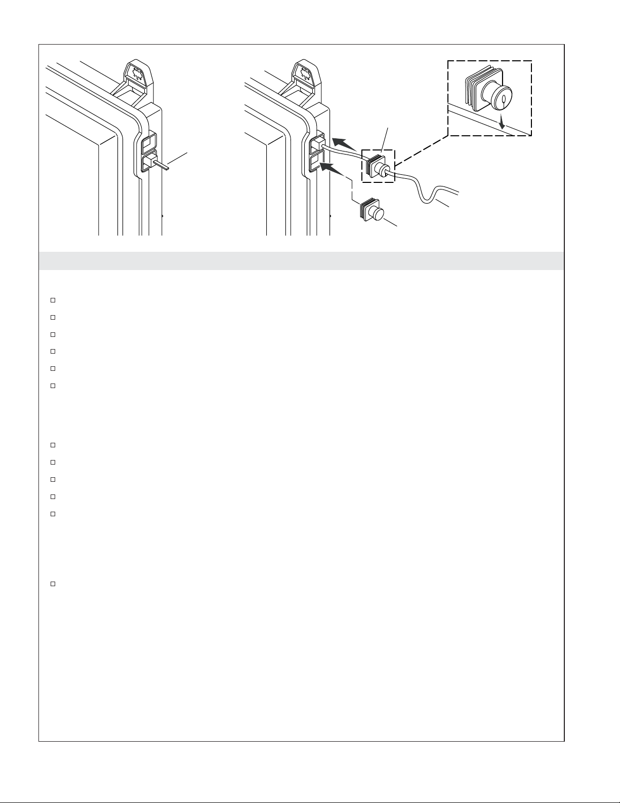
Split
Boot
Jumper
Slide the split boot
onto the cable.
Drip Loop
Solid Boot
6. Installation Checkout
Test for Leaks
Turn on the water supply to the valve.
Connect the jumper to the valve.
Verify that there is power to the 120 V electrical outlet, then plug the power cord into the outlet.
Wait 10 seconds for the valve to initialize; the outlets will activate.
Check all connections for leaks.
Disconnect the power, then remove the jumper.
Connect the Cables
NOTE: Make drip loops in all cables and cords.
Install the K-99695 system controller according to the instructions packed with the product.
Route the data cable in the wall between the controller and valve installation location.
Attach a split boot to the data cable, toward the end that will connect to the valve.
Connect the cable to the valve. Press the boot over the connection in the valve socket.
Insert a solid boot into the unused socket.
Configure the Valve (Requires an Installed Controller)
NOTE: Valves that have been recently installed, or have not been used for some time should be exercised
before running tests or setting the maximum temperature.
To configure valve setup, refer to the guide on the K-99695 controller product page at us.kohler.com.
Before Operating the System for the First Time:
Download and install the latest software for connected components. This may take an hour or more to
complete based on system configuration and internet connection speed. Do not disconnect the power from
any components during software download and installation.
1240338-2-B 10 Kohler Co.
Check Valve
Boot
Copper Tube
Nut
Screen
O-Ring
Seal
Split
Boot
7. Clean the Inlet Screens
CAUTION: Risk of personal injury. The valve may contain hot water; be careful when draining
any residual water.
Disconnect the power and turn off the water supply.
Unthread the plastic nuts from the hot and cold inlets.
Remove the copper tubes. The O-ring and screen may be attached to the end of the tube.
If the screen remains in the check valve, use a small flat-blade screwdriver to gently pull the check
valve from the valve inlet.
Remove the screens from the copper tubes or check valves.
Clean the screens to remove any dirt or debris.
Rinse or replace the check valves and screens.
Reassemble the inlet connections.
Troubleshooting
WARNING: Risk of electric shock. Disconnect power before servicing.
NOTICE: Valve maintenance should be performed by a KOHLER Authorized Service Representative
(ASR).
NOTE: For DTV+ system troubleshooting, refer to the guide on the K-99695 controller product page at
us.kohler.com.
NOTE: For service parts information, visit your product page at kohler.com/serviceparts.
This troubleshooting guide is for general aid only. For service and installation issues or concerns, call
1-800-4KOHLER.
Kohler Co. 11 1240338-2-B
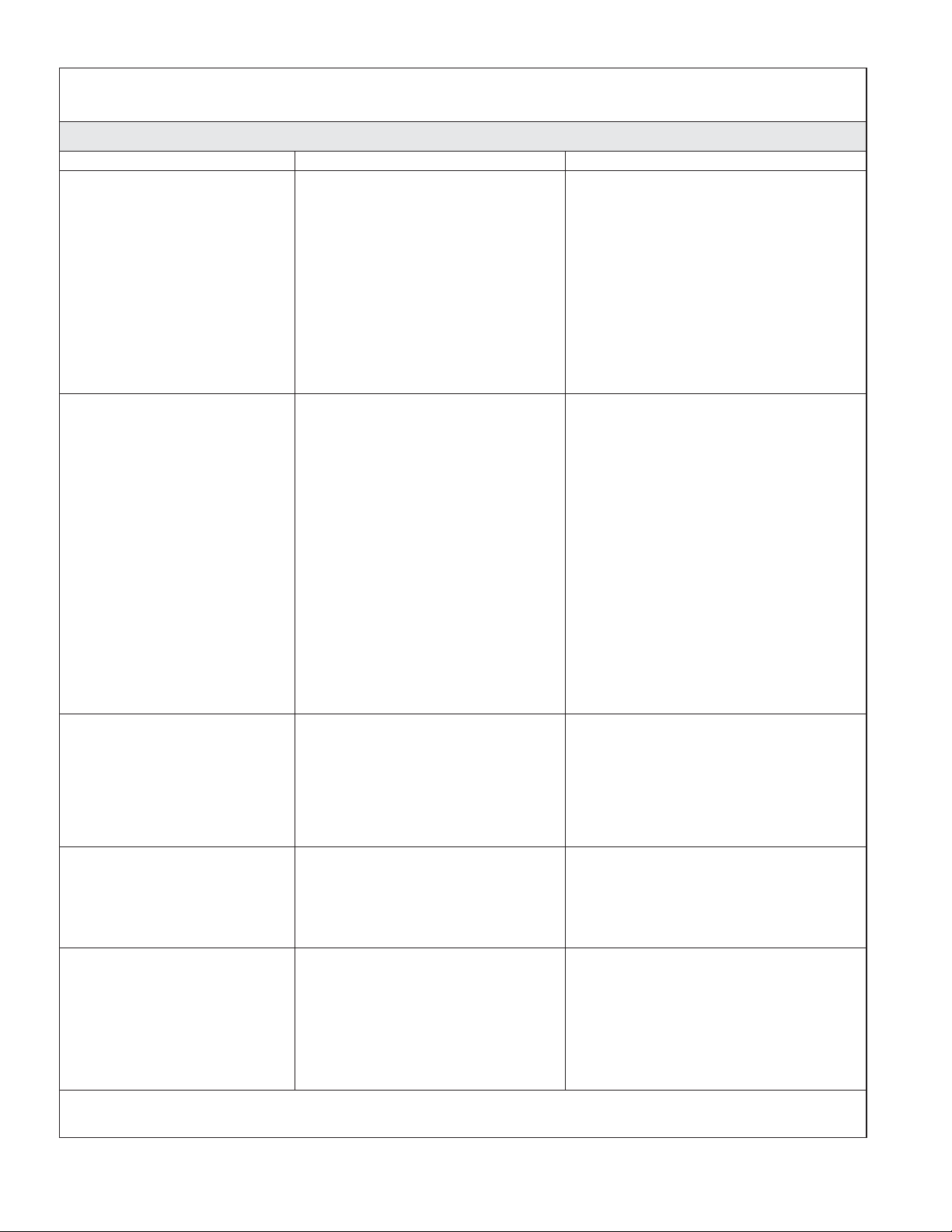
Troubleshooting (cont.)
Troubleshooting Table
Symptoms Probable Cause Recommended Action
1. Valve will not turn on. A. Valve is not plugged into the
2. The interface functions
normally but no water
flows from the shower
fittings.
3. Maximum blend
temperature too hot or
too cold.
4. Continuous flow. A. System will not switch off. A. Turn off the water and power
5. Only cold water flows
from the outlets.
outlet.
B. Data cable connection may be
loose or disconnected.
C. Circuit breaker has been
tripped.
D. The valve memory may require
resetting.
E. If none of the recommended
actions for the above issues
correct the symptom, the valve
or interface requires servicing.
A. Valve outlets may be blocked. A. Check the valve outlets for
B. Fittings/sprayfaces may be
blocked.
C. Hot and cold water supplies are
not turned on.
D. The valve memory may require
resetting.
E. System error. E. Check the user interface for an
F. If none of the recommended
actions for the above issues
correct the symptom, the valve
requires servicing.
A. Incorrect maximum temperature
setting.
B. If the above recommended
action does not correct the
symptom, the interface or valve
requires servicing.
B. Flow rate exceeds 10 gal/min
(45.5 l/min) from one outlet.
A. Hot water supply is either not
turned on or not connected to
the valve inlet.
B. Hot water inlet is blocked. B. Check the hot water inlet screen for
C. The hot water supply is
exhausted.
A. Plug the valve into an outlet.
B. Check the data cable connection,
connect if needed.
C. Reset the circuit breaker.
D. Disconnect and reconnect the valve
power cord from the electrical
outlet.
E. Contact your Kohler Co.
Authorized Service Representative
(ASR).
blockage or debris. Clean the outlet
screens.
B. Clean the sprayfaces and any
screens in your fittings.
C. Turn on the water supply to the
valve.
D. Disconnect and reconnect the valve
power cord from the electrical
outlet.
error code. Refer to the guide on
the K-99695 controller product page
at us.kohler.com.
F. Contact your Kohler Co.
Authorized Service Representative
(ASR).
A. Set the maximum temperature.
Refer to the guide on the K-99695
controller product page at
us.kohler.com.
B. Contact your Kohler Co.
Authorized Service Representative
(ASR).
supply and contact your Kohler Co.
Authorized Service Representative
(ASR).
B. Ensure that flow restrictors are
installed in both outlets.
A. Check if the hot water supply is
turned on and connected to the
valve inlet.
blockage. Clean or replace the inlet
screen.
C. Allow time for the water heater to
come up to temperature.
1240338-2-B 12 Kohler Co.
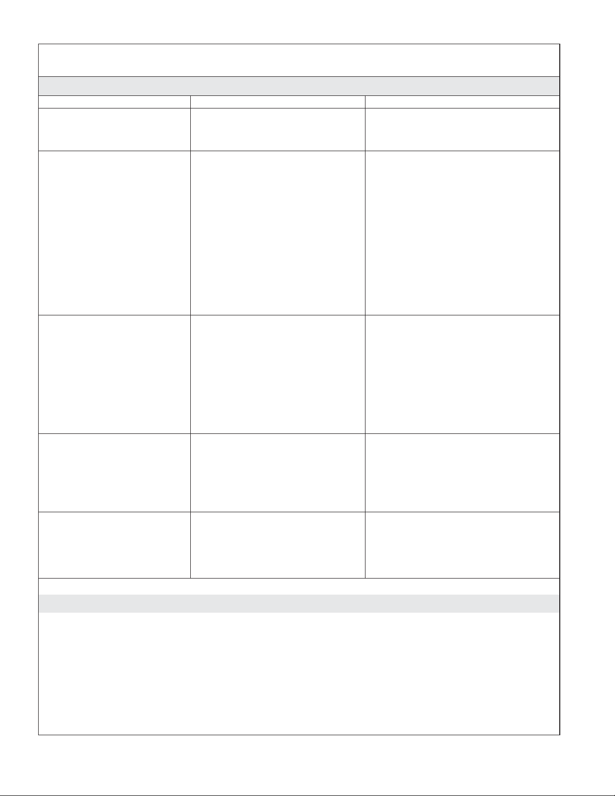
Troubleshooting (cont.)
Troubleshooting Table
Symptoms Probable Cause Recommended Action
6. Fluctuating or reduced
flow rate. Valve is
functioning properly.
7. Blend temperature drift or
temperature cycling.
8. Water leaking from the
valve.
CAUTION: Risk of
personal injury or
product damage. Turn off
the main power and
water supply.
9. Hot water only, the valve
shuts down.
D. If none of the recommended
actions for the above issues
correct the symptom, the valve
requires servicing.
A. Valve inlets may be blocked. A. Check the valve inlets for blockage
B. Fittings/Sprayfaces may be
blocked.
C. Water outlet pressure is low. C. Check that the flow rate is at or
D. Fluctuating supply pressure. D. Verify that the dynamic inlet
E. Water supply temperatures are
not within the recommended
range.
A. Fluctuating water supply
temperature.
B. Pressure difference greater than
5 psi (34.5 kPa) between the hot
and cold supply lines.
C. If none of the recommended
actions for the above issues
correct the symptom, the valve
requires servicing.
A. Connections are not secure. A. Check all connections. Make
B. Seals are worn or damaged. B. Order a seal service pack and
C. Internal leak. C. Unit requires overhaul. Contact
A. Hot and cold lines are reversed. A.
D. Contact your Kohler Co.
Authorized Service Representative
(ASR).
or debris. Clean the inlet screens.
Refer to the ″Clean the Inlet
Screens″ section.
B. Clean the sprayfaces and any
screens in your fittings.
above the minimum rate required.
Refer to ″Specifications″ section.
pressures are within specifications.
Refer to ″Specifications″ section.
E. Check if inlet water temperatures
are within the recommended range.
A. Check the inlet temperature
differentials and verify that they
are sufficient. Refer to
″Specifications″ section.
B. Install pressure regulators to bring
the supplies within 5 psi (34.5 kPa)
of each other.
C. Contact your Kohler Co.
Authorized Service Representative
(ASR).
adjustments as needed.
replace all seals.
your Kohler Co. Authorized Service
Representative (ASR).
Switch hot and cold water supply
connections. Verify that the hot
water supply is connected to the
″Hot″ inlet and the cold water
supply is connected to the ″Cold″
inlet.
FCC, IC, and CE Compliance
Contains: Kohler Company, Model: K-528-PM-NA, FCC ID: SH6MDBT40, IC: 8017A-MDBT40
FCC Interference Statement
This device complies with Part 15 of the FCC Rules. Operation is subject to the following two conditions:
1. This device may not cause harmful interference, and
2. This device must accept any interference received, including interference that may cause undesired
operation.
Kohler Co. 13 1240338-2-B

FCC, IC, and CE Compliance (cont.)
Changes or modifications not expressly approved by the party responsible for compliance could void the
user’s authority to operate the equipment.
This equipment has been tested and found to comply with the limits for a Class B digital device, pursuant to
Part 15 of the FCC Rules. These limits are designed to provide reasonable protection against harmful
interference in a residential installation. This equipment generates, uses, and can radiate radio frequency
energy and, if not installed and used in accordance with the instructions, may cause harmful interference to
radio communications. However, there is no guarantee that interference will not occur in a particular
installation. If this equipment does cause harmful interference to radio or television reception, which can be
determined by turning the equipment off and on, the user is encouraged to try to correct the interference by
one or more of the following measures:
•
Reorient or relocate the receiving antenna.
•
Increase the separation between the equipment and receiver.
•
Connect the equipment into an outlet on a circuit different from that to which the receiver is
connected.
•
Consult the dealer or an experienced radio/TV technician for help.
Industry Canada Statement
This device complies with Industry Canada licence-exempt RSS standard(s). Operation is subject to the
following two conditions:
1. This device may not cause interference, and
2. This device must accept any interference, including interference that may cause undesired operation of the
device.
CAN ICES-3(B) /NMB-3(B)
CE2200
Warranty
KOHLER®Electronic Faucets, Valves and Controls
FIVE-YEAR LIMITED WARRANTY
Kohler Co. warrants that its electronic faucets, valves and controls will be free of defects in material and
workmanship during normal residential use for five years from the date the product is installed. This
warranty applies only to electronic faucets, valves and controls installed in the United States of America,
Canada and Mexico (″North America″).
If a defect is found in normal residential use, Kohler Co. will, at its election, repair, provide a replacement
part or product, or make appropriate adjustment where Kohler Co.’s inspection discloses any such defect.
Damage caused by accident, misuse, or abuse is not covered by this warranty. Improper care and cleaning
will void the warranty*. Proof of purchase (original sales receipt) must be provided to Kohler Co. with all
warranty claims. Kohler Co. is not responsible for labor charges, installation, or other incidental or
consequential costs other than those noted above. In no event shall the liability of Kohler Co. exceed the
purchase price of the faucet, valve or control.
If the electronic faucets, valves or controls are used commercially or are installed outside of North America,
Kohler Co. warrants that the faucet, valve or control will be free from defects in material and workmanship
for one (1) year from the date the product is installed, with all other terms of this warranty applying except
duration.
If you believe that you have a warranty claim, contact your Home Center, Dealer, Plumbing Contractor or
E-tailer. Please be sure to provide all pertinent information regarding your claim, including a complete
description of the problem, the product, model number, the date the product was purchased, from whom the
product was purchased and the installation date. Also include your original invoice. For other information,
or to obtain the name and address of the service and repair facility nearest you, write Kohler Co., Attn:
Customer Care Center, Kohler, Wisconsin 53044 USA, or by calling 1-800-4-KOHLER (1-800-456-4537) from
within the USA and Canada, and 001-800-456-4537 from within Mexico, or visit www.kohler.com within the
1240338-2-B 14 Kohler Co.

Warranty (cont.)
USA, www.ca.kohler.com from within Canada, or www.mx.kohler.com in Mexico.
THE FOREGOING WARRANTIES ARE IN LIEU OF ALL OTHER WARRANTIES, EXPRESS OR
IMPLIED, INCLUDING BUT NOT LIMITED TO THE IMPLIED WARRANTIES OF
MERCHANTABILITY AND FITNESS FOR A PARTICULAR PURPOSE.
KOHLER CO. AND/OR SELLER DISCLAIM ANY LIABILITY FOR SPECIAL, INCIDENTAL OR
CONSEQUENTIAL DAMAGES. Some states/provinces do not allow limitations on how long an implied
warranty lasts or the exclusion or limitation of such damages, so these limitations and exclusions may not
apply to you. This warranty gives the consumer specific legal rights. You may also have other rights that
vary from state/province to state/province. This warranty is to the original consumer purchaser only, and
excludes product damage due to installation error, product abuse, or product misuse, whether performed
by a contractor, service company, or the consumer.
This is Kohler Co.’s exclusive written warranty.
*Never use cleaners containing abrasive cleansers, ammonia, bleach, acids, waxes, alcohol, solvents or
other products not recommended for chrome. This will void the warranty.
Kohler Co. 15 1240338-2-B
 Loading...