

Page 1
COMMAND PRO
CH940-CH980
HORIZONTAL CRANKSHAFT
SERVICE MANUAL
Page 2

Contents
Section 1. Safety and General Information ............................................................................
Section 2. T ools & Aids ............................................................................................................
Section 3. Troubleshooting .....................................................................................................
Section 4. Air Cleaner and Air Intake System ........................................................................
Section 5. Fuel System and Governor....................................................................................
Section 6. Lubrication System ................................................................................................
Section 7. Electrical System and Components......................................................................
1
2
3
4
5
6
7
Section 8. Disassembly............................................................................................................
Section 9. Inspection and Reconditioning .............................................................................
Section 10. Reassembly ..........................................................................................................
8
9
10
Page 3
Section 1
Safety and General Information
Section 1
Safety and General Information
Safety Precautions
To ensure safe operation please read the following statements and understand their meaning. Also
refer to your equipment manufacturer's manual for other important safety information. This manual
contains safety precautions which are explained below. Please read carefully.
WARNING
Warning is used to indicate the presence of a hazard that can cause severe personal injury, death,
or substantial property damage if the warning is ignored.
CAUTION
Caution is used to indicate the presence of a hazard that will or can cause minor personal injury or
property damage if the caution is ignored.
NOTE
Note is used to notify people of installation, operation, or maintenance information that is important
but not hazard-related.
1
For Y our Safety!
These precautions should be followed at all times. Failure to follow these precautions could result in injury to yourself
and others.
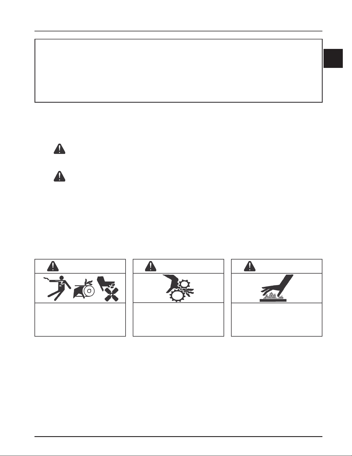
WARNING
Accidental Starts can cause severe
injury or death.
Disconnect and ground spark plug
leads before servicing.
Accidental Starts!
Disabling engine. Accidental starting
can cause severe injury or death.
Before working on the engine or
equipment, disable the engine as follows:
1) Disconnect the spark plug lead(s).
2) Disconnect negative (-) battery cable
from battery.
WARNING
Rotating Parts can cause severe
injury.
Stay away while engine is in
operation.
Rotating Parts!
Keep hands, feet, hair, and clothing away
from all moving parts to prevent injury.
Never operate the engine with covers,
shrouds, or guards removed.
Hot Parts can cause severe burns.
Do not touch engine while operating
or just after stopping.
Hot Parts!
Engine components can get extremely
hot from operation. To prevent severe
burns, do not touch these areas while the
engine is running - or immediately after it
is turned off. Never operate the engine
with heat shields or guards removed.
WARNING
1.1
Page 4
Section 1
Safety and General Information
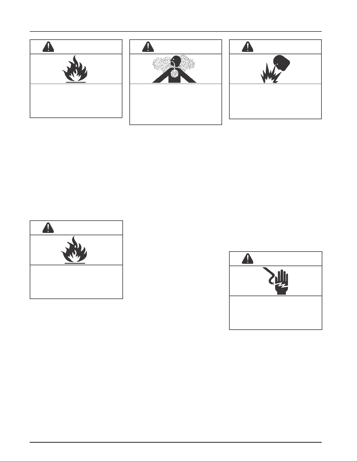
WARNING
Explosive Fuel can cause fires and
severe burns.
Do not fill the fuel tank while the
engine is hot or running.
Explosive Fuel!
Gasoline is extremely flammable and its
vapors can explode if ignited. Store
gasoline only in approved containers, in
well ventilated, unoccupied buildings,
away from sparks or flames. Do not fill
the fuel tank while the engine is hot or
running, since spilled fuel could ignite if
it comes in contact with hot parts or
sparks from ignition. Do not start the
engine near spilled fuel. Never use
gasoline as a cleaning agent.
WARNING
WARNING WARNING
Carbon Monoxide can cause severe
nausea, fainting or death.
Avoid inhaling exhaust fumes, and
never run the engine in a closed
building or confined area.
Lethal Exhaust Gases!
Engine exhaust gases contain poisonous
carbon monoxide. Carbon monoxide is
odorless, colorless, and can cause death if
inhaled. Avoid inhaling exhaust fumes,
and never run the engine in a closed
building or confined area.
Explosive Gas can cause fires and
severe acid burns.
Charge battery only in a well
ventilated area. Keep sources of
ignition away.
Explosive Gas!
Batteries produce explosive hydrogen gas
while being charged. To prevent a fire or
explosion, charge batteries only in well
ventilated areas. Keep sparks, open
flames, and other sources of ignition
away from the battery at all times. Keep
batteries out of the reach of children.
Remove all jewelry when servicing
batteries.
Before disconnecting the negative (-)
ground cable, make sure all switches are
OFF. If ON, a spark will occur at the
ground cable terminal which could cause
an explosion if hydrogen gas or gasoline
vapors are present.
Cleaning Solvents can cause severe
injury or death.
Use only in well ventilated areas
away from ignition sources.
Flammable Solvents!
Carburetor cleaners and solvents are
extremely flammable. Keep sparks,
flames, and other sources of ignition
away from the area. Follow the cleaner
manufacturer’s warnings and
instructions on its proper and safe use.
Never use gasoline as a cleaning agent.
CAUTION
Electrical Shock can cause injury.
Do not touch wires while engine is
running.
Electrical Shock!
Never touch electrical wires or
components while the engine is running.
They can be sources of electrical shock.
1.2
Page 5
Engine Identification Numbers
When ordering parts, or in any communication
involving an engine, always give the Model,
Specification, and Serial Numbers, including letter
suffixes if there are any.
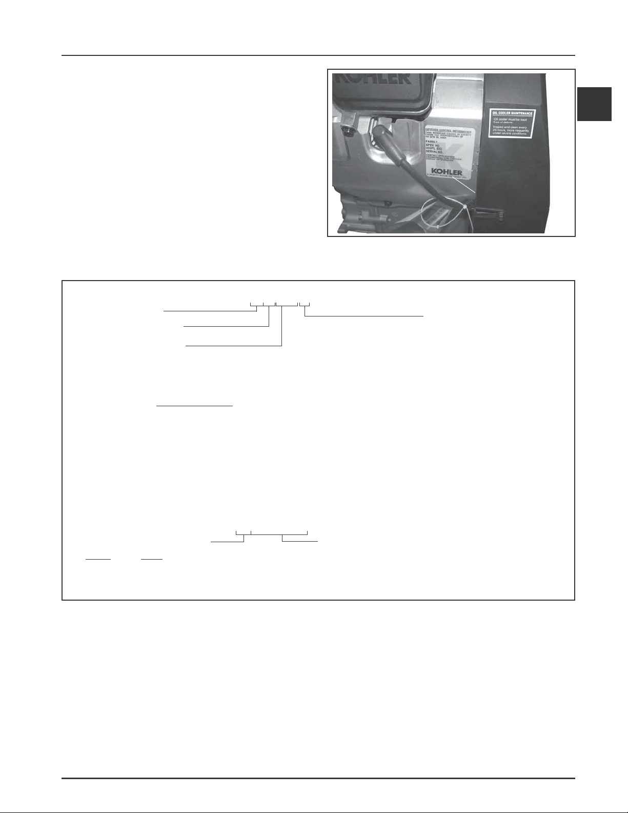
The engine identification numbers appear on a decal,
or decals, affixed to the engine shrouding. See Figure
1-1. An explanation of these numbers is shown in
Figure 1-2.
Section 1
Safety and General Information
1
Identification
Decal
Figure 1-1. Engine Identification Decal Location.
A . Model No.
Command Engine
Horizontal Crankshaft
Numerical Designation
B. Spec. No.
C. Serial No.
Year Manufactured Code
Code Year
37 2007
38 2008
C H 980 S
Version Code
S = Electric Start
CH940-0001
CH960-0001
CH980- 0001
Complete Spec. Number
(Incorporating Model No.
with V ariation No. of
Basic Spec.)
3705810334
Factory Code
Figure 1-2. Explanation of Engine Identification Numbers.
1.3
Page 6
Section 1
Safety and General Information
Oil Recommendations
Using the proper type and weight of oil in the
crankcase is extremely important. So is checking oil
daily and changing oil regularly. It is also
recommended that a consistent brand of oil be used.
Failure to use the correct oil, or using dirty oil, causes
premature engine wear and failure.
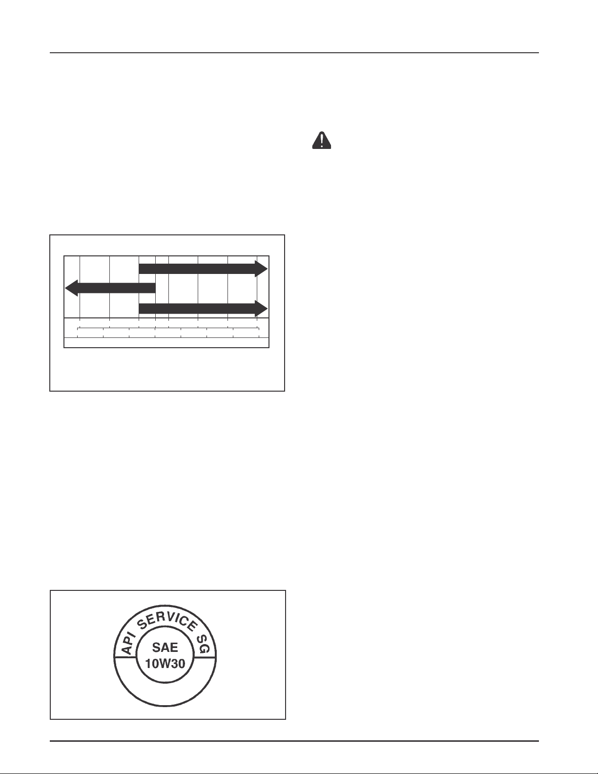
Oil Type
Use high-quality detergent oil of API (American
Petroleum Institute) Service Class SG, SH, SJ or
higher. Select the viscosity based on the air
temperature at the time of operation as shown in the
following table.
RECOMMENDED SAE VISCOSITY GRADES
10W-30
**
5W-20, 5W-30
°F -20 0 20 32 40 60 80 100
°C -30 -20 -10 0 10 20 30 40
TEMPERATURE RANGE EXPECTED BEFORE NEXT OIL CHANGE
* Use of synthetic oil having 5W-20 or 5W-30 rating is acceptable,
up to 4°C (40°F)
** Synthetic oils will provide better starting in extreme cold below
23°C (-10°F)
NOTE: Using other than service class SG, SH, SJ or
higher oil or extending oil change intervals
longer than recommended can cause engine
damage.
NOTE: Synthetic oils meeting the listed
classifications may be used with oil changes
performed at the recommended intervals.
However, to allow piston rings to properly
seat, a new or rebuilt engine should be
operated for at least 50 hours using standard
petroleum based oil before switching to
synthetic oil.
A logo or symbol on oil containers identifies the API
service class and SAE viscosity grade. See Figure 1-3.
*
Kohler 10W-30
Refer to Section 6 - Lubrication System for detailed
procedures on checking the oil, changing the oil and
changing the oil filter.
Fuel Recommendations
WARNING: Explosive Fuel!
Gasoline is extremely flammable and its vapors can explode if
ignited. Before servicing the fuel system, make sure there are no
sparks, open flames or other sources of ignition nearby as these
can ignite gasoline vapors. Disconnect and ground the spark
plug leads to prevent the possibility of sparks from the ignition
system.
General Recommendations
Purchase gasoline in small quantities that can be used
within 30 days, and store only in clean, approved
containers. Do not use gasoline left over from the
previous season, unless treated with a fuel stabilizer
(see Storage), to minimize gum deposits and ensure
easy starting. Do not use gasoline containing
Methanol, or add oil to the gasoline.
Do not overfill the fuel tank. Leave room for the fuel to
expand.
Fuel Type
For best results, use only clean, fresh, unleaded
gasoline with a pump sticker octane rating of 87 or
higher. In countries using the Research method, it
should be 90 octane minimum.
Unleaded gasoline is recommended as it leaves less
combustion chamber deposits and reduces harmful
exhaust emissions. Leaded gasoline is not
recommended and must not be used on EFI engines, or
on other models where exhaust emissions are
regulated.
Gasoline/Alcohol Blends
Gasohol (up to 10% ethyl alcohol, 90% unleaded
gasoline by volume) is approved as a fuel for Kohler
engines. Other gasoline/alcohol blends including E20
and E85 are not to be used and not approved. Any
failures resulting from use of these fuels will not be
warranted.
Figure 1-3. Oil Container Logo.
1.4
Gasoline/Ether Blends
Methyl Tertiary Butyl Ether (MTBE) and unleaded
gasoline blends (up to a maximum of 15% MTBE by
volume) are approved as a fuel for Kohler engines.
Other gasoline/ether blends are not approved.
Page 7

Periodic Maintenance Instructions
Section 1
Safety and General Information
WARNING: Accident al St arts!
Disabling engine. Accidental starting can cause severe injury or death. Before working on the engine or equipment, disable
the engine as follows: 1) Disconnect the spark plug lead(s). 2) Disconnect negative (-) battery cable from battery.
Maintenance Schedule
These required maintenance procedures should be performed at the frequency stated in the table. They should
also be included as part of any seasonal tune-up.
Frequency
Daily or Before
Starting Engine
Weekly
Seasonally or
Every 150 Hours
Every 200 Hours
Seasonally or
Every 300 Hours
Yearly or
Every 500 Hours
Every 600 Hours
¹Perform these maintenance procedures more frequently under extremely dusty, dirty conditions.
2
Have a Kohler Engine Service Dealer perform this service.
Maintenance Refer to:
• Fill fuel tank. Section 5
• Check oil level. Section 6
• Check air cleaner for dirty1, loose, or damaged parts. Section 4
• Check air intake and cooling areas, clean as necessary. Section 4
• Check filter minder or air cleaner element. Section 4
• Check air cleaner element. Section 4
• Replace fuel filter. Section 5
• Change oil. Oil filter is recommended.
(More frequently under severe conditions.) Section 6
• Remove cooling shrouds and clean cooling areas1. Section 4
• Check oil cooler fins, clean as necessary. Section 6
• Check spark plug condition and gap. Section 7
• Change oil filter. Section 6
• Replace air cleaner element. Section 4
• Have solenoid shift starter disassembled and cleaned2. Section 7
• Have crankshaft splines lubricated2.
• Replace inner air cleaner element. Section 4
• Replace spark plugs. Section 7
1
Storage
If the engine will be out of service for 30 days or more,
use the following storage procedure.
1. Clean the exterior surfaces of the engine. Avoid
spraying water at the wiring harness or any of
the electrical components.
2. Change the oil and oil filter while the engine is
still warm from operation. See Changing Oil and
Oil Filter in Section 6.
3. The fuel system must be completely emptied, or
the gasoline must be treated with a stabilizer to
prevent deterioration. If you choose to use a
stabilizer, follow the manufacturer’s
recommendations, and add the correct amount
for the capacity of the fuel system.
Fill the fuel tank with clean, fresh gasoline. Run
the engine for 2 to 3 minutes to get stabilized fuel
into the rest of the system. Close the fuel shut-off
valve when the unit is being stored or
transported.
To empty the system, run the engine until the
tank and the system are empty.
4. Remove the spark plugs and add one tablespoon
of engine oil into each spark plug hole. Install the
spark plugs, but do not connect the plug leads.
Crank the engine two or three revolutions.
5. Disconnect the battery or use a battery minder to
keep the battery charged during storage.
6. Store the engine in a clean, dry place.
1.5
Page 8
Section 1
Safety and General Information
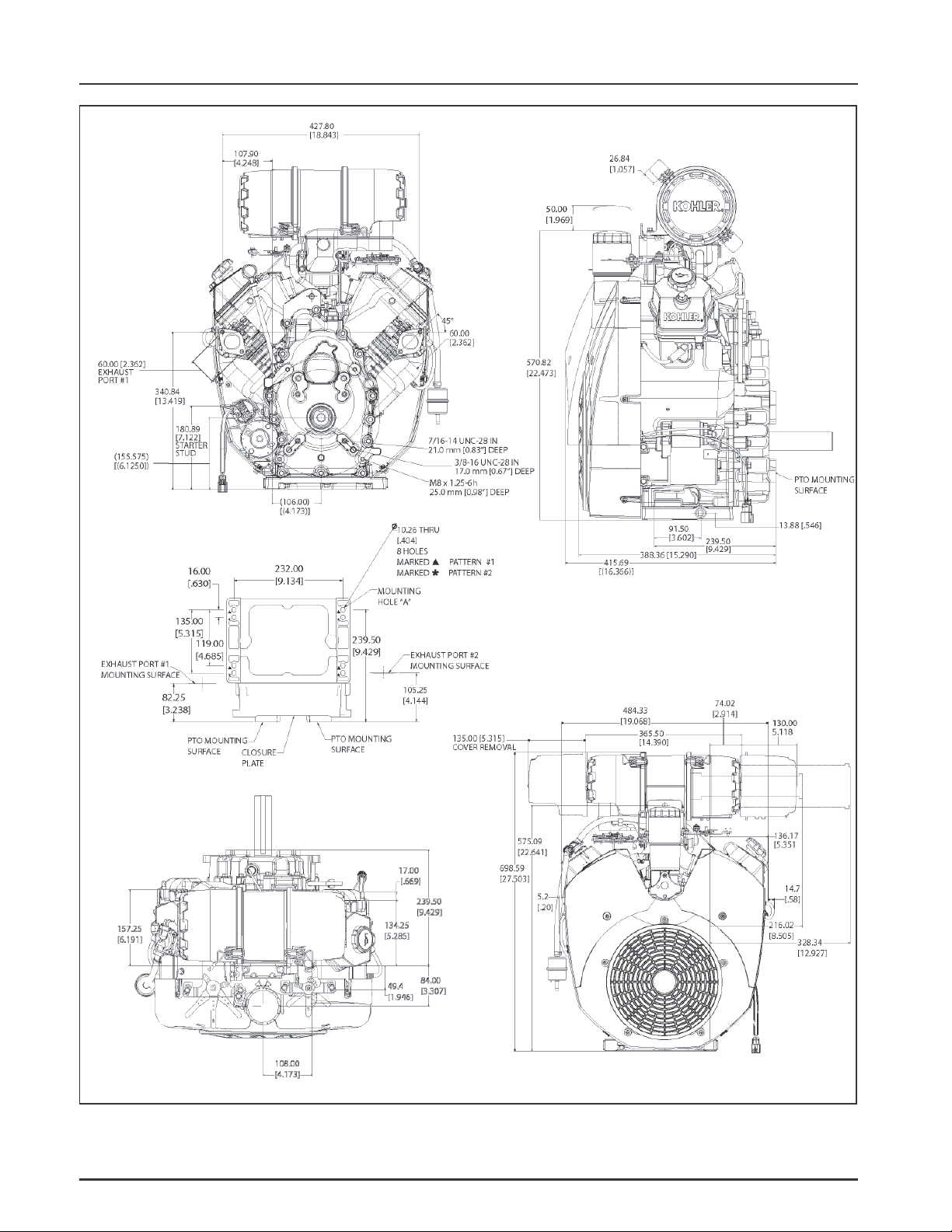
Dimensions in millimeters.
Inch equivalents shown in [ ].
Figure 1-4. T ypical CH PRO Series Engine Dimensions with Heavy-Duty Air Cleaner.
1.6
Page 9

Safety and General Information
General Specifications¹
Power (@ 3600 RPM, exceeds Society of Automotive Engineers-Small Engine Test Code J1940.)
CH940 ........................................................................................................25.4 kW (34 HP)
CH960 ........................................................................................................26.9 kW (36 HP)
CH980 ........................................................................................................28.3 kW (38 HP)
Bore ...................................................................................................................90 mm (3.54 in.)
Stroke ................................................................................................................ 78.5 mm (3.1 in.)
Displacement ...................................................................................................999 cc (61 cu. in.)
Compression Ratio ......................................................................................... 8.8:1
Dry Weight ......................................................................................................59.8 kg (132 lb.)
Oil Capacity (w/filter) - approximate,
determined by oil filter used ........................................................................ 2.7 L (2.9 U.S. qt.)
Angle of Operation - Maximum (At Full Oil Level) All Directions ......... 25°
Section 1
1
Blower Housing and Sheet Metal
M6 Shoulder Screw Torque
New, Untapped Hole (casting) .............................................................. 10.7 N·m (95 in. lb.)
Used, Tapped Hole (casting) ................................................................... 7.3 N·m (65 in. lb.)
New, Extruded Hole (sheet metal) ........................................................ 4.0 N·m (35 in. lb.)
Used, Extruded Hole (sheet metal) ........................................................ 2.0 N·m (17.7 in. lb.)
Mounting Clip (valley baffle)................................................................. 2.5 N·m (22.1 in. lb.)
M6 Screw Torque
New, Untapped Hole (casting) .............................................................. 10.7 N·m (95 in. lb)
Used, Tapped Hole (casting) ...................................................................7.3 N·m (65 in. lb)
Rectifier-Regulator Fastener Torque ........................................................... 2.0 N·m (18 in. lb.)
Oil Cooler Fastener Torque ............................................................................ 2.2 N·m (20 in. lb.)
Camshaft
End Play ...........................................................................................................0.3/1.3 mm (0.011/0.051 in.)
Running Clearance ......................................................................................... 0.025/0.063 mm (0.0010/0.0025 in.)
Bore I.D.
New ........................................................................................................... 20.000/20.025 mm (0.7874/0.7884 in.)
Max. Wear Limit ...................................................................................... 20.038 mm (0.7889 in.)
Camshaft Bearing Surface O.D.
New ........................................................................................................... 19.962/19.975 mm (0.7859/0.7864 in.)
Max. Wear Limit ...................................................................................... 19.959 mm (0.7858 in.)
Cam Lobe Profile (Minimum Dimension, Measured From Base Circle To Top Of Lobe)
Exhaust ............................................................................................................. 35 mm (1.3779 in.)
Intake ................................................................................................................35 mm (1.3779 in.)
¹Values are in Metric units. Values in parentheses are English equivalents. Lubricate threads with engine oil
prior to assembly.
1.7
Page 10

Section 1
Safety and General Information
Carburetor, Intake Manifold, and Air Cleaner
Intake Manifold Mounting Fastener Torque
Torque (Using Sequence) in Two Stages ...............................................first to 16.9 N·m (150 in. lb.)
finally to 22.6 N·m (200 in. lb.)
Carburetor/Air Cleaner Mounting Nut Torque .........................................7.9 N·m (70 in. lb.)
Air Cleaner Mounting Screw Torque (Into Intake Manifold) ...................9.9 N·m (88 in. lb.)
Control Bracket
Mounting Screw (Into Intake Manifold from Air Cleaner) Torque ......... 9.9 N·m (88 in. lb.)
Connecting Rod
Cap Fastener Torque (Torque In Increments) ............................................. 11.3 N·m (100 in. lb.)
Crankpin End I.D. @ 70°F
New ........................................................................................................... 44.030/44.037 mm (1.7334/1.7337 in.)
Max. Wear Limit ...................................................................................... 0.070 mm (0.0028 in.)
Connecting Rod-to-Crankpin Running Clearance
New ........................................................................................................... 0.030/0.055 mm (0.0012/0.0022 in.)
Max. Wear Limit ...................................................................................... 0.070 mm (0.0028 in.)
Connecting Rod-to-Crankpin Side Clearance ............................................ 0.30/0.59 mm (0.0118/0.0232 in.)
Connecting Rod-to-Piston Pin Running Clearance................................... 0.015/0.028 mm (0.0006/0.0011 in.)
Piston Pin End I.D. @ 70°F
New ........................................................................................................... 19.023/19.015 mm (0.7489/0.7486 in.)
Max. Wear Limit ...................................................................................... 19.036 mm (0.7494 in.)
Crankcase
Governor Cross Shaft Bore I.D.
New ........................................................................................................... 8.025/8.050 mm (0.3159/0.3169 in.)
Max. Wear Limit ...................................................................................... 8.088 mm (0.3184 in.)
Breather Cover Fastener Torque .................................................................. 5.7 N·m (51 in. lb.)
Oil Drain Plug Torque .................................................................................... 21.4 N·m (15.7 ft. lb.)
Closure Plate
Closure Plate Fastener Torque ...................................................................... 24.4 N·m (216 in. lb.)
Reservoir (Oil)
Mounting Screw Torque ................................................................................ 24.4 N·m (216 in. lb.)
Crankshaft
End Play (Free) ................................................................................................ 0.30/1.50 mm (0.011/0.059 in.)
Crankshaft Bore (In Crankcase)
New, Without Main Bearing ................................................................. 50.00/50.025 mm (1.9685/1.969 in.)
With Main Bearing Installed .................................................................45.040/45.145 mm (1.7732/1.7773 in.)
Max. Wear Limit ...................................................................................... 45.158 mm (1.7778 in.)
Crankshaft to Sleeve Bearing (In Crankcase)
Running Clearance - New ...................................................................... 0.040/0.167 mm (0.0015/0.0065 in.)
1.8
Page 11

Section 1
Safety and General Information
Crankshaft Bore (In Closure Plate) - New, Without Bearing ................... 50.025/50.00 mm (1.9694/1.9685 in.)
Crankshaft to Sleeve Bearing (In Closure Plate)
Running Clearance - New ...................................................................... 0.040/0.167 mm (0.0015/0.0065 in.)
Flywheel End Main Bearing Journal
O.D. - New ................................................................................................ 44.978/45.00 mm (1.770/1.771 in.)
O.D. - Max. Wear Limit ........................................................................... 44.90 mm (1.767 in.)
Max. Taper ................................................................................................0.022 mm (0.0009 in.)
Max. Out-of-Round ................................................................................. 0.025 mm (0.0010 in.)
Closure Plate End Main Bearing Journal
O.D. - New ................................................................................................ 44.978/45.00 mm (1.770/1.771 in.)
O.D. - Max. Wear Limit ........................................................................... 44.90 mm (1.767 in.)
Max. Taper ................................................................................................0.022 mm (0.0009 in.)
Max. Out-of-Round ................................................................................. 0.025 mm (0.0010 in.)
Connecting Rod Journal
O.D. - New ................................................................................................ 43.982/44.000 mm (1.731/1.732 in.)
O.D. - Max. Wear Limit ........................................................................... 43.97 mm (1.731 in.)
Max. Taper ................................................................................................0.018 mm (0.0007 in.)
Max. Out-of-Round ................................................................................. 0.025 mm (0.0010 in.)
Width ........................................................................................................53.00/53.09 mm (2.0866/2.0901 in.)
Crankshaft T .I.R.
PTO End, Crank in Engine ......................................................................0.279 mm (0.0110 in.)
Entire Crank, in V-Blocks ....................................................................... 0.10 mm (0.0039 in.)
1
Cylinder Bore
Cylinder Bore I.D.
New ........................................................................................................... 90.000/90.025 mm (3.543/3.544 in.)
Max. Wear Limit ...................................................................................... 90.075 mm (3.546 in.)
Max. Out-of-Round ................................................................................. 0.013 mm (0.00051 in.)
Max. Taper ................................................................................................ 0.013 mm (0.00051 in.)
Main Bearing I.D. (Crankcase/Closure Plate)
New (Installed) ........................................................................................ 45.040/45.145 mm (1.773/1.777 in.)
Max. Wear Limit ......................................................................................45.158 mm
Cylinder Head
Cylinder Head Fastener Torque
Head Bolt - Torque in Two Stages ......................................................... first to 22.6 N·m (200 in. lb.)
finally to 45.2 N·m (400 in. lb.)
Max. Out-of-Flatness ...................................................................................... 0.076 mm (0.003 in.)
Pipe Plug (3/4") Torque ................................................................................... 28.25 N·m (250 in. lb.)
Rocker Arm Screw Torque ............................................................................ 14.6 N·m (130 in. lb.)
Fan/Flywheel
Fan Fastener Torque .......................................................................................9.9 N·m (88 in. lb.)
Flywheel Retaining Screw Torque ............................................................... 67.8 N·m (50 ft. lb.)
1.9
Page 12

Section 1
Safety and General Information
Grass Screen
Hex Stud Torque .............................................................................................. 9.9 N·m (88 in. lb.)
Mounting Screw Torque ................................................................................ 9.9 N·m (88 in. lb.)
Front Drive Shaft Screw Torque (Into Flywheel) ....................................... 24.4 N·m (216 in. lb.)
Governor
Governor Cross Shaft-to-Crankcase Running Clearance ........................ 0.025/0.087 mm (0.0009/0.0034 in.)
Governor Cross Shaft O.D.
New ........................................................................................................... 7.963/8.000 mm (0.3135/0.3149 in.)
Max. Wear Limit ...................................................................................... 7.936 mm (0.3124 in.)
Governor Gear Shaft-to-Governor Gear Running Clearance .................0.070/0.160 mm (0.0027/0.0063 in.)
Governor Gear Shaft O.D.
New ........................................................................................................... 5.990/6.000 mm (0.2358/0.2362 in.)
Max. Wear Limit ...................................................................................... 5.977 mm (0.2353 in.)
Governor Lever Nut Torque ......................................................................... 7.3 N·m (65 in. lb.)
Ignition
Spark Plug Type (Champion® or Equivalent) ............................................. XC10YC
Spark Plug Gap ............................................................................................... 0.76 mm (0.030 in.)
Spark Plug Torque .......................................................................................... 24.4-29.8 N·m (18-22 ft. lb.)
Ignition Module Air Gap ...............................................................................0.28/0.33 mm (0.011/0.013 in.)
Ignition Module Fastener Torque ................................................................. 6.2 N·m (55 in. lb.) into new holes, or
4.0 N·m (35 in. lb.) into used holes
Lifter Feed Chamber
Cover/Baffle Screw Torque ............................................................................ 6.2 N·m (55 in. lb.)
Muffler
Muffler Retaining Nut Torque ...................................................................... 24.4 N·m (216 in. lb.)
Oil Cooler
Mounting Screws Torque .............................................................................. 3.9 N·m (35 in. lb.)
Oil Filter
Oil Filter Torque .............................................................................................. 3/4-1 turn after gasket contact
Oil Filter Adapter/Housing
Mounting Screw Torque ................................................................................ 24.4 N·m (216 in. lb.)
Piston, Piston Rings, and Piston Pin
Piston-to-Piston Pin Running Clearance .................................................... 0.006/0.018 mm (0.0002/0.0007 in.)
Piston Pin Bore I.D.
New ........................................................................................................... 19.006/17.013 mm (0.7482/0.7485 in.)
Max. Wear Limit ...................................................................................... 19.025 mm (0.7490 in.)
Piston Pin O.D.
New ........................................................................................................... 18.995/19.000 mm (0.7478/0.7480 in.)
Max. Wear Limit ...................................................................................... 18.994 mm (0.7478 in.)
1.10
Page 13

Section 1
Safety and General Information
Top Compression Ring-to-Groove Side Clearance .................................... 0.04/0.08 mm (0.0015/0.0031 in.)
Middle Compression Ring-to-Groove Side Clearance .............................. 0.04/0.08 mm (0.0015/0.0031 in.)
Oil Control Ring-to-Groove Side Clearance ...............................................0.03/0.19 mm (0.0011/0.0074 in.)
Top and Center Compression Ring End Gap
New Bore ..................................................................................................0.30/0.55 mm (0.011/0.021 in.)
Used Bore (Max.) ...................................................................................... 0.94 mm (0.037 in.)
Piston Thrust Face O.D.²
New ........................................................................................................... 89.953/89.967 mm (3.5414/3.5420 in.)
Max. Wear Limit ...................................................................................... 89.925 mm (3.540 in.)
Piston Thrust Face-to-Cylinder Bore² Running Clearance
New ........................................................................................................... 0.033/0.72 mm (0.0013/0.0028 in.)
Starter Assembly
Thru Bolt Torque
Delco-Remy (Solenoid Shift) .................................................................. 5.6-9.0 N·m (49-79 in. lb.)
Mounting Screw Torque ................................................................................ 15.3 N·m (135 in. lb.)
Brush Holder Mounting Screw Torque
Delco-Remy Starter ................................................................................. 2.5-3.3 N·m (22-29 in. lb.)
Solenoid (Starter)
Mounting Hardware Torque
Delco-Remy Starter ................................................................................. 4.0-6.0 N·m (35-53 in. lb.)
1
Nut, Positive (+) Brush Lead Torque
Delco-Remy Starter ................................................................................. 8.0-11.0 N·m (71-97 in. lb.)
Stator
Mounting Screw Torque ................................................................................ 6.2 N·m (55 in. lb.)
Throttle/Choke Control Bracket
Fastener Torque ............................................................................................... 9.9 N·m (88 in. lb.)
Valve Cover
Valve Cover Fastener Torque ........................................................................ 7.9 N·m (70 in. lb.)
Valves and Valve Lifters
Hydraulic Valve Lifter to Crankcase Running Clearance ........................ 0.012/0.050 mm (0.0004/0.0019 in.)
Intake Valve Stem-to-Valve Guide Running Clearance ........................... 0.038/0.076 mm (0.0015/0.0030 in.)
Exhaust Valve Stem-to-Valve Guide Running Clearance ........................0.050/0.088 mm (0.0020/0.0035 in.)
Intake Valve Guide I.D.
New ........................................................................................................... 7.038/7.058 mm (0.2771/0.2779 in.)
Max. Wear Limit ...................................................................................... 7.135 mm (0.2809 in.)
Exhaust Valve Guide I.D.
New ........................................................................................................... 7.038/7.058 mm (0.2771/0.2779 in.)
Max. Wear Limit ...................................................................................... 7.159 mm (0.2819 in.)
²Measure 11 mm (0.433 in.) above the bottom of the piston skirt at right angles to the piston pin.
1.11
Page 14
Section 1
Safety and General Information
Valve Guide Reamer Size
Standard ...................................................................................................7.048 mm (0.2775 in.)
0.25 mm O.S. ............................................................................................. 7.298 mm (0.2873 in.)
Nominal Valve Face Angle ............................................................................45°
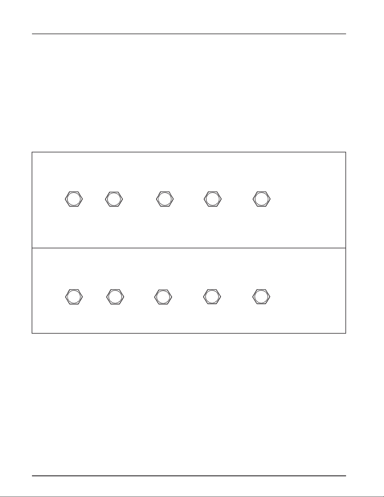
General Torque Values
Metric Fastener T orque Recommendations for S tandard Applications
Tightening Torque: N·m (in. lb.) + or - 10%
Property Class
Noncritical
Fasteners
4.8
Size
M4 1.2 (11) 1.7 (15) 2.9 (26) 4.1 (36) 5.0 (44) 2.0 (18)
M5 2.5 (22) 3.2 (28) 5.8 (51) 8.1 (72) 9.7 (86) 4.0 (35)
M6 4.3 (38) 5.7 (50) 9.9 (88) 14.0 (124) 16.5 (146) 6.8 (60)
M8 10.5 (93) 13.6 (120) 24.4 (216) 33.9 (300) 40.7 (360) 17.0 (150)
5.8
8.8 10.9 12.9
Into Aluminum
Tightening Torque: N·m (ft. lb.) + or - 10%
Property Class
Noncritical
Fasteners
4.8
M10 21.7 (16) 27.1 (20) 47.5 (35) 66.4 (49) 81.4 (60) 33.9 (25)
M12 36.6 (27) 47.5 (35) 82.7 (61) 116.6 (86) 139.7 (103) 61.0 (45)
M14 58.3 (43) 76.4 (55) 131.5 (97) 184.4 (136) 219.7 (162) 94.9 (70)
5.8
8.8
10.9
12.9
Into Aluminum
1.12
Page 15
Safety and General Information
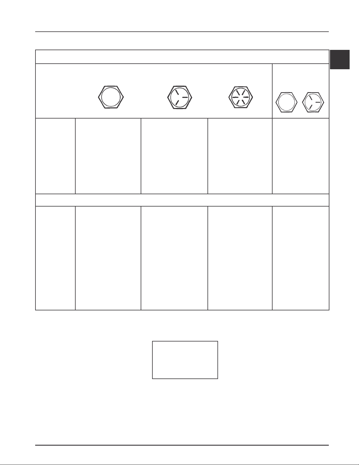
English Fastener T orque Recommendations for St andard Applications
Section 1
Tightening Torque: N·m (in. lb.) + or - 20%
Bolts, Screws, Nuts and Fasteners
Assembled Into Cast Iron or Steel
Grade 2 Grade 5 Grade 8
Size
8-32 2.3 (20) 2.8 (25) --------- 2.3 (20)
10-24 3.6 (32) 4.5 (40) --------- 3.6 (32)
10-32 3.6 (32) 4.5 (40) --------- ---------
1/4-20 7.9 (70) 13.0 (115) 18.7 (165) 7.9 (70)
1/4-28 9.6 (85) 15.8 (140) 22.6 (200) ---------
5/16-18 17.0 (150) 28.3 (250) 39.6 (350) 17.0 (150)
5/16-24 18.7 (165) 30.5 (270) --------- ---------
3/8-16 29.4 (260) --------- --------- ---------
3/8-24 33.9 (300) --------- --------- ---------
Grade 2 or 5
Fasteners Into
Aluminum
Tightening Torque: N·m (ft. lb.) + or - 20%
Size
5/16-24 --------- ---------- 40.7 (30) --------3/8-16 --------- 47.5 (35) 67.8 (50) --------3/8-24 --------- 54.2 (40) 81.4 (60) --------7/16-14 47.5 (35) 74.6 (55) 108.5 (80) --------7/16-20 61.0 (45) 101.7 (75) 142.4 (105) --------1/2-13 67.8 (50) 108.5 (80) 155.9 (115) --------1/2-20 94.9 (70) 142.4 (105) 223.7 (165) --------9/16-12 101.7 (75) 169.5 (125) 237.3 (175) --------9/16-18 135.6 (100) 223.7 (165) 311.9 (230) --------5/8-11 149.2 (110) 244.1 (180) 352.6 (260) --------5/8-18 189.8 (140) 311.9 (230) 447.5 (330) --------3/4-10 199.3 (150) 332.2 (245) 474.6 (350) --------3/4-16 271.2 (200) 440.7 (325) 637.3 (470) ---------
1
Torque
Conversions
N·m = in. lb. x 0.113
N·m = ft. lb. x 1.356
in. lb. = N·m x 8.85
ft. lb. = N·m x 0.737
1.13
Page 16
Section 2
Tools & Aids
Section 2
Tools & Aids
Certain quality tools are designed to help you perform specific disassembly, repair, and reassembly procedures.
By using tools designed for the job, you can properly service engines easier, faster, and safer! In addition, you’ll
increase your service capabilities and customer satisfaction by decreasing engine downtime.
Here is the list of tools and their source.
Separate Tool Suppliers:
Kohler Tools
Contact your source
of supply.
SE Tools
415 Howard St.
Lapeer, MI 48446
Phone 810-664-2981
Toll Free 800-664-2981
Fax 810-664-8181
Design Technology Inc.
768 Burr Oak Drive
Westmont, IL 60559
Phone 630-920-1300
2
IFEtiKecivreS
slooT
noitpircseD .oNtraP/ecruoS
)seireSM&K(looTgnimiTraeGecnalaB
.enignegnilbmessanehwnoitisopdemitnisraegecnalabdlohoT
etalPyalpdnEtfahsmaC
.yalpdnetfahsmacgnikcehcroF
)sigeA(rotcetorPlaeStfahsmaC
.noitallatsnitfahsmacgnirudlaestcetorpoT
retseTnwodkaeLrednilyC
erawtfoScitsongaiD)IFE(noitcejnIleuFcinortcelE
.CPpotkseDropotpaLhtiwesU
.enigneIFEnapugnittesdnagnitoohselbuortroF
elbaliavAstnenopmoClaudividnI
retseTerusserP
thgiLdioN
retpadA°09
sreilPpmalCrekiteO
eriWdeR,gulPedoC
eriWeulB,gulPedoC
S-6055452relhoK
)753-YylremroF(
50428-RLKslooTES
71428-RLKslooTES
.nrowerasevlavro,sgnir,notsip,rednilycfidnanoitneternoitsubmocgnikcehcroF
S-5016752relhoK
S-3216752relhoK
S-1016742relhoK
.cnIygolonhceTngiseD
910-ITD
120-ITD
320-ITD
520-ITD
720-ITD
920-ITD
)seireSSC(looTgnidloHleehwylF 70428-RLKslooTES
relluPleehwylF
.enignemorfleehwylfevomeroT
hcnerWpartSleehwylF
.lavomergnirudleehwylfdlohoT
80428-RLKslooTES
90428-RLKslooTES
2.1
Page 17

Section 2
Tools & Aids
).tnoc(slooT
noitpircseD .oNtraP/ecruoS
looTretfiLevlaVciluardyH
.sretfilciluardyhllatsnidnaevomeroT
retseTmetsySnoitingI
.DCtpecxe,smetsysllanotuptuognitsetroF
.metsysnoitingi)DC(egrahcsideviticapacnotuptuognitsetroF
)seireSM&K(hcnerWtesffO
.stungniniaterlerrabrednilycllatsnierdnaevomeroT
tiKtseTerusserPliO
.erusserplioyfirevdnatsetoT
)tnerructlov021(retseTrotalugeR-reifitceR
)tnerructlov042(retseTrotalugeR-reifitceR
.srotaluger-reifitcertsetotdesU
elbaliavAstnenopmoClaudividnI
ssenraHtseTrotalugeRORP-SC
edoiDhtiwssenraHtseTrotalugeRlaicepS
retseT)MAS(eludoMecnavdAkrapS
KRAPS-TRAMShtiwsenigneno)MASDdnaMASA(MASehttsetoT
.™
)tfihSdioneloS(looTgnidloHhsurBretratS
.gnicivresgnirudsehsurbdlohoT
S-8316752relhoK
S-1055452relhoK
S-2055442relhoK
01428-RLKslooTES
S-6016752relhoK
S-0216752relhoK
S-1416752relhoK
.cnIygolonhceTngiseD
130-ITD
330-ITD
S-0416752relhoK
61428-RLKslooTES
)evirDaitrenI(looTgniRgniniateRretratS
.)sretratsOCSAFgnidulcxe(sgnirgniniaterevirdllatsnierdnaevomeroT
)sretratSllA(tiKgnicivreSretratS
.sehsurbdnasgnirgniniaterevirdllatsnierdnaevomeroT
elbaliavAtnenopmoClaudividnI
)tfihSdioneloS(looTgnidloHhsurBretratS
)evitcudnIlatigiD(retemohcaT
.enignenafo)MPR(deepsgnitarepognikcehcroF
retseTerusserP/muucaV
.retemonamretawaotevitanretlA
)seireSM&K(remaeRediuGevlaV
.noitallatsniretfasediugevlavgnizisroF
S-8116752relhoK
11428-RLKslooTES
61428-RLKslooTES
.cnIygolonhceTngiseD
011-ITD
S-2216752relhoK
31428-RLKslooTES
2.2
Page 18

sdiA
noitpircseD .oNtraP/ecruoS
tnacirbuLtfahsmaC )316ZZrapslaV( S-4175352relhoK
Section 2
Tools & Aids
esaerGcirtceleiD )166GdraugavoN/EG( S-1175352relhoK
2
esaerGcirtceleiD )orP-leF( leS-irbuL
tnacirbuLevirDretratScirtcelE )evirDaitrenI( S-1075325relhoK
tnacirbuLevirDretratScirtcelE )tfihSdioneloS(S-2075325relhoK
®
etitcoL
.resnepsidlosoreazo4niydoByvaeH0095
tnalaeSenociliSVTR
S-7079552relhoK
.esurofdevorppaera,detsilesohtsahcus,stnalaesVTRtnatsiserlio,desab-emixoylnO
®
etitcoL
®
etitcoL
0195
®
etitcoL
®
etitcoL
®
etitcoL
895kcalBartlU
785eulBartlU
reppoCartlU
.scitsiretcarahcgnilaestsebrofdednemmocerera0195ro0095.soN
tnacirbuLevirDenilpS S-2175352relhoK
2.3
Page 19
Section 2
Tools & Aids
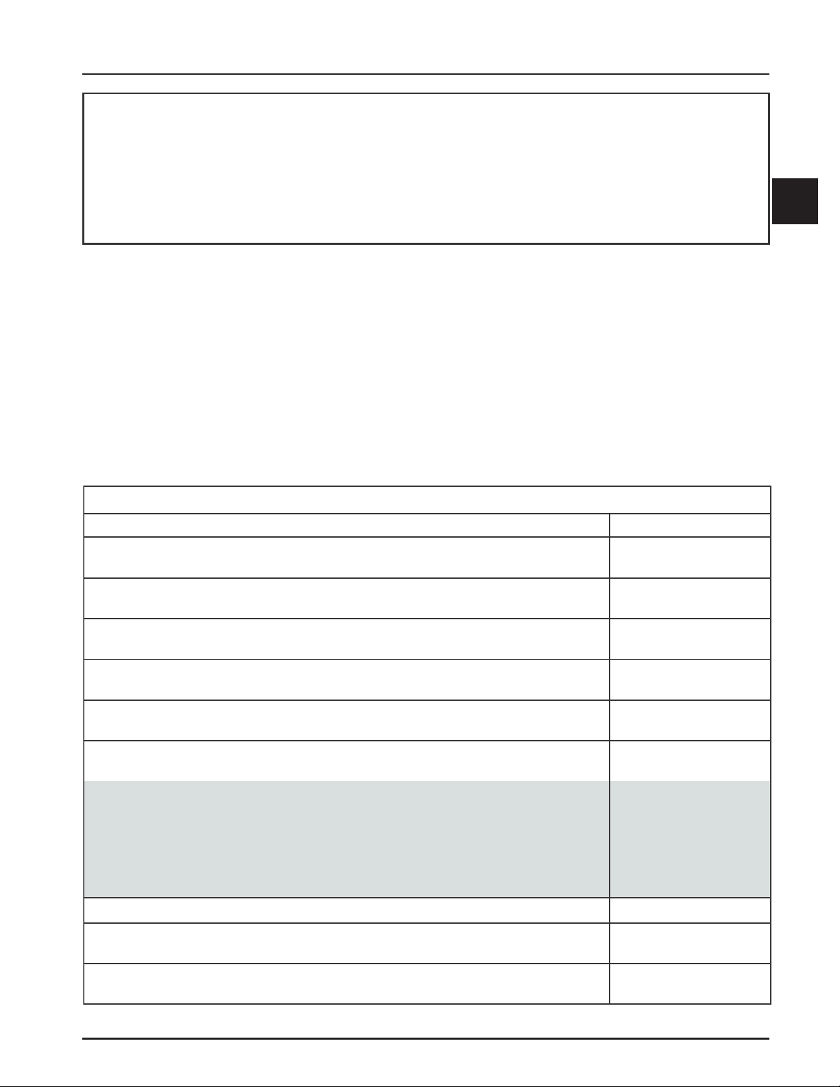
Special Tools You Can Make
Flywheel Holding Tool
A flywheel holding tool can be made out of an old
junk flywheel ring gear as shown in Figure 2-1, and
used in place of a strap wrench.
1. Using an abrasive cut-off wheel, cut out a six
tooth segment of the ring gear as shown.
2. Grind off any burrs or sharp edges.
3. Invert the segment and place it between the
ignition bosses on the crankcase so the tool teeth
engage the flywheel ring gear teeth. The bosses
will lock the tool and flywheel in position for
loosening, tightening, or removing with a puller.
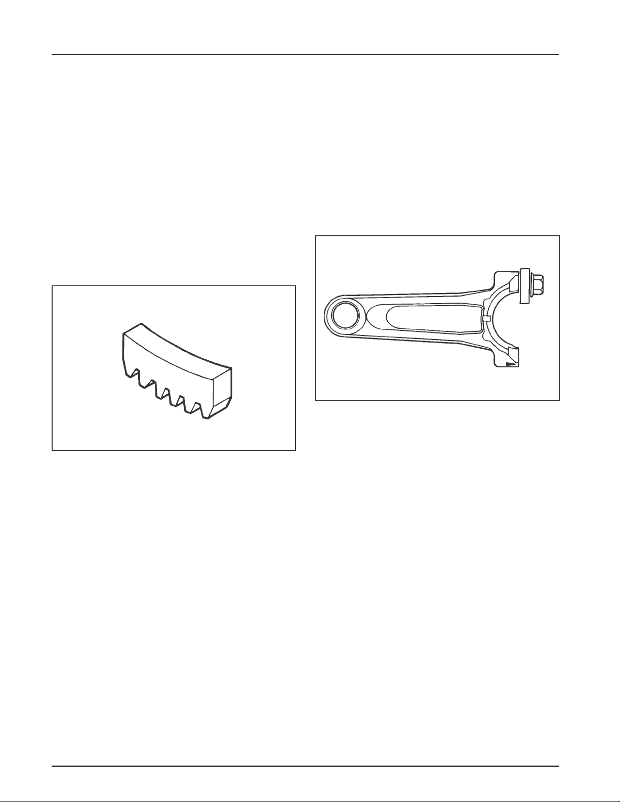
2. Remove the studs of a Posi-Lock rod or grind off
the aligning steps of a Command rod, so the joint
surface is flat.
3. Find a 1 in. long capscrew with the correct
thread size to match the threads in the
connecting rod.
4. Use a flat washer with the correct I.D. to slip on
the capscrew and approximately 1” O.D. (Kohler
Part No. 12 468 05-S). Assemble the capscrew
and washer to the joint surface of the rod, as
shown in Figure 2-2.
Figure 2-1. Flywheel Holding Tool.
Rocker Arm/Crankshaft Tool
A spanner wrench to lift the rocker arms or turn the
crankshaft may be made out of an old junk connecting
rod.
1. Find a used connecting rod from a 10 HP or
larger engine. Remove and discard the rod cap.
Figure 2-2. Rocker Arm/Crankshaf t T ool.
2.4
Page 20

Section 3
Troubleshooting
Section 3
Troubleshooting
Troubleshooting Guide
When troubles occur, be sure to check the simple
causes which, at first, may seem too obvious to be
considered. For example, a starting problem could be
caused by an empty fuel tank.
Some general common causes of engine troubles are
listed below. Use these to locate the causing factors.
Refer to the specific section(s) within this service
manual for more detailed information.
Engine Cranks But Will Not Start
1. Empty fuel tank.
2. Fuel shut-off valve closed.
3. Poor fuel, dirt, or water in the fuel system.
4. Clogged fuel line.
5. Spark plug lead(s) disconnected.
6. Kill switch in off position.
7. Faulty spark plugs.
8. Faulty ignition module(s).
9. Carburetor solenoid malfunction.
10. Battery connected backwards.
11. Safety interlock system engaged.
11. Quality of fuel.
12. Flywheel key sheared.
13. Intake system leak.
Engine Will Not Crank
1. PTO drive is engaged.
2. Battery is discharged.
3. Safety interlock switch is engaged.
4. Loose or faulty wires or connections.
5. Faulty key switch or ignition switch.
6. Faulty electric starter or solenoid.
7. Seized internal engine components.
Engine Runs But Misses
1. Dirt or water in the fuel system.
2. Spark plug lead disconnected.
3. Poor quality of fuel.
4. Faulty spark plug(s).
5. Loose wires or connections that intermittently
ground the ignition kill circuit.
6. Engine overheated.
7. Faulty ignition module or incorrect air gap.
8. Carburetor adjusted incorrectly.
3
Engine Starts But Does Not Keep Running
1. Restricted fuel tank cap vent.
2. Poor fuel, dirt, or water in the fuel system.
3. Faulty or misadjusted choke or throttle controls.
4. Loose wires or connections that short the kill
terminal of ignition module to ground.
5. Faulty cylinder head gasket.
6. Faulty carburetor.
7. Intake system leak.
Engine Starts Hard
1. PTO drive is engaged.
2. Dirt or water in the fuel system.
3. Clogged fuel line.
4. Loose or faulty wires or connections.
5. Faulty or misadjusted choke or throttle controls.
6. Faulty spark plugs.
7. Low compression.
8. Weak spark.
9. Fuel pump malfunction causing lack of fuel.
10. Engine overheated-cooling/air circulation
restricted.
Engine Will Not Idle
1. Dirt or water in the fuel system.
2. Stale fuel and/or gum in carburetor.
3. Faulty spark plugs.
4. Fuel supply inadequate.
5. Idle fuel adjusting needles improperly set.
6. Idle speed adjusting screw improperly set.
7. Low compression.
8. Restricted fuel tank cap vent.
9. Engine overheated-cooling system/air circulation
problem.
Engine Overheats
1. Air intake/grass screen, cooling fins, or cooling
shrouds clogged.
2. Excessive engine load.
3. Low crankcase oil level.
4. High crankcase oil level.
5. Faulty carburetor.
6. Lean fuel mixture.
3.1
Page 21

Section 3
Troubleshooting
Engine Knocks
1. Excessive engine load.
2. Low crankcase oil level.
3. Old or improper fuel.
4. Internal wear or damage.
5. Hydraulic lifter malfunction.
6. Quality of fuel.
7. Incorrect grade of oil.
Engine Loses Power
1. Low crankcase oil level.
2. High crankcase oil level.
3. Dirty air cleaner element.
4. Dirt or water in the fuel system.
5. Excessive engine load.
6. Engine overheated.
7. Faulty spark plugs.
8. Low compression.
9. Exhaust restriction.
10. Low battery.
11. Incorrect governor setting.
Engine Uses Excessive Amount of Oil
1. Incorrect oil viscosity/type.
2. Clogged, broken, or inoperative crankcase
breather.
3. Worn or broken piston rings.
4. Worn cylinder bore.
5. Worn valve stems/valve guides.
6. Crankcase overfilled.
7. Blown head gasket/overheated.
Oil Leaks from Oil Seals, Gaskets
1. Clogged, broken or inoperative crankcase
breather.
2. Loose or improperly torqued fasteners.
3. Piston blowby, or leaky valves.
4. Restricted exhaust.
External Engine Inspection
Before cleaning or disassembling the engine, make a
thorough inspection of its external appearance and
condition. This inspection can give clues to what
might be found inside the engine (and the cause)
when it is disassembled.
• Check for buildup of dirt and debris on the
crankcase, cooling fins, grass screen, and other
external surfaces. Dirt or debris on these areas
are causes of higher operating temperatures and
overheating.
• Check the air cleaner cover and base for damage
or indications of improper fit and seal.
• Check the air cleaner element. Look for holes,
tears, cracked or damaged sealing surfaces, or
other damage that could allow unfiltered air into
the engine. Also note if the element is dirty or
clogged. These could indicate that the engine has
been under serviced.
• Check the carburetor throat for dirt. Dirt in the
throat is further indication that the air cleaner is
not functioning properly.
• Check the oil level. Note if the oil level is within
the operating range on the dipstick, or if it is low
or overfilled.
• Check the condition of the oil. Drain the oil into a
container - the oil should flow freely. Check for
metal chips and other foreign particles.
Sludge is a natural by-product of combustion; a
small accumulation is normal. Excessive sludge
formation could indicate overrich carburetion,
weak ignition, overextended oil change intervals
or wrong weight or type of oil was used, to name
a few.
NOTE: It is good practice to drain oil at a
location away from the workbench. Be
sure to allow ample time for complete
drainage.
Cleaning the Engine
After inspecting the external condition of the engine,
clean the engine thoroughly before disassembling it.
Also clean individual components as the engine is
disassembled. Only clean parts can be accurately
inspected and gauged for wear or damage. There are
many commercially available cleaners that will
quickly remove grease, oil, and grime from engine
parts. When such a cleaner is used, follow the
manufacturer’s instructions and safety precautions carefully.
Make sure all traces of the cleaner are removed before
the engine is reassembled and placed into operation.
Even small amounts of these cleaners can quickly
break down the lubricating properties of engine oil.
• Check for obvious fuel and oil leaks, and
damaged components. Excessive oil leakage can
indicate a clogged or improperly-assembled
breather, worn/damaged seals and gaskets, or
loose or improperly-torqued fasteners.
3.2
Page 22

Section 3
Troubleshooting
Basic Engine Tests
Crankcase Vacuum T est
A partial vacuum should be present in the crankcase
when the engine is operating. Pressure in the
crankcase (normally caused by a clogged or
improperly assembled breather) can cause oil to be
forced out at oil seals, gaskets, or other available
spots.
Crankcase vacuum is best measured with either a
water manometer or a vacuum gauge (see Section 2).
Complete instructions are provided in the kits.
To test the crankcase vacuum with the manometer:
1. Insert the stopper/hose into the oil fill hole. Leave
the other tube of manometer open to atmosphere.
Make sure the shut off clamp is closed.
2. Start the engine and run at no-load high speed
(3200 to 3750 RPM).
3. Open the clamp and note the water level in the
tube.
The level in the engine side should be a minimum
of 10.2 cm (4 in.) above the level in the open side.
If the level in the engine side is less than specified
(low/no vacuum), or the level in the engine side is
lower than the level in the open side (pressure),
check for the conditions in the table below.
4. Close the shut-off clamp before stopping the
engine.
To test the crankcase vacuum with the Vacuum/
Pressure Gauge Kit (see Section 2):
3
1. Remove the dipstick or oil fill plug/cap.
2. Install the adapter into the oil fill/dipstick tube
opening.
3. Push the barbed fitting on the gauge solidly into
the hole in the adapter.
4. Start the engine and bring it up to operating
speed (3200-3600 RPM).
5. Check the reading on the gauge. If the reading is
to the left of 0 on the gauge, vacuum or negative
pressure is indicated. If the reading is to the
right of 0 on the gauge, positive pressure is
present.
Crankcase vacuum should be a minimum of 4
inches of water. If the reading is below the
specification, or if pressure is present, check the
table below for possible causes and remedies.
No Crankcase Vacuum/Pressure in Crankcase
Possible Cause
1. Crankcase breather clogged or inoperative.
2. Seals and/or gaskets leaking. Loose or
improperly torqued fasteners.
3. Piston blow by or leaky valves (confirm by
inspecting components).
4. Restricted exhaust.
Solution
1. Disassemble breather, clean parts thoroughly,
reassemble, and recheck pressure.
2. Replace all worn or damaged seals and gaskets.
Make sure all fasteners are tightened securely. Use
appropriate torque values and sequences when
necessary.
3. Recondition piston, rings, cylinder bore, valves,
and valve guides.
4. Repair/replace restricted muffler/exhaust system.
3.3
Page 23

Section 3
Troubleshooting
Compression T est
A compression test is best performed on a warm
engine. Clean any dirt or debris away from the base
of the spark plugs before removing them. Be sure the
choke is off, and the throttle is wide open during the
test. Compression should be at least 160 psi and
should not vary more than 15% between cylinders.
Cylinder Leakdown T est
A cylinder leakdown test can be a valuable
alternative to a compression test. By pressurizing the
combustion chamber from an external air source, you
can determine if the valves or rings are leaking and
how badly.
The Cylinder Leakdown Tester (see Section 2) is a
relatively simple, inexpensive leakdown tester for
small engines. The tester includes a quick disconnect
for attaching the adapter hose, and a holding tool.
Leakdown T est Instructions
1. Run the engine for 3-5 minutes to warm it up.
2. Remove the spark plug(s) and the air filter from
engine.
3. Rotate the crankshaft until the piston (of
cylinder being tested) is at top dead center (TDC)
of the compression stroke. Hold the engine in this
position while testing. The holding tool supplied
with the tester can be used if the PTO end of the
crankshaft is accessible. Lock the holding tool
onto the crankshaft. Install a 3/8" breaker bar
into the hole/slot of the holding tool, so it is
perpendicular to both the holding tool and
crankshaft PTO.
If the flywheel end is more accessible, use a
breaker bar and socket on the flywheel nut/screw
to hold it in position. An assistant may be needed
to hold the breaker bar during testing. If the
engine is mounted in a piece of equipment, it may
be possible to hold it by clamping or wedging a
driven component. Just be certain that the engine
cannot rotate off of TDC in either direction.
4. Install the adapter into the spark plug hole, but
do not attach it to the tester at this time.
5. Connect an air source of at least 50 psi to the
tester.
6. Turn the regulator knob in the increase direction
(clockwise) until the gauge needle is in the yellow
set area at the low end of the scale.
7. Connect the tester quick-disconnect to the
adapter hose while firmly holding the engine at
TDC. Note the gauge reading and listen for
escaping air at the carburetor intake, exhaust
outlet, and crankcase breather.
8. Check the test results against the following table:
Leakdown Test Results
Air escaping from crankcase breather ......................................................Rings or cylinder worn.
Air escaping from exhaust system ............................................................Defective exhaust valve/improper seating.
Air escaping from carburetor .....................................................................Defective intake valve/improper seating.
Gauge reading in low (green) zone ............................................................ Piston rings and cylinder in good
condition.
Gauge reading in moderate (yellow) zone ...............................................Engine is still usable, but there is some
wear present. Customer should start
planning for overhaul or replacement.
Gauge reading in high (red) zone ...............................................................Rings and/or cylinder have considerable
wear. Engine should be reconditioned or
replaced.
3.4
Page 24
Air Cleaner and Air Intake System
Section 4
Air Cleaner and Air Intake System
Section 4
Air Cleaners
General
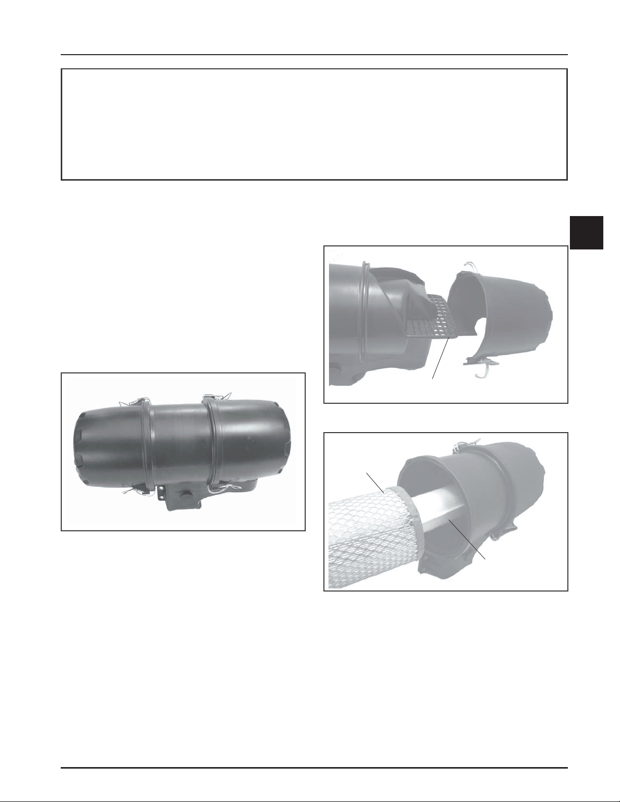
These engines use a heavy-duty style air cleaner as
shown in Figure 4-1, consisting of a cylindrical
housing attached to the carburetor and intake
manifold. The air cleaner housing contains a paper
element and inner element, designed for longer
service intervals. The system is CARB/EPA certified
and the components should not be altered or modified
in any way.
Heavy-Duty Style Air Cleaner
2. Check and clean the screen area on the inlet side.
Pull the air cleaner paper element out of the
housing on opposite side. See Figures 4-2 and 4-3.
4
Inlet Screen
Figure 4-2. Accessing Inlet Screen.
Paper Element
Figure 4-1. Heavy-Duty Style Air Cleaner.
Service
Weekly and every 150 hours: Check filter minder (if
equipped), unhook the two retaining clips on each end
and remove the end caps. Perform inspection of the
paper element and inlet screen area.
Seasonally or every 300 hours of operation (more
often under extremely dusty or dirty conditions),
replace the paper element and check the inner
element. Follow these steps.
1. Unhook the two retaining clips on each end and
remove the end caps from the air cleaner
housing.
Inner
Element
Figure 4-3. Removing Elements.
3. After the paper element is removed, check the
condition of the inner element. It should be
replaced whenever it appears dirty, typically
every other time the paper element is replaced or
every 600 hours. Clean the area around the base
of the inner element before removing it, so dirt
does not get into the engine.
4.1
Page 25
Section 4
Air Cleaner and Air Intake System
4. Do not wash the paper element and inner
element or use compressed air, this will damage
the elements. Replace dirty, bent, or damaged
elements with new genuine Kohler elements as
required. Handle the new elements carefully; do
not use if the sealing surfaces are bent or
damaged.
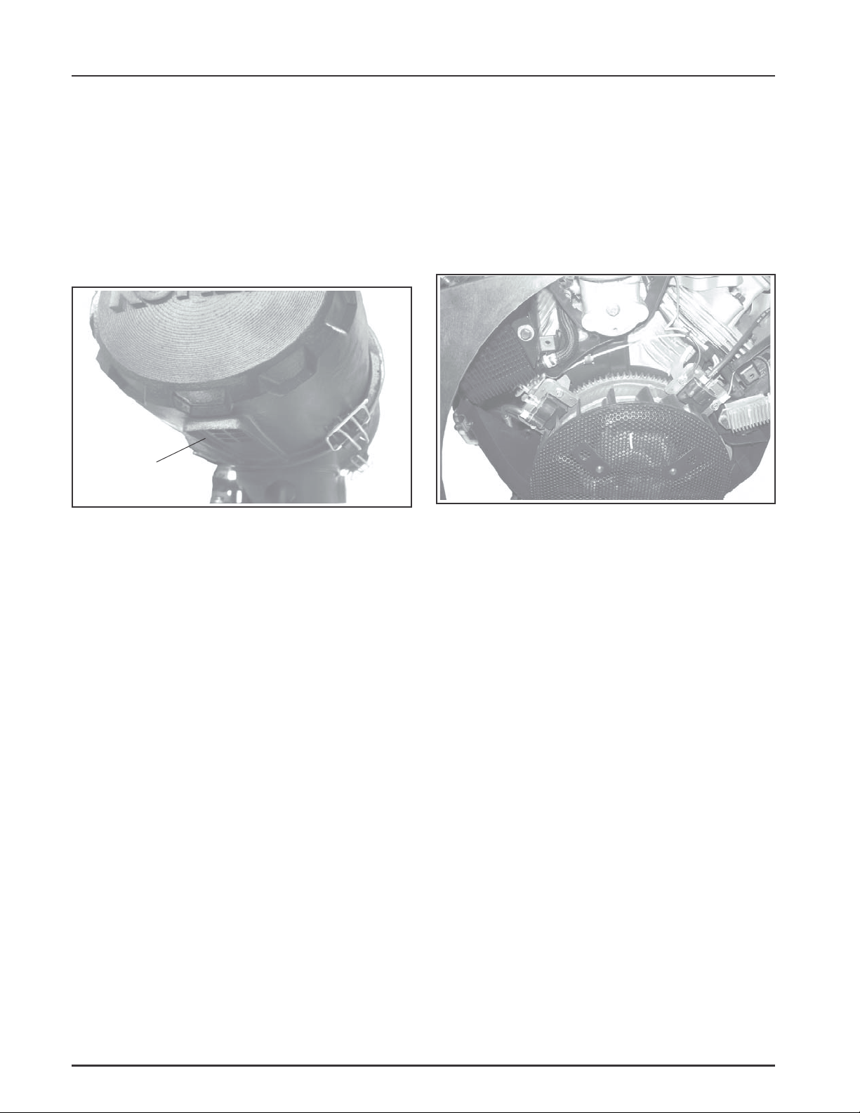
5. Check all parts for wear, cracks, or damage, and
that ejector area is clean. See Figure 4-4. Replace
any damaged components.
Ejector
Area
Air Intake/Cooling System
To ensure proper cooling, make sure the grass screen,
cooling fan fins, and external surfaces of the engine
are kept clean at all times.
Seasonally or every 150 hours of operation (more
often under extremely dusty or dirty conditions),
remove the cylinder shrouds and blower housing.
Clean the cooling fins and external surfaces as
necessary. Make sure all shrouds are reinstalled.
Cylinder
Shroud
Figure 4-4. Ejector Area.
6. Install the new inner element, followed by the
paper element. Slide each fully into place in the
air cleaner housing.
7. Reinstall the end caps and secure with the
retaining clips. See Figure 4-1.
Air Cleaner Components
Whenever the air cleaner cover is removed, or the
paper element or inner element are serviced, check the
following:
Air Cleaner Housing - Make sure the housing is not
damaged or broken and properly secured.
Air Cleaner Inlet - Make sure the air cleaner inlet is
secured tightly to the carburetor and not cracked or
damaged.
Breather Tube - Make sure the tube is attached to the
air cleaner base and the breather cover.
Figure 4-5. Removing Shrouds for Cleaning.
NOTE: Damaged, worn or loose air cleaner
components can allow unfiltered air into the
engine causing premature wear and failure.
Tighten or replace all loose or damaged
components.
4.2
Page 26

Fuel System and Governor
Section 5
Fuel System and Governor
Section 5
Description
This section covers the standard carbureted fuel
system used on these engines. The governor system
used is covered at the end of this section.
WARNING: Explosive Fuel!
Gasoline is extremely flammable and its vapors can explode if
ignited. Store gasoline only in approved containers, in well
ventilated, unoccupied buildings, away from sparks or flames.
Do not fill the fuel tank while the engine is hot or running,
since spilled fuel could ignite if it comes in contact with hot
parts or sparks from ignition. Do not start the engine near
spilled fuel. Never use gasoline as a cleaning agent.
Fuel System Components
The typical carbureted fuel system and related
components include the following:
• Fuel Tank and Valve
• Fuel Lines
• In-line Fuel Filter
• Fuel Pump
• Carburetor
Operation
The fuel from the tank is moved through the in-line
filter and fuel lines by the fuel pump. On engines not
equipped with a fuel pump, the fuel tank outlet is
located above the carburetor inlet allowing gravity to
feed fuel to the carburetor.
Fuel then enters the carburetor float bowl and is
drawn into the carburetor body. There, the fuel is
mixed with air. This fuel-air mixture is then burned
in the engine combustion chamber.
Fuel Recommendations
General Recommendations
Purchase gasoline in small quantities that can be used
within 30 days and store only in clean, approved
containers. Do not use gasoline left over from the
previous season, unless treated with a fuel stabilizer
(see Storage in Section 1), to minimize gum deposits
and ensure easy starting. Do not use gasoline
containing Methanol, or add oil to the gasoline.
Do not overfill the fuel tank. Leave room for the fuel to
expand.
Fuel Type
For best results, use only clean, fresh, unleaded
gasoline with a pump sticker octane rating of 87 or
higher. In countries using the Research fuel rating
method, it should be 90 octane minimum.
Unleaded gasoline is recommended as it leaves less
combustion chamber deposits and reduces harmful
exhaust emissions. Leaded gasoline is not
recommended .
Gasoline/Alcohol blends
Gasohol (up to 10% ethyl alcohol, 90% unleaded
gasoline by volume) is approved as a fuel for Kohler
engines. Other gasoline/alcohol blends including E20
and E85 are not to be used and not approved. Any
failures resulting from use of these fuels will not be
warranted.
Gasoline/Ether blends
Methyl Tertiary Butyl Ether (MTBE) and unleaded
gasoline blends (up to a maximum of 15% MTBE by
volume) are approved as a fuel for Kohler engines.
Other gasoline/ether blends are not approved.
Fuel Filter
Most engines are equipped with an in-line fuel filter.
Periodically inspect the filter and replace with a
genuine Kohler filter seasonally or every 150
operating hours.
Fuel Line
These engines use Low Permeation SAE 30 R7 rated
fuel line; certified to meet emission requirements.
Standard fuel line may not be used. Order
replacement hose by part number through a Kohler
Engine Service Dealer.
5
5.1
Page 27
Section 5
Fuel System and Governor
Fuel System T ests
When the engine starts hard, or turns over but will not start, it is possible that the problem is in the fuel
system. To find out if the fuel system is causing the problem, perform the following tests.
Troubleshooting – Fuel System Related Causes
T e st Conclusion
1. Check the following:
a. Make sure the fuel tank contains clean, fresh,
proper fuel.
b. Make sure the vent in fuel tank cap is open.
c. Make sure the fuel valve is open.
d. Make sure the fuel lines to fuel pump are
secured and in good condition.
2. Check for fuel in the combustion chamber.
a. Disconnect and ground spark plug leads.
b. Close the choke on the carburetor.
c. Crank the engine several times.
d. Remove the spark plug and check for fuel at
the tip.
3. Check for fuel flow from the tank to the fuel pump.
a. Remove the fuel line from the inlet fitting of
the fuel pump.
b. Hold the line below the bottom of the tank.
Open the shut-off valve (if so equipped) and
observe flow.
4. Check the operation of the fuel pump.
a. Remove the fuel line from the inlet fitting of
the carburetor.
b. Crank the engine several times and observe
flow.
2. If there is fuel at the tip of the spark plug, fuel is
reaching the combustion chamber.
If there is no fuel at the tip of the spark plug, check
for fuel flow from the fuel tank (Test 3).
3. If fuel does flow from the line, check for faulty
fuel pump (Test 4).
If fuel does not flow from the line, check the fuel
tank cap vent, fuel pickup screen, in-line filter,
shut-off valve, and fuel line. Correct any
observed problem and reconnect the line.
4. If fuel does flow from the line, check for faulty
carburetor. (Refer to the Carburetor portions of
this section.)
If fuel does not flow from the line, check for a
clogged fuel line. If the fuel line is unobstructed,
check for overfilled crankcase and/or oil in pulse
line. If none of the checks reveal the cause of the
problem, replace the pump.
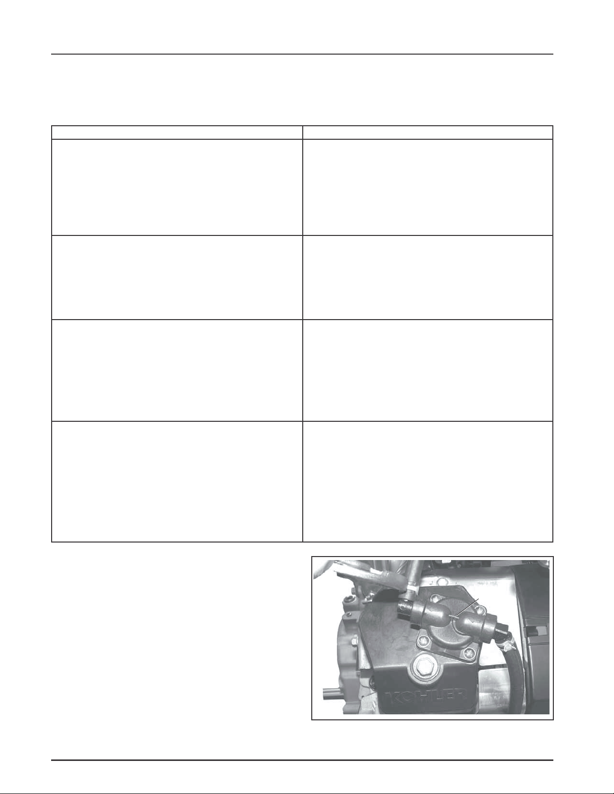
Fuel Pump
General
These engines use either a mechanical fuel pump, or
optional remote-mounted electric fuel pump
assembly. See Figures 5-1 and 5-2. Operation of the
mechanical fuel pump occurs by direct lever/pump
actuation off rocker arm movement. The pumping
action causes the diaphragm on the inside of the
pump to pull fuel in on its downward stroke and to
push it into the carburetor on its upward stroke,
internal check valves prevent fuel from going
backward through the pump.
5.2
Fuel
Pump
Figure 5-1. Mechanical Fuel Pump.
Page 28
Section 5
Fuel System and Governor
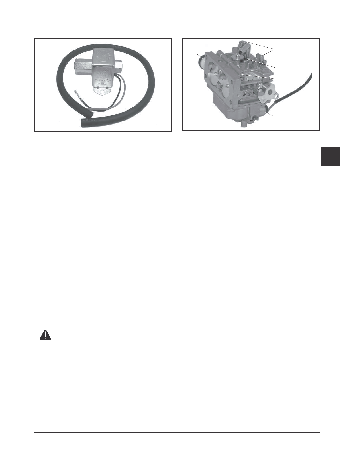
Figure 5-2. Optional Electric Fuel Pump.
Fuel Pump - Replacement
Replacing the Mechanical Fuel Pump
The mechanical fuel pump is an integral part of the
valve cover assembly and not serviced separately. See
Figure 5-1.
1. Disconnect the fuel lines from the inlet and outlet
fittings. Note orientation.
Self-Relieving
Choke
Figure 5-3. Keihin Two-Barrel Carburetor.
Troubleshooting Checklist
When the engine starts hard, runs roughly, or stalls
at low idle speed, check the following areas before
adjusting or disassembling the carburetor.
• Make sure the fuel tank is filled with clean, fresh
gasoline.
• Make sure the fuel tank cap vent is not blocked
and that it is operating properly.
Low Idle Fuel
Adjustments
(With Limiters)
Slow Jets
Bowl Vent
Fuel Shut-Off
Solenoid
5
2. Follow the procedure for replacing the valve
cover (see Sections 8 and 10).
3. Reconnect the fuel lines to the inlet and outlet
fittings and secure with the clamps.
Carburetor
General
Engines in this series are equipped with a Keihin BK
two-barrel, side-draft carburetor with fixed main jets
on a matching intake manifold. The carburetor
features a self-relieving choke, serviceable slow jets,
main jets, bowl drain and a fuel shutdown solenoid.
See Figure 5-3.
WARNING: Explosive Fuel
Gasoline is extremely flammable and its vapors can explode if
ignited. Store gasoline only in approved containers, in well
ventilated, unoccupied buildings, away from sparks or flames.
Do not fill the fuel tank while the engine is hot or running,
since spilled fuel could ignite if it comes in contact with hot
parts or sparks from ignition. Do not start the engine near
spilled fuel. Never use gasoline as a cleaning agent.
• Make sure fuel is reaching the carburetor. This
includes checking the fuel shut-off valve, fuel
tank filter screen, in-line fuel filter, fuel lines and
fuel pump for restrictions or faulty components
as necessary.
• Make sure the air cleaner base and carburetor
are securely fastened to the engine using gaskets
in good condition.
• Make sure the air cleaner element (including
precleaner if equipped) is clean and all air cleaner
components are fastened securely.
• Make sure the ignition system, governor system,
exhaust system, and throttle and choke controls
are operating properly.
If the engine is hard-starting, runs roughly, or stalls
at low idle speed, it may be necessary to adjust or
service the carburetor.
5.3
Page 29
Section 5
Fuel System and Governor
Troubleshooting – Carburetor Related Causes
Condition
1. Engine starts hard, runs roughly,
or stalls at idle speed.
2. Engine runs rich (indicated by
black, sooty exhaust smoke,
misfiring, loss of speed and power,
governor hunting, or excessive
throttle opening).
Possible Cause/Probable Remedy
1. Low idle fuel mixture (some models)/speed improperly adjusted.
Adjust the low idle speed tab, then adjust the low idle fuel needle.
2a. Clogged air cleaner. Clean or replace.
b. Choke partially closed during operation. Check the choke lever/
linkage to ensure choke is operating properly.
c. Low idle fuel mixture is improperly adjusted. Adjust low idle
fuel needle (some models).
d. Float level is set too high. Adjust float according to Float
Replacement Procedure.
e. Dirt under the fuel inlet needle. Remove needle; clean needle and
seat and blow with compressed air.
f. Bowl vent or air bleeds plugged. Remove low idle fuel adjusting
needle. Clean vent, ports, and air bleeds. Blow out all passages
with compressed air.
g. Leaky, cracked or damaged float. Submerge float to check for
leaks.
3. Engine runs lean (indicated by
misfiring, loss of speed and power,
governor hunting, or excessive
throttle opening).
4. Fuel leaks from carburetor. 4a. Float level set too high. See Remedy 2d.
High Altitude Operation
When operating the engine at altitudes of 1500 m
(5000 ft.) and above, the fuel mixture tends to get
over-rich. This can cause conditions such as black,
sooty exhaust smoke, misfiring, loss of speed and
power, poor fuel economy, and poor or slow governor
response.
To compensate for the effects of high altitude, special
high altitude jet kits are available. The kits include
new main jets, slow jets (where applicable), necessary
gaskets, and O-Rings. Refer to the parts manual for
the correct kit number.
3a. Low idle fuel mixture is improperly adjusted. Adjust low idle
fuel needle (some models).
b. Float level is set too low. Adjust float according to Float
Replacement Procedure.
c. Idle holes plugged; dirt in fuel delivery channels. Remove low
idle fuel adjusting needle. Clean main fuel jet and all passages;
blow out with compressed air.
b. Dirt under fuel inlet needle. See Remedy 2e.
c. Bowl vents plugged. Blow out with compressed air.
d. Carburetor bowl gasket leaks. Replace gasket.
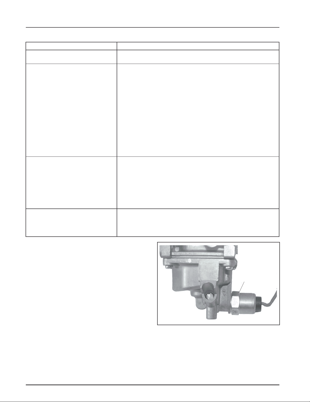
Fuel Shut-Off
Solenoid
Fuel Shut-off Solenoid
Most carburetors are equipped with a fuel shut-off
solenoid. The solenoid is attached to the fuel bowl. See
Figure 5-4. The solenoid has a spring-loaded pin that
retracts when 12 volts is applied to the lead, allowing
fuel flow to the main jets. When current is removed
the pin extends blocking the fuel flow.
5.4
Figure 5-4. Fuel Shut-off Solenoid.
Below is a simple test, made with the engine off, that
can determine if the solenoid is functioning properly:
1. Shut off fuel and remove the solenoid from the
carburetor. When the solenoid is loosened and
removed, gas will leak out of the carburetor.
Page 30

Section 5
Fuel System and Governor
Have a container ready to catch the fuel.
2. Wipe the tip of the solenoid with a shop towel or
blow it off with compressed air, to remove any
remaining fuel. Take the solenoid to a location
with good ventilation and no fuel vapors
present. You will also need a 12 volt power
source that can be switched on and off.
3. Be sure the power source is switched off. Connect
the positive power source lead to the red lead of
the solenoid. Connect the negative power source
lead to the solenoid body.
4. Turn the power source on and observe the pin in
the center of the solenoid. The pin should retract
with the power on and return to its original
position with the power off. Test several times to
verify operation.
Carburetor Details
The Keihin BK two-barrel carburetor is a side-draft
design. The circuits within the carburetor function as
described following:
Float Circuit:
The fuel level in the bowl is maintained by the float
and fuel inlet needle. The buoyant force of the float
stops fuel flow when the engine is at rest. When fuel is
being consumed, the float will drop and fuel pressure
will push the inlet needle away from the seat,
allowing more fuel to enter the bowl. When demand
ceases, the buoyant force of the float will again
overcome the fuel pressure, rising to the
predetermined setting and stop the flow.
Slow & Mid-Range Circuit:
At low speeds the engine operates only on the slow
circuit. As a metered amount of air is drawn through
the slow air bleed jets, fuel is drawn through the two
main jets and further metered through the slow jets.
Air and fuel are mixed in the body of the slow jet and
exit to the transfer port. From the transfer port the air
fuel mixture is delivered to the idle progression
chamber. From the idle progression chamber the air
fuel mixture is metered through the idle port
passages. At low idle when the vacuum signal is
weak, the air/fuel mixture is controlled by the setting
of the idle fuel adjusting screws. This mixture is then
mixed with the main body of air and delivered to the
engine. As the throttle plate opening increases,
greater amounts of air/fuel mixture are drawn in
through the fixed and metered idle progression holes.
As the throttle plate opens further the vacuum signal
becomes great enough so the main circuit begins to
work.
Main (High-Speed) Circuit:
At high speeds/loads the engine operates on the main
circuit. As a metered amount of air is drawn through
the four air jets, fuel is drawn through the main jets.
The air and fuel are mixed in the main nozzles and
then enter the main body of airflow, where further
mixing of the fuel and air occurs. This mixture is then
delivered to the combustion chamber. The carburetor
has a fixed main circuit; no adjustment is possible.
Carburetor Adjustments
Adjustment
NOTE: Carburetor adjustments should be made
only after the engine has warmed up.
The carburetor is designed to deliver the correct fuelto-air mixture to the engine under all operating
conditions. The main fuel jet is calibrated at the
factory and is not adjustable*. The idle fuel adjusting
needles are also set at the factory and normally do not
need adjustment.
*NOTE: Engines operating at altitudes above
approximately 1500 m (5000 ft.) may require
a special high altitude main jet. Refer to High
Altitude Operation later in this section.
If, however, the engine is hard-starting or does not
operate properly, it may be necessary to adjust or
service the carburetor.
Low Idle Speed (RPM) Adjustment
1. Low Idle Speed (RPM) Setting: Place the throttle
control in the idle or slow position. Set the low
idle speed approximately 300 RPM* less than the
intended or specified Governed Idle Speed, by
turning the low idle speed adjusting screw in or
out. Check the speed using a tachometer.
IMPORTANT: The Governed Idle Speed
Adjustment must follow any resetting of the
Low Idle Speed.
*NOTE: The actual low idle speed depends on
the application. Refer to the equipment
manufacturer’s recommendations. The
low idle speed for basic engines is
1200 RPM. To ensure best results when
setting the low idle fuel needle, the low
idle speed should be 1200 RPM (± 75
RPM).
5
5.5
Page 31

Section 5
Fuel System and Governor
Low Idle Fuel Adjusters
(with Limiters)
Low Idle
Bowl
Vent
Figure 5-5. Carburetor Adjustment Locations.
Low Idle Fuel Adjustment
NOTE: Engines will have fixed low idle or limiter
caps on the two idle fuel adjusting needles.
Step 3 can only be performed within the
limits allowed by the cap. Do not attempt to
remove the limiter caps.
1. Start the engine and run at half throttle for 5 to
10 minutes to warm up. The engine must be
warm before doing steps 2, 3, and 4.
2. Place the throttle control into the idle or slow
position. Adjust the low idle speed to 1200 RPM.
Follow the Adjusting the Low Idle Speed (RPM)
procedure.
3. Low Idle Fuel Needle(s) Setting: Place the
throttle into the idle or slow position.
a. Turn one of the low idle fuel adjusting
needles out (counterclockwise) from the
preliminary setting until the engine speed
decreases (rich). Note the position of the
needle. Now turn the adjusting needle in
(clockwise). The engine speed may increase,
then it will decrease as the needle is turned
in (lean). Note the position of the needle. Set
the adjusting needle midway between the
rich and lean settings. See Figure 5-6.
Speed (RPM)
Adjustment
Screw
Adjust to
Midpoint
Rich
Left Side
Figure 5-6. Optimum Low Idle Fuel Settings.
Lean
Adjust to
Midpoint
Rich
Right Side
Lean
Governed Idle System
A governed idle control system is used to maintain a
desired idle speed regardless of ambient conditions
(temperature, parasitic load, etc.) that may change.
An outer secondary spring connected between the
governor lever and the governed idle adjuster on the
main bracket establishes the governed idle speed. See
Figure 5-7.
Governed Idle Speed Adjustment
1. Make sure the governed idle spring is in the outer
hole in the governor lever and the hole in the
governed idle (outer) adjuster. See Figure 5-7.
2. Make sure the governor spring is in the inner slot
of the governor lever and the hole in the high
speed (inner) adjuster. See Figure 5-7. Pull the
governor lever away from carburetor to the limit
of its travel and check that the governor spring is
loose and not under any tension. See Figure 5-8.
Turn the high-speed (RPM) adjustment screw
counter-clockwise (if required) until spring is
loose.
Governor
Spring
b. Repeat the procedure on the other low idle
adjustment needle.
4. Recheck/adjust the Low Idle Speed (RPM) to the
specified setting.
5.6
Governed Idle
Spring
Figure 5-7. Governor Springs Installed.
Page 32

Hold/Pull Governor
Lever Back
Governor Spring Must Be
Loose In Slot
Section 5
Fuel System and Governor
Governed Idle Speed
Adjustment Screw
Figure 5-8. Checking Spring Looseness.
3. Hold the governor lever away from the
carburetor so the throttle lever is against the idle
speed (RPM) adjustment screw of the carburetor.
Start the engine and allow to warm up, then
adjust the screw to set approximately 1200 RPM.
Check using a tachometer. Turn the adjustment
screw (inner) clockwise (in) to increase or
counterclockwise (out) to decrease speed.
4. Release the governor lever and check that the
throttle lever is in the idle (centered) position. See
Figure 5-9. Turn the governed idle (outer)
adjustment screw to obtain the equipment
manufacturer’s recommended idle speed
(1500-1800 RPM). The governed idle speed (RPM)
is typically 300 RPM (approximate) higher than
the low idle speed. See Figure 5-10.
Figure 5-10. Setting Governed Idle Speed RPM
(Air Cleaner Removed For Clarity).
5. Move the throttle lever to the wide-open/full
throttle position and hold in this position. Check
the RPM using a tachometer. Turn the high speed
screw to obtain the intended high speed no-load
RPM. The governed idle speed must be set
before making this adjustment. See Figure 5-11.
High Speed
Adjustment
High Speed(RPM)
Adjustment Screw
Screw
Full Throttle
Position
5
Figure 5-9. Throttle Lever in Idle Position.
Figure 5-11. Setting High Speed RPM (Air Cleaner
Removed for Clarity).
Carburetor Servicing
The following section covers the disassembly, various
servicing procedures, and reassembly of the
carburetor. For each procedure carefully inspect all
components and replace those that are worn or
damaged. The following should also be noted as
service is performed.
• Inspect the carburetor body for cracks, holes,
and other wear or damage.
• Inspect the float for cracks, holes, and missing or
damaged float tabs. Check the float hinge and
shaft for wear or damage.
5.7
Page 33

Section 5
Fuel System and Governor
• Inspect the fuel inlet needle and seat for wear or
damage.
• The choke plate is spring loaded. Check to make
sure it moves freely on the shaft.
NOTE: The main and slow jets are fixed and side
specific and can be removed if required. Fixed
jets for high altitudes are available.
Float Replacement
If symptoms described in the carburetor
troubleshooting guide indicate float level problems,
remove the carburetor from the engine to check and/
or replace the float. Use a float kit to replace the float,
pin, float valve, clip, and screw.
1. Perform the removal procedures for the
appropriate air cleaner and the carburetor
outlined in Section 8 Disassembly.
2. Clean the exterior surfaces of dirt or foreign
material before disassembling the carburetor.
Remove the four mounting screws and carefully
separate the fuel bowl from the carburetor. Do
not damage the fuel bowl O-Rings. Transfer any
remaining fuel into an approved container. Save
all parts. Fuel can also be drained prior to bowl
removal by loosening/removal of the bowl drain
screw. See Figure 5-12.
Float
Inlet
I
Needle
Figure 5-13. Removing Float and Inlet Needle.
5. Attach the inlet needle to the plastic tang of the
float with the wire clip. The formed 90° lip
should point up, with the needle valve hanging
down. See Figure 5-14.
Clip
Inlet
Needle
Fuel Bowl
Bowl Drain Screw
Figure 5-12. Fuel Bowl Removed From Carburetor.
3. Remove the float pin screw and lift out the old
float, pin and inlet needle. See Figure 5-13.
Discard all of the parts. The seat for the inlet
needle is not serviceable, and should not be
removed.
4. Clean the carburetor bowl and inlet seat areas as
required, before installing the new parts.
Float
Figure 5-14. Float and Inlet Needle Details.
6. Install the float and inlet needle down into the
seat and carburetor body. Install the new pivot
pin through the float hinge and secure with the
new retaining screw. See Figure 5-15.
Retaining
Screw
Pivot
Pin
Figure 5-15. Installing Float Assembly.
5.8
Page 34

Section 5
Fuel System and Governor
Figure 5-16. Checking Float Height.
7. Hold the carburetor body so the float assembly
hangs vertically and rests lightly against the fuel
inlet needle. The inlet needle should be fully
seated but the center pin of the needle (on
retainer clip end) should not be depressed. Check
the float height adjustment.
NOTE: The inlet needle center pin is spring
loaded. Make sure the float rests against
the fuel inlet needle without depressing
the center pin.
8. The correct float height setting is 17 mm
(0.669 in.) ± 1.5 mm (0.059 in.), measured from
the float bottom to the body of the carburetor.
See Figure 5-16. Replace the float if the height is
different than specified. DO NOT attempt to
adjust by bending float tab.
NOTE: Be sure to measure from the casting
surface, not the rubber gasket, if still
attached.
Figure 5-17. Installing Fuel Bowl.
10. Install the carburetor and reassemble the engine
as outlined in Section 10 Reassembly.
Disassembly/Overhaul
1. Clean the exterior surfaces of dirt or foreign
material before disassembling the carburetor.
Remove the four mounting screws and separate
the fuel bowl from the carburetor. Transfer any
remaining fuel into an approved container.
Remove and discard the old O-Rings. Fuel can
also be drained prior to bowl removal by
loosening/removal of the bowl drain screw. See
Figure 5-18.
Fuel Bowl
5
9. When the proper float height is obtained,
carefully reinstall the fuel bowl onto the
carburetor, using new O-Rings. Secure with the
four original screws. Torque the screws to
2.5 ± 0.3 N·m (23 ± 2.6 in. lb.). See Figure 5-17.
Bowl Drain Screw
Figure 5-18. Fuel Bowl Removed From Carburetor.
NOTE: Further disassembly of the fuel bowl is
not necessary unless the Fuel Solenoid
Kit, or Fuel Bowl Kit (obtained
separately), will also be installed.
5.9
Page 35

Section 5
Fuel System and Governor
2. Remove the float pin screw and lift out the old
float, pin, and inlet needle. See Figure 5-19.
Discard all the old parts. The seat for the inlet
needle is not serviceable, and should not be
removed.
Float
Inlet
Needle
Figure 5-19. Removing Float and Inlet Needle.
3. Use an appropriate size flat screwdriver, and
carefully remove the two main jets from the
carburetor. Note and mark the jets by location
for proper installation. The main jets may be
size/side specific. After the main jets are
removed, the main nozzles can be removed out
through the bottom of the main towers. Note the
orientation/direction of the nozzles. The end with
the two raised shoulders should be out/down
adjacent to the main jets. Save the parts for
cleaning and reuse. See Figure 5-20.
See Figure 5-21 and 5-22. Save parts for cleaning
and reuse unless a Jet Kit is also being installed.
Clean the slow jets using compressed air. Do not
use wire or carburetor cleaner.
Figure 5-21. Removing Screw and Washer.
Slow (Idle Fuel) Jets
O-Ring
Main Nozzles
Main Jets
Figure 5-20. Main Jets and Nozzles Removed.
4. Remove the screw securing the flat washer and
ground lead (if equipped), from the top of the
carburetor; then carefully pull (lift) out the two
slow jets. The slow jets may be sized/side
specific. Mark or tag the jets for proper
reassembly. Note the small O-Ring on the bottom
of each jet.
5.10
Figure 5-22. Slow Jets and O-Ring Detail.
5. Remove the idle speed (RPM) adjustment screw
and spring from the carburetor. Discard the
parts.
NOTE: The carburetor is now disassembled for
appropriate cleaning and installation of
the parts in the overhaul kit. Further
disassembly is not necessary. The
throttle shaft assembly, fuel inlet seat,
idle fuel adjustment screws with limiter,
and carburetor body, are nonserviceable items and should not be
removed. The choke shaft assembly is
serviceable, however it should not be
removed unless a Choke Repair Kit will
be installed.
Page 36

6. Clean the carburetor body, main jets, vent ports,
seats, etc., using a good commercially available
carburetor solvent. Keep away from plastic or
rubber parts if non-compatible. Use clean, dry
compressed air to blow out the internal channels
and ports. Do not use metal tools or wire to clean
orifices and jets. Inspect and thoroughly check
the carburetor for cracks, wear, or damage.
Inspect the fuel inlet seat for wear or damage.
Check the spring loaded choke plate to make sure
it moves freely on the shaft.
7. Clean the carburetor fuel bowl as required.
Section 5
Fuel System and Governor
Idle Speed
Screw and
Spring
8. Install the two main nozzles into the towers of
the carburetor body. The end of the main nozzles
with the two raised shoulders should be out/
down (adjacent to the main jets). Make sure the
nozzles are completely bottomed. Carefully
install the main jets into the towers of the
carburetor body on the appropriate side, as
identified when removal was performed. See
Figure 5-23.
Nozzle End with
T wo Shoulders
(Out/Down)
Main
Jets
Figure 5-23. Installing Main Nozzles and Main Jets.
9. Make sure the O-Ring near the bottom of each
slow jet is new, or in good condition. Align and
insert the two slow jets into the top of the
carburetor. See Figure 5-22.
Figure 5-24. Installing Idle Speed Adjusting Screw
and Spring.
12. Attach the inlet needle to the plastic tang of the
float with the wire clip. The formed 90° lip
should point up, with the needle valve hanging
down. See Figure 5-25.
Float
Clip
Inlet Needle
Figure 5-25. Float and Inlet Needle Details.
13. Install the float and inlet needle down into the
seat and carburetor body. Install the new pivot
pin through the float hinge and secure with the
new retaining screw. See Figure 5-26.
5
10. Install the large flat retaining washer and secure
with the mounting screw, attaching the ground
lead if originally secured by the screw.
11. Install the new idle speed (RPM) adjustment
screw and spring onto the carburetor. Thread in
until 3 or 4 threads are exposed, as an initial
adjustment. See Figure 5-24.
Figure 5-26. Installing Float Assembly.
5.11
Page 37

Section 5
Fuel System and Governor
14. Hold the carburetor body so the float assembly
hangs vertically and rests lightly against the fuel
inlet needle. The inlet needle should be fully
seated but the center pin of the needle (on
retainer clip end) should not be depressed. Check
the float height adjustment.
NOTE: The inlet needle center pin is spring
loaded. Make sure the float rests against
the fuel inlet needle without depressing
the center pin.
15. The correct float height setting is 17 mm
(0.669 in.) ± 1.5 mm (0.059 in.), measured from
the float bottom to the body of the carburetor.
See Figure 5-27. Replace the float if the height is
different than specified. Do not attempt to adjust
by bending the float tab.
NOTE: Be sure to measure from the casting
surface, not the rubber gasket, if still
attached.
Figure 5-28. Installing Fuel Bowl.
Choke Repair
1. Remove the carburetor from the engine. Discard
the old mounting gaskets for the air cleaner and
carburetor.
2. Clean the areas around the choke shaft and the
self-relieving choke mechanism thoroughly.
Figure 5-27. Checking Float Height.
16. When the proper float height is obtained,
carefully reinstall the fuel bowl, using new
O-Rings onto the carburetor. Secure with the
four original screws. Torque the screws to
2.5 ± 0.3 N·m (23 ± 2.6 in. lb.). See Figure 5-28.
3. Remove and discard the plastic cap from the end
of the choke lever/shaft assembly.
4. Note the position of the spring legs and the choke
plate for correct reassembly later. See Figure
5-29. Remove the two screws attaching the choke
plate to the choke shaft. Pull the shaft out of the
carburetor body, note the preload of spring and
discard the removed parts.
Figure 5-29. Choke Details.
5.12
5. Use a screw extractor (easy-out) and remove the
original choke shaft bushing with the old choke
lever from the carburetor housing. Save the
bushing to use as a driver for installing the new
bushing. Discard the old lever.
6. Clean the I.D. of both choke shaft bores as
required.
Page 38

Section 5
Fuel System and Governor
7. Insert the new bushing through the new choke
lever from the outside, and start the bushing in
the outer shaft bore. Position the choke lever so
the protruding boss on the carburetor housing is
between the two stops formed in the choke lever.
See Figure 5-30.
Stops
Boss
Figure 5-30. Assembling Choke Lever .
8. Turn the old bushing upside down and use it as a
driver to carefully press or tap the new bushing
into the carburetor body until it bottoms. Check
that the choke lever pivots freely without
restriction or binding. See Figure 5-31.
Spring Ends
Choke Shaft
Figure 5-32. Choke Shaft and Spring Details.
10. Slide the choke shaft and spring into the
carburetor. Pivot (preload) the shaft 3/4 turn
counterclockwise with the inner leg of the spring
against the formed stop within the choke lever as
originally assembled. See Figures 5-29 and 5-33.
The outer leg of the spring must still be behind
the formed stop of the choke shaft.
5
Figure 5-31. Installing Bushing.
9. Install the new return spring onto the new choke
shaft, so the outboard leg of the spring is behind
the formed stop on the end of the choke shaft. See
Figure 5-32.
NOTE: Make sure it stays in this location
during the following step.
Figure 5-33. Installing Choke Assembly
Components.
11. Place a drop of Loctite
new screw. Position and install the new choke
plate to the flat side of the choke shaft. Start the
two screws. Close the choke and check the plate
alignment within the carburetor throat, then
tighten the screws securely. Do not overtighten.
See Figure 5-34.
®
on the threads of each
5.13
Page 39

Section 5
Fuel System and Governor
Figure 5-34. Installing Choke Plate.
12. Check for proper operation and free movement of
the parts. Install the new cap.
Always use new gaskets when servicing or
reinstalling carburetors. Repair kits are available
which include new gaskets and other components.
Service/repair kits available for Keihin BK two-barrel
carburetors and affiliated components are:
Carburetor Overhaul Kit
Float Kit
Fuel Solenoid Kit
Bowl Kit
High Altitude Kit (1525-3048 m/5,000-10,000 ft.)
High Altitude Kit (Over 3048 m/10,000 ft.)
5.14
Page 40

Section 5
Fuel System and Governor
5
1. Carburetor Body Subassembly
2. Idle Speed Screw
3. Idle Speed Spring
4. Screw
5. Ground Lead
6. Retaining Washer
7. Slow Jet - RH Side
8. Slow Jet - LH Side
9. O-Ring (Slow Jet) (2)
10. Fuel Bowl
11. O-Ring (Fuel Bowl - Upper)
Figure 5-35. Keihin BK Two-Barrel Carburetor - Exploded View.
Governor
General
The governor is designed to hold the engine speed
constant under changing load conditions. Most
engines are equipped with a centrifugal flyweight
mechanical governor. The governor gear/flyweight
mechanism of the mechanical governor is mounted
inside the crankcase and is driven off the gear on the
camshaft. This governor design works as follows:
12. O-Ring (Fuel Bowl - Lower)
13. Drain Screw
14. Bowl Screw (4)
15. Fuel Solenoid
16. Sealing Washer
17. Float
18. Pin
19. Screw
20. Float Clip
21. Float Valve/Inlet Needle
22. Main Nozzle - Right Side
• Centrifugal force acting on the rotating governor
gear assembly causes the flyweights to move
outward as speed increases. Governor spring
tension moves them inward as speed decreases.
• As the flyweights move outward, they cause the
regulating pin to move outward.
• The regulating pin contacts the tab on the cross
shaft causing the shaft to rotate.
23. Main Nozzle - Left Side
24. Main Jet - Right Side
25. Main Jet - Left Side
26. Choke Dust Cap
27. Choke Shaft
28. Spring
29. Bushing
30. Choke Lever
31. Choke Plate
32. Choke Plate Screw (2)
5.15
Page 41

Section 5
Fuel System and Governor
• One end of the cross shaft protrudes through the
crankcase. The rotating action of the cross shaft
is transmitted to the throttle lever of the
carburetor through the external throttle linkage.
See Figure 5-36.
Governor
Lever
Governor
Spring
Governed
Idle Spring
Cross Shaft
Figure 5-36. Governor Linkage (Air Cleaner
Removed for Clarity).
• When the engine is at rest, and the throttle is in
the fast position, the tension of the governor
spring holds the throttle plate open. When the
engine is operating, the governor gear assembly
is rotating. The force applied by the regulating
pin against the cross shaft tends to close the
throttle plate. The governor spring tension and
the force applied by the regulating pin balance
each other during operation, to maintain engine
speed.
Initial Adjustment Procedure
Make this adjustment whenever the governor arm is
loosened or removed from the cross shaft. See Figure
5-36 and adjust as follows:
1. Make sure the throttle linkage is connected to the
governor arm and the throttle lever on the
carburetor.
2. Loosen the hex nut holding the governor lever to
the cross shaft.
3. Move the governor lever toward the carburetor
as far as it will go (wide open throttle) and hold
in this position.
4. Insert a long thin rod or tool into the hole on the
cross shaft and rotate the shaft clockwise
(viewed from the end) as far as it will turn, then
torque the hex nut to 7.3 N·m (65 in. lb.).
High Speed (RPM) Adjustment
1. With the engine running, move the throttle
control to fast. Use a tachometer to check the
RPM speed.
2. Turn the inner adjustment screw outward to
decrease, or inward to increase the RPM speed.
Check RPM with a tachometer.
3. Stop when the desired RPM speed is obtained.
• When load is applied and the engine speed and
governor gear speed decreases, the governor
spring tension moves the governor arm to open
the throttle plate wider. This allows more fuel
into the engine, increasing the engine speed. As
the speed reaches the governed setting, the
governor spring tension and the force applied by
the regulating pin will again offset each other to
hold a steady engine speed.
Adjustments
NOTE: Do not tamper with the governor setting.
Overspeed is hazardous and could cause
personal injury.
General
The governed speed setting is determined by the
position of the throttle control. It can be variable or
constant, depending on the engine application.
High Speed (RPM)
Adjustment Screw
Figure 5-37. High Speed RPM Adjustment (Air
Cleaner Removed For Clarity.
5.16
Page 42

Section 6
Lubrication System
Section 6
Lubrication System
General
This engine uses a full pressure lubrication system.
This system delivers oil under pressure to the
crankshaft, camshaft, and connecting rod bearing
surfaces. In addition to lubricating the bearing
surfaces, the lubrication system supplies oil to the
hydraulic valve lifters.
A high-efficiency gerotor pump is located in the
closure plate. The oil pump maintains high oil flow
and oil pressure, even at low speeds and high
operating temperatures. A pressure relief valve limits
the maximum pressure of the system.
Service
The closure plate must be removed to service the oil
pickup, the pressure relief valve, and the oil pump.
Refer to the appropriate procedures in Sections 8, 9,
and 10.
Oil Recommendations
Using the proper type and weight of oil in the
crankcase is extremely important. So is checking oil
daily and changing oil regularly. It is also
recommended that a consistent brand of oil be used.
Failure to use the correct oil, or using dirty oil, causes
premature engine wear and failure.
NOTE: Using other than service class SG, SH, SJ or
higher oil, or extending oil change intervals
longer than recommended can cause engine
damage.
NOTE: Synthetic oils meeting the listed
classifications may be used with oil changes
performed at the recommended intervals.
However, to allow piston rings to properly
seat, a new or rebuilt engine should be
operated for at least 50 hours using standard
petroleum based oil before switching to
synthetic oil.
A logo or symbol on oil containers identifies the API
service class and SAE viscosity grade. See Figure 6-1.
6
Use high-quality detergent oil of API (American
Petroleum Institute) service class SG, SH, SJ or
higher. Select the viscosity based on the air
temperature at the time of operation as shown in the
following table.
RECOMMENDED SAE VISCOSITY GRADES
10W-30
**
5W-20, 5W-30
°F -20 0 20 32 40 60 80 100
°C -30 -20 -10 0 10 20 30 40
TEMPERATURE RANGE EXPECTED BEFORE NEXT OIL CHANGE
* Use of synthetic oil having 5W-20 or 5W-30 rating is acceptable,
up to 4°C (40°F)
** Synthetic oils will provide better starting in extreme cold below
23°C (-10°F)
*
Kohler 10W-30
Figure 6-1. Oil Container Logo.
The top portion of the symbol shows service class
such as API SERVICE CLASS SJ. The symbol may
show additional categories such as SH, SG/CC, or
CD. The center portion shows the viscosity grade
such as SAE 10W-30. If the bottom portion shows
Energy Conserving, it means that oil is intended to
improve fuel economy in passenger car engines.
6.1
Page 43

Section 6
Lubrication System
Checking Oil Level
The importance of checking and maintaining the
proper oil level in the crankcase cannot be
overemphasized. Check oil BEFORE EACH USE as
follows:
1. Make sure the engine is stopped, level, and is cool
so the oil has had time to drain into the sump.
2. Clean the area around the dipstick before
removing it. This will help to keep dirt, grass
clippings, etc., out of the engine.
3. Remove the dipstick; wipe oil off. Reinsert the
dipstick into the tube until fully seated. See
Figure 6-2.
Oil Fill Cap
Dipstick
NOTE: To prevent extensive engine wear or damage,
always maintain the proper oil level in the
crankcase. Never operate the engine with the
oil level below the ‘‘L” mark or above the ‘‘F”
mark on the dipstick.
Changing Oil and Oil Filter
Changing Oil
Change oil seasonally or every 150 hours of operation,
(more frequently under severe conditions). Refill with
service class SG, SH, SJ, or higher oil as specified in the
Viscosity Grades table on page 6.1.
Change the oil while the engine is still warm. The oil
will flow more freely and carry away more
impurities. Make sure the engine is level when filling
or checking oil.
Change the oil as follows:
1. Clean the areas around one of the drain plugs, oil
fill cap, and dipstick.
2. Remove one of the oil drain plugs, oil fill cap, and
dipstick. Be sure to allow ample time for
complete drainage.
Figure 6-2. Dipstick and Oil Fill Cap Locations
4. Remove dipstick and check oil level. The level
should be between the ‘‘F’’ and ‘‘L’’ marks. If low,
remove the oil fill cap and add oil of the proper
type up to the “F” mark. Reinstall oil fill cap and
dipstick.
Operating
Range
Figure 6-3. Oil Level Marks on Dipstick.
Oil Drain Plug
Figure 6-4. Oil Drain Plug (Starter Side).
Oil Drain Plug
6.2
Figure 6-5. Oil Drain Plug (No. 2 Side).
Page 44

3. Reinstall the drain plug and torque to 21.4 N·m
(15.7 ft. lb.).
4. Fill the crankcase, with new oil of the proper
type, to the “F” mark on the dipstick. Refer to Oil
Type on page 6.1. Always check the level with the
dipstick before adding more oil.
Oil Fill Cap
Figure 6-6. Removing Oil Fill Cap.
5. Reinstall the oil fill cap and tighten securely.
Reinstall dipstick.
Section 6
Lubrication System
Figure 6-8. Optional Remote Mounted Oil Filter.
Replace the oil filter as follows:
1. Before removing the oil filter, clean the area
around the oil filter and housing to keep dirt and
debris out of the engine. Remove the old filter. On
crankcase mounted oil filter housings, a spring
loaded inner cup allows automatic oil drainback
into the crankcase as the oil filter is removed.
Wipe off the surface where the oil filter mounts.
2. Drain the oil from the engine crankcase.
6
Changing Oil Filter
Replace the oil filter seasonally (150 hours), or at least
every other oil change (every 300 hours of operation).
Always use a genuine Kohler oil filter. The oil filter on
most engines is located on top of the crankcase
between the cylinders. Some models use a remote
mounted oil filter. See Figures 6-7 and 6-8.
Oil Filter
Figure 6-7. Engine Mounted Oil Filter.
3. Allow ample time for the oil to drain from the
crankcase.
4. Reinstall the drain plug and torque to 21.4 N·m
(15.7 ft. lb.).
5. Apply a thin film of clean oil to the rubber gasket
on the new filter. Partial prefilling of the oil filter
is recommended.
6. Install the replacement oil filter to the filter
adapter or oil cooler. Turn the oil filter clockwise
until the rubber gasket contacts the oil filter
housing (not inner cup), then tighten the filter an
additional 3/4-1 turn.
7. Fill the crankcase with new oil of the proper type
to the “F” mark on the dipstick.
8. Start the engine and check for oil leaks. Correct
any leaks before placing the engine into service.
Check oil level to be sure it is up to but not over
the “F” mark.
6.3
Page 45

Section 6
Lubrication System
Service Oil Cooler
These engines are equipped with an oil cooler
mounted under the No. 2 side cylinder shroud,
separate from the oil filter. See Figure 6-9.
Oil
Cylinder
Shroud
Figure 6-9. Oil Cooler.
Inspect and clean the oil cooler every 150 hours of
operation (more frequently under severe conditions).
In order to be effective, the oil cooler must be kept free
of debris.
To service the oil cooler, clean the outside of fins with
a brush, vacuum, or compressed air. If required,
remove the two screws holding the cooler unit to the
backing shroud asseembly. Carefully pull the cooler
outward and clean the underside. After cleaning,
reinstall the oil cooler to the backing shroud with the
two mounting screws.
Cooler
Oil
Cooler
Figure 6-11. Cleaning Underside of Oil Cooler.
Oil Sentry™
General
Some engines are equipped with an optional Oil
Sentry™ oil pressure monitor switch. See Figure 6-12.
If the oil pressure drops below an acceptable level, the
Oil Sentry™ will either shut off the engine or activate
a warning signal, depending on the application.
The pressure switch is designed to break contact as
the oil pressure increases above 7-11 psi, and make
contact as the oil pressure decreases below 7-11 psi.
On stationary or unattended applications (pumps,
generators, etc.), the pressure switch can be used to
ground the ignition module to stop the engine. On
vehicular applications (lawn tractors, mowers, etc.)
the pressure switch can only be used to activate a low
oil warning light or signal.
Figure 6-10. Cleaning Top of Oil Cooler.
6.4
NOTE: Make sure the oil level is checked before each
use and is maintained up to the “F” mark on
the dipstick. This includes engines equipped
with Oil Sentry™ .
Pressure Switch
Figure 6-12. Oil Sentry™ Pressure Switch.
Page 46

Section 6
Lubrication System
Installation
The Oil Sentry™ pressure switch is installed in the
closure plate pressure port. See Figure 6-12. On
engines not equipped with Oil Sentry™ the
installation hole is sealed with a 1/8-27 N.P.T.F. pipe
plug.
To install the switch, follow these steps:
1. Apply pipe sealant with Teflon® (Loctite® No.
59241 or equivalent) to the threads of the switch.
2. Install the switch into the tapped hole in the
closure plate. See Figure 6-12.
3. Torque the switch to 10.1 N·m (90 in. lb.).
T esting
Compressed air, a pressure regulator, pressure gauge,
and a continuity tester are required to test the switch.
1. Connect the continuity tester across the blade
terminal and the metal case of the switch. With
0 psi pressure applied to the switch, the tester
should indicate continuity (switch closed).
2. Gradually increase the pressure to the switch. As
the pressure increases through the range of
7-11 psi the tester should indicate a change to no
continuity (switch open). The switch should
remain open as the pressure is increased to 90 psi
maximum.
3. Gradually decrease the pressure through the
range of 7-11 psi. The tester should indicate a
change to continuity (switch closed) down to
0 psi.
4. Replace the switch if it does not operate as
specified.
6
6.5
Page 47

Section 7
Electrical System and Components
Section 7
Electrical System and Components
This section covers the operation, service, and repair
of the electrical system components. Systems and
components covered in this section are:
• Spark Plugs
• Battery and Charging System
• Electric Starter
Spark Plugs
Engine misfire or starting problems are often caused
by a spark plug that has improper gap or is in poor
condition.
The engine is equipped with the following spark
plugs:
Type: The standard spark plug is a Champion
XC10YC (Kohler Part No. 62 132 04-S).
Equivalent alternate brand plugs can also be
used.
Gap: 0.76 mm (0.030 in.)
Thread Size: 14 mm
Reach: 19.1 mm (3/4 in.)
Hex Size: 15.9 mm (5/8 in.)
Spark Plug Service
Every 200 hours of operation, remove each spark
plug. Check its condition and either reset the gap or
replace with a new plug as necessary. Replace spark
plugs every 600 hours. To service the plugs, perform
the following steps:
®
3. Check the gap using a wire feeler gauge. Adjust
the gap to 0.76 mm (0.030 in.) by carefully
bending the ground electrode. See Figure 7-1.
Wire Gauge
Spark Plug
Ground
Electrode
Figure 7-1. Servicing Spark Plug.
4. Reinstall the spark plug into the cylinder head
and torque to 24.4-29.8 N·m (18-22 ft. lb.).
Inspection
Inspect each spark plug as it is removed from the
cylinder head. The deposits on the tip are an
indication of the general condition of the piston rings,
valves, and carburetor.
0.76 mm
(0.030 in.) Gap
7
1. Before removing each spark plug, clean the area
around the base of the plug to keep dirt and
debris out of the engine.
2. Remove the plug and check its condition. See
Inspection following this procedure. Replace the
plug if necessary.
NOTE: Do not clean spark plug in a machine
using abrasive grit. Some grit could
remain in the spark plug and enter the
engine causing extensive wear and
damage.
Normal and fouled plugs are shown in the following
photos:
7.1
Page 48

Section 7
Electrical System and Components
Normal: A plug taken from an engine operating under
normal conditions will have light tan or gray colored
deposits. If the center electrode is not worn, a plug in
this condition could be set to the proper gap and
reused.
Carbon Fouled: Soft, sooty, black deposits indicate
incomplete combustion caused by a restricted air
cleaner, over rich carburetion, weak ignition, or poor
compression.
Wet Fouled: A wet plug is caused by excess fuel or oil
in the combustion chamber. Excess fuel could be
caused by a restricted air cleaner, a carburetor
problem, or operating the engine with too much
choke. Oil in the combustion chamber is usually
caused by a restricted air cleaner, a breather
problem, worn piston rings, or valve guides.
Overheated: Chalky, white deposits indicate very
high combustion temperatures. This condition is
usually accompanied by excessive gap erosion. Lean
carburetor settings, an intake air leak, or incorrect
spark timing are normal causes for high combustion
temperatures.
Worn: On a worn plug, the center electrode will be
rounded and the gap will be greater than the specified
gap. Replace a worn spark plug immediately.
7.2
Page 49

Section 7
Electrical System and Components
Battery
General
A 12-volt battery with 400 cold cranking amps (cca) is
generally recommended for starting in all conditions.
A smaller capacity battery is often sufficient if an
application is started only in warmer temperatures.
Refer to the following table for minimum capacities
based on anticipated ambient temperatures. The
actual cold cranking requirement depends on engine
size, application, and starting temperatures. The
cranking requirements increase as temperatures
decrease and battery capacity shrinks. Refer also to
the operating instructions of the equipment this
engine powers for specific battery requirements.
Battery Size Recommendations
2. Keep the cables, terminals, and external surfaces
of the battery clean. A build-up of corrosive acid
or grime on the external surfaces can cause the
battery to self-discharge. Self-discharge occurs
rapidly when moisture is present.
3. Wash the cables, terminals, and external surfaces
with a mild baking soda and water solution.
Rinse thoroughly with clear water.
NOTE: Do not allow the baking soda solution to
enter the cells as this will destroy the
electrolyte.
Battery Test
To test the battery, you will need a DC voltmeter.
Perform the following steps (See Figure 7-2):
1. Connect the voltmeter across the battery
terminals.
2. Crank the engine. If the battery drops below 9
volts while cranking, the battery is too small,
discharged, or faulty.
If the battery charge is insufficient to turn over the
engine, recharge the battery.
Battery Maintenance
Regular maintenance is necessary to prolong battery
life.
WARNING: Explosive Gas!
Batteries produce explosive hydrogen gas while being charged.
To prevent a fire or explosion, charge batteries only in well
ventilated areas. Keep sources of ignition away from the
battery at all times. Keep batteries out of the reach of children.
Remove all jewelry when servicing batteries.
Before disconnecting the negative (-) ground cable, make sure
all switches are OFF. If ON, a spark will occur at the ground
cable terminal which could cause an explosion if hydrogen gas
or gasoline vapors are present.
1. Regularly check the level of electrolyte. Add
distilled water as necessary to maintain the
recommended level.
NOTE: Do not overfill the battery. Poor
performance or early failure due to loss
of electrolyte will result.
DC V oltmeter
7
Battery
Figure 7-2. Battery V oltage T est.
7.3
Page 50

Section 7
Electrical System and Components
Electronic CD Ignition System
Kill Switch or
‘‘Off’’ Position of
Key Switch
(0.28/0.33 mm)
0.011/0.013 in. Air Gap
Figure 7-3. Capacitive Discharge (Fixed Timing) Ignition System.
Operation of CD Ignition System
Capacitive Discharge with Fixed Timing
This system (Figure 7-3) consists of the following
components:
• A magnet assembly which is permanently
affixed to the flywheel.
• Two electronic capacitive-discharge ignition
modules (Figure 7-3) which mount on the engine
crankcase .
• A kill switch (or key switch) which grounds the
modules to stop the engine.
• Two spark plugs.
The timing of the spark is controlled by the location of
the flywheel magnet group as referenced to engine top
dead center.
Ignition
Modules
Spark Plug
Magnet
Flywheel
D1
SCS
L1
L2
Figure 7-4. Capacitive Discharge Ignition Module Schematic.
Operation: As the flywheel rotates, the magnet
grouping passes the input coil (L1). The
corresponding magnetic field induces energy into the
input coil (L1). The resultant pulse is rectified by D1
and charges capacitor C1. As the magnet assembly
completes its pass, it activates the triggering device
(L2), which causes the semiconductor switch (SCS) to
turn on. With the device switch ON, the charging
capacitor (C1) is directly connected across the
primary (P) of the output transformer (T1). As the
capacitor discharges, the current initiates a fast rising
flux field in the transformer core. A high voltage pulse
is generated from this action into the secondary
winding of the transformer. This pulse is delivered to
the spark plug gap. Ionization of the gap occurs,
resulting in an arc at the plug electrodes. This spark
ignites the fuel-air mixture in the combustion
chamber.
C1
Troubleshooting CD Ignition Systems
The CD ignition systems are designed to be trouble
free for the life of the engine. Other than periodically
checking/replacing the spark plugs, no maintenance
or timing adjustments are necessary or possible.
Mechanical systems do occasionally fail or break
down however, so the following troubleshooting
information is provided to help you get to the root of
a reported problem.
The CD ignition systems produce a high-energy electric spark,
but the spark must be discharged, or damage to the system can
result. Do not crank or run an engine with a spark plug lead
disconnected. Always provide a path for the spark to discharge
to ground.
T1
Spark Plug
P
CAUTION: High-Energy Electric Spark!
S
7.4
Page 51

Section 7
Electrical System and Components
Reported ignition problems are most often due to
poor connections. Before beginning the test procedure,
check all external wiring. Be certain all ignitionrelated wires are connected, including the spark plug
leads. Be certain all terminal connections fit snugly.
Make sure the ignition switch is in the run position.
NOTE: The CD ignition systems are sensitive to
excessive load on the kill lead. If a customer
complains of hard starting, low power, or
misfire under load, it may be due to excessive
draw on the kill circuit. Perform the
appropriate test procedure.
Test Procedure for Standard (Fixed Timing) CD
Ignition System
Isolate and verify the trouble is within the engine
ignition system.
1. Locate the plug connectors where the wiring
harnesses from the engine and equipment are
joined. Separate the connectors and remove the
white kill lead from the engine connector. Rejoin
the connectors and position or insulate the kill
lead terminal so it cannot touch ground. Try to
start** the engine to verify whether the reported
problem is still present.
a. If the problem is gone, the electrical
system on the unit is suspect. Check the
key switch, wires, connections, safety
interlocks, etc.
2. Test for spark on both cylinders with Kohler
ignition tester (see Section 2). Disconnect one
spark plug lead and connect it to the post
terminal of the tester. Connect the clip to a good
ground, not to the spark plug. Crank the engine
and observe the tester spark gap. Repeat the
procedure on the other cylinder. Remember to
reconnect the first spark plug lead.
a. If one side is not firing, check all wiring,
connections, and terminations on that side. If
wiring is okay, replace ignition module and
retest for spark.
b. If the tester shows spark, but the engine
misses or won’t run on that cylinder, try a
new spark plug.
c. If neither side is firing, recheck position of
ignition switch and check for shorted kill
lead.
Battery Charging System
General
Most engines are equipped with a 15, 20, or 25 amp
regulated charging system. See Figures 7-5, 7-6, 7-7,
and 7-8.
NOTE: Observe the following guidelines to avoid
damage to the electrical system and
components:
7
b. If the problem persists, the condition is
associated with the ignition or electrical
system of the engine. Leave the kill lead
isolated until all testing is completed.
**NOTE: If the engine starts or runs during any of the
testing, you may need to ground the kill lead
to shut it down. Because you have
interrupted the kill circuit, it may not stop
using the switch.
• Make sure the battery polarity is correct. A
negative (-) ground system is used.
• Disconnect the rectifier-regulator plug and/or the
wiring harness plug before doing any electric
welding on the equipment powered by the
engine. Also, disconnect all other electrical
accessories in common ground with the engine.
• Prevent the stator (AC) leads from touching or
shorting while the engine is running. This could
damage the stator.
7.5
Page 52

Section 7
Electrical System and Components
15/20/25 Amp Regulated Charging System
Figure 7-5. 25 Amp Stator and 20/25 AmpRectifierRegulator.
NOTE: 20 amp charging systems use a 15 amp stator with a 25 amp rectifier-regulator.
Figure 7-6. 15 Amp St ator and Rectifier-Regulator.
Figure 7-7. Wiring Diagram-15/20/25 Amp Regulated Battery Charging System with Fixed Timing, Four
Pin Connector.
7.6
Page 53
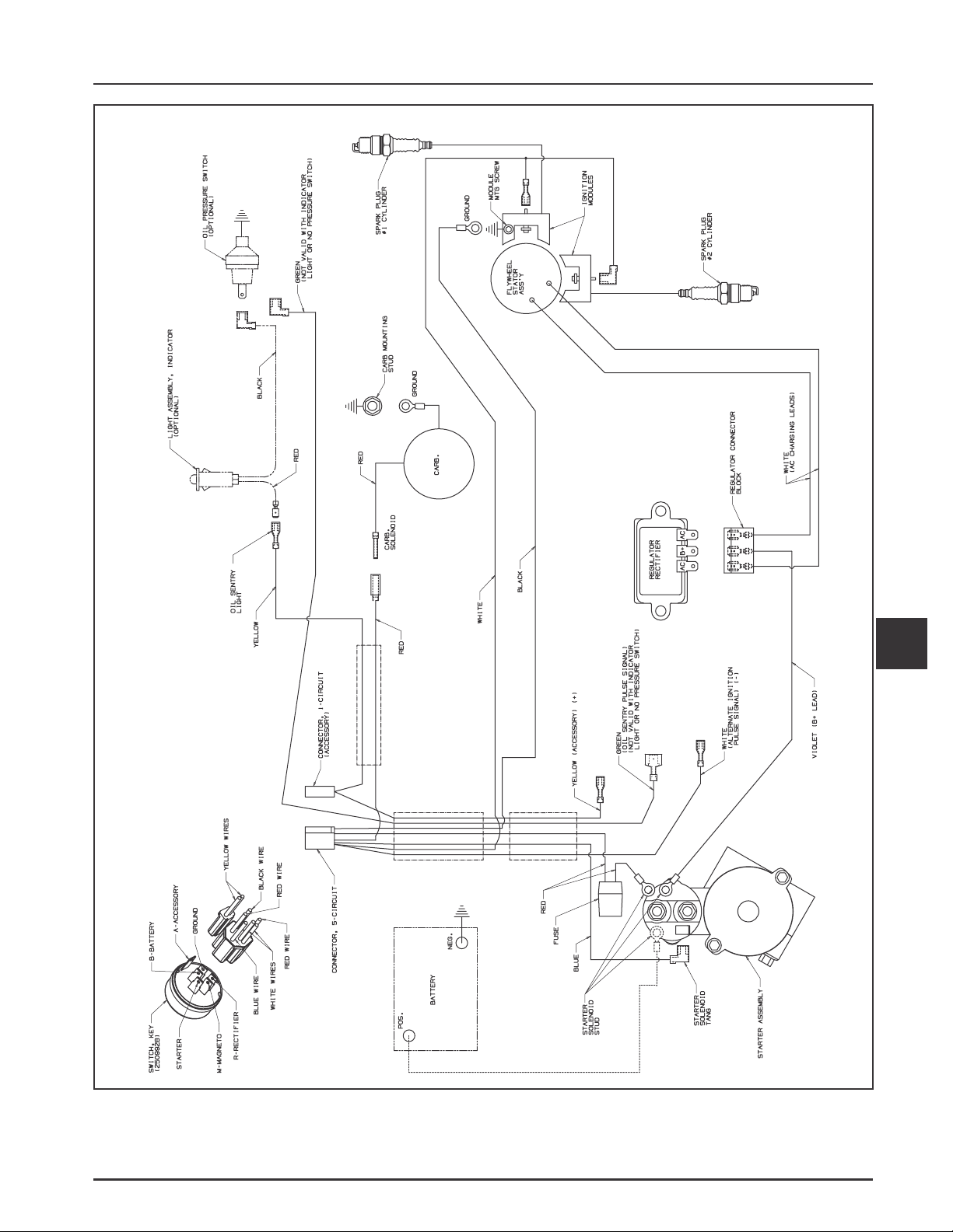
Section 7
Electrical System and Components
7
Figure 7-8. Wiring Diagram15/20/25 Amp Regulated Battery Charging System with Fixed Timing, Five Pin
Connector, Key Switch, and Fuse.
7.7
Page 54

Section 7
Electrical System and Components
Stator
The stator is mounted on the crankcase behind the
flywheel. Follow the procedures in Section 9 Disassembly and Section 11 - Reassembly if stator
replacement is necessary.
Rectifier-Regulator
The rectifier-regulator is mounted on the backing
shroud assembly. See Figure 7-9. To replace it,
disconnect the plug, remove the two mounting
screws, and ground lead.
NOTE: When installing the rectifier-regulator, take
note of the terminal positions and install the
plug correctly.
Ground
Lead
Figure 7-10. Connected Adapter.
2. Connect the tester ground lead (with spring
clamp) to the body of the rectifier-regulator.
3. Connect the red lead and one of the black leads to
the pair of terminals on the open end of the
tandem adapter lead (connections are not
location specific).
RectifierRegulator
Connector Plug
Figure 7-9. Rectifier-Regulator.
Testing of the rectifier-regulator may be performed as
follows, using the appropriate Rectifier-Regulator
Tester (see Section 2).
To Test –
NOTE: Disconnect all electrical connections attached
to the rectifier-regulator. Testing may be
performed with the rectifier-regulator
mounted or loose. The figures show the part
removed from the engine for clarity. Repeat
the applicable test procedure two or three
times to determine the condition of the part.
20/25 Amp Rectifier-Regulators
1. Connect the single lead adapter in between the
B+ (center) terminal of rectifier-regulator being
tested and the squared single end of the tandem
adapter lead. See Figure 7-10.
4. Connect the remaining black lead from the tester
to one of the outer AC terminals on the rectifierregulator. See Figure 7-11.
Figure 7-11. Connected Tester.
7.8
Page 55

Section 7
Electrical System and Components
5. Plug the tester into the proper AC outlet/power
for tester being used. Turn on the power switch.
The POWER light should be illuminated and one
of the four status lights may be on as well. See
Figure 7-12. This does not represent the
condition of the part.
Figure 7-12. Powered Tester.
6. Press the TEST button until a click is heard and
then release. See Figure 7-13. Momentarily one of
the four lights will illuminate indicating the
partial condition of the part.
*NOTE: A flashing LOW light can also occur as a
result of an inadequate ground lead
connection. Make certain the connection
location is clean and the clamp is secure.
15 Amp Rectifier-Regulators
1. Connect the tester ground lead (with spring
clamp) to the body of the rectifier-regulator
being tested.
2. Connect the tester red lead to the B+ terminal of
the rectifier-regulator and the two black tester
leads to the two AC terminals. See Figure 7-14.
Figure 7-13. Pressing T est Button.
a. If the OK (green) light comes on, disconnect
the tester black lead attached to one AC
terminal and reconnect it to the other AC
terminal. Repeat the test. If the OK (green)
light comes on again, the part is good and
may be used.
b. If any other light is displayed* in either of the
tests, the rectifier-regulator is faulty and
should not be used.
Figure 7-14. T ester Connected to 15 Amp RectifierRegulator.
3. Plug the tester into the proper AC outlet/power
for tester being used. Turn on the power switch.
See Figure 7-12. The POWER light should be
illuminated and one of the four status lights may
be on as well. This does not represent the
condition of the part.
4. Press the TEST button until a click is heard and
then release. See Figure 7-13. Momentarily one of
the four status lights will illuminate, indicating
the condition of the part.
a. If the OK (green) light comes on and stays
steady, the part is good and may be used.
b. If any other light is displayed,* the rectifier-
regulator is faulty and should not be used.
*NOTE: A flashing LOW light can also occur as a
result of an inadequate ground lead
connection. Make certain connection
location is clean and clamp is secure.
7
7.9
Page 56

Section 7
Electrical System and Components
Troubleshooting Guide
15/20/25 Amp Battery Charging Systems
When problems occur in keeping the battery charged or the battery charges at too high a rate, the problem can
usually be found somewhere in the charging system or with the battery.
NOTE: Always zero ohmmeter on each scale before testing to ensure accurate readings. Voltage tests should
be made with the engine running at 3600 RPM - no load. The battery must be good and fully charged.
Problem Test Conclusion
1. Trace B+ lead from rectifier-regulator to key
switch, or other accessible connection.
Disconnect it from switch or connection.
Connect an ammeter from loose end of B+
lead to positive terminal of battery. Connect
DC voltmeter from loose end of B+ lead to
negative terminal of battery. With engine
running at 3600 RPM, read voltage on
voltmeter.
1. If voltage is 13.8-14.7 and charge rate
increases when load is applied, the charging
system is OK and battery was fully charged.
If voltage is less than 13.8 or charge rate
does not increase when load is applied, test
stator (Tests 2 and 3).
No Charge
to Battery
Battery
Continuously
Charges at
High Rate
If voltage is 13.8 volts or more, place a
minimum load of 5 amps* on battery to
reduce voltage. Observe ammeter.
*NOTE: Turn on lights, if 60 watts or more.
Or place a 2.5 ohm, 100 watt
resistor across battery terminals.
2. Remove connector from rectifier-regulator.
With engine running at 3600 RPM, measure
AC voltage across stator leads using an AC
voltmeter.
3a. With engine stopped, measure the
resistance across stator leads using an
ohmmeter.
3b. With the engine stopped, measure the
resistance from each stator lead to ground
using an ohmmeter.
1. Perform same test as step 1 above.
2. If voltage is 28 volts or more, stator is OK.
Rectifier-regulator is faulty. Replace the
rectifier-regulator.
If voltage is less than 28 volts, stator is
probably faulty and should be replaced. Test
stator further using an ohmmeter (Test 3).
3a. If resistance is 0.064/0.2 ohms, the stator is
OK.
If the resistance is infinity ohms, stator is
open. Replace stator.
3b. If the resistance is infinity ohms (no
continuity), the stator is OK (not shorted to
ground).
If resistance (or continuity) is measured, the
stator leads are shorted to ground. Replace
stator.
1. If the voltage is 14.7 volts or less the charging
system is OK. The battery is unable to hold a
charge. Service battery or replace as
necessary.
If voltage is more than 14.7 volts, the rectifierregulator is faulty. Replace rectifier-regulator.
7.10
Page 57
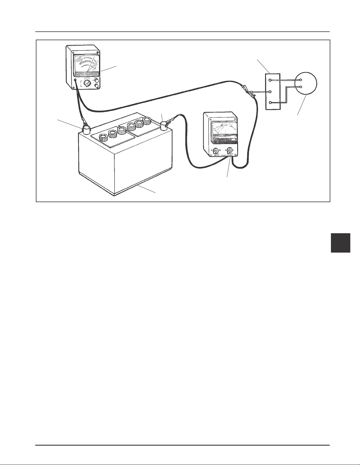
(-)
Section 7
Electrical System and Components
Rectifier-Regulator
DC V oltmeter
(+)
Flywheel
Stator
Ammeter
Battery
Figure 7-15. Connections for T esting Charging System.
Electric Starting Motors
The engines in this series use solenoid shift starters. A
Delco-Remy solenoid shift starter is typically used.
Starting Motor Precautions
NOTE: Do not crank the engine continuously for
more than 10 seconds at a time. If the engine
does not start, allow a 60 second cool-down
period between starting attempts. Failure to
follow these guidelines can burn out the
starter motor.
NOTE: If the engine develops sufficient speed to
disengage the starter but does not keep
running (a false start), the engine rotation
must be allowed to come to a complete stop
before attempting to restart the engine. If the
starter is engaged while the flywheel is
rotating, the starter pinion and flywheel ring
gear may clash, resulting in damage to the
starter.
Starter Removal and Installation
Refer to the Disassembly and Reassembly Sections for
starter removal and installation procedures.
7
Operation – Solenoid Shift Starter
When power is applied to the starter the electric
solenoid moves the drive pinion out onto the drive
shaft and into mesh with the flywheel ring gear.
When the pinion reaches the end of the drive shaft it
rotates the flywheel and cranks the engine.
When the engine starts and the start switch is
released the starter solenoid is deactivated, the drive
lever moves back, and the drive pinion moves out of
mesh with the ring gear into the retracted position.
NOTE: If the starter does not crank the engine, shut
off the starter immediately. Do not make
further attempts to start the engine until the
condition is corrected.
NOTE: Do not drop the starter or strike the starter
frame. Doing so can damage the starter.
7.11
Page 58

Section 7
Electrical System and Components
Troubleshooting Guide – S tarting Difficulties
Problem Possible Fault Correction
Starter
Does Not
Energize
Starter
Energizes
but T urns
Slowly
Battery
Wiring
Starter Switch
or Solenoid
Battery
Brushes
Transmission
or
Engine
1. Check the specific gravity of the battery. If low, recharge or
replace battery as necessary.
1. Clean corroded connections and tighten loose connections.
2. Replace wires in poor condition and with frayed or broken
insulation.
1. By-pass the switch or solenoid with a jumper wire. If starter
cranks normally, replace the faulty components. Remove and
perform individual solenoid test procedure. See pages 7.20 and
7.21.
1. Check the specific gravity of the battery. If low, recharge or
replace battery as necessary.
1. Check for excessively dirty or worn brushes and commutator.
Clean using a coarse cloth (not emery cloth).
2. Replace brushes if excessively or unevenly worn.
1. Make sure the clutch or transmission is disengaged or placed in
neutral. This is especially important on equipment with
hydrostatic drive. The transmission must be exactly in neutral to
prevent resistance which could keep the engine from starting.
2. Check for seized engine components such as the bearings,
connecting rod, and piston.
Delco-Remy Starters
Figure 7-16. Completed Delco-Remy Starter.
Starter Disassembly
1. Remove the hex nut and disconnect the positive
(+) brush lead/bracket from the solenoid
terminal.
2. Remove the three Torx head screws securing the
solenoid to the starter. See Figure 7-17.
Torx Head Screws
Figure 7-17. Removing Solenoid Screws.
3. Unhook the plunger pin from the drive lever.
Remove the gasket from the recess in the
housing. See Figures 7-18 and 7-19.
NOTE: Test procedure for checking starter solenoid
is on pages 7.20 and 7.21.
7.12
Page 59

Section 7
Electrical System and Components
Figure 7-18. Solenoid Removed from Starter.
Figure 7-19. Removing Plunger.
4. Remove the two thru (larger) bolts. See Figure
7-20.
Figure 7-21. Removing Commutator End Plate
Assembly .
6. Remove the frame from the armature and drive
end cap. See Figure 7-22.
7
Figure 7-22. Starter Frame Removed.
7. Remove the drive lever pivot bushing and
backing plate from the end cap. See Figure 7-23.
Figure 7-20. Removing Thru Bolts.
5. Remove the commutator end plate assembly,
containing the brush holder, brushes, springs,
and locking caps. Remove the thrust washer
from inside the commutator end. See Figure 7-21.
Figure 7-23. Removing Backing Plate and Pivot
Bushing.
7.13
Page 60

Section 7
Electrical System and Components
8. Take out the drive lever and pull the armature
out of the drive end cap. See Figure 7-24.
9. Remove the thrust washer from the armature
shaft. See Figure 7-24.
Figure 7-24. Armature and Lever Removed.
10. Push the stop collar down to expose the retaining
ring. See Figure 7-25.
11. Remove the retainer from the armature shaft.
Save the stop collar.
NOTE: Do not reuse the old retainer.
Figure 7-26. Removing Retaining Ring.
12. Remove the drive pinion assembly from the
armature.
13. Clean the parts as required.
Figure 7-25. Retaining Ring Detail.
NOTE: Do not soak the armature or use solvent
when cleaning. Wipe clean using a soft
cloth, or use compressed air.
Screw
Drive
End Cap
Collar
Retaining Ring
Stop
Drive
Armature
Washer
Tube
Plunger
Spring
Lever
Plate
Plug
Solenoid
Frame & Field
Brush Holder
Nut
Commutator
End Plate
Screw
7.14
Bolt
Figure 7-27. Delco-Remy Starter.
Page 61

Section 7
Electrical System and Components
Inspection
Drive Pinion
Check and inspect the following areas:
a. The pinion teeth for abnormal wear or damage.
b. The surface between the pinion and the clutch
mechanism for nicks, or irregularities which
could cause seal damage.
c. Check the drive clutch by holding the clutch
housing and rotating the pinion. The pinion
should rotate in one direction only.
Brushes and Springs
Inspect both the springs and brushes for wear,
fatigue, or damage. Measure the length of each brush.
The minimum length for each brush is 7.6 mm
(0.300 in.). See Figure 7-28. Replace the brushes if they
are worn undersize, or their condition is
questionable.
Commutator O.D.
Mica Insulation
Figure 7-29. Commutator Mica Inspection.
2. Use an ohmmeter set to the Rx1 scale. Touch the
probes between two different segments of the
commutator, and check for continuity. See Figure
7-30. Test all the segments. Continuity must exist
between all or the armature is bad.
Insulation
Check
Wear Limit Length
7.6 mm (0.300 in.)
Figure 7-28. Checking Brushes.
Armature
1. Clean and inspect the commutator (outer
surface). The mica insulation must be lower than
the commutator bars (undercut) to ensure
proper operation of the commutator. See Figure
7-29.
7
Continuity Check
Armature
Coil
Figure 7-30. Checking Armature.
3. Check for continuity between the armature coil
segments and the commutator segments. See
Figure 7-30. There should be no continuity. If
continuity exists between any two, the armature
is bad.
4. Check the armature windings/insulation for
shorting.
Shift Fork
Check that the shift fork is complete, and the pivot
and contact areas are not excessively worn, cracked,
or broken.
7.15
Page 62

Section 7
Electrical System and Components
Brush Replacement
The brushes and springs are serviced as a set (4). Use
a new Kohler Brush and Spring Kit, if replacement is
necessary.
1. Perform steps 1-5 in Starter Disassembly.
2. Remove the two screws securing the brush
holder assembly to the end cap (plate). Note the
orientation for reassembly later. See Figure 7-31.
Discard the old brush holder assembly.
Figure 7-31. Removing Brush Holder.
3. Clean the component parts as required.
Starter Service
Clean the drive lever and armature shaft. Apply
Kohler electric starter drive lubricant (see Section 2)
(Versilube G322L or Mobil Temp SHC 32) to the lever
and shaft. Clean and check the other starter parts for
wear or damage as required.
Starter Reassembly
1. Apply drive lubricant (see Section 2) to the
armature shaft splines. Install the drive pinion
onto the armature shaft.
2. Install and assemble the stop collar/retainer
assembly.
a. Install the stop collar down onto the
armature shaft with the counter bore (recess)
up.
b. Install a new retainer in the larger (rear)
groove of the armature shaft. Squeeze with a
pliers to compress it in the groove.
c. Slide the stop collar up and lock it into
place, so the recess surrounds the retainer in
the groove. If necessary, rotate the pinion
outward on the armature splines against the
retainer to help seat the collar around the
retainer.
4. The new brushes and springs come
preassembled in a brush holder with a
protective sleeve that will also serve as an
installation tool. See Figure 7-32.
Figure 7-32. Service Brush Kit.
5. Perform Steps 10-13 in the Starter Reassembly
sequence. Installation must be done after the
armature, drive lever, and frame are installed, if
the starter has been disassembled.
Figure 7-33. Installing Stop Collar and Retainer.
NOTE: Always use a new retainer. Do not reuse
old retainers which have been removed.
7.16
Page 63

Section 7
Electrical System and Components
3. Install the offset thrust (stop) washer so the
smaller offset of the washer faces the retainer/
collar. See Figure 7-34.
Thrust Washer
Figure 7-34. Installing Thrust Washer.
4. Apply a small amount of oil to the bearing in the
drive end cap, and install the armature with the
drive pinion.
5. Lubricate the fork end and center pivot of the
drive lever with drive lubricant (see Section 2).
Position the fork end into the space between the
captured washer and the rear of the pinion.
6. Slide the armature into the drive end cap, and at
the same time seat the drive lever into the
housing.
7. Install the backup washer, followed by the
rubber grommet, into the matching recess of the
drive end cap. The molded recesses in the
grommet should be out, matching and aligned
with those in the end cap. See Figure 7-36.
Figure 7-36. Installing Backup Washer and
Grommet.
8. Install the frame, with the small notch forward,
onto the armature and drive end cap. Align the
notch with the corresponding section in the
rubber grommet. Install the drain tube in the
rear cutout, if it was removed previously. See
Figure 7-37.
7
NOTE: Correctly installed, the center pivot
section of the drive lever will be flush or
below the machined surface of the
housing which receives the backup
washer. See Figure 7-35.
Figure 7-35. Installing Armature and Pivot Lever.
Figure 7-37. Installing Frame and Drain Tube.
7.17
Page 64

Section 7
Electrical System and Components
9. Install the flat thrust washer onto the
commutator end of the armature shaft. See
Figure 7-38.
Thrust
Washer
Figure 7-38. Installing Thrust W asher .
10. Starter reassembly when replacing the Brushes/
Brush Holder Assembly:
a. Hold the starter assembly vertically on the
end housing, and carefully position the
assembled brush holder assembly, with the
supplied protective tube, against the end of
the commutator/armature. The mounting
screw holes in the metal clips must be up/
out. Slide the brush holder assembly down
into place around the commutator, and
install the positive (+) brush lead grommet in
the cutout of the frame. See Figure 7-39. The
protective tube may be saved and used for
future servicing.
Starter reassembly when not replacing the Brushes/
Brush Holder Assembly:
a. Carefully unhook the retaining caps from
over each of the brush assemblies. Do not lose
the springs. See Figure 7-40.
Figure 7-40. Removing Retaining Clips.
b. Position each of the brushes back in their
slots so they are flush with the I.D. of the
brush holder assembly. Insert the Brush
Installation Tool (with extension), or use the
tube described above from a prior brush
installation, through the brush holder
assembly, so the holes in the metal mounting
clips are up/out.
c. Install the brush springs and snap on the four
retainer caps. See Figure 7-41.
Figure 7-39. Installing Brush Holder Assembly with
Supplied Tube.
7.18
Figure 7-41. Brush Installation T ool with Extension.
Page 65
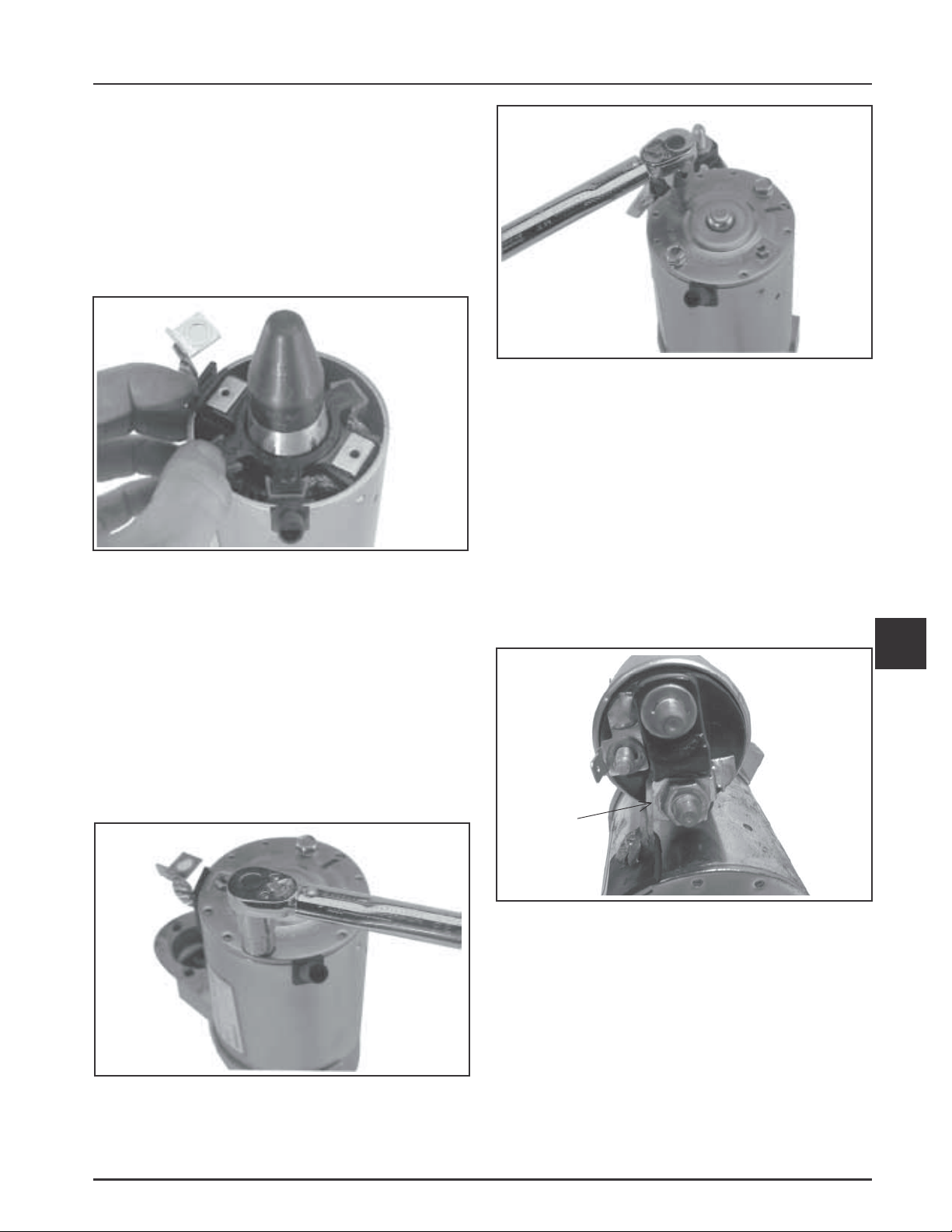
d. Hold the starter assembly vertically on the
end housing, and carefully place the tool
(with extension) and assembled original
brush holder assembly onto the end of the
armature shaft. Slide the brush holder
assembly down into place around the
commutator, install the positive (+) brush
lead grommet in the cutout of the frame. See
Figure 7-42.
Section 7
Electrical System and Components
Figure 7-44. T orquing Brush Holder Screws.
13. Hook the plunger behind the upper end of the
drive lever, and install the spring into the
solenoid. Insert the three mounting screws
through the holes in the drive end cap. Use these
to hold the solenoid gasket in position, then
mount the solenoid. Torque the screws to
4.0-6.0 N·m (35-53 in. lb.).
Figure 7-42. Installing Brush Holder Assembly
using T ool with Extension.
11. Install the end cap onto the armature and frame,
aligning the thin raised rib in the end cap with
the corresponding slot in the grommet of the
positive (+) brush lead.
12. Install the two thru bolts, and the two brush
holder mounting screws. Torque the thru bolts to
5.6-9.0 N·m (49-79 in. lb.). Torque the brush
holder mounting screws to 2.5-3.3 N·m
(22-29 in. lb.). See Figures 7-43 and 7-44.
14. Connect the positive (+) brush lead/bracket to the
solenoid and secure with the hex nut. Torque the
nut to 8-11 N·m (71-97 in. lb.). Do not
overtighten. See Figure 7-45.
7
Positive
Brush
Lead
Figure 7-45. Positive (+) Brush Lead Connection.
Figure 7-43. T orquing Thru Bolts.
7.19
Page 66

Section 7
Electrical System and Components
Solenoid Test Procedure
Solenoid Shift Style Starters
Disconnect all leads from the solenoid including the
positive brush lead attached to the lower stud
terminal. Remove the mounting hardware and
separate the solenoid from the starter for testing.
Test 1. Solenoid Pull-In Coil/Plunger Actuation
T est.
Use a 12 volt power supply and two test leads.
Connect one lead to the flat spade S/start terminal on
the solenoid. Momentarily* connect the other lead to
the lower large post terminal. See Figure 7-46.
When the connection is made the solenoid should
energize (audible click), and the plunger retract.
Repeat the test several times. If the solenoid fails to
activate, it should be replaced.
*NOTE: DO NOT leave the 12 volt test leads
connected to the solenoid for any time
over what is necessary for performing
each of the individual tests. Internal
damage to the solenoid may otherwise
occur.
12 volt T est Leads
Momentary
Connection Only
VOM Leads
Figure 7-47. T esting Pull-In Coil/Solenoid Contact
Continuity .
T est 3. Solenoid Hold-In Coil Function Test.
Connect one 12 volt test lead to the flat spade S/start
terminal on the solenoid, and the other lead to the
body or mounting surface of the solenoid. Then,
manually push the plunger In and check if the
Hold-In coil holds the plunger retracted. See Figure
7-48. Do not allow the test leads to remain connected
to the solenoid for a prolonged period of time. If the
plunger fails to stay retracted, the solenoid should be
replaced.
12 volt T est Leads
Momentary
Connection Only
Figure 7-46. T esting Pull-In Coil/Plunger Actuation.
T est 2. Solenoid Pull-In Coil/Cont act Continuity
T est.
Use an ohmmeter set to the audible or Rx2K scale, and
connect the two ohmmeter leads to the two large post
terminals. Perform the preceding test (1) and check for
continuity. See Figure 7-47. The ohmmeter should
indicate continuity, if no continuity is indicated the
solenoid should be replaced. Repeat test several times
to confirm condition.
Manually Push
Plunger In
12 volt T est Leads
Connect Only Long
Enough toT est
Figure 7-48. T esting Hold-In Coil/Function T est.
7.20
Page 67

T est 4. Solenoid Hold-In Coil/Contact Continuity
T est.
Use an ohmmeter set to the audible or Rx2K scale, and
connect the two ohmmeter leads to the two large post
terminals. Perform the preceding test (3) and check for
continuity. See Figure 7-49. The meter should indicate
continuity. If no continuity is indicated, the solenoid
should be replaced. Repeat test several times to
confirm condition.
Section 7
Electrical System and Components
VOM Meter
Leads
Plunger
Pushed In
12 volt T est Leads
Figure 7-49. T esting Hold-In Coil/Solenoid Cont act
Continuity.
7
7.21
Page 68

Section 8
Disassembly
Section 8
Disassembly
WARNING: Accident al St arts!
Disabling engine. Accidental starting can cause severe injury or death. Before working on the engine or equipment,
disable the engine as follows: 1) Disconnect the spark plug lead(s). 2) Disconnect negative (-) battery cable from battery.
General
Clean all parts thoroughly as the engine is
disassembled. Only clean parts can be accurately
inspected and gauged for wear or damage. There are
many commercially available cleaners that will
quickly remove grease, oil and grime from engine
parts. When such a cleaner is used, follow the
manufacturer’s instructions and safety precautions
carefully.
Make sure all traces of the cleaner are removed before
the engine is reassembled and placed into operation.
Even small amounts of these cleaners can quickly
break down the lubricating properties of engine oil.
Typical Disassembly Sequence
The following sequence is suggested for complete
engine disassembly. The sequence can be varied to
accommodate options or special equipment.
1. Disconnect spark plug leads.
2. Shut off fuel supply.
3. Drain oil from crankcase and remove oil filter.
4. Remove muffler.
5. Remove cylinder shrouds and blower housing.
6. Remove electric starter motor.
7. Remove air cleaner assembly.
8. Remove control bracket, governor springs, and
lever.
9. Remove carburetor.
10. Remove Oil Sentry™ (if equipped).
11. Remove baffles and intake manifold.
12. Remove oil cooler.
13. Remove oil filter housing and oil filter adapter.
14. Remove ignition modules.
15. Remove grass screen and cooling fan
16. Remove flywheel.
17. Remove stator, rectifier-regulator, and wiring
harness.
18. Remove backing shroud assembly.
19. Remove spark plugs.
20. Remove valve covers and fuel pump.
21. Remove cylinder heads and hydraulic lifters.
22. Disassemble cylinder heads.
23. Remove breather assembly.
24. Remove oil reservoir and pickup screen.
25. Remove closure plate assembly.
26. Remove camshaft.
27. Remove connecting rods with pistons and rings.
28. Remove crankshaft.
29. Removal of governor gear assembly.
30. Remove governor yoke, cross shaft, and seal.
31. Remove lifter feed cover and gaskets.
32. Remove flywheel and PTO end oil seals.
33. Removal of main bearings.
Disconnect Spark Plug Leads
1. Disconnect the leads from the spark plugs. See
Figure 8-1.
NOTE: Pull on boot only, to prevent damage to
spark plug lead.
Figure 8-1. Disconnect Both Spark Plug Leads.
8
8.1
Page 69

Section 8
Disassembly
Shut Off Fuel Supply
Drain Oil from Crankcase and Remove Oil
Filter
1. Clean the oil filter and housing area. Remove and
discard the oil filter. See Figure 8-2.
Figure 8-2. Removing Oil Filter.
2. Remove the dipstick and one of the oil drain
plugs.
3. Allow ample time for the oil to drain from the
crankcase.
Remove Muffler
1. Remove the exhaust system and attaching
hardware from the engine.
Remove Cylinder Shrouds and Blower
Housing
1. Remove the top mounting screw and loosen the
two shoulder screws on each side. Lift off the
two cylinder shrouds. See Figure 8-5.
Cylinder
Shroud
Figure 8-3. Removing Dipstick from Tube.
Figure 8-5. Removing Cylinder Shrouds.
2. Remove the four mounting screws and separate
the blower housing from the lower half. See
Figure 8-6.
Figure 8-6. Removing Blower Housing.
Drain Plug
(Starter Side
Shown)
Figure 8-4. Oil Drain Plug Location.
8.2
Page 70

Section 8
Disassembly
Remove Electric Starter Motor
1. Disconnect the leads from the starter.
2. Remove the two hex flange screws and starter.
See Figure 8-7.
Mounting
Screws
Figure 8-7. Removing Electric Starter.
Remove Air Cleaner Assembly
1. Disconnect the breather hose from the air cleaner,
and the formed vent hose from the vent port on
the carburetor.
3. Remove the two screws securing the air cleaner
and main control bracket to the intake manifold
bosses. See Figure 8-9.
Mounting
Screws
Figure 8-9. Mounting Screws.
4. Remove the air cleaner as an assembly from the
engine. See Figure 8-10.
2. Remove the four hex flange nuts, ground lead,
and choke return spring bracket from the
mounting studs. See Figure 8-8.
Vent Hose
Mounting
Nuts
Breather
Hose
Bracket
Figure 8-8. Air Cleaner Mounting Details.
8
Figure 8-10. Removing Air Cleaner Assembly.
8.3
Page 71

Section 8
Disassembly
Removing Control Bracket, Governor
Springs, and Lever
1. Unhook the governed idle and governor springs
from the controls on the main bracket and
governor lever. Note the color, location and
position of each. See Figure 8-11.
2. Disconnect the throttle linkage and dampening
spring from the governor lever at the small
bushing. See Figure 8-11.
3. Carefully pry off the pal nut, remove the two
washers (note assembly order), and disconnect
the choke linkage from the pivot lever. Do not lose
any parts. Secure remaining pivot parts with
tape to avoid losing them. Always use a new pal
nut during reassembly. See Figure 8-11.
Pal Nut
Governor
Springs
Governor
Lever
Figure 8-13. Removing Governor Lever.
Remove Carburetor
WARNING: Explosive Fuel!
Gasoline is extremely flammable and its vapors can explode if
ignited. Store gasoline only in approved containers, in well
ventilated, unoccupied buildings, away from sparks or flames.
Do not fill the fuel tank while the engine is hot or running,
since spilled fuel could ignite if it comes in contact with hot
parts or sparks from ignition. Do not start the engine near
spilled fuel. Never use gasoline as a cleaning agent.
Throttle
Choke
Linkage
Figure 8-11. Disconnect Control Linkages and
Governor Springs.
4. Remove the rear mounting screw on each side
and lift off the control bracket. See Figure 8-12.
Control Bracket
Mounting
Screw
Linkage
1. Disconnect the fuel shut-off solenoid lead.
2. Remove the fuel inlet hose from the carburetor or
fuel pump. Properly contain any remaining fuel.
3. Remove the carburetor and linkages with choke
return components as an assembly. See Figure
8-14.
Figure 8-14. Removing Carburetor.
Figure 8-12. Removing Control Bracket.
5. Loosen the hex flange nut and remove the
governor lever from cross shaft. See Figure 8-13.
8.4
4. Remove the carburetor gasket.
5. The carburetor and linkages can be separated as
necessary.
Page 72

Section 8
Disassembly
Remove Oil Sentry™ (If Equipped)
1. Disconnect the lead from the Oil Sentry™ switch.
2. Remove the Oil Sentry™ switch from the closure
plate. See Figure 8-15.
Pressure
Switch
Figure 8-15. Oil Sentry™ Switch Location in
Closure Plate.
Remove Baffles and Intake Manifold
1. Remove the screws securing the valley baffles to
the cylinder heads and backing shroud assembly.
2. Remove the four screws securing each of the
outer cylinder baffles in place. Two of the screws
are accessed from the backing shroud side. See
Figure 8-17.
Mounting
Screws
Figure 8-17. Removing Outer Cylinder Baffles.
3. Remove the four hex flange screws securing the
intake manifold to the cylinder heads. Cut any
wire ties that secure the wiring harness or leads
to the intake manifold.
4. Remove the intake manifold and gaskets. See
Figure 8-18.
Figure 8-16. Removing Valley Baffles.
Mounting
Locations
Figure 8-18. Removing Intake Manifold.
Mounting
Locations
8
8.5
Page 73
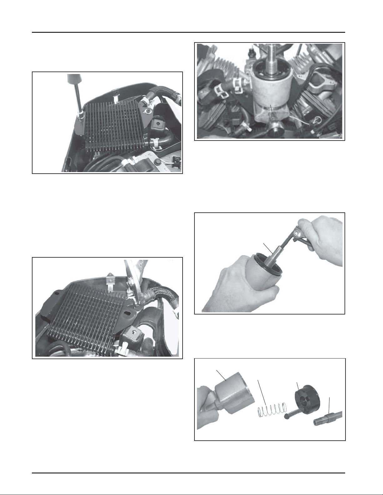
Section 8
Disassembly
Remove Oil Cooler
1. Remove the two oil cooler mounting screws. Do
not lose any washers (if used). See Figure 8-19.
Figure 8-19. Removing Oil Cooler Mounting
Screws.
2. Loosen the clamps and disconnect each of the
hoses from the oil cooler. See Figure 8-20.
Housing
Mounting
Screw
Figure 8-21. Removing Oil Filter Housing From
Adapter .
Perform the following only if the oil filter housing
assembly requires individual servicing.
a. Remove the nipple from the cup and oil filter
housing. See Figure 8-22.
NOTE: New clamps are recommended any time
disassembly is performed, or if clamps
have been loosened (expanded) several
times.
Figure 8-20. Disconnecting Hoses From Oil Cooler.
Remove Oil Filter Housing and Oil Filter
Adapter
1. Remove the screw securing the oil filter housing
and individual O-Rings to the adapter. Carefully
separate the parts. See Figure 8-21.
Nipple
Figure 8-22. Removing Nipple.
b. Remove the oil filter cup and spring from
housing. See Figure 8-23.
Housing
Spring
Cup
Nipple
NOTE: Further disassembly of the oil filter
housing assembly is not required unless
individual servicing must be performed.
Follow substeps a, b, and c.
8.6
Figure 8-23. Disassembled Cup and Spring.
Page 74

c. Remove the rubber valve and spring from the
cup. See Figure 8-24.
Section 8
Disassembly
Cup
Valve
Figure 8-24. Rubber Valve and Spring Removed
from Cup.
2. Remove the screw securing the oil filter adapter
and individual O-Rings to the crankcase, then
carefully separate the parts. See Figure 8-25.
Spring
Adapter
Mounting
Mounting
Screw
Screw
Ignition
Modules
Figure 8-26. Removing Ignition Modules.
Remove Grass Screen and Cooling Fan
1. Remove the screws, attaching hardware and hex
studs securing the grass screen, stiffeners and
cooling fan to the flywheel. See Figures 8-27, 8-28
and 8-29.
Adapter
Figure 8-25. Removing Oil Filter Housing Adapter.
Remove Ignition Modules
1. Rotate the flywheel so the magnet is away from
the modules.
2. Remove the mounting screws and disconnect the
kill lead from the ignition modules. Note the
position of ignition modules. See Figure 8-26.
8
Figure 8-27. Removing Grass Screen Fasteners.
Figure 8-28. Removing Mounting Studs.
8.7
Page 75

Section 8
Disassembly
Mounting
Mounting
Screws
Screws
Figure 8-29. Removing Fan.
Remove Flywheel
1. Use a flywheel strap wrench or holding tool (see
Section 2) to hold the flywheel and loosen the hex
flange screw securing the flywheel to the
crankshaft. See Figure 8-30.
NOTE: Always use a flywheel strap wrench or
holding tool to hold the flywheel when
loosening or tightening the flywheel
screw. Do not use any type of bar or
wedge to hold the flywheel. Use of such
tools could cause the flywheel to become
cracked or damaged.
Figure 8-31. Removing Flywheel with a Puller.
4. Remove the woodruff key from the crankshaft.
Remove Stator, Rectifier-Regulator, and
Wiring Harness
1. Disconnect the plug from the rectifier-regulator.
If the B+ (center) lead must be removed from the
plug, use a small flat tool to bend the locking
tang. Then remove the lead.
2. Remove the mounting screws securing the
rectifier-regulator to the backing shroud
assembly. Note the location of the ground lead. If
the rectifier-regulator is not being replaced, it
may remain mounted to the lower blower
housing. See Figure 8-32.
Ground
Lead
Figure 8-30. Removing Flywheel Fastener Using
Holding T ool.
2. Remove the hex flange screw and washer.
3. Use a puller to remove the flywheel from the
crankshaft. See Figure 8-31.
NOTE: Always use a flywheel puller to remove
the flywheel from the crankshaft. Do
not strike the crankshaft or flywheel, as
these parts could become cracked or
damaged.
8.8
RectifierRegulator
Plug
Figure 8-32. Rectifier-Regulator Details.
3. Remove the two screws securing the stator to the
crankcase and carefully separate the stator wires
from the blower housing clips.
Page 76

Molded Clips
Mounting
Screws
Figure 8-33. Removing Stator.
4. Unhook the wiring harness from the molded
clips if it is being serviced separately. See Figure
8-34.
Wiring
Harness
Molded
Clip
Molded
Clip
Section 8
Disassembly
Remove Spark Plugs
1. Remove the spark plug from each cylinder head.
Figure 8-36. Removing Spark Plugs.
Remove Valve Covers and Fuel Pump
WARNING: Explosive Fuel!
Gasoline is extremely flammable and its vapors can explode if
ignited. Store gasoline only in approved containers, in well
ventilated, unoccupied buildings, away from sparks or flames.
Do not fill the fuel tank while the engine is hot or running,
since spilled fuel could ignite if it comes in contact with hot
parts or sparks from ignition. Do not start the engine near
spilled fuel. Never use gasoline as a cleaning agent.
Figure 8-34. Removing Wiring Harness.
Remove Backing Shroud Assembly
1. Remove the four mounting screws securing the
backing shroud assembly to the crankcase. See
Figure 8-35.
Backing
Shroud
Assembly
Screws
Screws
Figure 8-35. Removing Backing Shroud Mounting
Screws.
NOTE: Based on the style of fuel pump used refer to
the following when removing valve covers.
8
Mechanical Fuel Pump
1. The mechanical fuel pump is part of the valve
cover and not serviced separately. Remove with
the valve cover. Disconnect the fuel lines at the
fuel pump fittings. See Figure 8-37. Properly
contain any remaining fuel.
Figure 8-37. Disconnecting Fuel Lines.
8.9
Page 77

Section 8
Disassembly
Electric Fuel Pump
1. Removal will be determined based on mounted
location and application. Disconnect the lead
connections, fuel line connections, and mounting
hardware as required. Properly contain any
remaining fuel.
Valve Covers
1. Remove the screw and grommet securing each
valve cover.
2. Remove the valve cover and gasket from each
cylinder head. Note the locations of individual
valve covers if they are different. See Figure 8-38.
Spacer
Washers
Figure 8-40. Removing Cylinder Head Fasteners.
3. Mark the position of the push rods as either
intake or exhaust and cylinder 1 or 2. Push rods
should always be reinstalled in the same
positions.
Figure 8-38. Removing Valve Covers.
Remove Cylinder Heads and Hydraulic
Lifters
1. Remove the pipe plug from the cylinder head to
access the screw in the upper center location. See
Figure 8-39.
Pipe Plug
4. Carefully remove the push rods, cylinder head
and head gasket. See Figure 8-41.
5. Repeat the procedure for the other cylinder head.
Figure 8-41. Removing Cylinder Head Assembly.
6. Remove the lifters from the lifter bores. Use a
Hydraulic Lifter Tool. Do not use a magnet to
remove lifters. Mark the lifters by location, as
either intake or exhaust and cylinder 1 or 2.
Hydraulic lifters should always be reinstalled in
the same position. See Figures 8-42 and 8-43.
Figure 8-39. Removing Pipe Plug.
2. Remove the five hex flange screws securing each
cylinder head. Note the locations of washers and
spacer. See Figure 8-40.
8.10
NOTE: The exhaust lifters are located on the
output shaft side of the engine while the
intake lifters are located on the fan side
of the engine. The cylinder head number
is embossed on the outside of each
cylinder head. See Figure 8-43.
Page 78

Section 8
Disassembly
Figure 8-42. Removing Hydraulic Lifters.
Match
Numbers
Figure 8-43. Match Numbers on Cylinder Barrel
and Heads.
Disassemble Cylinder Heads
1. Remove the two hex flange screws, rocker arm
pivots, and rocker arms from the cylinder head.
See Figure 8-44.
Figure 8-45. Removing Valves with Valve Spring
Compressor.
3. Once the valve spring is compressed, remove the
following items. See Figures 8-46 and 8-47.
• Valve spring keepers
• Valve spring retainers
• Valve springs
• Valve spring caps
• Intake and exhaust valves (mark position)
• Valve stem seals
8
Figure 8-44. Removing Rocker Arms.
2. Compress the valve springs using a valve spring
compressor. See Figure 8-45.
Figure 8-46. Valve Train Components.
Valve Stem Seals
Figure 8-47. Valve Stem Seals.
8.11
Page 79

Section 8
Disassembly
NOTE: These engines use valve stem seals on
the intake and exhaust valves. Use a
new seal whenever valves are removed,
or if the seal is deteriorated in any way.
Never reuse an old seal.
4. Repeat the above procedure for the other
cylinder head. Do not interchange parts from
one cylinder head to the other.
Remove Breather Assembly
1. Remove the four fasteners securing the breather
assembly, breather adapter (style based on spec),
and gaskets to the crankcase.
2. Carefully break the gasket seals and remove all
parts. Do not pry on the sealing surfaces as it
could cause damage resulting in leaks. Note the
assembly and orientation of parts. See Figures
8-48 and 8-49.
Breather
Remove Oil Reservoir and Pickup Screen
1. Remove the eight screws securing the oil
reservoir and gasket to engine.
Figure 8-50. Removing Oil Reservoir.
2. Remove the mounting screw and carefully work
the pickup screen off the end of the pickup tube.
See Figure 8-51.
Breather
Adapter
Figure 8-48. Removing Breather Assembly .
Breather Adapter
(Certain Models)
Gasket
Pickup T ube
Pickup Screen
Mounting Screw
Figure 8-51. Removing Pickup Screen.
Figure 8-49. Removing Breather Adapter.
8.12
Page 80

Section 8
Disassembly
Remove Closure Plate Assembly
1. Remove the fourteen hex flange screws securing
the closure plate to the crankcase. See Figure
8-52.
Figure 8-52. Removing Closure Plate Screws.
2. Locate the two protruding tabs on the closure
plate. Carefully tap to break the gasket seal. Do
not pry on the sealing surfaces as this could
cause leaks. Separate the closure plate from the
crankcase. See Figure 8-53 and 8-54. Remove the
old gasket.
Oil Pump Assembly
The oil pump is mounted to the inside of the closure
plate. If service is required, refer to the service
procedures under Oil Pump Assembly in Section 9.
Remove Camshaft
1. Remove the camshaft and shim (if used). See
Figure 8-55.
Figure 8-55. Removing Camshaft.
Remove Connecting Rods with Pistons
and Rings
1. Remove the two hex flange screws securing the
closest connecting rod end cap. Remove the end
cap. See Figure 8-56.
Tab
Figure 8-53. Location of T abs.
Figure 8-54. Removing Closure Plate.
8
Tab
Figure 8-56. Removing Connecting Rod Screws.
NOTE: If a carbon ridge is present at the top of
either cylinder bore, use a ridge reamer
tool to remove the ridge before
attempting to remove the piston.
8.13
Page 81

Section 8
Disassembly
Figure 8-57. Remove Connecting Rod Caps.
NOTE: The cylinders are numbered on the
crankcase. Use the numbers to mark
each end cap, connecting rod and piston
for reassembly. Do not mix end caps
and connecting rods.
2. Carefully remove the connecting rod and piston
assembly from the cylinder bore. See Figure 8-58.
Figure 8-59. Removing Crankshaft.
Removal of Governor Gear Assembly
The governor gear is held onto the shaft by small
molded tabs in the gear. When the gear is
removed from the shaft, these tabs are destroyed and
the gear must be replaced. Therefore, remove the gear
only if absolutely necessary. If the governor cross
shaft, yoke, or gear condition does not require
removal, the governor gear may be left in place. If
removal is necessary, perform as follows:
1. Remove the locking tab thrust washer and note
orientation.
2. Using a screwdriver, carefully pry upward to
unseat the governor gear assembly from the
governor gear shaft. Remove the regulating pin
and governor gear assembly. See Figure 8-60.
Governor Gear
Figure 8-58. Removing Piston/Connecting Rod
Assemblies.
3. Repeat the above procedures for the other
connecting rod and piston assembly.
Remove Crankshaft
1. Carefully pull the crankshaft from the crankcase.
See Figure 8-59. Note thrust washers and shims
if used.
8.14
Figure 8-60. Removing Governor Gear.
3. Inspect the governor gear shaft for wear or
damage. Remove the shaft only if replacement is
needed.
Page 82

Section 8
Disassembly
Remove Governor Yoke, Cross Shaft, and
Seal
1. Remove the two mounting screws securing the
yoke to the governor cross shaft. See Figure
8-61.
Figure 8-61. Removing Cross Shaft/Y oke Screws.
2. Pull the governor cross shaft out of the crankcase
and remove the seal.
Remove Lifter Feed Chamber Cover and
Gaskets
1. Remove the three screws securing the lifter feed
chamber baffle (some models only), cover, and
gaskets. Carefully separate the parts from the
crankcase. See Figure 8-62.
Remove Flywheel and PTO End Oil Seals
1. Remove the oil seals from the crankcase and
closure plate using a seal puller. See Figure 8-63.
Figure 8-63. Removing Oil Seals.
Removal of Main Bearings
NOTE: Flywheel and PTO side main bearings
should only be removed if replacement is
required due to wear. If removal is
performed, use a press and support the
casting surface around the bearing flange.
Do not press against or support by the
gasket/outer perimeter surface. See Figure
8-64.
Screws
Figure 8-62. Removing Lifter Feed Chamber Cover
Components.
Baffle (Some
Models Only)
Cover
Gasket
8
Support
This Surface
Figure 8-64. Support Surface Details.
8.15
Page 83

Inspection and Reconditioning
Section 9
Inspection and Reconditioning
Section 9
This section covers the operation, inspection, and
repair/reconditioning of major internal engine
components. The following components are not
covered in this section. They are covered in sections
of their own:
Air Cleaner, Section 4
Carburetor & External Governor, Section 5
Ignition, Charging, & Electric Starter, Section 7
Clean all parts thoroughly. Only clean parts can be
accurately inspected and gauged for wear or damage.
There are many commercially available cleaners that
will quickly remove grease, oil, and grime from
engine parts. When such a cleaner is used, follow the
manufacturer’s instructions and safety precautions
carefully. Make sure all traces of the cleaner are
removed before the engine is reassembled and placed
into operation. Even small amounts of these cleaners
can quickly break down the lubricating properties of
engine oil.
Use an aerosol gasket remover, paint stripper, or
lacquer thinner to remove any old gasket material.
Apply the solvent, allow time for it to work, and then
brush the surface with a brass wire brush. After all
old material is removed, clean the surface with
isopropyl alcohol, lacquer thinner, or aerosol
electrical contact cleaner. Do not scrape the surfaces,
as any scratches, nicks, or burrs can result in leaks.
See Service Bulletin 252 for further information.
Refer to A Guide to Engine Rebuilding (TP-2150-A) for
additional information. Measurement Guide
(TP-2159-B) and Engine Inspection Data Record
(TP-2435) are also available; use these to record
inspection results.
Camshaft
Inspection and Service
Check the lobes of the camshaft for wear or damage.
See Section 1 for minimum lift and/or dimensional
specifications. Inspect the cam gear for badly worn,
chipped, or missing teeth. Replacement of the
camshaft will be necessary if any of these conditions
exist.
Crankshaft
Inspection and Service
Inspect the gear teeth of the crankshaft. If the teeth are
badly worn, chipped, or some are missing,
replacement of the crankshaft will be necessary.
Inspect the crankshaft bearing surfaces for scoring,
grooving, etc. Replaceable bearings are used in the
crankshaft bore of the closure plate and/or crankcase.
Do not replace bearings unless they show signs of
damage or are out of running clearance specifications.
If the crankshaft turns easily, without noise, and there
is no evidence of scoring, grooving, etc., on the races
or bearing surfaces, the bearings can be reused.
9
Inspect the crankshaft keyways. If they are worn or
chipped, replacement of the crankshaft will be
necessary.
Inspect the crankpin for score marks or metallic
pickup. Slight score marks can be cleaned with crocus
cloth soaked in oil. If the wear limits, as stated in
Specifications and Tolerances are exceeded, it will be
necessary to either replace the crankshaft or regrind
the crankpin to 0.25 mm (0.010 in.) undersize. If
reground, a 0.25 mm (0.010 in.) undersize connecting
rod (big end) must then be used to achieve proper
running clearance. Measure the crankpin for size,
taper, and out-of-round.
9.1
Page 84
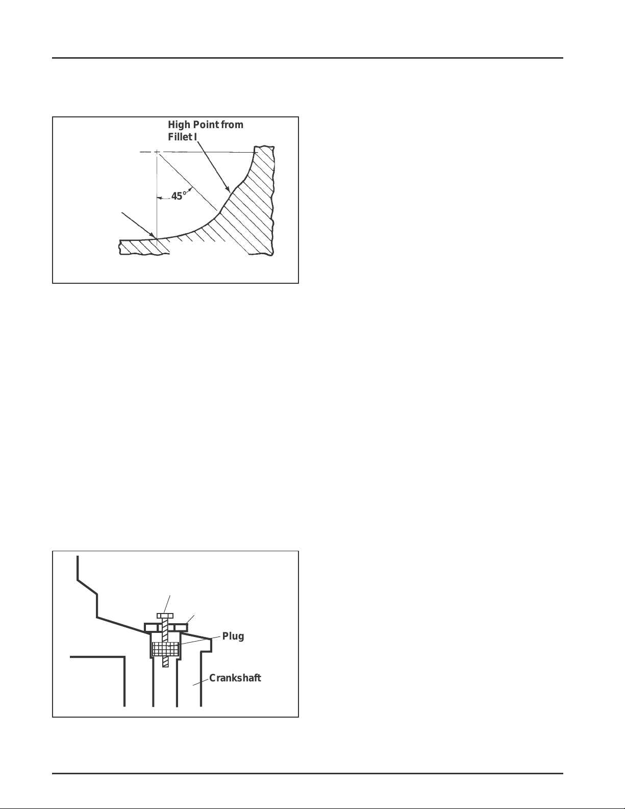
Section 9
8
8
8
Inspection and Reconditioning
NOTE: If the crankpin is reground, visually check to
ensure that the fillet blends smoothly with
the crankpin surface. See Figure 9-1.
High Point from
Fillet Intersections
The Fillet Must
Blend Smoothly
with the Bearing
Journal Surface
45°
Minimum
This Fillet Area
Must Be
Completely Smooth
Figure 9-1. Crankpin Fillets.
The connecting rod journal can be ground one size
under. When grinding a crankshaft, grinding stone
deposits can get caught in the oil passages, which
could cause severe engine damage. Removing the
crankpin plug when the crankshaft is ground
provides easy access for removing any grinding
deposits that may collect in the oil passages.
Use the following procedure to remove and replace
the plug.
Procedure to Install New Plug:
1. Use a single cylinder camshaft pin, Kohler Part
No. 47 380 09-S as a driver and tap the plug into
the plug bore until it seats at the bottom of the
bore. Make sure the plug is tapped in evenly to
prevent leakage.
Crankcase
Inspection and Service
Check all gasket surfaces to make sure they are free of
gasket fragments. Gasket surfaces must also be free of
deep scratches or nicks.
Inspect the main bearing (if so equipped) for wear or
damage (refer to Section 1, Specifications, Tolerances,
and Special Torque Values). Replace the bearing or
crankcase using a miniblock or short block as
required.
Check the cylinder bore for scoring. In severe cases,
unburned fuel can cause scuffing and scoring of the
cylinder wall. It washes the necessary lubricating oils
off the piston and cylinder wall. As raw fuel seeps
down the cylinder wall, the piston rings make metal
to metal contact with the wall. Scoring of the cylinder
wall can also be caused by localized hot spots
resulting from blocked cooling fins or from
inadequate or contaminated lubrication.
Procedure to Remove Crankshaft Plug:
1. Drill a 3/16" hole through the plug in the
crankshaft.
2. Thread a 3/4" or 1" long self-tapping screw with
a flat washer into the drilled hole. The flat
washer must be large enough to seat against the
shoulder of the plug bore. See Figure 9-2.
Self-Tapping Screw
Flat Washer
234567
234567
234567
Plug
Crankshaft
Figure 9-2. Removing Crankpin Plug.
If the cylinder bore is badly scored, excessively worn,
tapered, or out-of-round, resizing is necessary. Use an
inside micrometer to determine the amount of wear
(refer to the Specifications, Tolerances, and Special
Torque Values, in Section 1), then select the nearest
suitable oversize of either 0.25 mm (0.010 in.) or
0.50 mm (0.020 in.). Resizing to one of these oversizes
will allow usage of the available oversize piston and
ring assemblies. Initially, resize using a boring bar,
then use the following procedures for honing the
cylinder.
Honing
While most commercially available cylinder hones
can be used with either portable drills or drill
presses, the use of a low speed drill press is preferred
as it facilitates more accurate alignment of the bore in
relation to the crankshaft crossbore. Honing is best
accomplished at a drill speed of about 250 RPM and
60 strokes per minute. After installing coarse stones in
hone, proceed as follows:
3. Tighten the self-tapping screw until it draws the
plug out of the crankshaft.
9.2
Page 85

Section 9
Inspection and Reconditioning
1. Lower hone into bore and after centering, adjust
so the stones are in contact with the cylinder
wall. Use of a commercial cutting-cooling agent
is recommended.
2. With the lower edge of each stone positioned
even with the lowest edge of the bore, start drill
and honing process. Move the hone up and down
while resizing to prevent the formation of
cutting ridges. Check the size frequently.
NOTE: Kohler pistons are custom-machined to
exacting tolerances. When oversizing a
cylinder, it should be machined exactly
0.25 mm (0.010 in.) or 0.50 mm (0.020 in.)
over the new diameter (Section 1). The
corresponding oversize Kohler replacement
piston will then fit correctly.
3. When the bore is within 0.064 mm (0.0025 in.) of
the desired size, remove the coarse stones and
replace them with burnishing stones. Continue
with the burnishing stones until the bore is
within 0.013 mm (0.0005 in.) of the desired size
and then use finish stones (220-280 grit) and
polish the bore to its final size. A crosshatch
should be observed if honing is done correctly.
The crosshatch should intersect at
approximately 23°-33° off the horizontal. Too flat
an angle could cause the rings to skip and wear
excessively, and too steep an angle will result in
high oil consumption. See Figure 9-3.
Clean Cylinder Bore After Honing
Proper cleaning of the cylinder walls following boring
and/or honing is very critical to a successful overhaul.
Machining grit left in the cylinder bore can destroy an
engine in less than one hour of operation after a
rebuild.
The final cleaning operation should always be a
thorough scrubbing with a brush and hot, soapy
water. Use a strong detergent that is capable of
breaking down the machining oil while maintaining a
good level of suds. If the suds break down during
cleaning, discard the dirty water and start again with
more hot water and detergent. Following the
scrubbing, rinse the cylinder with very hot, clear
water, dry it completely, and apply a light coating of
engine oil to prevent rusting.
Measuring Piston-to-Bore Clearance
Before installing the piston into the cylinder bore, it is
necessary that the clearance be accurately checked.
This step is often overlooked, and if the clearances are
not within specifications, engine failure will usually
result.
NOTE: Do not use a feeler gauge to measure piston-
to-bore clearance – it will yield inaccurate
measurements. Always use a micrometer.
Use the following procedure to accurately measure
the piston-to-bore clearance:
1. Use a micrometer and measure the diameter of
the piston 11 mm (0.433 in.) above the bottom of
the piston skirt and perpendicular to the piston
pin. See Figure 9-4.
9
Figure 9-3. Cylinder Bore Crosshatch after Honing.
4. After resizing, check the bore for roundness,
taper, and size. Use an inside micrometer,
telescoping gauge, or bore gauge to take
measurements. The measurements should be
taken at three locations in the cylinder – at the
top, middle, and bottom. Two measurements
should be taken (perpendicular to each other) at
each of the three locations.
11 mm (0.433 in.)
Measure 11 mm above the
Bottom of Piston Skirt at
Right Angles to Piston Pin
Figure 9-4. Measuring Piston Diameter.
9.3
Page 86

Section 9
Inspection and Reconditioning
2. Use an inside micrometer, telescoping gauge, or
bore gauge and measure the cylinder bore. Take
the measurement approximately 63.5 mm
(2.5 in.) below the top of the bore and
perpendicular to the piston pin.
3. Piston-to-bore clearance is the difference
between the bore diameter and the piston
diameter (step 2 minus step 1).
Flywheel
Inspection
Inspect the flywheel for cracks and the flywheel
keyway for damage. Replace the flywheel if it is
cracked. Replace the flywheel, the crankshaft, and the
key if flywheel key is sheared or the keyway is
damaged.
Inspect the ring gear for cracks or damage. Kohler
does not provide the ring gear as a serviceable part.
Replace the flywheel if the ring gear is damaged.
Cylinder Head and Valves
Inspection and Service
After cleaning, check the flatness of the cylinder head
and the corresponding top surface of the crankcase,
using a surface plate or piece of glass and feeler gauge
as shown in Figure 9-5. The maximum allowable out
of flatness is 0.076 mm (0.003 in.).
Feeler Gauge
Figure 9-5. Checking Cylinder Head Flatness.
Carefully inspect the valve mechanism parts. Inspect
the valve springs and related hardware for excessive
wear or distortion. Check the valves and valve seat
area or inserts for evidence of deep pitting, cracks, or
distortion. Check clearance of the valve stems in the
guides. See Figure 9-6 for valve details and
specifications.
9.4
Page 87
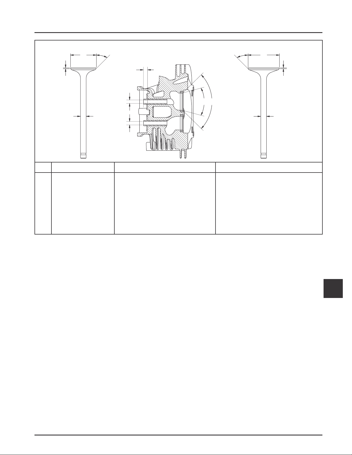
Section 9
Inspection and Reconditioning
EXHAUST V ALVE
G
H
Dimension
A
Seat Angle
B
Seat Taper
C
Guide Depth
D
Guide I.D.
E
Valve Head Diameter
F
Valve Face Angle
G
Valve Margin (Min.)
H
Valve Stem Diameter
INT AKE VAL VE
E
F
C
D
INT
EXH
D
Intake
89°
30°
8.5 mm (0.334 in.)
7.038/7.058 mm (0.2771/0.2779 in.)
38.625/38.685 mm (1.5206/1.5230 in.)
45°
1.0 mm (0.0393 in.)
6.982/7.000 mm (0.2749/0.2756 in.)
AB
89°
30°
8.5 mm (0.334 in.)
7.038/7.058 mm (0.2771/0.2779 in.)
31.625/31.825 mm (1.2450/1.2549 in.)
45°
1.0 mm (0.0393 in.)
6.970/6.988 mm (0.2744/0.2751 in.)
F
E
G
H
Exhaust
Figure 9-6. Valve Details.
Hard starting or loss of power accompanied by high
fuel consumption may be symptoms of faulty valves.
Although these symptoms could also be attributed to
worn rings, remove and check the valves first. After
removal, clean the valve heads, faces, and stems with
a power wire brush.
Then, carefully inspect each valve for defects such as a
warped head, excessive corrosion, or a worn stem end.
Replace valves found to be in bad condition. A normal
valve and valves in bad condition are shown in the
accompanying illustrations.
9
9.5
Page 88

Section 9
Inspection and Reconditioning
Normal: Even after long hours of operation a valve
can be reconditioned and reused if the face and
margin are in good shape. If a valve is worn to where
the margin is less than 1/32" do not reuse it. The valve
shown was in operation for almost 1000 hours under
controlled test conditions.
Bad Condition: The valve depicted here should be
replaced. Note the warped head; margin damaged
and too narrow. These conditions could be attributed
to excessive hours or a combination of poor operating
conditions.
Leakage: A poor grind on face or seat of valve will
allow leakage resulting in a burned valve on one side
only.
Coking: Coking is normal on intake valves and is not
harmful. If the seat is good, the valve could be reused
after cleaning.
9.6
Page 89

Section 9
Inspection and Reconditioning
Excessive Combustion Temperatures: The white
deposits seen here indicate very high combustion
temperatures, usually due to a lean fuel mixture.
Gum: Gum deposits usually result from using stale
gasoline. Gum is a prevalent cause of valve sticking.
The cure is to ream the valve guides and clean or
replace the valves, depending on their condition.
Stem Corrosion: Moisture in fuel or from
condensation are the most common causes of valve
stem corrosion. Condensation occurs from improper
preservation during storage and when engine is
repeatedly stopped before it has a chance to reach
normal operating temperatures. Replace corroded
valves.
9
Overheating: An exhaust valve subject to
overheating will have a dark discoloration in the area
above the valve guide. Worn guides and faulty valve
springs may cause this condition. Also check for
clogged air intake, and blocked fins when this
condition is noted.
9.7
Page 90

Section 9
Inspection and Reconditioning
Valve Guides
If a valve guide is worn beyond specifications, it will
not guide the valve in a straight line. This may result
in burnt valve faces or seats, loss of compression, and
excessive oil consumption.
To check valve guide-to-valve stem clearance,
thoroughly clean the valve guide and, using a splitball gauge, measure the inside diameter of the guide.
Then, using an outside micrometer, measure the
diameter of the valve stem at several points on the
stem where it moves in the valve guide. Use the largest
stem diameter to calculate the clearance by
subtracting the stem diameter from the guide
diameter. If the intake clearance exceeds
0.038/0.076 mm (0.0015/0.0030 in.), or the exhaust
clearance exceeds 0.050/0.088 mm (0.0020/0.0035 in.),
determine whether the valve stem or guide is
responsible for the excessive clearance.
The maximum (I.D.) wear on the intake valve guide is
7.135 mm (0.2809 in.) while 7.159 mm (0.2819 in.) is
the maximum allowed on the exhaust guide. The
guides are not removable but can be reamed 0.25 mm
(0.010 in.) oversize. Valves with 0.25 mm oversize
stems must then be used.
If the guides are within limits but the valve stems are
worn beyond limits, install new valves.
Valve Seat Inserts
Hardened steel alloy intake and exhaust valve seat
inserts are press fitted into the cylinder head. The
inserts are not replaceable but can be reconditioned if
not too badly pitted or distorted. If cracked or badly
warped, the cylinder head should be replaced.
Recondition the valve seat inserts following the
instructions provided with the valve seat cutter being
used. A typical cutter is shown in Figure 9-7. The final
cut should be made with an 89° cutter as specified for
the valve seat angle in Figure 9-6. Cutting the proper
45° valve face angle as specified in Figure 9-6, and the
proper valve seat angle (44.5°, half of the full 89° angle),
will achieve the desired 0.5° (1.0° full cut) interference
angle where the maximum pressure occurs on the
outside diameters of the valve face and seat.
Valve Seat Cutter
Pilot
Figure 9-7. Typical Valve Seat Cutter.
Lapping Valves
Reground or new valves must be lapped in, to
provide proper fit. Use a hand valve grinder with a
suction cup for final lapping. Lightly coat the valve
face with a fine grade of grinding compound, then
rotate the valve on its seat with the grinder. Continue
grinding until a smooth surface is obtained on the
seat and on the valve face. Thoroughly clean the
cylinder head in soap and hot water to remove all
traces of grinding compound. After drying the
cylinder head, apply a light coating of SAE 10 oil to
prevent rusting.
Valve Stem Seals
These engines use valve stem seals on the intake and
exhaust valves. Always use new seals when the
valves are removed from the cylinder head. The seals
should also be replaced if deteriorated or damaged in
any way. Never reuse an old seal.
Pistons and Rings
Inspection
Scuffing and scoring of pistons and cylinder walls
occurs when internal engine temperatures approach
the welding point of the piston. Temperatures high
enough to do this are created by friction, which is
usually attributed to improper lubrication and/or
overheating of the engine.
Normally, very little wear takes place in the piston
boss-piston pin area. If the original piston and
connecting rod can be reused after new rings are
installed, the original pin can also be reused but new
piston pin retainers are required. The piston pin is
included as part of the piston assembly – if the pin
boss in the piston or the pin are worn or damaged, a
new piston assembly is required.
9.8
Page 91

Section 9
Inspection and Reconditioning
Ring failure is usually indicated by excessive oil
consumption and blue exhaust smoke. When rings
fail, oil is allowed to enter the combustion chamber
where it is burned along with the fuel. High oil
consumption can also occur when the piston ring end
gap is incorrect because the ring cannot properly
conform to the cylinder wall under this condition. Oil
control is also lost when ring gaps are not staggered
during installation.
When cylinder temperatures get too high, lacquer
and varnish collect on pistons causing rings to stick,
which results in rapid wear. A worn ring usually
takes on a shiny or bright appearance.
Scratches on rings and pistons are caused by
abrasive material such as carbon, dirt, or pieces of
hard metal.
Detonation damage occurs when a portion of the fuel
charge ignites spontaneously from heat and pressure
shortly after ignition. This creates two flame fronts
which meet and explode to create extreme
hammering pressures on a specific area of the piston.
Detonation generally occurs from using low octane
fuels.
Preignition or ignition of the fuel charge before the
timed spark can cause damage similar to detonation.
Preignition damage is often more severe than
detonation damage. Preignition is caused by a hot
spot in the combustion chamber from sources such as
glowing carbon deposits, blocked cooling fins, an
improperly seated valve, or wrong spark plug(s).
See Figure 9-8 for some common types of piston and
ring damage.
Overheated or Deteriorated Oil
Figure 9-8. Common Types of Piston and Ring Damage.
Abrasive Scratched RingsStuck, Broken Rings
9
Scored Piston and Rings
9.9
Page 92

Section 9
Inspection and Reconditioning
Replacement pistons are available in STD bore size,
and in 0.25 mm (0.010 in.), and 0.50 mm (0.020 in.)
oversize. Replacement pistons include new piston
ring sets and new piston pins.
Replacement ring sets are also available separately
for STD, 0.25 mm (0.010 in.), and 0.50 mm (0.020 in.)
oversize pistons. Always use new piston rings when
installing pistons. Never reuse old rings.
Some important points to remember when servicing
piston rings:
1. The cylinder bore must be deglazed before
service ring sets are used.
2. If the cylinder bore does not need reboring and if
the old piston is within wear limits and free of
score or scuff marks, the old piston may be
reused.
3. Remove the old rings and clean up the grooves.
Never reuse old rings.
4. Before installing the new rings on the piston,
place the top two rings, each in turn, in its
running area in the cylinder bore and check the
end gap. See Figure 9-9. Compare the ring gap to
the specifications listed in Section 1.
Figure 9-10. Measuring Piston Ring Side
Clearance.
Install New Piston Rings
To install new piston rings, proceed as follows:
NOTE: Rings must be installed correctly. Ring
installation instructions are usually included
with new ring sets. Follow instructions
carefully. Use a piston ring expander to
install rings. See Figure 9-11. Install the
bottom (oil control) ring first and the top
compression ring last. Refer to Figure 9-12.
Piston Ring
Figure 9-9. Measuring Piston Ring End Gap.
5. After installing the new compression (top and
middle) rings on the piston, check the piston-toring side clearance. Compare the clearance to
specifications listed in Section 1. If the side
clearance is greater than specified, a new piston
must be used. Refer to Figure 9-10.
9.10
Piston Ring
Expander
Figure 9-11. Inst alling Piston Rings.
Page 93

Section 9
Inspection and Reconditioning
Piston Ring
End Gap
Identification
Mark
Piston
T op Compression
Ring
Center Compression
Ring
Rails
Oil Control Ring
(Three Piece)
Figure 9-12. Piston Ring Installation.
1. Oil Control Ring (Bottom Groove): Install the
expander and then the rails. Make sure the ends
of expander are not overlapped.
Expander
Service replacement connecting rods are available in
STD crankpin size and 0.25 mm (0.010 in.) undersize.
Always refer to the appropriate parts information to
ensure that correct replacements are used.
Hydraulic Lifters
Inspection
Check the base surface of the hydraulic lifters for
wear or damage. If the lifters need to be replaced,
apply a liberal coating of Kohler lubricant (see
Section 2) to the base of each new lifter before it is
installed.
“Bleeding” the Lifters
To prevent a possible bent push rod or broken rocker
arm, it is important to “bleed” any excess oil out of
the lifters before they are installed.
1. Cut a 50-75 mm (2-3 in.) piece from the end of an
old push rod and chuck it in a drill press.
2. Lay a rag or shop towel on the table of the drill
press and place the lifter, open end up, on the
towel.
3. Lower the chucked push rod until it contacts the
plunger in the lifter. Slowly “pump” the plunger
two or three times to force the oil out of the feed
hole in the side of the lifter.
2. Middle Compression Ring (Center Groove):
Install the center ring using a piston ring
installation tool. Make sure the identification
mark is up or the dykem stripe (if contained), is
to the left of the end gap.
3. Top Compression Ring (Top Groove): Install the
top ring using a piston ring expander. Make sure
the identification mark is up or the dykem stripe
(if contained), is to the left of the end gap.
Connecting Rods
Offset, stepped-cap connecting rods are used in these
engines.
Inspection and Service
Check the bearing area (big end) for excessive wear,
score marks, running and side clearances (refer to
Section 1, Specifications, Tolerances, and Special
Torque Values). Replace the rod and cap if scored or
excessively worn.
Governor Gear Assembly
Inspection
The governor gear is located within the crankcase.
Inspect the governor gear teeth. Replace the gear if it
is worn, chipped, or if any teeth are missing. Inspect
the governor weights. They should move freely in the
governor gear.
Disassembly
The governor gear must be replaced once it is
removed from the crankcase.
NOTE: The governor gear is held onto the shaft by
small molded tabs in the gear. When the gear
is removed from the shaft these tabs are
destroyed and the gear must be replaced.
Therefore, remove the gear only if absolutely
necessary.
9
9.11
Page 94

Section 9
Inspection and Reconditioning
Closure Plate Assembly
Inspection
Inspect the oil seal in the closure plate and remove it if
it is worn or damaged. Refer to Install Closure Plate
Oil Seal in Section 10 for new oil seal installation.
Inspect the main bearing surface for wear or damage
(refer to Section 1, Specifications, Tolerances, and
Special Torque Values). Replace the bearing or closure
plate assembly if required.
Oil Pump Assembly
Disassembly
1. Remove the three hex flange screws securing the
oil pump housing including the relief valve
baffle, and the single screw with clamp for the
pickup tube. See Figure 9-13.
2. Remove the oil pump housing and pickup tube
from the closure plate.
3. Remove the oil pump gerotor gears from the
closure plate recess.
Inspection
Inspect the oil pump housing, gerotor gears, and
closure plate recess for nicks, burrs, wear, or any
visible damage. Inspect the inlet seal for the pickup
tube in the housing. If any parts are worn or
damaged, replace the seal, oil pump or closure plate
as required.
Reassembly
1. Make sure the recess in the closure plate for the
oil pump gerotor gears is clean.
2. Lubricate the oil pump gerotor gears with grease
(Lubriplate
the recess. See Figure 9-14.
®
100 or equivalent), and install into
4. Remove the oil pickup by pulling it free from the
oil pump body.
5. The relief valve is a one-piece style, staked to the
oil pump housing; removal should not be
attempted, nor is internal servicing possible. If a
problem with the relief valve is encountered, the
oil pump should be replaced. See Figure 9-15.
Mounting
Screws
Oil
Pump
Pickup
Tube
Figure 9-13. Removing Oil Pump.
Relief
Valve
Baffle
Figure 9-14. Installing and Lubricating Oil Pump
Gerotor Gears.
3. Lightly lubricate with oil and install the inlet
seal into the oil pump housing until it is fully
seated. See Figure 9-15.
Inlet
Seal
Relief
Valve
9.12
Figure 9-15. Installing Inlet Seal in Oil Pump
Housing.
Page 95

Section 9
Inspection and Reconditioning
4. Install the O-Ring in the groove of the oil pump
housing. Use a small quantity of grease to hold it
in place. See Figure 9-16.
O-Ring
Figure 9-16. O-Ring Installed in Oil Pump Housing.
5. Lightly lubricate the I.D. of the inlet seal with oil
and carefully insert the ferruled end of the
pickup tube through the grommet, into the oil
pump housing. Position the pickup tube so the
outboard end faces up. See Figure 9-17.
7. Install the clamp for the pickup tube and finger
tighten the screw. Check the alignment of the
parts and torque the oil pump housing screws as
specified using the sequence shown in Figure
9-18.
Torque the hex flange screws as follows:
a. Install fastener into location No. 1 and
lightly tighten to position the pump.
b. Install fastener into location No. 2 and
fully torque to the recommended value.
c. Install fastener into location No. 3 and
fully torque to the recommended value.
d. Finish torquing fastener in location No. 1
to the recommended value.
First Time Installation: 10.7 N·m (95 in. lb.)
All Reinstallations: 6.7 N·m (60 in. lb.)
3
6. Install the oil pump housing with the pickup
tube, over the oil pump boss and gears. Position
the relief valve baffle on screws 2 and 3. See
Figure 9-18. Align the three screw hole locations.
Mounting
Screws
Oil
Pump
Pickup
Tube
Figure 9-17. Installed Oil Pump and Pickup Tube.
Relief
Valve
Baffle
Pickup
Tube
Clamp
and
Screw
1
4
2
Figure 9-18. Oil Pump Screws Torque Sequence.
8. Torque the clamp (pickup tube) mounting screw
to 10.7 N·m (95 in. lb.) into a new hole, or 7.3
N·m (65 in. lb.) into a used hole. See Figure 9-17.
9
9.13
Page 96

Section 10
Reassembly
Section 10
Reassembly
General
NOTE: Make sure the engine is assembled using all
specified torque values, tightening sequences,
and clearances. Failure to observe
specifications could cause severe engine wear
or damage. Always use new gaskets. Apply a
small amount of oil to the threads of critical
fasteners before assembly, unless a Sealant or
Loctite® is specified or preapplied.
Make sure all traces of any cleaner are removed before
the engine is assembled and placed into operation.
Even small amounts of these cleaners can quickly
break down the lubricating properties of engine oil.
Check the closure plate, crankcase, cylinder heads,
and valve covers to be certain that all of the old
gasket material has been removed. Use gasket
remover, lacquer thinner, or paint remover to remove
any remaining traces. Clean the surfaces with
isopropyl alcohol, acetone, lacquer thinner, or
electrical contact cleaner.
Typical Reassembly Sequence
The following sequence is suggested for complete
engine reassembly. This procedure assumes that all
components are new or have been reconditioned, and
all component subassembly work has been
completed. The sequence may vary to accommodate
options or special equipment. Detailed procedures
follow:
16. Install push rods and rocker arms.
17. Install valve covers.
18. Install spark plugs.
19. Install oil filter adapter.
20. Install intake manifold.
21. Install oil filter housing assembly.
22. Install backing shroud assembly.
23. Install stator, wiring harness, and rectifierregulator.
24. Install flywheel.
25. Install ignition modules.
26. Install outer cylinder baffles.
27. Install oil cooler.
28. Install cooling fan and grass screen.
29. Install electric starter.
30. Install valley baffles.
31. Install carburetor
32. Install governor lever.
33. Install control bracket and air cleaner assembly.
34. Install throttle and choke linkages.
35. Install Oil Sentry™switch (if equipped).
36. Install blower housing and cylinder shrouds.
37. Install control panel (if equipped).
38. Install muffler.
39. Install oil filter and add oil to crankcase.
40. Connect spark plug leads.
Install Flywheel End Oil Seal
1. Make sure that the seal bore of the crankcase is
clean and free of any nicks or burrs. See Figure
10-1.
10
1. Install flywheel end oil seal.
2. Install lifter feed chamber gaskets and cover.
3. Install flywheel end main bearing.
4. Install governor shafts, seal, and governor gear.
5. Install crankshaft.
6. Install connecting rods with pistons and rings.
7. Install camshaft.
8. Install closure plate main bearing and oil seal.
9. Install closure plate assembly.
10. Install oil pickup screen.
11. Install oil reservoir.
12. Check crankshaft end play.
13. Install breather assembly.
14. Install hydraulic lifters.
15. Assemble and install cylinder heads.
Figure 10-1. Seal Bore of Crankcase.
10.1
Page 97

Section 10
Reassembly
2. Apply a light coat of clean engine oil to the
outside diameter of the oil seal.
3. Install the oil seal into the crankcase using a seal
driver. Make sure the oil seal is installed straight
and true in the bore and that the tool bottoms
against the crankcase. See Figures 10-2 and 10-3.
Figure 10-2. Installing Oil Seal with Driver.
Mounting
Screws
Baffle (Used on Some
Models Only)
Lifter
Feed
Chamber
Figure 10-4. Lifter Feed Chamber Assembly
Details.
Cover
Gasket
Install Flywheel End Main Bearing
If the flywheel end main bearing was removed in
servicing, install a new bearing using an arbor press
and driver.
1. Make sure the crankcase bore for the main
bearing is clean, dry and free of nicks or burrs.
Figure 10-3. Installed Flywheel End Oil Seal.
Install Lifter Feed Chamber Gaskets and
Cover
1. Install the lifter feed chamber gasket, followed by
the lifter feed cover over the lifter feed chamber. If
used, position the breather baffle on top of the
parts with the winged offset down.
2. Install the three screws. Make sure all the parts
are properly aligned. Torque the screws to 6.2
N·m (55 in. lb.) into new holes, or 4.0 N·m
(35 in. lb.), into used holes. See Figure 10-4.
2. Press the flywheel side main bearing in place
with the notch oriented in the 12 o’clock position
using an arbor press and driver. See Figure 10-5.
Make sure the bearing is fully seated against the
flange and the oil feed hole is open in the
crankcase. See Figure 10-6.
3. Apply a light coat of clean engine oil to the inner
surface of the main bearing.
Figure 10-5. Installing Main Bearing.
10.2
Page 98

Notch
Main
Bearing
Figure 10-6. Installed Main Bearing.
Install Governor Shafts, Seal, and
Governor Gear
If the governor shafts, seal, and/or governor gear were
removed, reassemble as follows.
Section 10
Reassembly
2. If the governor gear shaft was removed, press or
lightly tap the replacement shaft into the closure
plate to depth shown in Figure 10-10.
Governor
Gear Shaft
Figure 10-9. Installed Governor Gear Shaft.
1. Lightly oil the lip and outside diameter of the
new governor cross shaft seal. Install the seal
into the crankcase to the depth shown in Figure
10-8.
Seal
Figure 10-7. Installing Governor Cross Shaft Seal.
Seal depth
1.5-2.0 mm (0.059-0.078 in.)
12.66 mm
(0.498 in.)
Crankcase
Surface
Figure 10-10. Governor Gear Shaft Press Depth.
3. Lubricate the governor cross shaft bearing
surfaces in the crankcase with engine oil. Insert
the end with the flat for the governor gear yoke
into the crankcase first and position so the flat is
up. See Figure 10-11.
Governor
Cross Shaft
Governor
Gear Shaft
10
Crankcase
Surface
Oil Seal
Figure 10-8. Governor Shaft Seal Depth.
Figure 10-11. Inst alling Governor Cross Shaft.
10.3
Page 99

Section 10
Reassembly
4. Attach the governor yoke to the cross shaft so the
curved section is up as marked. Secure with the
two screws. If a thread locking compound is not
preapplied, apply a small amount of Loctite
No. 266 or equivalent, to the screw threads
before installing. Torque the screws to 2.2 N·m
(20 in. lb.). See Figure 10-12.
®
Governor
Gear
Assembly
Figure 10-14. Installing Governor Gear Assembly .
Figure 10-12. Installed Governor Yoke.
5. Install the first regulating pin with the head
down so it will contact the yoke. Install the
governor gear with the second regulating pin
and the flyweight assembly in/down onto the
governor shaft until it locks into position. Apply
a small amount of grease to the locking tab
thrust washer and install on top of the governor
gear so the tang is facing up in the 6 o’clock
position. See Figures 10-13, 10-14, and 10-15.
Second
Regulating
Pin
Governor
Gear
First
Regulating
Pin
Figure 10-13. Regulating Pins and Governor Gear.
Tab
Position
Figure 10-15. Installed Locking Tab Washer.
Install Crankshaft
1. Carefully slide the flywheel end of the crankshaft
through the main bearing in the crankcase. See
Figure 10-16.
10.4
Figure 10-16. Installing Crankshaft.
Page 100

Install Connecting Rods with Pistons and
Rings
NOTE: The cylinders are numbered on the
crankcase. Make sure to install the piston,
connecting rod and end cap into the
appropriate cylinder bore as previously
marked at disassembly. Do not mix the end
caps and connecting rods.
NOTE: Proper orientation of the piston/connecting
rod assemblies inside the engine is extremely
important. Improper orientation can cause
extensive wear or damage. Be certain the
pistons and connecting rods are assembled
exactly as shown in Figure 10-17.
Section 10
Reassembly
Figure 10-18. FL Y Mark on Piston.
No. 1 Side
Figure 10-17. Piston and Connecting Rod
Orientation.
1. Stagger the piston rings in the grooves until the
end gaps are 120° apart. The oil ring rails should
also be staggered.
2. Lubricate the cylinder bore, piston, and piston
rings with engine oil. Compress the rings of the
#1 piston using a piston ring compressor.
3. Lubricate the crankshaft journals and connecting
rod bearing surfaces with engine oil.
4. Make sure the FLY stamping on the piston is
facing toward the flywheel side of the engine. See
Figure 10-18. Use a hammer with a rubber grip
and gently tap the piston into the cylinder as
shown in Figure 10-19. Be careful that the oil ring
rails do not spring free between the bottom of the
ring compressor and top of the cylinder.
No. 2 Side
Figure 10-19. Installing Piston Assembly Using Ring
Compressor T ool.
5. Install the inner rod cap to the connecting rod
using the two hex flange screws. Torque the
screws in increments to 11.3 N·m (100 in. lb.).
Illustrated instructions are provided in the
service rod package. See Figure 10-20.
NOTE: Align the chamfer of the connecting rod
with the chamfer of its mating end cap.
When installed, the flat faces of the
connecting rods should face each other.
The faces with the raised rib should be
toward the outside.
10
Figure 10-20. T orquing Connecting Rod End Cap
Screws.
10.5
 Loading...