

Page 1

Operation and
Installation Manual
Marine Generator Sets
Models:
3.5CFZ
4CZ
5CFZ
6.5CZ
TP-5695 12/93
Page 2

California Proposition 65
WARNING
Engine exhaust from this product contains
chemicalsknowntotheState of Californiato cause
cancer, birth defects, or other reproductive harm.
Page 3

Table of Contents
SUBJECT PAGE SUBJECT PAGE
Safety Precautions and Instructions i. . . . . . .
Reference Material viii. . . . . . . . . . . . . . . . . . . . . . .
Routine Service Parts x. . . .. . . .. . . .. . . .. . . .. .
Glossary of Abbreviations xi. . . . . . . . . . . . . . . .
Section 1. Specifications 1-1. . . . . . . . . . . . . . . . . .
Introduction 1-1. . . .. . . .. . . .. . . .. . . .. . . .. . . .. . .
Specifications 1-1. . . .. . . .. . . .. . . .. . . .. . . .. . . ..
General Specifications 1-1. . . .. . . .. . . .. . . .. . .
Generator 1-2. . . .. . . .. . . .. . . .. . . .. . . .. . . .. .
Engine 1-3. . . .. . . .. . . .. . . .. . . .. . . .. . . .. . . ..
Accessories 1-5. . . .. . . .. . . .. . . .. . . .. . . .. . . .. .
Service Views 1-6. . . .. . . .. . . .. . . .. . . .. . . .. . . ..
Section 2. Operation 2-1. . . . . . . . . . . . . . . . . . . . . .
Prestart Checks 2-1. . . .. . . .. . . .. . . .. . . .. . . .. . .
Controller 2-2. . . .. . . .. . . .. . . .. . . .. . . .. . . .. . . .
Starting 2-3. . . .. . . .. . . .. . . .. . . .. . . .. . . .. . . .. .
Stopping 2-3. . . .. . . .. . . .. . . .. . . .. . . .. . . .. . . ..
Circuit Protection 2-4. . . .. . . .. . . .. . . .. . . .. . . .. .
Engine Safety Shutdown Switches 2-4. . . .. . . .. . .
Remote Panels (Optional) 2-6.. . . . . . . . . . . . . . . . .
Section 3. Scheduled Maintenance 3-1. . . . . . . . .
Service Schedule 3-2. . . .. . . .. . . .. . . .. . . .. . . .. .
Lubrication System 3-4. . . .. . . .. . . .. . . .. . . .. . . .
Specifications 3-4. . . .. . . .. . . .. . . .. . . .. . . .. . .
Oil Check 3-4.. . . . . . . . . . . . . . . . . . . . . . . . . . . . .
Adding Oil 3-5. . . .. . . .. . . .. . . .. . . .. . . .. . . .. .
Oil Change/Oil Filter Change 3-5. . . .. . . .. . . .. .
Fuel System 3-6. . . . . . . . . . . . . . . . . . . . . . . . . . . . . .
Specifications 3-6. . . .. . . .. . . .. . . .. . . .. . . .. . .
Fuel Pump Screen 3-7. . . .. . . .. . . .. . . .. . . .. . .
Carburetor/Choke Lubrication 3-8. . . .. . . .. . . ..
Carburetor Adjustments 3-8.. . . . . . . . . . . . . . . . .
Ignition System 3-9. . . .. . . .. . . .. . . .. . . .. . . .. . . .
Ignition System Service 3-9. . . .. . . .. . . .. . . .. .
Spark Plugs 3-9. . . .. . . .. . . .. . . .. . . .. . . .. . . .
Cooling Systems—Closed/Heat Exchanger 3-12. . .
Filling and Checking 3-12. . . .. . . .. . . .. . . .. . . ..
Flushing and Cleaning 3-14. . . .. . . .. . . .. . . .. . .
Anticorrosion Zinc 3-16. . .. . . .. . . .. . . .. . . .. . . .
Pressure Cap 3-17. . . . . . . . . . . . . . . . . . . . . . . . . . .
Siphon Break 3-17.. . . .. . . .. . . .. . . .. . . .. . . .. .
Air Cleaner and Mixing Elbow 3-17. . . .. . . .. . . .. . .
Servicing Air Cleaner 3-17. . . .. . . .. . . .. . . .. . . .
Servicing Mixing Elbow 3-17.. .. . . .. . . .. . . .. . . .
Battery 3-18. . . .. . . .. . . .. . . .. . . .. . . .. . . .. . . .. . .
Cleaning 3-18. . .. . . .. . . .. . . .. . . .. . . .. . . .. . . .
Checking Electrolyte Level 3-18. . . .. . . .. . . .. . . .
Checking Specific Gravity 3-18. . . .. . . .. . . .. . . .
Charging 3-19. . . . . . . . . . . . . . . . . . . . . . . . . . . . . . .
Valve Adjustment 3-20. . . .. . . .. . . .. . . .. . . .. . . .. .
Governor 3-22. . . .. . . .. . . .. . . .. . . .. . . .. . . .. . . ..
Lubrication 3-22.. . . .. . . .. . . .. . . .. . . .. . . .. . . .
Governor Adjustment 3-22. . . . . . . . . . . . . . . . . . . .
Wattage Requirements 3-23. . . .. . . .. . . .. . . .. . . ..
Generator Service 3-23. . . .. . . .. . . .. . . .. . . .. . . ..
General 3-23. . .. . . .. . . .. . . .. . . .. . . .. . . .. . . ..
Storage Procedure 3-24. . . .. . . .. . . .. . . .. . . .. . . .
Section 4. Troubleshooting 4-1. . . . . . . . . . . . . . . .
Engine 4-1. . . .. . . .. . . .. . . .. . . .. . . .. . . .. . . .. . .
Electrical System 4-3.. . . . . . . . . . . . . . . . . . . . . . . . .
Generator 4-4. . . .. . . .. . . .. . . .. . . .. . . .. . . .. . . .
Section 5. Wiring Diagrams 5-1.. . . . . . . . . . . . . .
Section 6. Installation 6-1. . . . . . . . . . . . . . . . . . . . .
Introduction 6-1. . . .. . . .. . . .. . . .. . . .. . . .. . . .. . .
Generator Selection and
Wattage Requirements 6-1. . . .. . . .. . . .. . . .. . . ..
Lighting Load 6-1. . . .. . . .. . . .. . . .. . . .. . . .. . .
Motor Loads 6-1. . . .. . . .. . . .. . . .. . . .. . . .. . . .
Appliance Loads 6-2. . . . . . . . . . . . . . . . . . . . . . . .
Kilowatt Derating 6-2. . . . . . . . . . . . . . . . . . . . . . . .
Location 6-4.. .. . . .. . . .. . . .. . . .. . . .. . . .. . . .. . .
General 6-4. . . .. . . .. . . .. . . .. . . .. . . .. . . .. . . .
Space 6-4. . . . . . . . . . . . . . . . . . . . . . . . . . . . . . . . .
Mounting 6-4. . . . . . . . . . . . . . . . . . . . . . . . . . . . . . .
Ventilation 6-4. . . .. . . .. . . .. . . .. . . .. . . .. . . .. . . .
Fuel Systems 6-5. . . . . . . . . . . . . . . . . . . . . . . . . . . . .
Fuel Supply 6-5. . . .. . . .. . . .. . . .. . . .. . . .. . . .
Anti-Siphon Provisions 6-6.. .. . . .. . . .. . . .. . . .
Fuel Lines 6-6. . . . . . . . . . . . . . . . . . . . . . . . . . . . . .
Fuel Pump Lift Capabilities and
Fuel Consumption 6-6. . . .. . . .. . . .. . . .. . . .. . .
Cooling Systems 6-7. . . .. . . .. . . .. . . .. . . .. . . .. .
General 6-7. . . .. . . .. . . .. . . .. . . .. . . .. . . .. . . .
Closed/Heat Exchanger 6-8. . . . . . . . . . . . . . . . . .
Exhaust Systems 6-9. . . . . . . . . . . . . . . . . . . . . . . . . .
General 6-9. . . .. . . .. . . .. . . .. . . .. . . .. . . .. . . .
Above Waterline 6-11. . . . . . . . . . . . . . . . . . . . . . . .
Mid/Below Waterline 6-11.. .. . . .. . . .. . . .. . . .. .
Electrical Systems 6-12. . .. . . .. . . .. . . .. . . .. . . .. .
AC Voltage Connections 6-12. . . . . . . . . . . . . . . . . .
Installation in Steel or Aluminum Vessels 6-12.. .
Battery 6-13. . . .. . . .. . . .. . . .. . . .. . . .. . . .. . . ..
Wiring 6-13. .. . . .. . . .. . . .. . . .. . . .. . . .. . . .. . .
Remote Start Switch Connection 6-14. . . .. . . .. .
Section 7. Installation Drawings 7-1. . . . . . . . . . .
Section 8. Parts Ordering Instructions 8-1. . . . .
Section 9. Operating Hour Service Log 9-1. . . . .
TP-5695 12/93 Table of Contents
Page 4
Safety Precautions and Instructions
A generator set, like any other electro-mechanical
device, can pose potential dangers to life and limb if
improperly maintained or imprudently operated. The
best way to prevent accidents is to be aware of the
potential dangers and to always use good common
sense. In the interest of safety, some general
precautions relating to the operation of a generator set
follow. Keep these in mind. This manual contains
several types of safety precautions which areexplained
below.
DANGER
Dangerisusedtoindicatethepresenceofahazardthat
will cause severe personal injury, death, or substantial
property damage if the warning is ignored.
WARNING
Warning is used to indicate the presence of a hazard
that can cause severe personal injury, death, or
substantial property damage if the warning is ignored.
CAUTION
Cautionis used to indicate thepresence of a hazardthat
will or can cause minor personal injury or property
damage if the warning is ignored.
Safety decals are affixed to the generator set in
prominent places to advise the operator or service
technician of potentially hazardous situations. The
decals are reproduced here to improve operator
recognition and thereby increase decal effectiveness.
Forafurtherexplanation of decal information, reference
theaccompanying safety precautions. Before operating
or servicing the generator set, be sure you understand
the message of these decals. Replacedecals if missing
or damaged.
NOTE
Noteis used to notify people ofinstallation,operation,or
maintenance information that is important but not
hazard-related.
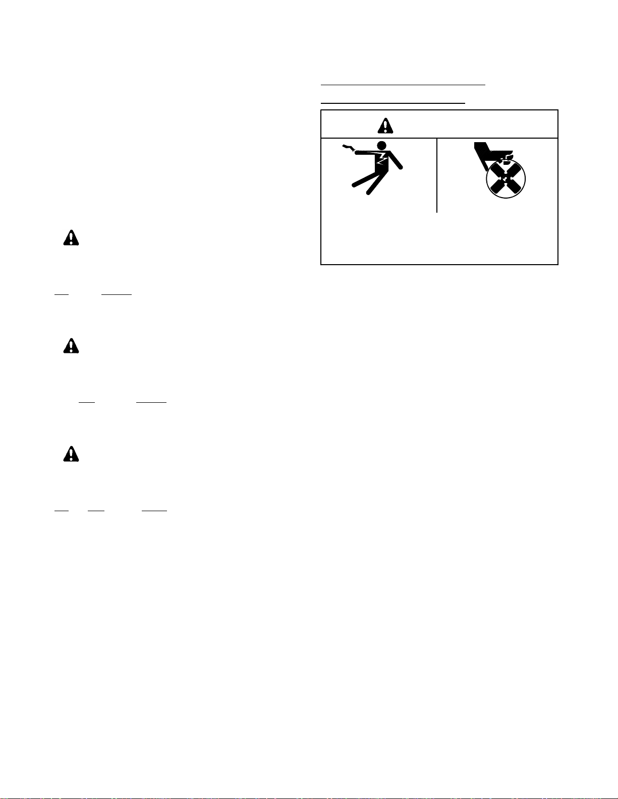
HAZARDOUS VOLTAGE/
ELECTRICAL SHOCK
WARNING
Hazardous voltage.
Can cause severe injury or death.
Do not operate generator set without all guards
and electrical enclosures in place.
Hazardous voltage can cause severe injury or
death. Wherever electricity is present, there is the
hazardof electrocution. Take thesameprecautionswith
electrical appliances in your craft that you would
observe in your home. Open main circuit breaker on all
power sources before servicing equipment. Make sure
unqualified persons, especially children, cannot gain
access to your set—keep thecompartment door locked
orsecurely latched at all times.Besure that generator is
properly grounded. Never touch electrical leads or
appliances with wet hands, when standing in water, or
on wet ground as the chance of electrocution is
especially prevalent under such conditions.
Hazardous voltage can cause severe injury or
death. Use caution when handling the capacitor;
possible electrical shock can result. Discharge
capacitor by shorting terminals together.
Hazardous voltage can cause severe injury or
death. Short circuits can cause bodily injury and/or
equipment damage. Do not contact electrical
connections with tools or jewelry while adjustments are
made. Remove wristwatch, rings, and jewelry that can
cause short circuits.
Hazardous “backfeed” voltage can cause severe
injury or death. Donot connect to anybuilding/marina
electrical system without connecting through an
approved device and afterbuilding mainswitch is open.
Backfeedconnections can causeseriousinjury or death
to utility personnel working to repair a power outage
and/or personnel in the vicinity. Unauthorized
connection may be unlawful in some states and/or
localities. A ship-to-shore transfer switch must be
installed to prevent interconnection of generator set
power and shore power.
Moving rotor.
TP-5695 12/93 Safety Precautions and Instructions i
Page 5
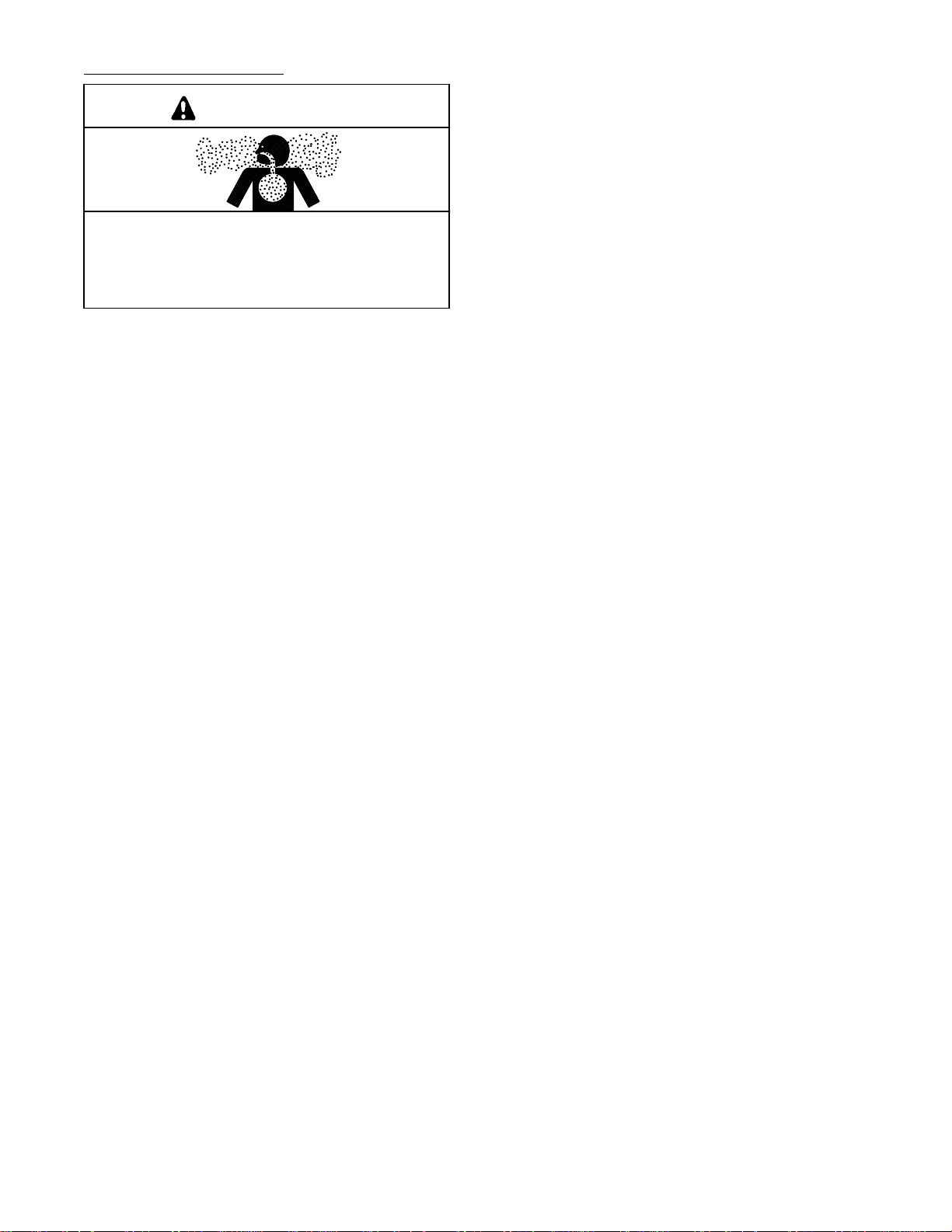
EXHAUST SYSTEM
WARNING
Carbon monoxide.
Can cause severe nausea, fainting, or death.
The exhaust system must be leakproof and
routinely inspected.
Carbon monoxide can cause severe nausea,
fainting, or death. Use the following precautions when
installing and operating generator set. Carbon
monoxide is particularly threatening in that it is an
odorless, colorless, tasteless, nonirritating gas. Be
especially careful if operating the generator when
moored or anchored under calm conditions as gases
may accumulate. If operating the set dockside, moor
yourcraftsothatthe exhaust discharges on the lee side
(the side sheltered from the wind), and always be
mindful of others—make sure your exhaust is directed
away from other boats and occupied buildings. Do not
install exhaust outlet where exhaust can be drawn
through portholes, vents, or air conditioners. If
generator set’s exhaust discharge hole is near to your
craft’swater line, DO NOTOVERLOAD CRAFT so asto
close or restrict exhaust discharge hole.
Carbon monoxide can cause severe nausea,
fainting, or death. In addition to routine inspection of
theexhaust system,acarbon monoxidedetectorshould
be considered. Consult your boat builder or marina for
installation of approved detectors. It is essential that all
detectors be routinely inspected for proper operation.
TP-5695 12/93ii Safety Precautions and Instructions
Page 6
BATTER Y
WARNING
Sulfuric acid in batteries.
Can cause severe injury or death.
Use protective goggles and clothes. Can cause
permanent damage to eyes, burn skin, and eat holes
in clothing.
Sulfuric acid in batteries can cause severe injury or
death. Sulfuric acid in battery can cause permanent
damage to eyes, burn skin, and eat holes in clothing.
Alwayswearsplash-proof safety goggles when working
around the battery. If battery electrolyte is splashed in
the eyes or on skin, immediately flush the affected area
for15 minutes with large quantities of clean water.In the
caseofeyecontact,seek immediate medical aid. Never
addacid toabattery oncethebattery hasbeenplaced in
service. Doing so may result in hazardous spattering of
electrolyte.
Explosion can cause severe injury ordeath. Battery
gases can cause an explosion. Do not smoke or permit
flame or spark to occur near a battery at any time,
particularly when it is being charged. Avoid contacting
terminalswith tools, etc. to prevent burns and toprevent
sparks that could cause an explosion. Remove
wristwatch,rings,andanyotherjewelry before handling
battery. Never connect negative (--) battery cable to
positive (+) connection terminal of starter solenoid. Do
not test battery condition by shorting terminals together
or sparks could ignite battery gases or fuel vapors. Any
compartment containing batteries must be well
ventilated to prevent accumulation of explosive gases.
To avoid sparks, do not disturb battery charger
connections while battery is being charged and always
turn charger off before disconnecting battery
connections. When disconnecting battery, remove
negative lead first and reconnect it last.
TP-5695 12/93 Safety Precautions and Instructions iii
Page 7
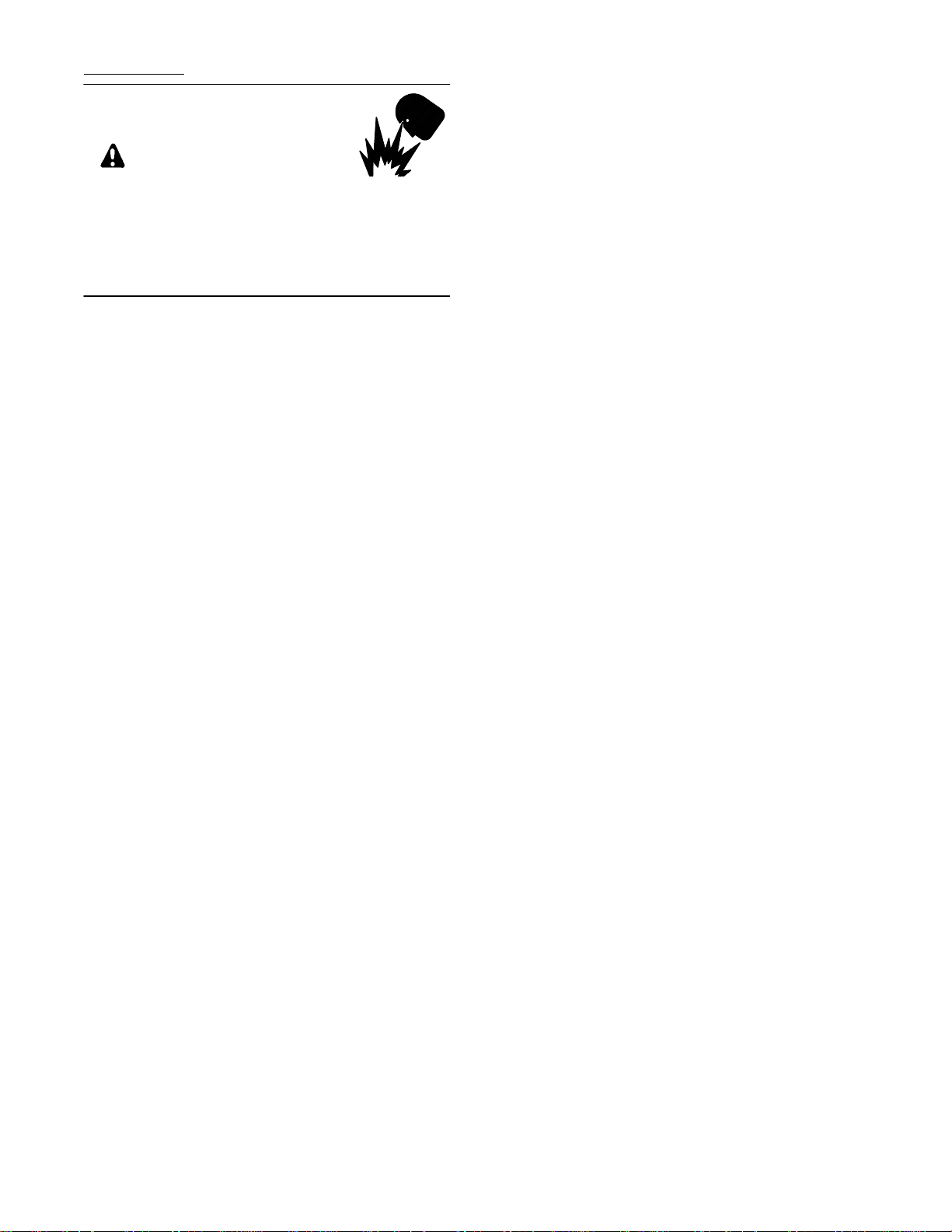
FUEL SYSTEM
WARNING
Explosive fuel vapors can cause severe injury or
death. Additional precautions must be taken when
using the following fuels:
Gasoline—Store gasoline only in approved red
containers clearly marked GASOLINE. Do not store
gasoline in any occupied building.
Explosion.
Gasoline vapors can cause explosion and
severe injury or death.
Before starting generator set, operate blower 4
minutes and check engine compartment for
gasoline vapors.
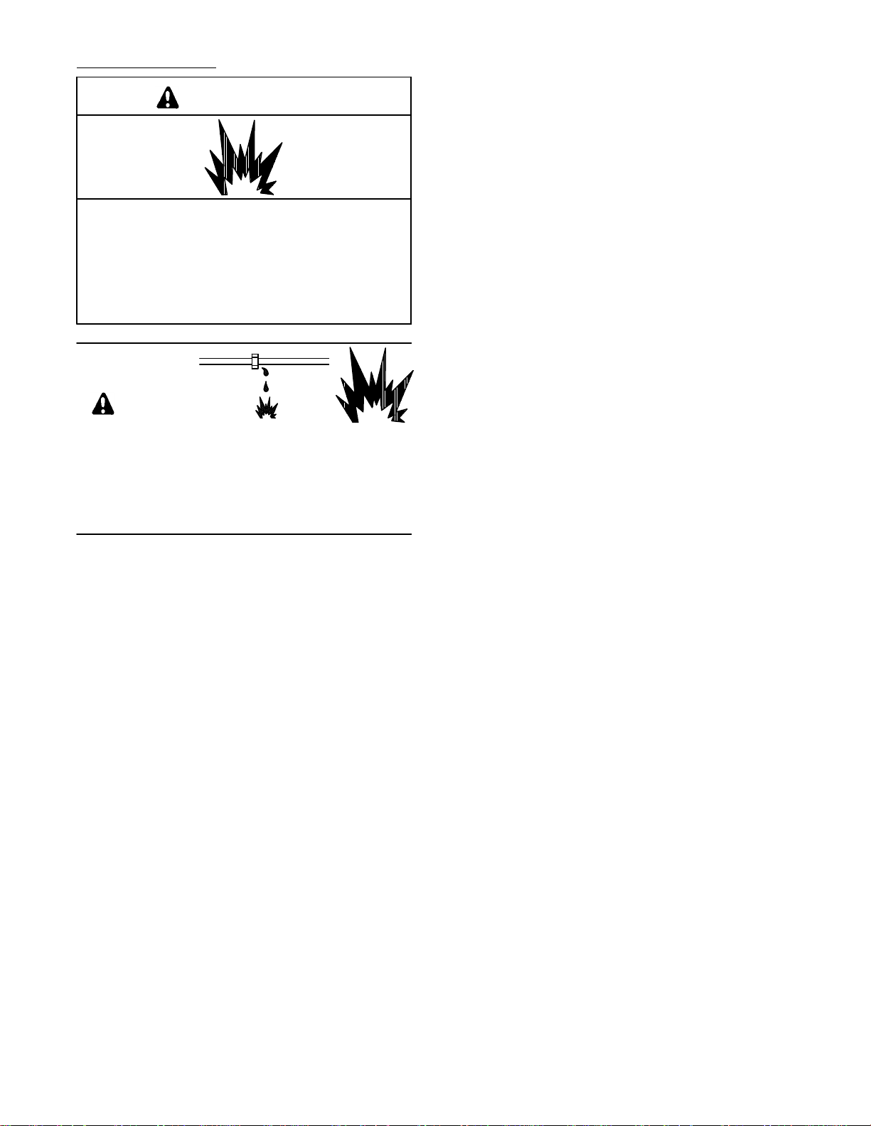
WARNING
Explosive fuel vapors.
Can cause severe injury or death.
Useextreme care when handling, storing,
and using fuels.
Explosive fuel vapors can cause severe injury or
death.Allfuelsarehighlyexplosiveinavapor state.Use
extreme care when handling, storing, and using fuels.
Store fuel in a well-ventilated area away from
spark-producing equipment and out of the reach of
children. Never add fuel to the tank while the engine is
running since spilled fuel may ignite on contact with hot
parts or from ignition spark. Do not smoke or permit
flame or spark to occur near potentialsources of spilled
fuelorfuelvapors.Keepfuellinesand connections tight
and in good condition—don’t replace flexible fuel lines
with rigid lines. Flexible sections are used to avoid
breakage due to vibration. Should any fuel leakage, fuel
accumulation, or electrical sparks be noted, DO NOT
OPERATE GENERATOR SET.Have systems repaired
before resuming generator operation.
Explosive fuel vapors can cause severe injury or
death. Gasoline vapors can explode and can cause
death or severe injury. USCG Regulation 33CFR183
requires all electrical devices (ship-to-shore transfer
switch,remotestartpanel, etc.)to be“ignitionprotected”
whenusedinagasoline(gaseous)-fueledenvironment.
These electrical devices are not “ignition protected” and
are not certified to operate in a gasoline
(gaseous)-fueled environment such as engine room or
near fuel tanks. Acceptable locations would be
wheelhouseor otherliving areasshelteredfrom rainand
water splash.
Explosive fuel vapors can cause severe injury or
death. Spilled fuel can cause an explosion. Use a
container to catch fuel when draining fuel system. Wipe
up all spilled fuel after draining system.
Explosive fuel vapors can cause severe injury or
death. Fuel leakage can cause an explosion. Do not
modify the tank or propulsion engine fuel system. Craft
must be equipped with a tank allowing one of the two
pickup arrangements described. Tank and installation
must conform to U.S.C.G. Regulations.
Explosive fuel vapors can cause severe injury or
death. Fuel leakage can cause an explosion. To
prevent fuel leakage, use pipe sealant on all threaded
fittings. Pipe sealant must be suitable for use in marine
applications having oil and gasoline environments.
TP-5695 12/93iv Safety Precautions and Instructions
Page 8
ACCIDENTAL STARTING
WARNING
Exposed moving parts can cause severe injury or
death. Keep hands, feet, hair, clothing, and test leads
away from belts and pulleys when unit is running.
Replace guards, covers, and screens before operating
generator set.
Accidental starting.
Can cause severe injury or death.
Disconnect battery cables before working on
generator set (negative lead first and reconnect it
last).
Accidental starting can cause severe injury or
death. Disconnect battery cables (remove negative
lead first and reconnect it last) to disable generator set
before working on any equipment connected to
generator. The generator set can be started by remote
start/stop switch unless this precaution is followed.
MOVING PARTS
WARNING
Rotating parts.
Can cause severe injury or death.
HOT PARTS
WARNING
Hot engine and exhaust system.
Can cause severe injury or death.
Donotworkongeneratorsetuntilunitis allowed to
cool.
Hot parts can cause severe injury or death. Do not
touchhot engine parts. Anenginegets hot whilerunning
and exhaust system components get extremely hot.
WARNING
Do not operate generator set without all guards,
screens, or covers in place.
Flying projectiles can cause severe injury or death.
Retorque all crankshaft and rotor hardware after
servicing. When making adjustments or servicing
generator set, do not loosen crankshaft hardware or
rotor thru-bolt. If rotating crankshaft manually, direction
should be clockwise only. Turning crankshaft bolt or
rotor thru-bolt counterclockwise can loosen hardware
and result in serious personal injury from hardware or
pulley flying off engine while unit is running.
Exposed moving parts can cause severe injury or
death. Additional Precautions Regarding Sound Shield
Equipped Models:
Some scheduled maintenance procedures require the
generator set to be running while performing service. If
the sound shield has been removed leaving belts and
pulleys exposed, be especially careful of this area.
Hot coolant and steam.
Can cause severe injury or death.
Before removing pressure cap stop generator,
allow to cool and loosen pressure cap to relieve
pressure.
Hot coolant can cause severe injury or death. Allow
engine to cool and release pressure from cooling
system before opening pressure cap. To release
pressure, cover thepressure cap with a thick cloth then
turn it slowly counterclockwise to the first stop. After
pressure has been completely released and the engine
has cooled, remove cap. If generator set is equipped
witha coolantrecoverytank, checkcoolantlevel at tank.
TP-5695 12/93 Safety Precautions and Instructions v
Page 9
ENGINE BACKFIRE/FLASH FIRE
Asudden backfire cancause severeinjury or death.
Do not operate with air cleaner/silencer removed.
WARNING
Fire.
Can cause severe injury or death.
Do not smoke or permit flame or spark to occur
near fuel or fuel system.
A flash fire can cause severe injury or death. Donot
smokeor permitflameor sparktooccur nearcarburetor,
fuel line, fuel filter,fuel pump, or other potential sources
of spilled fuel orfuel vapors. When removing fuel line or
carburetor, use a proper container to catch all fuel.
A suddenbackfire can cause severe injury or death.
Do not operate with backfire flame arrestor removed.
Asudden flashfire cancause severeinjury ordeath.
Donot smokeorpermit flameorspark tooccur nearfuel
system.Keepthecompartmentandgeneratorsetclean
and free of debris to minimize chances of fire. Wipe up
all spilled fuel and engine oil.
HAZARDOUS NOISE
CAUTION
Hazardous noise.
Can cause loss of hearing.
Never operate generator without a muffler or with
faulty exhaust system.
TP-5695 12/93vi Safety Precautions and Instructions
Page 10
NOTES
NOTE
NOTICE
HARDWARE DAMAGE! Engine and generator may
make use of both American Standard and metric
hardware. Be sure to use the correct size tools to
prevent rounding of bolt heads and nuts.
NOTE
Special attention should be given when checking for
propercoolant level. After the coolanthas been drained,
it normally requires some time before complete refill of
the engine water jacket takes place.
NOTE
When replacing hardware, do not substitute with
inferior grade hardware. Screws and nuts are
available in different hardness ratings. American
Standard hardware uses a series of markings and
metric hardware uses a numeric system to indicate
hardness. Check markings on bolt head and nuts for
proper identification.
This generator set has been rewired from its
nameplate voltage to:
246242
NOTICE
This is a positive terminal only.
Do not attach negative lead!
NOTICE
Checkzinc anode every100 hours or 3months.
NOTICE
NOTE
When a fuse replacement is required, be sure fuse has
the same ampere rating and is the same type (for
example: ABC or 3AB, ceramic). Do not substitute
“clear” glass-type fuses for ceramic fuses. If ampere
rating is unknown orquestionable, see Wiring Diagram.
NOTE
High-mineral content sea water (salt water) can cause
rapid destruction of all metals. Wipe up all salt water
spillage on and around generator set and keep metal
surfaces free from accumulated salt deposits.
Do not use as a step.
Standing on genset could impair operation of unit.
NOTE
Split lock washers may be supplied with some kits. If
split lock washers are supplied with kit, their use is
optional.
TP-5695 12/93 Safety Precautions and Instructions vii
Page 11

Reference Material
It is recommended that the following Regulations and
Standards be followed when installing Marine
Generator Sets.
Pleasure Craft
Designed and manufactured to meet U.S. Coast Guard
Title 33.
U.S. Coast Guard Code of Federal Regulations
Title 33
Subparts I--Electrical Systems
Subparts J--Fuel Systems
Title 46
Subchapter F--Marine Engineering
Part 58--Main and Auxiliary Machinery and Related
Systems
Order the above publications from:
Superintendent of Documents
U.S. Government Printing Office
Washington, DC 20402
1-202-783-3238
Boating Safety Circular Commandant (G-BC)
Boating Statistics (G-BP-1)
U.S. Coast Guard Headquarters
2100 Second Street, S.W.
Washington, DC 20593-0001
Boating Safety Hotline: 1-800-368-5647
Lloyds Registry of Shipping
“Rules for Classification of Ships”
17 Battery Place
New York, N.Y. 10004
212-425-8050
Underwriters Laboratories, Inc. (UL)
Publications Stock
333 Pfingsten Road
Northbrook, IL 60062
Marine Department: 1-919-549-1400
NFPA 302
National Fire Protection Association
60 Batterymarch Park
Quincy, MA 02269
Customer Service
Society of Automotive Engineer’s (SAE)
400 Commonwealth Drive
Warrendale, PA 15096
1-412-776-4970
American Boat and Yacht Council, Inc. (ABYC)
3069 Solomon’s Island Rd.
Edgewater, MD 21037
1-410-956-1050
1-410-974-8112
1-410-956-2737 FAX
American Bureau of Shipping
“Rules for Building and Classing Steel Vessels”
45 Eisenhower Drive
Paramus, N.J. 07652
201-368-9100
IEEE 45
The Institute of Electrical and
Electronics Engineer’s Inc.
345 East 47th Street
New York, NY 10017
TP-5695 12/93viii Reference Material
Page 12

Commercial Vessels
In order to use these generator sets for commercial
applicationswhere U.S. Coast GuardTitle46Certificate
is required, additional modifications will be necessary.
U.S. Coast Guard Code of Federal Regulations
Title 46
Subchapter F--Marine Engineering
Part 58--Main and Auxiliary Machinery and Related
Systems
Subchapter J--Electrical Engineering
Part111--ElectricalSystems--GeneralRequirements
Part 112--Emergency Lighting and Power Systems
Subchapter T--Small Passenger Vessels
(Under 100 Gross Tons)
Part 182--Machinery Installation
Part 183--Electrical Installation
Order the above publications from:
Superintendent of Documents
U.S. Government Printing Office
Washington, DC 20402
1-202-783-3238
American Bureau of Shipping (ABS)
65 Broadway
New York, NY 10006
Order ABS publications from:
American Bureau of Shipping
Book Order Section
45 Eisenhower Drive
P.O. Box 910
Paramus, NJ 97653-0910
Lloyd’s Register of Shipping
71 Fenchurch Street
London, EC3M 4BS England
Midwest Office:
Lloyd’s Register of Shipping
100 South York Street, Room 226
Elmhurst, IL 60126
1-312-279-5414
Additional References
The following organizations provide a service which
may be useful to the generator set installer. These
organizations are not regulatory in nature but rather
provide guidelines and assistance. They are listed only
as a source for additional information. No solicitation or
representation is hereby given.
Yacht Corrosion Consultants, Inc.
2970 Seaborg Ave.
Ventura, CA 93003
1-805-644-1886
Ward’s Marine Electric, Inc.
630 S.W. Flagler Ave.
Ft. Lauderdale, FL 33301
1-305-523-2815
1-800-545-9273
1-305-523-1967 FAX
TP-5695 12/93 Reference Material ix
Page 13

Routine Service Parts
Contact your Kohler generator dealer/distributor for a
complete listing of service parts for your generator set.
Part Description Kohler Part No.
Engine:
Air Filter 278612
Oil Filter 267714
Belt, Timing 267722
Ignition System:
Spark Plug 267713
Sea Water Pump Impeller 229826
Zinc Anode 267928
White Spray Paint 221318
x Routine Service Parts TP-5695 12/93
Page 14

Glossary of Abbreviations
Abbreviations are used throughout this manual. Normally in the text they will appear in complete form with the
abbreviation following in parenthesis the first time they are used. After that they will appear in the abbreviated form.
The commonly used abbreviations are shown below.
Abbreviation Description
AC alternating current
AHWT anticipatory high water temp.
ALOP anticipatory low oil pressure
AM amplitude modulation
Amp ampere
Amps amperes
ANSI American National Standard Institute
API American Petroleum Institute
approx. approximate, approximately
A/R as required, as requested
A/S as supplied, as stated, as suggested
ASA American Standards Association
assy. assembly
ASTM American Society for Testing Materials
ATDC after top dead center
ATS automatic transfer switch
aux. auxiliary
AWG American Wire Gauge
AWM appliance wiring material
bhp brake horsepower
bmep brake mean effective power
Btu British thermal unit
°C Celsius degree
cc cubic centimeter
CCA cold cranking Amps.
CEC Canadian Electrical Code
cfh cubic feet per hour
cfm cubic feet per minute
CID cubic inch displacement
cm centimeter, centimeters
cmm cubic meters per minute
co. company
cont’d. continued
C.S.A. Canadian Standards Association
cu. in. cubic inch, cubic inches
cyl. cylinder
dBA decibels
DC direct current
DCR direct current resistance
deg. degree
dept. department
dia. diameter
e.g. example given
EMI electromagnetic interference
etc. etcetera, (and so forth)
ext. external
°F Fahrenheit degree
fl. oz. fluid ounce, fluid ounces
Abbreviation Description
FM frequency modulation
fs full scale
ft. foot, feet
ft. lbs. foot pound, foot pounds
ga. gauge
gal., gals. gallon, gallons
gal./hr. gallons per hour
gph gallons per hour
gpm gallons per minute
gr. grade
grd. ground
HCHT high cylinder head temperature
HET high exhaust temperature
Hg mercury (element)
H2O water
hp horsepower
hr, hrs hour
HWT high water temperature
Hz hertz (cycles per second)
ID inside diameter
in. inch(es)
inc. incorporated
in. lbs. inch pounds
int. internal
int.-ext. internal-external
ISO International Standards Organization
J joule, joules
JIS Japanese Industry Standard
kg kilogram, kilograms
2
kg/cm
kgm kilogram meter(s)
km kilometer, kilometers
kPa kiloPascal, kiloPascals
kph kilometers per hour
kV kilovolt
kVA kilovolt amperes
kW kilowatt, kilowatts
kWH kilowatt hour
L liter, liters
LxWxH length x width x height
LED, LEDs light emitting diode
lb., lbs. pound, pounds
L/hr. liter per hour, liters per hour
L/min. liter(s) per minutes
LOP low oil pressure
LP liquefied petroleum
LWT low water temperature
m meter, meters
kilograms per square centimeter
TP-5695 12/93 Glossary of Abbreviations xi
Page 15

Abbreviation Description
3
m
cubic meter, cubic meters
max. maximum
MCM one thousand circular mils.
mi. mile, miles
mil one one-thousandth of an inch
min. minimum
mJ millijoule, millijoules
MJ mega joule, mega joules
mm millimeter, millimeters
m3/min cubic meters per minute
MPa megaPascal
mph miles per hour
MS military standard
mW milliwatt, milliwatts
MW megawatt, megawatts
N/A not available
NEC National Electrical Code
NEMA National Electrical
Manufacturers Association
NFPA National Fire Protection Association
Nm Newton meter, Newton meters
no., nos. number, numbers
NPT National Standard taper pipe
thread per general use
N/R not required
OC overcrank
OD outside diameter
OEM original equipment manufacturer
OS overspeed, oversize
OV overvoltage
oz. ounce, ounces
Abbreviation Description
PF power factor
pot. potentiometer
ppm parts per million
psi pounds per square inch
pt., pts. pint, pints
qt., qts. quart, quarts
qty. quantity
ref. reference
RFI radio frequency interference
rms root mean square
rpm revolutions per inch
SAE Society of Automotive Engineers
sec. second, seconds
SCR silicon controlled rectifier
spec, specs specification
sq. square
sq. cm square centimeters
sq. in. square inch, square inches
tach tachometer
TDC top dead center
temp. temperature
TIF telephone influence factor
turbo turbocharger
UNC Unified coarse thread (was NC)
UNF Unified fine thread (was NF)
UL Underwriter’s Laboratories, Inc.
US undersize
V volt, volts
VAC Volts alternating current
VDC volts direct current
W watt, watts
xii Glossary of Abbreviations TP-5695 12/93
Page 16

Section 1. Specifications
Introduction
The craft is equipped with a dependable 110 volt
(reconnectable to 110/220 volt), 50 Hz; or 120 volt
(reconnectable to 120/240 volt), 60 Hz single-phase
alternating current marine generator set. Service
requirements are minimal but are very important to the
safe and efficient operation of the generator set;
therefore, inspect associated parts often. It is
recommended that an authorized service
dealer/distributor perform required servicing to assure
the unit continues to meet U.S.C.G. requirements.
Please take a few moments to read this manual, then
carefullyfollow all service recommendations tokeepthe
set in top condition. Keep this manual aboard the craft
for future reference. See Figure 1-1 for identification
and location of components.
Specifications
General Specifications
3.5CFZ 5CFZ
Dimensions--L x W x H--in. (mm) 27.87 x 17.50 x 16.60
(708 x 445 x 422)
with Sound Shield 31.07 x 18.10 x 17.50
(789 x 460 x 445)
Weight--(wet), lbs. (kg) 208 (94) 231 (104)
with Sound Shield 231 (104) 231 (104)
Air Requirements--cfm (L/min.) 18 (510) 18 (510)
Fuel Consumption U.S. gal./hr. (L/hr.)
Load
25% 0.42 (1.59) 0.44 (1.67)
50% 0.50 (1.89) 0.54 (2.04)
75% 0.59 (2.23) 0.66 (2.50)
100% 0.68 ( 2.57) 0.80 (3.03)
4CZ 6.5CZ
Dimensions--L x W x H --in. (mm) 27.87 x 17.50 x 16.60
(708 x 445 x 422)
with Sound Shield 31.07 x 18.10 x 17.50
(789 x 460 x 445)
Weight--(wet), lbs. (kg) 190 (86) 231 (104)
with Sound Shield 213 (96) 231 (104)
Air Requirements--cfm (L/min.) 18 (510) 18 (510)
Fuel Consumption U.S. gal./hr. (L/hr.)
Load
25% 0.48 (1.81) 0.53 (2.00)
50% 0.55 (2.08) 0.62 (2.34)
75% 0.62 (2.34) 0.86 (3.25)
100% 0.68 (2.57) 1.02 (3.86)
31.07 x 18.10 x 17.50
(789 x 460 x 445)
31.07 x 18.10 x 17.50
(789 x 460 x 445)
31.07 x 18.10 x 17.50
(789 x 460 x 445)
31.07 x 18.10 x 17.50
(789 x 460 x 445)
TP-5695 12/93 Specifications 1-1
Page 17

Generator
3.5CFZ 5CFZ
Rated kW 3.5 5
Frequency--Hz 50 50
Rated Voltage 110 Volt, 2&3 Wire, Single Phase or 110/220 Volt, 3 Wire, Single Phase
Rated Amps (110 Volt) 31.8 45.5
Rated Amps (220 Volt) 15.9 22.7
Rotor Resistance (cold) (ohms) 4--5 4--5
Stator Resistance (cold) (ohms)*
Leads:
1--2, 3--4 0.8 0.8
55--66 4.2 4.2
B1--B2 0.08 0.08
4CZ 6.5CZ
Rated kW 4 6.5
Frequency--Hz 60 60
Rated Voltage 120 Volt, 2&3 Wire, Single Phase or 120/240 Volt, 3 Wire, Single Phase
Rated Amps (120 Volt) 33.3 54.2
Rated Amps (240 Volt) 16.7 27.1
Rotor Resistance (cold) (ohms) 3--4 4--5
Stator Resistance (cold) (ohms)*
Leads:
1--2, 3--4 0.06 0.04
55--66 1.9 2.4
B1--B2 0.09 0.06
3.5CFZ/4CZ 5CFZ/6.5CZ
Generator Type Two-Pole, Rotating Field
Voltage Regulation ±5%
Frequency Regulation ±5%
Angular Operation (Max.)
(in all directions)
Excitation Method Brushless, Exciter Winding/Capacitor
Coupling Type Tapered Shaft--Thru-Bolt
Stator Bolt Torque in. lbs. (Nm) 260 (29)
Thru-Bolt Torque ft. lbs. (Nm) 37 (50)
Number of Output Leads 4, Reconnectable
Insulation (Rotor and Stator) Class F, Epoxy Varnish, Vacuum Impregnated
Winding Material Copper
Bearing, Number and Type 1, Replaceable Ball
Circuit Protection:
Controller Replaceable 10-Amp Fuse
Battery Charging Replaceable 10-Amp Fuse
AC Circuit Breakers Optional
* Most ohmmeters will not give accurate readings when measuring less than 1 ohm. The stator can be
considered good if a low resistance reading (continuity) is obtained and there is no evidence of shorted
windings (discoloration). Do not confuse a low resistance reading with a reading indicating a shorted winding.
20° Continuous
TP-5695 12/931-2 Specifications
Page 18

DERATING: Allunits are rated 1.0 powerfactor.Derateapproximately 3.5% per 1000 ft.(300 m) above 500ft. (150 m)
above sea level.
3.5CFZ, 50 Hz: 3.5 kW at 77° F (25° C) and 3.5 kW at 122° F (50° C).
4CFZ, 60 Hz: 4 kW at 77° F (25° C) and 3.5 kW at 122° F (50° C).
5CFZ, 50 Hz: 5 kW at 77° F (25° C) and 4.85 kW at 122° F (50° C).
6.5CZ, 60 Hz: 6.5 kW at 77° F (25° C) and 6 kW at 122° F (50° C).
Engine
Some general engine specifications are listed below.Refer to the appropriate service section and the engineservice
manual for specific service details.
3.5CFZ/4CZ 5CFZ/6.5CZ
Manufacturer Honda
Model GX360EV
Cycle 4
Number Cylinders 2
Compression Ratio 8:5:1
Displacement--cu. in. (L) 21.9 (359)
Rated Horsepower--50 Hz 10.7 (3.5CFZ) 10.7 (5CFZ)
--60 Hz 12.8 (4CZ) 12.8 (6.5CZ)
RPM--50 Hz 3000 (3.5CFZ) 3000 (5CFZ)
--60 Hz 3600 (4CZ) 3600 (6.5CZ)
Bore x Stroke--in. (mm) 2.28 x 2.68 (58 x 68)
Valve Material Steel Alloy (JIS SUH3)
Valve Clearance--in. (mm) (cold) 0.004--0.006 (0.10--0.14)
Cylinder Block Material Aluminum
Cylinder Head Cover Tightening
Torque--ft. lbs. (Nm)
Cylinder Head Material Aluminum
Connecting Rod Material Steel
Piston Rings 2 Compression/1 Oil Control
Crankshaft Bearings Replaceable Inserts
Governor Gear-Driven Centrifugal
Lubrication System Pressure
Oil Capacity (with filter)--U.S. qts. (L) 1.48 (1.4)
Oil Type (API) SF, SF/CC, or SF/CD
Oil Pressure--psi (kPa) 30--50 (207--345)
Fuel Type Gasoline, 86 or Higher, Octane Unleaded
Fuel System Single-Barrel, Horizontal Carburetor
Carburetor Choke Automatic, Electric
Fuel Pump Electric
Fuel Pump Lift (max.) 3 ft. (0.9 m)
Battery Voltage 12
Battery Ground Negative
Battery Recommendation 250 Cold Cranking Amps (Min.)
7(10)
TP-5695 12/93 Specifications 1-3
Page 19

Engine (Continued)
3.5CFZ/4CZ 5CFZ/6.5CZ
Spark Plug Type Resistor, Radio Suppression, 14 mm
BPR4HS (NGK)
Kohler Part Number L92YC (Champion)
R43CFS (AC-Delco)
Spark Plug Gap--in. (mm) 0.028--0.031 (0.7--0.8)
Spark Plug Tightening Torque--
ft. lbs. (Nm)
Ignition System Transistorized, Breakerless
Starter Motor Bendix Automotive Type
Cooling System Water-Cooled, Closed/Heat Exchanger
Cooling System Capacity--U.S. qts. (L) 1.10 (1.00)
Coolant Recovery Tank--U.S. qts. (L) 0.38 (0.35)
Thermostat 180 °F (82° C)
Pressure Cap Rating 15 psi (103 kPa)
Engine Firing Order 1--2
Ignition Timing B.T.D.C. 24° ± 2 degrees
Exhaust Manifold to Cylinder
Head Torque
Water Pump Assembly to
Cylinder Block Torque
Cooling Fan Torque 16 ft. lbs. (22 Nm)
Air Cleaner Elbow to Carburetor
Stud Torque
Timing Belt Cover Torque 6 ft. lbs. (8 Nm)
Governor Arm Shaft Nut Torque 7 ft. lbs. (10 Nm)
Governor Case to Cylinder Head
Torque
Fuel Pump Pressure Rating 2.0--3.5 psi (13.8--24.1 kPa)
Battery Charging Winding
Resistance--10 Amp
Ignition Coil Primary Wire
Resistance
Ignition Coil Secondary
(Spark Plug Wire Side) Resistance
Transistorized Ignition Air Gap 0.016 ±0.008 in. (0.4 ±0.2 mm)
Timing Belt Deflection 0.16--0.20 in. (4.5 mm) @ 4.4 lbs. (2 kg)
(With Spark Plug Boot/Cap Removed)
15--22 (20--30)
16 ft. lbs. (22 Nm)
7 ft. lbs. (10 Nm)
6 ft. lbs. (8.5 Nm)
7 ft. lbs. (10 Nm)
0.16--0.24 Ohms
0.9--1.1 Ohms
0.9--1.1 Ohms
TP-5695 12/931-4 Specifications
Page 20

Accessories
Several accessories are available to finalize the
installation or to add convenience to operation and
service.All themost currentinformationcan beobtained
by contacting the local authorized Kohler
dealer/distributor. Available accessories at the time of
print of this publication are as follows.
Model Amps Poles
4CZ/3.5CFZ 18 2
4CZ/3.5CFZ 35 1
4CZ/3.5CFZ 20 1
6CZ/5CFZ 30 2
6CZ/5CFZ 55 1
6CZ/5CFZ 25 2
6CZ/5CFZ 20 1
Sound Shield
(Optional on 3.5CFZ/4CZ;
Standard on 5CFZ/6.5CZ)
Provides for highly effective silencing, ease of access
for engine/generator servicing, low maintenance,
excellent durability, and safety.
Seawater Strainer
The seawater strainer with clear viewing container,
allows easy cleaning and maintenance. Threaded for
1/2 NPT fittings.
Ship-to-Shore Transfer Switch
The ship-to-shore transfer switch allows immediate
switching to generator set power or shore power
protecting the electrical system from the possibility of
simultaneous connection of both power sources.
Remote Start and
Four-Meter Panel Kit
Allows starting/stopping from a location remote of the
generator set. The illuminated meters/gauges include a
DC voltmeter, engine oil pressure gauge, water
temperature gauge, and an hourmeter which records
total generator set operating hours. Overall dimensions
are 9 in. (229 mm) by 6 in. (152 mm) with a minimum
mounting depth of 4 in. (102 mm). Requires remote
connection/extension harness and sender kit.
Remote Start and
Two-Meter Panel Kit
Allows starting/stopping from a location remote of the
generatorset. The illuminated gaugesincludeengine oil
pressure gauge and water temperature gauge. Overall
dimensions are 6 in. (152 mm) by 6 in. (152 mm) with a
minimum mounting depth of 2 3/4 in.(70 mm). Requires
remote connection/extension harness and sender kit.
Remote Connection/
Remote Start Panel
Allows starting/stopping from a location remote of the
generator set. Supplied with 15 foot (4.6 m) connection
harness. Overall mounting dimensions are 4 1/16 in.
(103mm) by 2 1/8 in.(54mm) with a minimum mounting
depth of 2 1/4 in. (57 mm).
Sender Kit
Provides gauge senders for the remote start and
two-meter panel kit andthe remote start andfour-meter
panel kit. The gauge sender kit is required to make the
oil pressure and water temperature gauges functional.
Provides additional wiring between all remote panels
and controller connector. One required for each remote
meter panel kit. Available in 15 ft. (46 m) and 25 ft.
(76 m) lengths. Extension limited to a total of four kits
and 75 ft. (23 m).
12-Inch Remote Wiring Harness
This one foot (0.3 m) wiring harness has a 6-pin
connector on one end which is keyed to controller box
connector. The other end has pigtails for connection to
customer-supplied start switch, generator “on” light,
hourmeter, etc.
Circuit Breakers
See price list or dealer/distributor for proper application
of circuit breakers.
TP-5695 12/93 Specifications 1-5
Prevents the siphoning of water into the engine on
generator sets installed below the waterline.
Extension Harness
Siphon Break
Page 21
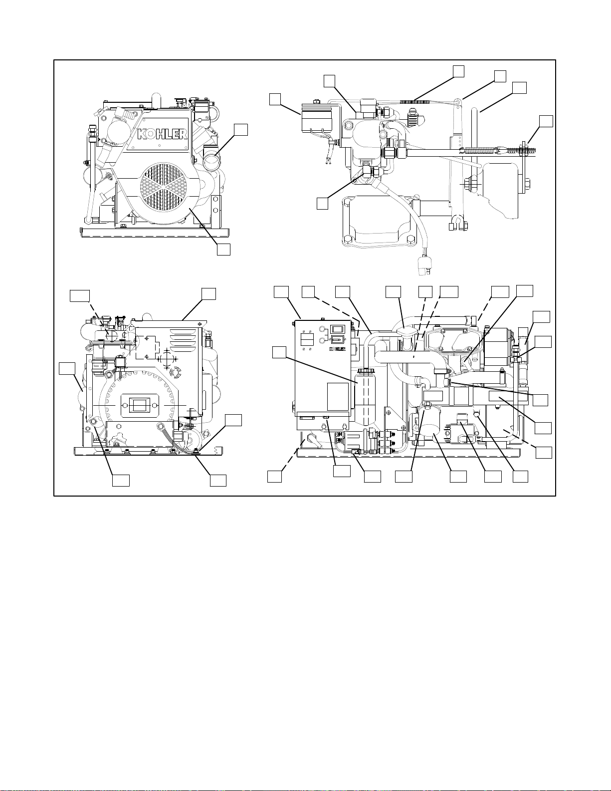
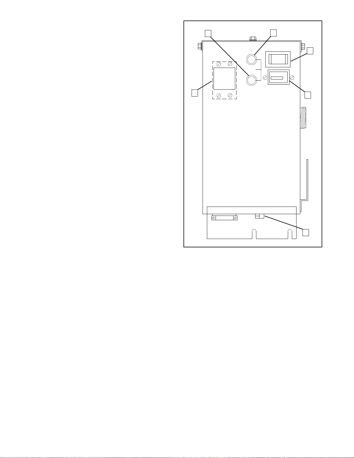
Service Views
36
32
4
5
6
7
3
8
1
9
2
10
30
INPUT
FUSE
CHRG.
STOP START
10A
1/10
00 0E00
TOTALHOURS
BATT.
17
16131211 143115
18
19
33
35
34
Figure 1-1. Service Views (typical)
1. Mixer Elbow (Exhaust Water Outlet)
2. Belt Guard
3. Electric Choke Rotary Solenoid
4. Carburetor
5. Governor Linkage
6. Governor Arm
7. Lifting Eye
8. Speed Adjustment (Idle Speed)
9. Antidieseling Solenoid
10. Controller
11. Battery Charger Voltage Regulator
12. Coolant Overflow Hose
13. Cooling System Pressure Cap
14. High Water Temperature Safety Shutdown
Switch
15. Thermostat
16. High Exhaust Temperature Shutdown
Switches (2)
17. Spark Plugs
18. Seawater Pump
29
28
27 26 25 24 23
258000-D
19. Oil Drain
20. Water Temperature Sender (Optional)
21. Heat Exchanger
22. Ignition Coil/Module
23. Low Oil Pressure Shutdown Switch/Sender
(Sender Optional)
24. Oil Dipstick (Oil Check/Oil Fill)
25. Oil Filter
26. Anticorrosion Zinc
27. Electric Fuel Pump
28. Remote Panel Connector
29. Positive Battery Lead Connection
30. Coolant Recovery Tank
31. Air Filter
32. Nameplate
33. Negative Battery Lead Connection
34. Equipment Ground Lug
35. Starter Solenoid
36. Starter Motor
20
21
22
TP-5695 12/931-6 Specifications
Page 22

Section 2. Operation
Prestart Checks
Toinsure continued satisfactory operation, the following
items should be checked before each start-up.
BACKFIRE FLAME ARRESTOR: Air cleaner must be
cleanand properlyinstalledto preventunfiltered airfrom
entering engine. See Maintenance--Air Cleaner.
BATTERY: Remove caps and check the electrolyte
level of each cell (batteries with filler caps only); add
distilled water if necessary. Check to make sure it is
connected correctly. Battery installation and
connections must meet Coast Guard Standards.
Battery should be serviced by authorized personnel
only. See Maintenance--Battery.
COMPARTMENT: Keep the engine room or
compartment clean and dry. Check for fuel or oil leaks.
Check the condition of fuel system, exhaust piping,
hoses, and muffler; have any faulty components
repaired before getting underway. Open hatch to air out
compartment and use “ignition-protected” bilge
blowers, if required, to clear fumes from area before
each start-up. If fuel leaks, fumes, exhaust gases, or
electrical sparks are noted, arrange for qualified
personnel to make necessary repairs before operating
generator set.
FUEL LEVEL: Make sure the fuel tanks are full and the
fuel system primed for operation. See
Maintenance--Fuel System.
OIL LEVEL: Should be ator nearMax. mark. Add oil as
neededtobringlevelupto this range. See Maintenance
Lubrication System.
COOLING: The coolant level on closed-type heat
exchanger systems can be checked using the coolant
recoverytank, if used. The MIN markindicatesfullwhen
coldandtheMAXmarkindicatesfullwhen hot. Maintain
the coolant level between these marks. It is
recommended that coolant level on closed systems be
periodically checked by removing pressure cap. Do not
solely rely on level in coolant recovery tank.
Add fresh coolant until level is just below overflow tube
opening. See Maintenance--Cooling Systems.
SEAWATER PUMP PRIMING: The seawater pump
must be primed before initial start-up. To prime pump,
close seacock and remove the hose from water filter
outlet. Fill hose and pump with clean water. Replace
hose and open seacock. Check for pump operating on
start-up by observing water discharge from exhaust
outlet.
TP-5695 12/93 Operation 2-1
Page 23
Controller
For identification and location of controller operating
features, refer to the text below and Figure 2-1.
1. Battery Charging Fuse protects battery charging
circuitry from short circuits.
2. Input (Controller) Fuse protects controller
circuitry from short circuits.
3. Start/Stop Switch is used to stop and start
generator set. Rock to start or stop position and
hold to start or stop engine. Switch automatically
returns to neutral center position when released.
4. Hourmeter records total generator set operating
hours. Use as a reference to schedule
maintenance.
5. Remote Start Connector provides connection
point for optional remote start kits.
6. Optional AC Circuit Breaker(s) protects
generator set from short circuits in load. Also used
to disconnect generator set from loads during
maintenance. To close circuit breaker,place in ON
position.
1
2
3
6
4
1. Battery Charging Fuse
2. Input (Controller) Fuse
3. Start/Stop Switch
Figure 2-1. Controller
5
A-246486-D
4. Hourmeter
5. Remote Start Connector
6. Optional AC Circuit
Breaker(s)
TP-5695 12/932-2 Operation
Page 24
Starting
WARNING
Explosion.
Gasoline vapors can cause explosion and
severe injury or death.
Iftheenginefailstostart after the first attempt, close the
seacock before a second start-up attempt. This action
will help prevent seawater from entering the engine
cylinders through the exhaust valve. Once the engine
starts,the seacock must be re-opened to allow passage
of cooling water.
NOTE
Failure to open the seacock after the generator set is
running will result in serious engine damage due to
overheating.
Before starting generator set, operate blower 4
minutes and check engine compartment for
gasoline vapors.
NOTE
For reliable starting, allow at least 30 seconds after
shutdown before restarting a hot engine.
Ensurethat the manual fuelshutoffvalve (if equipped)is
open. Then rock the master Start/Stop Switch on
controller (or use Start/Stop Switch on remote panel) to
theStartpositionfor amaximum of7 secondsoruntil the
engine starts.
NOTE
Do not crank the engine continuously for more than 7
seconds at a time. Allow a 5-second period between
starting attempts if the engine does not start. If the
engine fails to start after three attempts, contact an
authorized Kohler dealer/distributor for repair.Failure to
follow these guidelines may result in burn-out of the
starter motor from overheating.
NOTE
Ensure that the marine ship-to-shore transfer switch, if
used, is in proper position.
Stopping
Disconnectthe loadfrom thegenerator setandallow the
generator set to run at no-load for 5 minutes to cool
down the engine. Then rock the master Start/Stop
switch on the controller (or the Start/Stop Switch on a
remotepanel)totheStoppositionandhold it in the Stop
position until the generator set comes to a complete
stop.
NOTE
Allow unit to cometo a complete stop beforeattempting
to start the generator set again.
TP-5695 12/93 Operation 2-3
Page 25
Circuit Protection
AC Circuit Breaker (Optional)
before working on any equipment connected to
generator. The generator set can be started by remote
start/stop switch unless this precaution is followed.
The optional AC circuit breaker(s) located on the front
panel of the controller protect the generator output
windings.Ifaloadcircuit loses power,the cause may be
atrippedAC circuit breaker.If a tripped circuit breaker is
reset and then trips again, find and correct the short in
the load circuit that is causing the problem.
Input (Controller) Fuse (10 Amp)
The input fuse protects the controller circuitry. If the
generator set engine will not crank and the battery and
battery connections appear okay, the input fuse may be
blown. If this fuse, located on the front panel of the
controller, is replaced and then blows again, find and
correct the short that is causing the problem.
Battery-Charging Fuse (10 Amp)
The battery-charging fuse protects the battery-charging
circuit. If the battery goes dead and the battery and
battery-charging alternator are otherwise normal, the
battery-chargingfusemaybeblown. If this fuse, located
onthe front panelof the controller,isreplacedand blows
again, find and correct the short in the charging circuit
that is causing the problem.
NOTE
When a fuse replacement is required, be sure fuse has
the same ampere rating and is the same type (for
example: ABC or 3AB, ceramic). Do not substitute
“clear” glass-type fuses for ceramic fuses. If ampere
rating is unknown orquestionable, see Wiring Diagram.
Engine Safety
Shutdown Switches
The engine is protected by three engine safety
shutdown switches. Activating any of these switches
while the generator set is running, results in an
immediate, automatic shutdown. During start-up, the
engine safety shutdown feature is inhibited until a
generatoroutputissensedinordertoallowthe oil pump
output to reach normal operating pressure.
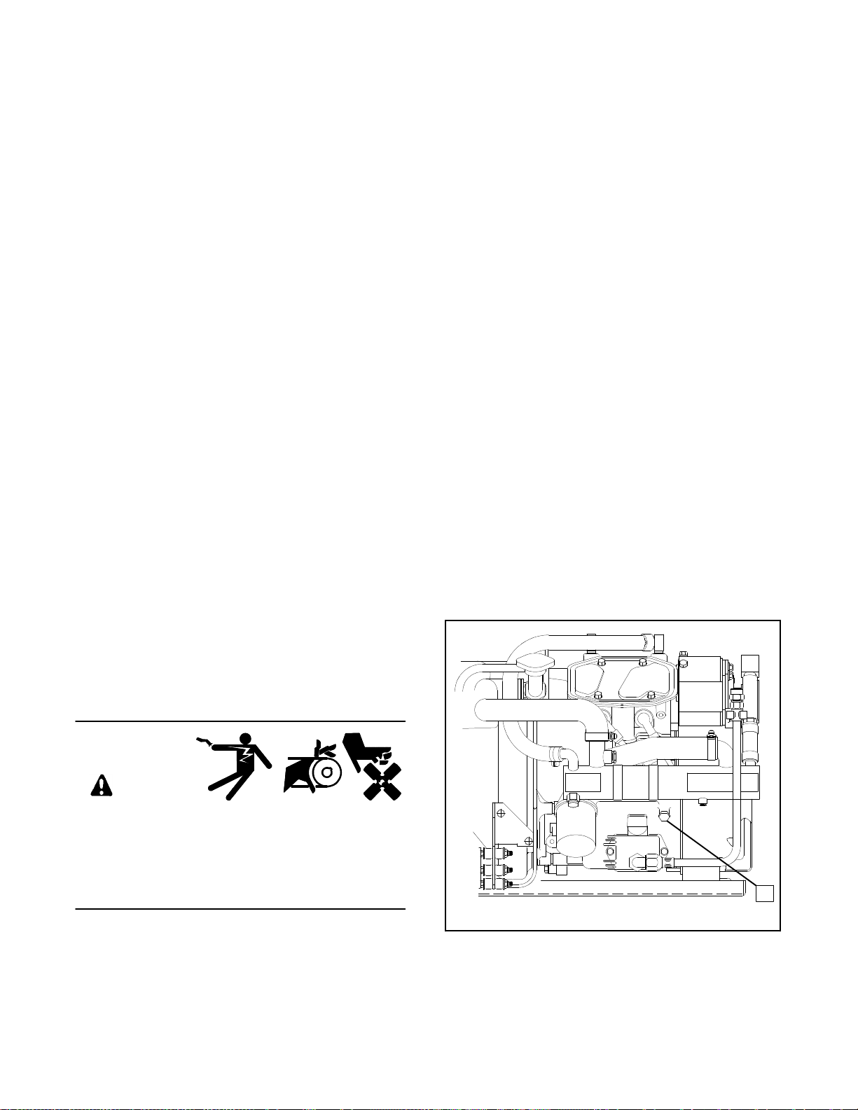
Low Oil Pressure Shutdown Switch
The low oil pressure shutdown switch protects the
engineagainst internaldamage,if the oilpressuredrops
below20 psi(138kPa), duetoan engineoilpump failure
or other engine malfunction. The location of the low oil
pressure shutdown switch is shown in Figure 2-2.
NOTE
The low oil pressure shutdown switch does not act as a
low oil level switch. The only way to protect against
engine damage due to low oil level is to check the oil
level regularly.
WARNING
Accidental starting.
Can cause severe injury or death.
Disconnect battery cables before working on
generator set (negative lead first and reconnect it
last).
Accidental starting can cause severe injury or
death. Disconnect battery cables (remove negative
lead first and reconnect it last) to disable generator set
1
258000-D
1. Low Oil Pressure Shutdown Switch
Figure 2-2. Low Oil Pressure Shutdown Switch
TP-5695 12/932-4 Operation
Page 26

High Water Temperature
High Exhaust Temperature
Shutdown Switch
The high water temperature shutdown switch protects
the engine against internal damage if the cooling water
temperature in the engine block is too high due to
cooling water or coolant circulation problems. The
switch is set to trip at 248--266° F (120--130° C). The
location of the high water temperature shutdown switch
is shown in Figure 2-3.
1 (hidden)
STARTSTOP
INPUT
10A
FUSE
1/10
00 000
TOTALHOURS
BATT.
CHRG.
258000-D
1. High Water TemperatureShutdown Switch
Figure 2-3. High Water Temperature
Shutdown Switch
Shutdown Switches
The two high exhaust temperature shutdown switches
protect the engine against internal damage due to
excessive exhaust temperatures. The switches are set
at 210--220° F (99--105° C). The locations of the high
exhaust temperature shutdown switches are shown in
Figure 2-4.
1
STARTSTOP
INPUT
10A
FUSE
1/10
00 000
TOTALHOURS
BATT.
CHRG.
258000-D
1. High Exhaust Temperature Shutdown Switches
(one located on each manifold)
Figure 2-4. High Exhaust Temperature
Shutdown Switches
TP-5695 12/93 Operation 2-5
Page 27

Remote Panels (Optional)
Remote Start Panel
Remote start panel allows starting-stopping from a
locationremoteofthegeneratorset.Generator sets are
equippedwitha6-pinconnectoroncontrollerbottomfor
connection of the kit. See Figure 2-5.
KOHLER
GENERATOR
1
2
START
1
STOP
1. “ON” Light 2. Start/Stop Switch
Figure 2-5. Remote Panel Features
2
1-656
Remote Start and
Two-Meter Panel Kit
Allows starting-stopping from a location remote of the
generator set. The illuminated gauges include an
engine oil pressure gauge and a water temperature
gauge. Generator sets come equipped with a 6-pin
connector on controller bottom for connection of the kit.
See Figure 2-6 for remote start and meter panel kit.
4 3
1-762
1. Engine Oil Pressure
2. Water Temperature
Figure 2-6. Remote Start and Two-Meter
Panel Features
Start/Stop Switch is a rocker-type switch with “ON”
light used to start and stop generator set.
Engine Oil Pressure Gauge measures engine oil
pressure. Normal engine operating range is 30--50 psi
(207--345 kPa).
NOTE
During the engine break-in period, it is normal for the
engine to produce higher oil pressure readings.
Water Temperature Gauge measures engine coolant
temperature. Normal engine operating range is
170--195_ F (77--91_ C).
3. Start/Stop Switch
4. “On” Light
TP-5695 12/932-6 Operation
Page 28

Remote Start and Four-Meter
Panel Kit
Allows starting-stopping from a location remote of the
generator set. The illuminated gauges include a DC
voltmeter, engine oil pressure gauge, water
temperature gauge, and generator running time
hourmeter.Generator sets come equipped with a 6-pin
connector on controller bottom for connection of the kit.
See Figure 2-7 for remote start and four-meter panel
features.
DC Voltmeter measuresvoltage of starting battery(ies).
Normalbattery operating range is 12--14 volts.
Engine Oil Pressure Gauge measures engine oil
pressure. Normal engine operating range is 30--50 psi
(207--345 kPa).
NOTE
During the engine break-in period, it is normal for the
engine to produce higher oil pressure readings.
Water Temperature Gauge measures engine coolant
temperature. Normal engine operating range is
170--195_ F (77--91_ C).
Start/Stop Switch is a rocker-type switch with “ON”
light used to start and stop the generator set.
1
6
5
Hourmeter records total generator set operating hours
for reference in maintenance scheduling.
2
3
4
1-830
1. Engine Oil Pressure
2. Hourmeter
3. Voltmeter
4. Water Temperature
5. Start/Stop Switch
6. “ON” Light
Figure 2-7. Remote Start and Four-Meter Features
TP-5695 12/93 Operation 2-7
Page 29

Section 3. Scheduled Maintenance
Use the following service schedule and the hourmeter
on the controller to schedule routine maintenance. In
addition to the routine services listed in this manual,
there are other important steps that should be taken to
keep a generator set in top condition. Usually tools and
instruments required for these additional steps are not
availableto thegeneratorset owner.Forthis reason,the
set should be returned periodically to an authorized
service dealer/distributor for complete servicing and
tune-up. The benefits of such service will be improved
performance and continuous satisfactory operation
duringa long trouble-free servicelife.Use the Operating
HourService Loginthe backofthis manualto document
services performed.
Service intervals are located on the top rows of the
Service Schedule chart. It indicates how often
maintenance tasks need to be done. Each service item
is to be repeated at the specified interval. For example,
an item required at 50 hours will again need to be
performed at 100 hours, 150 hours, etc.
Forcontinued satisfactoryoperation andlongevity ofthe
engine and generator set, proper maintenance and
eventual overhaul by a competent mechanic/technician
are essential. While it is not possible to anticipate
component failure, rough operation, metallic noises,
and excessive oil loss are among the indicators of
potential problems. Do not ignore these conditions!
NOTE
Operate the generator set with load applied at least
oncea month. Allow generator settorun about onehour
to reach operating temperature. This prevents the
formation of corrosion on internal engine components
when exposed to the breakdown of exhaust gases and
seawaterfor long periods ofgenerator inactivity.If unitis
to be out of service for several months, see Storage
Procedure.
WARNING
Accidental starting.
Can cause severe injury or death.
Disconnect battery cables before working on
generator set (negative lead first and reconnect it
last).
Accidental starting can cause severe injury or
death. Disconnect battery cables (remove negative
lead first and reconnect it last) to disable generator set
before working on any equipment connected to
generator. The generator set can be started by remote
start/stop switch unless this precaution is followed.
NOTE
HARDWARE DAMAGE! Engine and generator make
useof bothAmerican Standardandmetric hardware.Be
sure to use the correct size tools to prevent rounding of
bolt heads and nuts.
NOTE
High-mineral content seawater (salt water) can cause
rapid destruction of metals. Wipe up all salt water
spillage on and around generator set and keep metal
surfaces free from accumulated salt deposits.
TP-5695 12/93 Scheduled Maintenance 3-1
Page 30

Service Schedule
After 20
Hrs. or
Before
Starting
LUBRICATION SYSTEM
Check oil level X
Change oil
Change oil filter X
FUEL SYSTEM
Check the fuel level X
Fill fuel tank X
Lubricate carburetor and choke
linkage
Clean fuel screen X
Service fuel lines X
IGNITION SYSTEM
Replace spark plugs X
COOLING SYSTEM
Check coolant level X
Check seawater outlet
Inspect exhaust system
components for cracks and
corrosion (exhaust manifold,
mixing elbow, exhaust line,
hose clamps, silencer, and
outlet flapper)
Check function of siphon break
(if equipped)
Check condition of heat
exchanger anticorrosion zinc
Replace heat exchanger
anticorrosion zinc
Replace the impeller of
seawater pump
Check thermostat function X
INTAKE/EXHAUST SYSTEM
Check exhaust gas condition
Clean the exhaust/water mixing
elbow
Clean air filter element X
X (During
Operation)
X X
X (During
Operation)
One
Month
X (Break-in
Period)
X (Break-in
Period)
Every 50
Hrs. or 3
Months
X
Every
100 Hrs.
or 6
Months
X (100 Hrs.
or 3
Months)
X
Every
200 Hrs.
or Yearly
X
X
X
Every
300 Hrs.
or 2 Years
X
TP-5695 12/933-2 Scheduled Maintenance
Page 31

Service Schedule (Continued)
After 20
Hrs. or
Before
Starting
ELECTRICAL SYSTEM
Check electrolyte level
(Batteries with filler caps only)
Check and tighten electrical
connections
Check specific gravity
(Batteries with filler caps only)
Clean battery cables X
ENGINE AND MOUNTING
Check for leakage of water, fuel,
or oil
Lubricate governor linkage
Retighten all major nuts and
bolts
Check and tighten mounting
bolts and vibromounts
Check intake/exhaust
valve clearance
REMOTE CONTROL SYSTEM,
ETC.
Check compartment condition
(fuel, oil, or water leaks)
Check the remote control
operation
Test run generator set
GENERATOR
Blow dust out of generator X
X X
X X
X
One
Month
X (Break-in
Period)
X (Break-in
Period)
X (Break-in
Period)
X
(Monthly)
Every 50
Hrs. or 3
Months
Every
100 Hrs.
or 6
Months
X
X
Every
200 Hrs.
or Yearly
X
X
X
Every
300 Hrs.
or 2 Years
X
TP-5695 12/93 Scheduled Maintenance 3-3
Page 32

Lubrication System
Specifications
Use high quality detergent oil of API (American
PetroleumInstitute) service class SF,SF/CC, or SF/CD.
This information can be found on most oil containers,
see Figure 3-1. The symbol illustratedidentifies theAPI
service class in the upper portion. The center indicates
the SAE (Society of Automotive Engineers) viscosity
grade. The bottom portion (when used) signifies the oil
is intended to improve fuel economy and displays the
phrase “Energy Conserving.” Select viscosity based on
the air temperature at the time of operation. (See
Figure 3-2.)
SAE 10W40 is the preferred oil for general use where
temperatures permit.
Oil Check
Checkoillevelincrankcasedaily or before each startup
to insure that the level is in the safe range.
NOTE
Do not check oil level when unit is running. Generator
set must be stopped and level to get an accurate
reading.
If generator set has just been run, allow a few minutes
for the oil to return to the oil pan before checking level.
To check oil level, remove dipstick and wipe the end
clean, place bottom thread of dipstickagainst oil fill hole
and remove. Do not screw in dipstickwhen checking oil
level. Level should bebetween MIN and MAX marks on
dipstick. See Figure 3-3.
NOTE
Do not operate the set if thelevel isbelow the MIN mark
or above the MAX mark. Oil above the MAX mark is
wasted due to increased oil consumption.
1--792
Figure 3-1. Oil Service Class and
SAE Viscosity Grade Symbol
When Outside Temperature
is Consistently:
Below 5_ F (--15_ C)
--5_ F (--21_ C) to
90_ F (32_ C)
Above 15_ F (--10_ C)
Above --5_ F (--21_ C)
Figure 3-2. Recommended SAE
Viscosity Grades
Using other than the appropriate service class oil or
extended oil change intervals could cause engine
damage which is not covered by the engine warranty.
Do not mix oils of different viscosities. It is also best not
to mix different brands of oils. Possible incompatibility
could cause a breakdown of lubricating ingredients and
reduce engine protection.
Use SAE
Viscosity Grade:
5W30
10W30
20W40 or 20W50
10W40 (Preferred)
1. MAX Limit
2. MIN Limit
Figure 3-3. Checking Oil Level
1
3. Safe Range
2
3
1-826
TP-5695 12/933-4 Scheduled Maintenance
Page 33

Adding Oil
It is normal to add some oil between oil changes. The
amountwill vary with the usage.Openfill cap and pour a
small amount of oil using a funnel or other suitable
pouring device. See Figure 3-4. Wait a few minutesand
check level. If necessary, add more oil and then check
again. Each time be sure to add small quantities and
check to prevent overfilling.
1. Place oil drain hose in a proper container. Remove
oil drain cap. If a drain pump is used, remove oil
draincap and connect oil drainhoseto drain pump.
2. Allow ample time for all oil to drain into container. If
drain pump is used, activate pump until oil is
removed.
3. Loosen oil filter by turning in a counterclockwise
direction. Oil filter is 2 1/2 in. (64 mm) dia. with 14
flutes. Use oil filter wrench, if necessary. See
Figure 3-6. Use rags to handle hot oil filter and
clean up spilled oil. Remove filter from oil filter
adapter on engine and discard oil filter in a proper
container.
4. Clean contact surface of oil filter adapter.
5. Lightly lubricate the gasket surface of new oil filter
with fresh engine oil. Thread oil filter onto oil filter
adapter until gasket makes contact; then
hand-tighten oil filter an additional 3/4 turn.
1-826
Figure 3-4. Adding Oil
Oil Change/Oil Filter Change
Change oil and oil filter every 200 hours or yearly.
Change oil more frequently under dirty, dusty
conditions.Changeoilwhile theengine isstill warm.See
Figure 3-5 and use the following procedure.
1
STARTSTOP
INPUT
10A
FUSE
1/10
00 000
TOTALHOURS
BATT.
CHRG.
258000-D
1. Oil Drain Cap
Figure 3-5. Oil Drain Cap
NOTE
If an automatic oil drain/oil fill pump is used, omit
Step 6. Fill with proper amount and type of oil, see
Step 6. When complete, replace cap and
disconnect pump.
6. Replace oil drain cap. Remove oil fill cap. Add oil
usinga funnelorother suitablepouring device.See
Specifications—Engine for oil capacity and
Lubrication System—Specifications for proper
service class and SAE viscosity of oil. Replace oil
fill cap.
7. Start generator set and check for leaks at oil drain
cap and oil filter.
8. Stop generator set. Wait a few minutes for oil to
return to oil pan. Remove dipstick and wipe clean,
reinsert as far as possible and remove to check oil
level. Add oil, as necessary, to bring level up to
MAX mark.
TP-5695 12/93 Scheduled Maintenance 3-5
Page 34

1
1. Oil Filter Wrench 2 1/2 in. (64 mm) Dia.
Figure 3-6. Removing Oil Filter
1-826
Fuel System
Specifications
For best results, use only clean fresh, regular grade
unleaded gasoline. Use fuel with a minimum octane
rating as designated by the following:
Antiknock Index (Average of Research 86
Octane Number and Motor Octane Number)
Unleaded fuel is recommended since it leaves less
combustion chamber deposits. Oil must not be mixed
with fuel.
If using a gasoline containing alcohol (gasohol), be sure
the octane rating is at least 86(Antiknock Index). There
are two types of gasohol: one containing ethanol, and
another containing methanol.
Do not use gasohol that contains more than 10%
ethanol. Do not use gasohol containing methanol
(methyl or wood alcohol) that does not also contain
cosolvents and corrosion inhibitorsfor methanol. Never
usegasoline containing more than 5%methanol,even if
it has cosolvents and corrosion inhibitors.
NOTE
Fuel system damage and engine performance
problems resulting from the use of such fuels are not
coveredunderWarranty.Hondacannot endorsethe use
offuels containingmethanolsince evidenceofsuitability
is as yet incomplete. Before purchasing fuel from an
unfamiliar station, try to confirm whether the fuel
contains alcohol, and to what percentage. If any
undesirableoperating symptoms are noticed after using
a gasoline that contains alcohol, or one that contains
alcohol, switch to a gasoline that does not contain
alcohol.
NOTE
Discontinue use of any gasohol or alcohol/gasoline
blend if engine performance or fuel system problems
occur. Do not use such fuel unless it is UNLEADED.
Usefresh gasoline to ensure itisblended for the season
and to prevent the formation of gum deposits which
could clog the fuel system. Do notuse gasolineleft over
from the previous season.
TP-5695 12/933-6 Scheduled Maintenance
Page 35

Fuel Pump Screen
3. Remove the three nuts that secure the electric fuel
pump to the mounting bracket.
4. Remove the three mountingstuds from theelectric
fuel pump.
WARNING
Explosive fuel vapors.
Can cause severe injury or death.
Useextreme care when handling, storing,
and using fuels.
Explosive fuel vapors can cause severe injury or
death.Allfuelsarehighlyexplosiveinavapor state.Use
extreme care when handling, storing, and using fuels.
Store fuel in a well-ventilated area away from
spark-producing equipment and out of the reach of
children. Never add fuel to the tank while the engine is
running since spilled fuel may ignite on contact with hot
parts or from ignition spark. Do not smoke or permit
flame or spark to occur near potentialsources of spilled
fuelorfuelvapors.Keepfuellinesand connections tight
and in good condition—don’t replace flexible fuel lines
with rigid lines. Flexible sections are used to avoid
breakage due to vibration. Should any fuel leakage, fuel
accumulation, or electrical sparks be noted, DO NOT
OPERATE GENERATOR SET.Have systems repaired
before resuming generator operation.
5. Remove the cover plate and inspect the screen.
Remove any debris orresidue. Be sure the screen
is intact. If the screen is damaged, replace the fuel
pump.
6. Check the O-ring seal. Replace the O-ring if it is
nicked or eroded.
7. Reinstall the cover plate and secure it to the fuel
pump by reinstalling the three mounting studs.
8. Insert the three mounting studs on the fuel pump
through the mating holes in the mounting bracket.
Reinstall the three nuts to secure the fuel pump in
place.
9. Reconnect the fuel lines to the fuel pump.
10. Open fuel line at tank or in-line shutoff valve and
check for leaks from the fuel pump at fuel line
connections and cover plate.
Gasoline—Store gasoline only in approved red
containers clearly marked GASOLINE. Do not store
gasoline in any occupied building.
The electric fuel pump includes a screen. (See
Figure 3-7.) At the recommended interval or when
clogging is suspected, inspect and clean the screen as
follows:
1. Shut off fuel flow to electric fuel pump at tank or at
in-line shutoff valve. Disconnect harness plug(see
Figure 3-7 for location).
2. Disconnect fuel lines from electric fuel pump,
drainingfuel fromthelines andpumpinto asuitable
container to prevent spillage into the bilge.
1
2 (enclosed)
258000-D
1. Harness Plug 2. Fuel Pump Screen
Figure 3-7. Fuel Pump Screen
TP-5695 12/93 Scheduled Maintenance 3-7
Page 36

Carburetor/Choke Lubrication
Theonly maintenancerequiredis to lubricatecarburetor
and choke linkage at the specified interval using white
lithium grease or lubriplate.
WARNING
Carburetor Adjustments
The carburetor is a single-barrel, horizontal design and
uses an electric choke.
Lack of power usually indicates that the fuel mixture is
too rich. An overrich mixture may also be caused by a
clogged air intake (backfire flame arrestor)—check this
before readjusting carburetor. Fuel mixture may be too
lean if engine skips or backfires. Minor carburetor
adjustment may be necessary to compensate for
differences in altitude, fuel, and temperature.
1. With ENGINE STOPPED, turn fuel mixture screw
in (clockwise) until it seats lightly. DO NOT
FORCE! Turn fuel mixture screw out 2 to
2 1/2 turns. See Figure 3-8.
2. Start engine and let it run at no load for about 5
minutes. Before making adjustments engine
should be thoroughly warmed up running at
governed speed, and connected to full load.
Fire.
Can cause severe injury or death.
Do not smoke or permit flame or spark to occur
near fuel or fuel system.
Asudden flashfire cancause severeinjury ordeath.
Donot smokeorpermit flameorspark tooccur nearfuel
system.Keepthecompartmentandgeneratorsetclean
and free of debris to minimize chances of fire. Wipe up
all spilled fuel and engine oil.
2
1
3. Turn low speed mixture screw in until engine
instability (hunting) develops and then screw out
until engine instability is again apparent. Turn
screwbackin until it is positioned halfway between
the points of increasing stability. When properly
adjusted, engine will operate with steady governor
action.
4. Toadjustthe idle speed, runthegenerator set atno
load. Push the throttle lever counterclockwise until
it hits the idle speed screw. Holding the throttle
leveragainstthescrew,adjustthe idlespeedscrew
untilunit runs at55Hz (3300 rpm)for60 Hz models
or 45 Hz (2700 rpm) for 50 Hz models.
NOTE
If engine runs poorly after adjusting carburetor and
doing scheduled maintenance, return generator
set to an authorized service dealer/distributor to
have problem corrected.
1. Governor Arm
2. Low Speed
Mixture Screw
Figure 3-8. Fuel Mixture Adjustment
3. Idle Speed Screw
1-829
3
1-829
TP-5695 12/933-8 Scheduled Maintenance
Page 37

Ignition System
Ignition System Service
The ignition system is transistorized and breakerless.
Under normal conditions, only the spark plugs need
service on a regular basis. The electronic ignition
module requires no maintenance and should giveyears
of trouble-free service. If a module problem is
suspected, have service performed by an authorized
service dealer/distributor.
Spark Plugs
At the recommended interval (shown in the service
schedule) service spark plugs.
1. Remove spark plug wires by grasping boot and
turning slightly while pulling. Do not pull wire. See
Figure 3-9.
NOTE
Pullingwireratherthanbootmaycausedamageto
wire or terminal.
NOTE
Do not sandblast, wire brush, scrape, or otherwise
service spark plug in poor condition. Best results
are obtained with a new plug.
1-827
Figure 3-9. Removing Spark Plug Wires
2. Where possible, usecompressed air to removedirt
from around each spark plug before removal. This
procedurewillpreventdirtparticlesfrom falling into
combustion chamber. Loosen spark plug with a
ratchetandsparkplugsocket witharubberinsertto
prevent damage to spark plug. See Figure 3-10.
Remove spark plugs one at a time and examine.
See Figure 3-11 to evaluate engine conditions by
color/condition of spark plugs.
3. Clean spark plugsbywiping with a rag and then file
the center electrode so that it is parallel to the side
electrode. Should replacement be necessary, see
“Specifications” for spark plug type.
1
1-827
1. 13/16 in. Spark Plug Socket
Figure 3-10. Removing Spark Plug
TP-5695 12/93 Scheduled Maintenance 3-9
Page 38

Problem Means of Identification Possible Cause
Normal Light tan or gray deposit on the
firing tip.
Gap bridged Deposits built-up and closing gap
between electrodes.
Oil fouled Wet black deposits on the insulator
shell bore electrode.
Carbon fouled Black, dry fluffy carbon deposits
on insulator tips, exposed shell
surfaces, and electrodes.
Lead fouled Dark gray, black, yellow, or tan
deposits; or a glazed coating on
the insulator tip.
Pre-ignition Melted electrodes and possibly
blistered insulator. Metallic deposits
on insulator suggests internal
engine damage.
Overheating White or light gray insulator with
small black or gray/brown spots
with bluish (burnt) appearance on
electrodes.
Worn Severely eroded or worn
electrodes.
Good operating conditions and
maintenance.
Oil or carbon fouling. Clean and
regap.
Excessive oil entering combustion
chamber through worn rings and
pistons, excessive clearance
between valve guides and stems,
or worn or loose bearings.
Replace plug.
Using too cold range plug, weak
ignition, clogged air intake or
improper carburetor adjustments,
defective fuel pump, overrich fuel
mixture, or excessive no load
operation. Clean and regap.
Caused by highly leaded fuel.
Replace plug.
Wrong type of fuel, incorrect timing
or advance, too hot of a plug, burnt
valves, or engine overheating.
Replace and plug.
Engine overheating, wrong type of
fuel, loose spark plugs, too hot a
plug, low fuel pump pressure or
incorrect ignition timing. Replace
plug.
Caused by normal wear and failure
to replace at proper interval.
Replace plug.
Figure 3-11. Spark Plug Condition
4. Before installing any spark plug, check the gap.
See Figure 3-12. The proper gap is attained when
the feeler (or wire) gauge just passes between the
spark plug electrodes. It should pass easily, but
with some resistance or drag. The correct gap is
0.028--0.031 in. (0.7--0.8 mm).
5. To readjust the spark plug gap, use gapping tool to
gently bend the side electrode closer to or further
from the center electrode. See Figure 3-13. The
side electrode must be centered over the center
electrode.
6. Being careful not to bump the electrode, hand
threadspark plug clockwise into cylinder head until
resistance is felt.
7. Using atorque wrench, tighteneach sparkplugto a
torque of 18--22 ft. lbs. (20--30 Nm). If a torque
wrench is not available, hand-tighten spark plug
until resistance is felt and then use a ratchet
wrench to tighten the plug an additional 1/2 turn (if
installing a new plug) or 1/8--1/4 turn (if reinstalling
a used plug). Do NOT overtighten asthis may strip
threads or alter electrode gap setting.
8. Check spark plug wire connector in boot for
accumulated dirt, grease, etc., and clean as
necessary. Firmly push spark plug connector and
boot onto spark plug.
TP-5695 12/933-10 Scheduled Maintenance
Page 39

1
2
1. 0.028--0.031 in.
(0.7--0.8 mm) Gap
2. Spark Plug Electrodes
Figure 3-12. Checking Spark Plug Gap
1-514
1-511
Figure 3-13. Adjusting Spark Plug Gap
TP-5695 12/93 Scheduled Maintenance 3-11
Page 40

Cooling Systems—
Closed/Heat Exchanger
In a closed cooling system, the seawater does not
circulate through the engine but circulates through
separate chambers within the heat exchanger to cool
the engine coolant. The seawater is then mixed with
engine exhaust and ejected out the exhaust outlet. The
coolant is circulated through cooling passages to cool
theengine. All models make useofa coolant thermostat
andacoolantrecoverytank.The coolant capacity of the
engine with heat exchanger is 0.72 U.S.qts. (0.68L) for
all models. A solution of 50% ethylene glycol and 50%
clean, softened water is recommended to inhibit
rust/corrosion.A coolantsolutionof 50% ethyleneglycol
will provide freezing protection to --34°F (--37°C) and
overheating protection to 265°F (129°C). A coolant
solution with less than 50% ethylene glycol may not
provide adequate freezing and overheating protection.
A coolant solution with more than 50% ethylene glycol
can cause damage to engine and components. Do not
use alcohol or methanol antifreeze or mix them withthe
coolant.
Filling and Checking
WARNING
Hot coolant and steam.
Can cause severe injury or death.
NOTE
ENGINE DAMAGE! Failure to bleed air from cooling
system may cause overheating and subsequent
damage to engine.
NOTE
Special attention should be given when checking for
propercoolant level. After the coolanthas been drained,
it normally requires some time before complete refill of
the engine water jacket takes place.
Before filling the cooling system, verify that all hose
clamps are tight. Loosenair-bleed screw located ontop
of the engine to allow trapped air to escape. See
Figure 3-14. Place a rag around the screw to prevent
coolant spillage onto the block. Remove pressure cap
locatedon thetopof theengine(see Figure 3-15)and fill
with the recommended coolant until level is just below
overflow tube opening. Tighten air-bleed screw when
coolant, free of air bubbles, starts to flow. Replace
pressure cap. Start generator set and allow to run for
about20--30seconds.STOP generatorsetand recheck
coolant level by removing pressure cap. Repeat
procedure, as necessary,until coolant can nolonger be
added.
A coolant overflow bottle is provided. Fill bottle to just
below the MAX mark. See Figure 3-16. Maintain proper
coolant level in coolant overflow bottle. The MIN mark
indicates full when coldand the MAX mark indicatesfull
when hot. Coolant level should always be between
these marks. The coolant level can be checked using
the overflow bottle markings, but it is recommended to
periodicallyremove the coolant pressure cap andcheck
coolant level.
Before removing pressure cap stop generator,
allow to cool and loosen pressure cap to relieve
pressure.
Hot coolant can cause severe injury or death. Allow
engine to cool and release pressure from cooling
system before opening pressure cap. To release
pressure, cover thepressure cap with a thick cloth then
turn it slowly counterclockwise to the first stop. After
pressure has been completely released and the engine
has cooled, remove cap. If generator set is equipped
witha coolantrecoverytank, checkcoolantlevel at tank.
TP-5695 12/933-12 Scheduled Maintenance
Page 41

1
1
STARTSTOP
INPUT
10A
FUSE
1/10
00 000
TOTALHOURS
BATT.
CHRG.
1. Air-Bleed Screw; Use 12 mm Wrench
Figure 3-14. Air-Bleed Screw
1
STARTSTOP
INPUT
10A
FUSE
1/10
00 000
TOTALHOURS
BATT.
CHRG.
1. Coolant Recovery Tank
2. Overflow Hose
3
2
3. Coolant Pressure Cap
Figure 3-15. Coolant Pressure Cap
1-828
258000-D
2
258000-D
1. MAX. Mark 2. MIN. Mark
Figure 3-16. Checking Coolant Level
TP-5695 12/93 ScheduledMaintenance 3-13
Page 42

Flushing and Cleaning
If required, flush coolant from generator set. To properly
flush coolant, obtain Kit #267999 and use the following
procedure:
WARNING
Accidental starting.
Can cause severe injury or death.
Disconnect battery cables before working on
generator set (negative lead first and reconnect it
last).
4. Connect a garden hose to the female connector of
large kit hose. Place the free end of the small kit
hose in a 1--2 gal. (min.) bucket.
NOTE
Heat exchanger pressure cap MUST be installed.
5. Turn on water supply to flush coolant from engine
block. Turn off water supply when clean water is
observed coming from hose in bucket.
6. Disconnect gardenhose.Place free endoflarge kit
hoseintobucketandconnectanairhose tothe free
end of the smaller kit hose. Apply air pressure (40
psi[276 kPa] min.) until waterstopsflowing from kit
hose in bucket. This will remove about 16 fl. oz.
(0.47 L) of water from engine block.
Accidental starting can cause severe injury or
death. Disconnect battery cables (remove negative
lead first and reconnect it last) to disable generator set
before working on any equipment connected to
generator. The generator set can be started by remote
start/stop switch unless this precaution is followed.
WARNING
Hot coolant and steam.
Can cause severe injury or death.
Before removing pressure cap stop generator,
allow to cool and loosen pressure cap to relieve
pressure.
Hot coolant can cause severe injury or death. Allow
engine to cool and release pressure from cooling
system before opening pressure cap. To release
pressure, cover thepressure cap with a thick cloth then
turn it slowly counterclockwise to the first stop. After
pressure has been completely released and the engine
has cooled, remove cap. If generator set is equipped
witha coolantrecoverytank, checkcoolantlevel at tank.
NOTE
Engine coolant capacity is 23 fl. oz. (0.68 L).
NOTE
Some small air compressors may not maintain
pressure under the required flow conditions. In
these cases, it isrecommended that the endof the
kit hose in the bucket be closed off momentarily
until pressure is allowed tobuild up. After pressure
has accumulated, open end to allow water to flow
into bucket. Repeat closing and opening end of kit
hose, as required.
7. Remove kit hoses with hose fittings from engine.
8. Apply pipe sealant to threads of high water
temperature safety shutdown switch and install
switch in thermostat housing. Reconnect wiring
harness lead to switch.
9. Apply pipesealant totheair-bleed screwand install
screw into engine. Do not final tighten!
10. Remove cap of coolant overflow bottle and pour
contents into a suitable container. Reinstall bottle
on unit.
11. Add fresh coolant to coolant overflow bottle. A
solution of 50% ethylene glycol and 50% clean,
softened water is recommended to inhibit rust/
corrosion and provide freezing protection. Fill to
MIN mark. Install coolant overflow bottle cap.
1. Disconnect the battery, negative lead first.
2. With engine cooled, remove the air-bleed screw
and the high water temperature safety shutdown
switch from the thermostat housing.
3. Connect kit hose fittings to the engine. Install kit
hoses to fittings (if not already done).
12. Remove heat exchanger pressure cap and add
about 5 fl. oz. (0.15 L) of clean, softened water.
Then fill remainder of engine with straight coolant
(100%) until level is just below the overflow tube
opening. Final tighten the air-bleed screw when
coolant,free of air bubbles, startstoflow.Install the
heat exchanger pressure cap.
TP-5695 12/933-14 Scheduled Maintenance
Page 43

13. Reconnect battery, negative lead last.
14. Start generator set and allow the set to run for
about 20--30 seconds. Stop generator set and
recheck coolant level byremoving heat exchanger
pressure cap. Add straight coolant, if necessary,
until level is just below the overflow tube opening,
then reinstall pressure cap. Repeat this step until
coolant can no longer be added. This procedure
should give an approximate mixture of 50%
ethylene glycol and 50% water.
15. Wipe up spilled coolant and water with rags.
Dispose of rags in a proper container.
16. Test run generator set for about five minutes and
check for coolant leaks. This will allow the coolant
mixture to mix completely. Stop generator set.
17. Rinse coolant flush kit hoses and fittings withclean
water. Store kit for future use.
18. Dispose of used coolant in a proper manner. Do
NOT pollute waterways!
TP-5695 12/93 ScheduledMaintenance 3-15
Page 44

Anticorrosion Zinc
An anticorrosion zinc anode is installed in the heat
exchangerto preventelectrolyticcorrosion byseawater.
When different metals, such as iron and copper, are
placed in a highly conductive liquid (seawater), the iron
gradually rusts. The zinc has chemical propertieswhich
cause the seawater to react to it rather than the engine
components.
The anticorrosion zinc anode should be checked every
100 hours or three months and replaced every 200
hours or yearly. Depending upon operating conditions
and seawater properties, the anticorrosion zinc anode
may have to be replaced more frequently. See
Figure 3-17 and use the following procedure.
STARTSTOP
INPUT
10A
FUSE
1/10
00 000
TOTALHOURS
BATT.
CHRG.
1. With generator set cooled, drain the cooling
seawater system. Close seacock, remove
anticorrosion zinc anode from heat exchanger.
2. Use a wire brush to remove the loose corrosion on
the anticorrosion zinc anode. Replace the anode
when less than 50% of the 11/32 in. (9 mm) dia. by
9/16 in. (14 mm) long portion of zinc remains.
3. Clean threaded hole of heat exchanger and coat
threads of anticorrosion zinc anode with pipe
sealant (suitable for marine applications). Install
anticorrosion zinc anode into heat exchanger.
4. Open seacock. Start generator set and check for
leaks at the anticorrosion zinc anode location.
Check for seawater flow by observing water
discharge from exhaust outlet.
2
1
258000-D
1. Heat Exchanger 2. Anticorrosion Zinc
Figure 3-17. Removing Anticorrosion Zinc
TP-5695 12/933-16 Scheduled Maintenance
Page 45

Pressure Cap
Closed-loop cooling systems incorporate a pressurized
capto raisethe boilingpoint ofthecoolant andmake use
of higher operating temperatures. If leakage or
malfunction occurs, replace the pressurized cap with
one supplied by Kohler Co. part number 229958.
1
2
3
valvedownward intothemounting base.Installretaining
cap and tighten finger-tight only. Do NOT overtighten.
Air Cleaner and
Mixing Elbow
Servicing Air Cleaner
The engine is equipped with a dry-type air cleaner.
Every 50 hours (more often if operating under dusty or
dirtyconditions) remove element andserviceby tapping
element lightly against flat surface to dislodge loose
surface dirt. Do not clean in any liquid or blow out with
compressedairasthiswillruin filter material in element.
Service air cleaner after each 50 hours of operation. If
dirty, bent, or damaged replace element with genuine
Kohler replacement. See Figure 3-19.
1-779
1. Mounting Base
2. Retaining Cap
Figure 3-18. Siphon Break
3. Reed Valve Assembly
Siphon Break
An optional siphon break is used to prevent seawater
entry into the engine when the generator set is shut
down.Corrosion buildup may not allowthe siphon break
tofunction properly.Therefore, if used, the siphonbreak
must be inspected and cleaned periodically.
NOTE
To prevent siphoning of seawater, run the generator
while performing this inspection.
Removethe retaining cap to inspect the reed valve. See
Figure 3-18. Clean the reed valve to remove residue
and oxidation. Check that the reed valve (opening) is
clear. Replace the siphon break if the material has
hardened or deteriorated. Install the reed valve with the
1-905
Figure 3-19. Air Cleaner Service
Servicing Mixing Elbow
The mixing elbow combines high temperature exhaust
and cooling seawater. These conditions are conducive
to rapid deterioration and, combined with engine
vibrations,premature failures if notproperlymaintained.
Check the mixing elbow for carbon buildup and
corrosion inside the pipe. Clean or replace the mixing
elbow as necessary. Inspect the exhaust manifold
mounting threads for cracking and corrosion.
TP-5695 12/93 ScheduledMaintenance 3-17
Page 46

Battery
The starting battery should be a 12-volt unit with a
minimum 250 CCA (cold cranking Amps) at 0_ F (--18_
C). When using a maintenance-free battery it is not
necessary to check the specific gravity or electrolyte
level. Otherwise, these procedures should be done at
the intervals specified in the Service Schedule.
Cleaning
Keep battery clean by wiping it with a damp cloth. Keep
all electrical connections dry and tight. If corrosion is
present, disconnect cables from battery and remove
corrosion with a wire brush. Clean battery and cables
with a solution of baking soda andwater.Be careful that
cleaning solution does not enter battery cells. When
cleaningis complete,flushbattery andcableswith clean
water and wipe with a dry cloth. After the battery cables
are reconnected, coat terminals with petroleum jelly,
silicon grease, or other nonconductive grease.
Checking Electrolyte Level
WARNING
Sulfuric acid in batteries.
Can cause severe injury or death.
Use protective goggles and clothes. Can cause
permanent damage to eyes, burn skin, and eat holes
in clothing.
Sulfuric acid in batteries can cause severe injury or
death. Sulfuric acid in battery can cause permanent
damage to eyes, burn skin, and eat holes in clothing.
Alwayswearsplash-proof safety goggles when working
around the battery. If battery electrolyte is splashed in
the eyes or on skin, immediately flush the affected area
for15 minutes with large quantities of clean water.In the
caseofeyecontact,seek immediate medical aid. Never
addacid toabattery oncethebattery hasbeenplaced in
service. Doing so may result in hazardous spattering of
electrolyte.
Explosion can cause severe injury ordeath. Battery
gases can cause an explosion. Do not smoke or permit
flame or spark to occur near a battery at any time,
particularly when it is being charged. Avoid contacting
terminalswith tools, etc. to prevent burns and toprevent
sparks that could cause an explosion. Remove
wristwatch,rings,andanyotherjewelry before handling
battery. Never connect negative (--) battery cable to
positive (+) connection terminal of starter solenoid. Do
not test battery condition by shorting terminals together
or sparks could ignite battery gases or fuel vapors. Any
compartment containing batteries must be well
ventilated to prevent accumulation of explosive gases.
To avoid sparks, do not disturb battery charger
connections while battery is being charged and always
turn charger off before disconnecting battery
connections. When disconnecting battery, remove
negative lead first and reconnect it last.
Check the level of electrolyte before each startup.
Remove filler caps and check to see that electrolyte
level is up to bottoms of filler holes, see Figure 3-20.
Refill as necessary with distilled water or clean tap
water.DO NOT add fresh electrolyte!Then reinstall and
tighten filler caps. If water is added during freezing
temperatures, run generator set 20--30 minutes to allow
mixing of added water and electrolyte. This will prevent
damage to battery due to freezing.
1
2
1-046
1. Filter Caps 2. Electrolyte Level
Figure 3-20. Checking Electrolyte Level
Checking Specific Gravity
Usea battery hydrometertocheck the specificgravityof
the electrolyte in each battery cell. Correct actual
hydrometer readings for temperature.If the hydrometer
used does not have a correction table, use the one in
Figure 3-21. The battery is fully charged if the specific
gravity is 1.260 at an electrolyte temperature of 80_ F
(26.7_ C). The difference between specific gravities of
TP-5695 12/933-18 Scheduled Maintenance
Page 47

each cell should not exceed ±0.01. The battery should
be charged if the specific gravity is below 1.215 at an
electrolyte temperature of 80_ F (26.7_ C).
°C °F
71.1
65.6
60.0
54.4
48.9
43.3
37.8
32.2
26.7
21.1
15.6
10
4.4
-- 1.1
-- 6.7
-- 12.2
160
150
140
130
120
110
100
90
80
70
60
50
40
30
20
10
Correction
+ .032
+ .030
+ .028
EXAMPLE NO. 1—
+ .026
Temperature below 80°F (26.7°C)
+ .024
+ .022
Hydrometer Reading 1.250
+ .020
Acid Temperature 20°F (--6.7°C)
+ .018
+ .016
Subtract .024 Specific Gravity
Corrected SpecificGravity is 1.226
+ .014
+ .012
+ .010
+ .008
+ .006
EXAMPLE NO. 2—
+ .004
Temperature above 80°F (26.7°C)
+ .002
Hydrometer Reading 1.235
0
-- .002
Acid Temperature 100°F (37.8°C)
-- .004
Add .008 Specific Gravity
--. 006
Corrected Specific Gravity is
-- .008
1.243
-- .010
-- .012
-- .014
-- .016
-- .018
-- .020
-- .022
-- .024
-- .026
-- .028
NOTE
Some battery testers simply have fouror fivebeads in a
tube. Draw electrolyte into the tube. Use instructions
with tester; otherwise see the following chart.
Five Beads Floating—Overcharged
Four Beads Floating—Fully Charged
Three Beads Floating—A Good Charge
One or Two Beads Floating—A Low Charge
No Beads Floating—A Dead Battery
Charging
Theenginebatterychargingcircuitwillprovide a charge
of 12 volts at up to 10 amps.
NOTE
If the battery is used while the craft is docked and the
generatorset is not runningi.e.,auxiliary lights, two-way
radio, etc., the battery will be drained and may not have
enoughpower to startthegenerator set later.Therefore,
it may be necessary to connect a battery charger while
the craft is docked and running on shore power.
1-787
The temperature correction amountsto about .004 (4 “points”)
ofspecificgravityforeach10°F(5.5°C)changeintemperature.
Figure 3-21. Specific Gravity
Temperature Correction
TP-5695 12/93 ScheduledMaintenance 3-19
Page 48

Valve Adjustment
b. Remove two screws to release seawater pump
bracket.
With overhead cam engines, each valve is spring-held
in the closed position until forced open by the action of
the rocker arm in contact with the camshaft. Rocker
arms have adjusting screws and locknuts for adjusting
valve stem-to-rocker arm clearance. Check clearance
with the engine cold. See Specifications—Engine for
intake and exhaust valve clearances.
WARNING
Rotating parts.
Can cause severe injury or death.
Do not operate generator set without all guards,
screens, or covers in place.
Exposed moving parts can cause severe injury or
death. Keep hands, feet, hair, clothing, and test leads
away from belts and pulleys when unit is running.
Replace guards, covers, and screens before operating
generator set.
Flying projectiles can cause severe injury or death.
Retorque all crankshaft and rotor hardware after
servicing. When making adjustments or servicing
generator set, do not loosen crankshaft hardware or
rotor thru-bolt. If rotating crankshaft manually, direction
should be clockwise only. Turning crankshaft bolt or
rotor thru-bolt counterclockwise can loosen hardware
and result in serious personal injury from hardware or
pulley flying off engine while unit is running.
c. Remove housing enclosing ignition coil.
d. Remove seawater pump from camshaft pulley.
e. Remove timing belt cover (belt guard).
NOTE
To reduce force needed to rotate crankshaft,
remove the spark plugs.
3. Using a ratchet wrench on the crankshaft nut,
rotate the crankshaft clockwise (as viewed from
engine end) until No. 1 cylinder is at the top of its
compression stroke and the ‘T’ markon flywheelis
aligned with the triangle symbol on the engine
block. See Figure 3-22. The compression stroke is
the period between the closing of the intake valve
and the opening of the exhaust valve. The marks
define the TDC (top dead center)point where both
intake and exhaust valves will be closed.
4. Insert feeler gauge between rocker arm and
exhaust valve for No. 1 cylinder. If necessary,
adjust screw so that very slight drag is felt on the
feeler gauge as it is withdrawn. Loosen the
adjusting screw locknut and turn the adjusting
screw to obtain the specified clearance. Retighten
the locknut while holding the adjusting screw. See
Figure 3-23. Recheck the valve clearance after
tightening the locknut. Repeat step for intakevalve
of No. 1 cylinder.
5. Rotate crankshaft 360 degrees clockwise and set
valve clearances on No. 2 cylinder.
6. Reassembly of timing belt components:
a. Install timing belt cover (belt guard).
b. Install seawater pump to camshaft pulley.
1. Remove rocker arm cover screws using a 10 mm
wrench. Carefully pry rocker armcover off cylinder
cover. Wipe excess oil from components using a
clean rag.
2. Expose timing belt:
a. Close seacock and drain seawater from hoses.
Remove seawater pump hoses at seawater
pump.
c. Install housing for ignition coil.
d. Mount seawater pump bracket using two
screws.
e. Install seawaterpump hosestoseawater pump.
Open seacock.
7. With mating surfaces clean and gasket properly
aligned, install rocker arm cover and screws.
Remove ratchet wrench from crankshaft nut.
TP-5695 12/933-20 Scheduled Maintenance
Page 49

1
1
2
2
3
1-831
1. “Y” Mark
2. “T” Mark
Figure 3-22. Determining Top Dead Center
1-827
1. Feeler Gauge
2. Adjusting Screw 3 mm
Square Head
Figure 3-23. Valve Adjustment
3. Locknut; Use 9 mm
Wrench
TP-5695 12/93 ScheduledMaintenance 3-21
Page 50

Governor
The gear-driven centrifugal type governor serves to
keep engine speed constant by automatically adjusting
the amount of fuel supplied to the engine according to
changes in load.
Lubrication
2. Move the governor arm end fully in the direction
shown (toward the electric choke solenoid) and
readjust governor screw. Tighten locking nut.
3. Start engine and run to reach operating
temperature.
4. Apply full load and turn engine speed adjustment
screw to 3600 rpm for 60 Hz generator set, 3000
rpm for 50 Hz set.
Lubricate governor linkage at the specified interval
using white lithium grease or lubriplate.
Governor Adjustment
The gear-driven centrifugal type governor serves to
keep engine speed constant by automatically adjusting
the amount of fuel supplied to the engine according to
changes in load. No regular service is required on the
unit. The governor is adjusted during run-in at the
factory and further adjustment should not be needed
unless greatly varying load conditions are encountered
or if poor governor control develops after extended
usage. See Figure 3-25 for correct placement of
governor linkage (models may vary).
60 Hz generator sets are designed to operate at 60-63
Hz, 3600 rpm under full load and 3780 rpm under no
load. 50 Hz generator sets are designed to operate at
50--52.5 Hz, 3000 rpm under full load and 3150 rpm
underno load. Tocheck speed,usehand tachometer or
frequency meter. Use the following procedure toadjust
governor.
1. Loosen governor arm locking nut. See
Figure 3-24.
5. Check regulation by applying and removing full
load.
6. STOP generator set.
1
3
2
1-829
1. Mixture Screw
2. Idle Speed Screw
Figure 3-24. Governor Adjustment
3. Governor Adjustment
Locknut
Governor
Adjustment
Screw
Pivot Point
Governor Rod
Carburetor
Hole Nearest
to Pivot Point
Figure 3-25. Governor Linkage
Throttle Rod/Spring
Governor Cross Shaft
Governor Spring
Outer Hole
TP-5695 12/933-22 Scheduled Maintenance
Page 51

Wattage Requirements
Generator Service
Iftheratedcapacityofthegenerator setis exceeded,the
circuitbreaker locatedonthe controllerwilltrip toprotect
the generator against damage. Tripping could be
caused by a short in the AC circuit in the craft or simply
by having too many appliances on at the same time
resulting in an overload condition. If the circuit breaker
trips, the set may continue running but there will be no
AC output to the protected circuit. Before resetting the
circuitbreaker,turn offsome oftheappliances andlights
inside the craft to bring the load down within the rated
limitsoftheset.Ifthisisdoneandthecircuit breakertrips
again after being reset, see a qualified electrician.
For more information regarding generator set capacity,
see Installation—Generator Selection and Wattage
Requirements.
General
Under normal conditions generator service will not be
requiredon a regular basis. Ifoperatingunder dusty and
dirty conditions, use DRY compressed air to blow dust
outofthegenerator atfrequent intervals.Dothis withthe
generator set operating and direct the stream of air in
through the cooling slots at the end of the generator.
The end bracket bearing should be replaced every
10,000 hours of operation. Have bearing replaced
sooner if bearing inspection indicates excessive rotor
end play or bearing damage from corrosion or heat
buildup.Theend bracket bearing is sealed and requires
no additional lubrication. All generator service must be
performed by an authorized service dealer/distributor.
TP-5695 12/93 ScheduledMaintenance 3-23
Page 52

Storage Procedure
4. Closeseacockand drainall seawaterout ofcooling
system.
It is recommended that the craft be afloat when the
generator set is prepared for storage since the engine
must be started.
1. Add fuel stabilizer to fuel tank. Use
recommendations of fuel stabilizer manufacturer.
2. Start generator set and run until operating
temperature is reached or about 15 minutes. Stop
generator set. Drain oil from crankcase while
engine is still warm. Replace oil filter. Refill
crankcase with specified weight oil.
NOTE
For storage, seawater must be replaced with
antifreezeas described in steps 3a--cor drainedas
described in steps 4a--c.
3. Close seacockand removehoseat seacock.Place
hose in a container of coolant/antifreeze.
Container should have approximately 1--2 U.S.
gallons (3.7--7.5 L) of antifreeze. A mixture of 50%
ethylene glycol and 50% clean, softened water is
sufficient.
a. With a suitable container at exhaust outlet, run
generator set until coolant discharge is
observed at exhaust outlet or until coolant
mixtureis used up. Do not allow coolant mixture
to flow into waterways. Stop generator set.
b. Connect hose to seacock. Leave seacock
closed.
c. Check coolant level of heat exchanger and add
if necessary.
NOTE
If steps 3a--c were performed to replace
seawater with antifreeze, omit steps 4a--c.
a. Drain seawater from strainer and seawater
pump.
b. Remove zinc anode or end cap on heat
exchanger, whichever is more convenient, to
drainonlyseawater.Useanair hose to blow out
any remaining seawater, if necessary. Check
coolant level of heat exchanger and add if
necessary.
c. Drain seawater from exhaust waterline.
NOTE
Iffreezing temperatures willbeencountered during
storage, be sure engine coolant is capable of
withstanding the lowest possible temperatures.
Generally, a mixture of 50% ethylene glycol and
50% clean, softened water is sufficient.
5. Remove spark plugs and pour one teaspoon of
engine oil into each cylinder. Crank the engine
several times to coat the cylinder walls with oil.
Reinstall the spark plugs.
6. If fuel stabilizer was not added to fuel tank, drain
fuel completely from fuel tank. Gum deposits will
develop if gasoline is stored for the season.
7. Clean exterior of generator set and spread a light
film of oil or silicon spray over any exposed
surfaceswhichmaybesubjecttorust or corrosion.
8. Using tape, seal air inlet, exhaust pipe, and fuel
tank cap.
9. Disconnect and remove battery. Battery should be
placedin a warm, dry locationforperiod of storage.
Recharge battery once a month to maintain full
charge.
10. Cover entire unit with a dust cover.
TP-5695 12/933-24 Scheduled Maintenance
Page 53

Section 4. Troubleshooting
Unitwillnotcran
k
Unitcranksbutwill
notstar
t
Enginestarts,bu
t
doesnotcontinueto
Hardstartin
g
When troubles occur,do not overlook simple causes. A
starting problem, for example, could be caused by
improperfuel or an empty fueltank.The following charts
list some common problems. If procedures in this
manual do not explain how to correct the problem, take
Engine
Problem Possible Cause Corrective Action
Unit will not crank
Unit cranks but will
not start
Engine starts, but
does not continue to
run after start switch
is released
Hard starting
Weak or dead battery Recharge or replace battery
Reversed or poor battery connections.
Poor ground.
Fuse blown in controller Replace fuse
Defective start/stop switch Check function, replace as necessary.
Defective starter solenoid Check starter solenoid and wiring. Replace
Defective starter Attempt starting by direct connection to
Out of fuel Replenish
Clogged fuel screen Clean fuel screen
Faulty antidieseling solenoid Replace solenoid
Air intake clogged Clean or replace
Faulty spark plug(s) Replace (and regap) spark plug(s)
Loose spark plug connection Reconnect wires
Faulty ground (--) connection Clean and retighten
Carburetor adjustment wrong Adjust carburetor
Defective electric fuel pump Check pressure. Replace as necessary.
Shorted or open ignition coil Replace coil
Weak or dead battery Recharge or replace
Bad fuel mixture Replace fuel; clean carburetor
Flooded carburetor Wait a few minutes and attempt restart
Engine malfunction See authorized Kohler service
No generator output voltage Check AC voltage
No/low oil pressure Check oil pressure and pump
Defective low oil pressure (LOP) safety
shutdown switch
High temperature shutdown Check cooling system
Defective high exhaust temp. (HET) and/or
high water temp. (HWT) safety shutdown
switch(es)
Stale or bad fuel Replace fuel
Fuel vapor lock Check fuel line routing
Faulty spark plug(s) Replace (and regap) plug(s)
Weak ignition coil Replace
Carburetor adjustment wrong Adjust carburetor
Air intake clogged Clean
the generator set to an authorized service
dealer/distributor.Tellthe dealerexactlywhat happened
when the problem occurred and of any adjustments
made to the set.
Check connections
as necessary.
battery. Replace/repair as necessary.
dealer/distributor
Check LOP shutdown switch
Check HET and/or HWT shutdown
switch(es)
TP-5695 12/93 Troubleshooting 4-1
Page 54

Engine (Continued)
Stopssuddenly
Lackspowe
r
Operateserratically
Problem Possible Cause Corrective Action
Stops suddenly
Lacks power
Operates erratically
Out of fuel Replenish
Air intake clogged Clean
Fuse blown in controller Replace fuse
Defective seawater pump impeller Replace
Clogged seawater strainer Clean strainer
Ignition coil failure Check for spark
Fuel line restriction Check fuel lines and tank
Fuel vapor lock Check fuel line routing
Defective electric fuel pump Check pump
Dirty fuel screen Clean fuel screen
Faulty spark plug(s) Replace spark plug(s)
No/low oil pressure Check oil pressure and pump
Defective low oil pressure (LOP) safety
shutdown switch
High temperature shutdown Check engine coolant system
Defective high exhaust temp. (HET) and/or
high water temp. (HWT) safety shutdown
switch(es)
Loss of AC output See authorized Kohler service
Faulty antidieseling solenoid Replace solenoid
Air intake clogged Clean
Bad or stale fuel Replace fuel
Faulty spark plug(s) Replace (and regap) plug(s)
Improper timing Check timing
Choke solenoid defective Check and/or change
Engine not operating at rated RPM Check governor
Governor adjustments incorrect Adjust governor
Carbon build-up Clean carbon from cylinder heads
Improper cooling Inspect cooling system
Dirty fuel screen Clean screen
Defective ignition coil Replace coil
Fuel line restricted Check fuel lines
Engine overloaded Reduce load
Carburetor adjustment wrong Adjust carburetor
Air intake clogged Clean
Stale or bad fuel Replace fuel
Fuel pump vapor lock Allow unit to cool and attempt restart
Clogged fuel screen Clean screen
Faulty spark plug(s) Replace spark plug(s)
Carburetor adjustment incorrect Adjust carburetor
Check LOP shutdown switch
Check HET and HWT shutdown switch(es)
dealer/distributor
TP-5695 12/934-2 Troubleshooting
Page 55

Engine (Continued)
Unitisnoisy
Batterywillno
t
Starterdoesno
t
slowl
y
Problem Possible Cause Corrective Action
Overheats
Unit is noisy
Improper cooling Check intake and outlet openings. Check
coolant level and pressure cap. Check raw
water strainer.
Thermostat defective Replace
Sea strainer clogged Clean sea strainer
Carburetor adjustment too lean Adjust carburetor mixture
Engine ignition timing incorrect Adjust timing
Exhaust system leak Check exhaust system
Exhaust system not securely installed Check for loose parts
Broken or damaged vibromounts Check vibromounts
No installation clearance (unit hits craft
structure or compartment)
No compartment sound insulation Install approved insulation
Excessive vibration engine/ generator
(internal imbalance)
Loose or vibrating sheet metal Check shrouds
Check clearances
See authorized Kohler service
dealer/distributor
Electrical System
Problem Possible Cause Corrective Action
Battery will not
charge
Starter does not
work properly
Starter cranks
slowly
Loose or corroded connections Clean and tighten connections
Sulfated or worn-out battery Check electrolyte level and specific gravity
(batteries with filler caps only)
Defective battery charging system Check charging system
Battery charging fuse blown Replace fuse. If fuse blows again see
authorized Kohler service dealer/distributor
Loose or corroded connections Clean and tighten loose connections
Low battery output Check electrolyte level and specific gravity
(batteries with filler caps only). Check
battery voltage.
Defective starter solenoid Replace starter solenoid
Defective start/stop switch Replace switch
Defective wiring Check wiring
Low battery output Check electrolyte level and specific gravity
(batteries with filler caps only)
Too heavy viscosity lube oil Use proper viscosity oil
Loose or corroded wiring Clean and tighten loose connections
High starter current draw Rebuild or replace starter
Battery cable undersize See Installation Section--Electrical
Systems
TP-5695 12/93 Troubleshooting 4-3
Page 56

Generator
NoACoutpu
t
Lowoutputor
voltage
outputvoltage
Willnotcran
k
Problem Possible Cause Corrective Action
No AC output
Circuit breaker in OFF position Reset breaker to ON position
Circuit breaker tripped due to overload on
generator set
Ship-to-shore transfer switch in “OFF” or
“SHORE” position
No DC power to controller Check battery connections
Controller fuse blown Replace fuse
Reduce load. See Wattage Requirements.
Reset breaker to ON position.
Turn switch to generator power
Low output or
excessive drop in
High generator
output voltage
Will not crank
Generator malfunction such as capacitor
or other internal fault
Engine speed too low Adjust governor
Generator overloaded Reduce load. See Wattage Requirements.
Engine in poor condition If routine services are performed and
Defective capacitor See authorized Kohler service
Defective capacitor and/or poor wiring
connections
Excessive speed or frequency Adjust governor. Check governor linkage
No DC power to controller Check battery connections
Controller circuit fuse blown Replace fuse and attempt start-up. If fuse
See authorized Kohler service
dealer/distributor
condition persists, see authorized Kohler
dealer/distributor
dealer/distributor
See authorized Kohler service
dealer/distributor
and spring for damage or binding.
blows again, contact authorized Kohler
service dealer/distributor.
TP-5695 12/934-4 Troubleshooting
Page 57

Section 5. Wiring Diagrams
P4--1
P4--16
BC
P4--22
SCHEMATIC
12 VOLT
S
P4--11
P
10A
10A
P1--14
P
K2
P1--1
IGNITION
SYSTEM
P4--8
P4--14
K1
D2
73
73
73
K3
K1
K4
1A
P5--2
LED2
R2
K2
C2
+
LED3R3
K1
K3
K4
P4--15
72
P4--9
45
AD 4573
CH
P5--3
HOT
CHOKE
P5--1
BOARD
P5--4
P1--4
71
D5
P1--5
5A
P1--8
P2--3
76
D9
1A
LED4R4
D1
1A
D3
1A
D7
P1--10
72
1A
D6
P1--7
5A
TS
7N
7N
8N
P4--19
75
70
P2--1
P3--4
P4--3
P4--4
P8--1
71
P1--12
73
D4
1A
VIOLET
N
P8--2
FP
N70
S
D8
FN
5A
OP
K1
P2--2
13
P1--13
30
LT
BLUE
N
M
P1--9
K1
37
P4--18
P1--15
37
37
37
37
K4
K2
P2--5
43
STOP
START
K1
HR
P3--3
P2--4
P2--6
N
47
N
7C
P4--13
ENGINE
P4--20
N
HIGH ENGINE TEMP.
HIGH EXHAUST TEMP.
HIGH EXHAUST TEMP.
LOW OIL PRESSURE
P2--8
P2--9
P2--7
OPS
P4--21
NN
CONTROLLER
N
43
P3--6
STOP
P3--1
REMOTE
N
START
P3--5
47
BLACK
WT
GEN
ON
P3--2
TAN
WTS
5
P4--2
HR
BV
LED1R1
K1
FOR AMPERAGE
RATINGSEE
OWNERS MANUAL
L2
LO
L1
HAZARD
GROUND
P1--2
N
LEGEND
AC CRANK DISCONNECTRELAY
K1
ENGINE RUN RELAY
K2
ENGINE CRANK RELAY
K3
FAULTSHUTDOWN RELAY
K4
K5
FAULTSHUTDOWN TIME DELAYRELAY
STARTERMOTOR
S
FUEL PUMP
FP
CHOKE
CH
ANTI--DIESELSOLENOID
AD
HOURMETER
HR
OIL PRESSURE GAUGE
OP
WATERTEMPERATURE GAUGE
WT
BATTERYVOLTMETER
BV
THERMAL SWITCH
TS
OPS
OIL PRESSURE SENDER
WATERTEMP. SENDER
WTS
246482-D
P6--1
P1--3
B1
P1--6
B2
P6--2
EXCITATION
CAPACITOR
BR1
PTC1
4
55
3
66
B1
B2
ALTERNATOR
+--
VR1
+12V
C1
4
3
2
2
1
1
BC N
BC
VOLTAGE
REGULATOR
1
3
4
2
5
BATTERY
CHARGING
ALTERNATOR
AUXILIARY
WINDING
BATTERYCHARGING
AUXILIARY WINDING
120/240 V.CONNECTION
Figure 5-1. Schematic Wiring Diagram--3.5CFZ, 4CZ, 5CFZ, and 6.5CZ
TP-5695 12/93 Wiring Diagrams 5-1
Page 58

L0
GRD
L1
L2
GRD
L2
GRD
L0
L1
RATINGSEE
FORA MPERAGE
CIRCUIT BREAKERS
GRD
LO
120 V. CONNECTION
P
10A
INPUT
4
71
2
5
1
BC
J4
7070
3
73
8
8
73
3
P4
BC
1
5
71
2
4
FUEL PUMP
N
70
P8
SWITCH
THERMAL
CHOKE
ENGINE CONTROLLER
N
7N
8N
GREEN
SOLENOID
ANTI--DIESEL
GREEN/WHITE
BC
BC
P
STOPSTART
47
N
N
43
HOUR METER
9
15
45
20
72378N
NN
P7C
22
BC
21
73
19
14
14
19
73
8N3772
21
NN
BC
22
P 7C
BC BC
20
45
15
9
73
73
45
N
BATTERY
L0
OWNERS MANUAL
GRD
LO
120/240 V.CONNECTION
1234
BC
10A
CHRG.
BATT.
N
73
HIGH ENGINE
TEMPERATURE
N
N
N
N
N
NUT
GROUND
71
P
BC
MOTOR
SOLENOID
STARTER
STARTER
OWNERS MANUAL
RATINGSEE
FORA MPERAGE
CIRCUIT BREAKERS
BC
YELLOW
SWITCH
N
37
GREEN
1
2
37
BATTERY
CHARGING
ALTERNATOR
L1
N73
34
2 1
FORA MPERAGE
RATINGSEE
OWNERS MANUAL
CIRCUIT BREAKERS
220 V. CONNECTION
LO (NEUTRAL)
GRD
1234
4 3 2 1
N
N
LUG
GROUND
72
45
71
73
70
9 8 7
3 2 1
6 5 4
12 1110
B2
N
NBC
12
3
4
5
VOLTAGE
REGULATOR
37
37
EXHAUST
SWITCHES
TEMPERATURE
B2 B1
P6
37
3
654
9
P3
14
75
RELAY BOARD
76
76
73
47
1
2
8
7
47
43
N
72
SYSTEM
IGNITION
5
WATER
(OPTIONAL)
37
OIL
37
37
37
37
7C
P1
P
15 1413
37
N
43
P2
7C
HOT CHOKE
CIRCUIT BOARD
P5
8N
75
GENERATOR
5
7C
N
3B12
5
6
55
43
47
SENDING UNIT
TEMPERATURE
SWITCH
PRESSURE
WK
G
66
CAPACITOR
EXCITATION
PIN INSERTIONEND.
CONNECTOR SHOWNFROM
NOTE :
REMOTE PANEL
WHEN NOTUSED.
TAPE LEADS”5”OR”7C”
SWITCH
(OPTIONAL)
OIL PRESSURE
SENDING UNIT/
LOW OILPRESSURE
123
1
2
3
45566
4
55
66
B1
B2 B1
VIOLET
YEL/RED
LTBLUE
VIOLET
S
OIL
BLK
VIOLET
VIOLET
HOUR
+
BLK
BLK
ALTERNATOR
B2
5
6
41
J3
3
2
BLACK
START
++
S
TEMP
BLK
BLK
VOLT
BLK
GREY/BLK
TAN
STOP
VIOLET
VIOLET VIOLET
BLK
VIOLET VIOLET
+
BLK
BACK VIEWOF PANEL
(2 AND4 GAUGEREMOTE PANEL)
246482-D
Figure 5-2. Point-to-Point Wiring Diagram--3.5CFZ, 4CZ, 5CFZ, and 6.5CZ
5-2 Wiring Diagrams TP-5695 12/93
Page 59

Electro Switch
L1
To Generator
Set
L2
L1
To Generator
Set
L2
2-Wire Generator Sets
2 1 3 4
6 5 7 8
To Load
Kraus Naimler/American Solenoid
(Early Rectangular Design)
2-Wire Generator Sets
1 2 6 5
3 4 8 7
To Shore
Power
To Shore
Power
L1
L2
To Generator
Set
L0
L1
L2
To Generator
Set
L0
3-Wire Generator Sets
2 1 3 4
6 5 7 8
10 9 11 12
To Load
3-Wire Generator Sets
1 2 6 5
3 4 8 7
9 10 14 13
To Shore
Power
To Shore
Power
L1
To Generator
Set
L2
To Load
Kraus Naimler/American Solenoid
2-Wire Generator Sets
3 2 4 1
7 6 8 5
To Load
(Newer Round Design)
L1
To Shore
Power
L2
To Generator
Set
L0
To Load
3-Wire Generator Sets
3 2 4 1
7 6 8 5
11 10 12 9
To Load
To Shore
Power
Figure 5-3. Marine Manual (Ship-to-Shore) Transfer Switch
TP-5695 12/93 Wiring Diagrams 5-3
Page 60

Four-Lead Reconnectable (Single-Phase) Generator Sets Where Generator
Output Can Be Reconnected For 120 volt or 120/240 volt, 60 Hz,
110 volt or 110/220 volt, 50 Hz
NOTE
When a generator set is reconnected to a voltage
different than nameplate voltage, notice should be
placed on the unit indicating this change.Decals forthis
purpose are available from authorized Kohler
dealers/distributors.
120- or 110-Volt 3-Wire 2-Pole
Configuration--Figure 5-4
Jumper lead to be placed on line side of circuit breaker.
Leads L1 and L2 can either be left as separate leads or
can be connected together depending upon which is
practical for the given application. Regardless of the
number of phase (black) leads used in the application,
both circuit breakers must have leads attached to the
load side. It is recommended that jumper lead be
maintainedfor allstraight 120-or110-voltsystemssince
it helps balance the load of the generator set.
LO (Neutral)
Ground
Load Side
LO
GRD.
L2
L1
120- or 110- Volt 2-Wire Configuration
Figure 5-5 (Single Pole)
If the installation requires a 120 or 110 volt, 2-wire
system, a single-pole circuit breaker mustbe used.See
Figure 5-5. When connecting stator phase leads
together,theoutput lead (L1) mustbesized accordingly.
Stator Leads
4 3 2 1
Line
Side
1-Pole
Circuit
Breaker
Load
Side
Ground
LO (Neutral)
L1
GRD.
LO
Circuit
Breaker
Line Side
Jumper
Lead
4 3 2 1
Stator Leads
60 Hz 50 Hz
L0--L1 120 volt 110 volt
L0--L2 120 volt 110 volt
Figure 5-4. With Jumper Lead
60 Hz 50 Hz
L0--L1 100-120 volt 100-120 volt
Figure 5-5. 120 Volt, 2-Wire
5-4 Wiring Diagrams TP-5695 12/93
Page 61

120/240- or 110/220-Volt
Configuration--Figure 5-6
Jumper lead not used. If unit was originally wired for
straight 120 or 110volt, be sure jumper leadis removed
(see Figure 5-6 for location). Leads L1 and L2 are
differentphases and must neverbeconnected together.
LO (Neutral)
Ground
Load Side
Line Side
4 3 2 1
Stator Leads
60 Hz 50 Hz
L0--L1 120 volt 110 volt
L0--L2 120 volt 110 volt
L1--L3 240 volt 220 volt
LO
GRD.
L2
L1
Circuit
Breaker
Figure 5-6. Without Jumper Lead
TP-5695 12/93 Wiring Diagrams 5-5
Page 62

6
Page 63

Section 6. Installation
Introduction
Use this section as a guide when installing the Marine
generator set, then refer to Section 2. Operation for
specific service instructions. Reliable and safe
generator set operation depends largely upon proper
installation. Remember that the generator set will
probably be the craft’s sole source of electrical power.
When installing a marine generator set, it is
recommended that the installation comply with all
applicable Regulations and Standards. See Reference
Material for documents issued by governing agencies.
Information presented here should be followed in
planning and making installations. Specifications given
should be used only in initial planning. Use current
dimension drawings and wiring diagrams.
NOTE
A wood block is located under some generator set end
brackets to prevent damage during shipment. For the
same reason, metal brackets are used to attach some
generator sets to their wood shipping bases. These
items MUST be removed prior to installation in order to
provide adequate vibration clearance during generator
setoperation.Checkthatallpacking material, literature,
and loose accessories are removed from generator set
prior to operation.
Generator Selection and
Wattage Requirements
Total wattage requirements (lights, motors, appliances)
must be considered when selecting a generator set, or
when sizing wattage usage where available space and
construction limit the size of the generator set. The
4-lead reconnectable generator set can be connected
for 120 volt or 120/240 volt 60 Hz (110 volt or 110/220
volt 50 Hz), see Section 5. Wiring Diagrams.
Lighting Load
The lighting load is usually easiest to calculate. In most
cases, simply add the wattage of each lamp to be
operated off the generator set. Note that in many
applications, not all of the lights or lamps are in the
generator set AC circuit—some are DC powered by the
12-volt battery in the craft. Make sure the total includes
only lights actually on the generator set AC circuit.
Motor Loads
When figuring generator set capacity requirements that
include electric motors, do not overlookthe high current
demanded by the motors during start-up.The in-rushor
starting current is typically 2--3 times higher than that
required when the motor reaches normal operating
speed. Reserve capacity must be allowed for in-rush
demands plus other loads which could be on the line as
the electric motor starts.
Air conditioning units are perhaps the most common
type of motor load for generator sets in marine
applications. The starting characteristics ofthe different
varieties of air conditionersvary greatly—one particular
12,000 Btu unit has, for example, lower starting
requirements than a 10,000 Btu unit of another make.
When only one unit is involved, there is usually no
starting problem, provided the lighting and appliance
load is not too high when the unit is started.
Simultaneous starting of two air conditioning units,
however, can present problems if the capacity is
marginal. Because of the variation in starting
characteristics of the various makes of air conditioners,
no definite statements are made in this publication
regarding multiple-motor starting capabilities of the
marine generator set covered. Delayed starting or use
of easy-starting devices on air conditioner units should
be considered whenever simultaneous starting of more
than one motor is involved.
NOTE
When a generator set is reconnected to produce a
voltage different than nameplate voltage, notice should
beplacedontheunitindicatingthischange.Decals(part
number 246242) for this purpose are available from
authorized Kohler dealers/distributors.
TP-5695 12/93 Installation 6-1
The starting and running requirements of some motor
loads common to marine applications are listed in
Figure 6-1;usethisas aguidewhen selectinggenerator
set capacity requirements involving motor loads. See
Figure 6-2 for generator set capabilities regarding air
conditioners.
Page 64

Capabilities will vary according to Kilowatt Derating
following.
3.5CFZ, 50 Hz: 3.5 kW at 77_F (25_C) and 3.5 kW at
122_F (50_C).
Motor
Requirements
(HP)
1/4 750 330
1/3 1000 400
1/2 1500 600
3/4 2000 750
1 3300 1100
2 4000 2000
3 5000 3000
Figure 6-1. Motor Requirements
Model Wattage
4CZ 4000 One 13,500 Btu 2100
6.5 CZ 6500 One 13,500 Btu 4600
Figure 6-2. Air Conditioner Requirements
(50 Hz units will have slightly lower “power
to spare” figures than those indicated)
Starting
(In-Rush)
Watts
Will Operate Air
Conditioner of
Size Indicated
Two 13,500 Btu 2700
Running
Watts
“Power to
Spare” for
Lighting
Appliances,
Tools
Appliance Loads
Marine generator sets are often used to furnish AC for
appliances such as TV, stereo, electric water heaters,
etc. With the exception of the resistance-type loads
such as the water heater, requirements for appliances
are usually low. Such loads must not, however, be
overlooked when figuring total requirements. Reserve
capacity should be available for anticipated appliance
loads to avoid overloading of a set. The average power
requirements of some common electrical appliances
are given in Figure 6-3.
Kilowatt Derating
Units are rated as listed below at 1.0 power factor.
Deratethelisted rating by approximately 3.5% per 1000
ft.(300 m)whenthe unitisoperated at altitudesof 500 ft.
(150 m) or more above sea level.
4CZ, 60 Hz: 4 kW at 77_F (25_C) and 3.5 kW at 122_F
(50_C).
5CFZ, 50 Hz: 5 kW at 77_F (25_C) and 4.85 kW at
122_F (50_C).
6.5CZ,60 Hz: 6.5kW at77_F(25_C) and 6kWat 122_F
(50_C).
Motor
Electrical
Appliance
Automatic Pilot -- 150--250
Blanket, Electric -- 50--250
Blender 800 600
Broiler -- 1350
Depthometer -- 25--1000
Drill, 3/8” 600 350
Dryer, Hair -- 850--1200
Fan, Air
Circulating
Food, Mixer 400 235
Heater, Space -- 750--1500
Heater, Water -- 1500
Iron -- 900--1200
Light Bulbs -- (as indicated)
Pan, Frying -- 1200
Percolator,
Coffee
Radar -- 750--1500
Radio -- 50--100
Radiophone -- 100--200
Range, Electric
(per element)
Soldering Gun -- 250
Television -- 300--750
Toaster -- 750--1200
Water System 500--1500 300--1250
Figure 6-3. Appliance Average Wattage Ratings
Starting
Watts
50--200 25--100
-- 650
-- 1000--1500
(60 Hz)
Running
Watts
TP-5695 12/936-2 Installation
Page 65

INPUT
FUSE
CHRG.
2
1
STOP/START
10A
1/10
00 000
TOTALHOURS
BATT.
3
4
*5
*14 12
13
NOTE
Use two hose clamps on each end of
all flexible exhaust hose connections.
*Indicated components must conform to U.S.C.G. Regulations.
1. Heat Exchanger
2. Siphon Break (See Instruction Sheet TT-927 for
Proper Installation.)
3. Exhaust Mixer
4. Engine-Driven Seawater Pump
5. Exhaust Hose
6. Seawater Strainer
7. Raw Waterline
8. Intake Through-Hull Strainer
9. Seacock
10. Mounting Base
11. Mounting Tray
12. Coolant Recovery Tank
13. Hose Clamp
14. Fuel Line
Figure 6-4. Typical Location and Mounting
11
10
*9
6
7
8
258000-D
TP-5695 12/93 Installation 6-3
Page 66

Location
General
Consider the following in selecting or constructing a
generator set location.
Compartment/location must allow adequate space for
ventilation, cooling and exhaust system installation,
service access to the engine and generator, and proper
fuel system installation.
Engine stringers or other available structural members
must provide adequate support for the generator set
weight.
Ageneratorsetcompartmentmust be sealed to prevent
exhaust gases and fuel vapors from entering cabins.
Generator sets located above deck must have a
protective cover to prevent damage fromrain andwater
splash. This cover must not affect cooling air flow and
serviceability.
Ventilation
Ventilation is required to support engine combustion,
generator cooling, and expulsion of flammable and
lethal fumes. Ventilation provisions must comply with
U.S.C.G. Regulations governing sizing of vents and
operator requirements.
As a rule, inlet and outlet vent areas should each be
sizedto aminimum of2sq. in.per ft.(13sq. cm/30.5cm)
of craft’s beam. Should this rule in any instance conflict
with U.S.C.G. Regulations, appropriate Regulations
should be followed. If any screening is used in inlets,
size of hull/deck openings should be doubled. Vent
ducts should extend to bilges to expel heavier-than-air
fumes.Ifthegeneratorsetistobemountedintheengine
compartment, air flow must be increased to allow for
generator set’s requirements. UL-listed ignitionprotected blowers should be installed in outlet vents,
and wired to operate before engine(s) are started.
Snifferdevices may also be optionally installed to cause
alarm, warning, or engine shutdown should dangerous
fumes accumulate in the compartment.
SeeFigure 6-4for atypical installationand Section1. for
dimensions and weights.
Space
Locationshouldalloweasyaccesstothe generatorset’s
engine,controller,cooling, and fuel system components
forroutine service.Engine compartmentsareoften ideal
generator set locations, but access should not be
obstructed by propulsion engines or generator and
controller. Also allow clearance for vibration during
operation. Minimum recommended clearance for
vibration and cooling of top, front, rear, and sides of
generator set is 1 1/2 in. (38 mm).
Mounting
Enginestringers generally providethebest support fora
generator set. Any structural members considered for
mounting must support the generator set weight and
withstand engine vibration. The generator set includes
vibration mounts and mounting trays; additional
vibration isolating pads may be installed between trays
and bases.
A generator set should be mounted as high as possible
to avoid bilgesplash and lower-lying vapors and also to
allow downward pitch of the exhaust line. For angular
installation, the maximum operation angle of the
engine/generator set is 20_ (in all directions).
WARNING
Explosion.
Gasoline vapors can cause explosion and
severe injury or death.
Before starting generator set, operate blower 4
minutes and check engine compartment for
gasoline vapors.
Air requirements for various models are given in
Figure 6-5. The air intake silencer provides combustion
air to the engine. It is imperative that the recommended
minimum clearance of 1 1/2 in. (38 mm) between duct
opening and any enclosure wall not be compromised.
Engine/generator performance will be affected
adversely if these guidelines are not followed.
Air Requirements
CFM (L/min.)
Model Combustion Cooling
3.5CFZ 18 (510) 323 (9145)
4CZ 18 (510) 323 (9145)
5CFZ 18 (510) 600 (16988)
6.5CZ 18 (510) 600 (16988)
Figure 6-5. Air Requirements
TP-5695 12/936-4 Installation
Page 67

Fuel Systems
Fuel Supply
Generator sets, in most cases, must draw fuel from the
same tank as the propulsion engines. If the tank’s fuel
pickup opening allows, a multiple dip tube arrangement
(Figure 6-6) may be used. An alternate tank, if used,
shouldhave a smallerseparatepickup opening allowing
a single dip tube (Figure 6-7).
NOTE
Fuelsystemsmustconform toU.S.C.G Regulationsand
tests.
WARNING
Explosive fuel vapors.
Can cause severe injury or death.
2
1
1-788
1. Fuel Line to Propulsion
Engine
Figure 6-6. Dual Dip Tubes
For installations where the highest point of the gasoline
source (fuel tank) is above the generator set carburetor,
an auxiliary fuel shutoff valve is required. This fuel
shutoffvalve shouldbeclosed when thegeneratoris not
in use to prevent fuel leakage resulting from fuel flow
throughthe fuel pump andinto the carburetor shouldthe
float valve not seat properly.
2. Fuel Line to Generator
Set
Useextreme care when handling, storing,
and using fuels.
Explosive fuel vapors can cause severe injury or
death. Fuel leakage can cause an explosion. Do not
modify the tank or propulsion engine fuel system. Craft
must be equipped with a tank allowing one of the two
pickup arrangements described. Tank and installation
must conform to U.S.C.G. Regulations.
1
1-788
1. Fuel Line to Generator Set
Figure 6-7. Single Dip Tube
TP-5695 12/93 Installation 6-5
Page 68

Anti-Siphon Provisions
Anti-siphon devices must be installed if any section of
fuel line lies below the highest pointof thefuel tank.The
anti-siphon device should be either a spring-loaded
check valve (tested to function with the particular
installation’s siphon head), or an electrically operated
shutoff valve (UL ignition-protected, tested to U.S.C.G.
Regulations) which may be operated manually.A check
valve should be installed at a point above fuel tank’s
highest point, secured to craft’s structure, and be
accessible without removing any permanent structure.
The fuel line section between the tank and check valve
must be located above the tank’s highest point. An
electric shutoff valve should be installed at the tank’s
fuel withdrawal fitting, and be wired to open when the
generator set engine is cranking or running.
Anti-siphon holes drilled in fuel dip tubes within the tank
are not reliable anti-siphon devices as they become
ineffective when restricted by dirt or gum.
Any in-line fuel filters or strainers must conform to
U.S.C.G. Regulations, must be independently mounted
to the craft’s structure, and must be accessible for
servicing without removing any permanent structures.
NOTE
If a fuel strainer is installed, each fuel filter and strainer
must be supported on the engine or boat structure
independent from its fuel line connections, unless the
fuel filter or strainer is inside a fuel tank.
Fuel Pump Lift Capabilities and
Fuel Consumption
Fuel Lines
Metallic lines should be used from the tank to a flexible
hose section connecting metallic line to the engine fuel
pump. Metallic lines must have wall thickness of at least
0.029 in. (0.74 mm). Seamless annealed nickel copper,
copper-nickel, or copper tubing must be used. The
flexiblesection(necessaryto allow vibrational motion of
the generator set during operation) must be U.S.C.G.
TYPE A HOSE, marked and tagged according to
Regulations. Metallic line must be supportedwithin 4 in.
(102 mm) of its connection to the flexible section. See
Figure 6-8 for fuel pump inlet connection.
1
Figure 6-9 lists electric fuel pump lift capabilities and
fuel line sizes. Figure 6-10 shows generator set fuel
consumption rates.
Fuel Pump
Model
3.5CFZ 3 (0.9) 3/8 (9.5)
4CZ 3 (0.9) 3/8 (9.5)
5CFZ 3 (0.9) 3/8 (9.5)
6.5CZ 3 (0.9) 3/8 (9.5)
Figure 6-9. Fuel Pump Lift and Fuel Line Size
Model 1/4 1/2 3/4 Full
3.5 CFZ 0.42
4CZ 0.48
Max. Lift ft. (m)
Load and GPH (L/hr.)
0.50
(1.59)
(1.81)
(1.89)
0.55
(2.08)
Fuel Inlet Size
I.D. in. (mm)
0.59
(2.23)
0.62
(2.34)
0.68
(2.57)
0.68
(2.57)
2
1. 1/4 in. NPT Female
Pipe Thread
Figure 6-8. Fuel Pump Inlet Connection
2. Electric Fuel Pump
258000-D
5CFZ 0.44
(1.67)
6.5CZ 0.53
(2.00)
Figure 6-10. Fuel Consumption
0.54
(2.04)
0.62
(2.34)
0.66
(2.50)
0.86
(3.25)
0.80
(3.03)
1.02
(3.86)
TP-5695 12/936-6 Installation
Page 69

Cooling Systems
2
General
The following features are necessary in the cooling
system.
An intake thru-hull strainer (seacock cover) must be
screened to prevent entry of foreign objects and must
not be aligned (in relation to direction of travel) with the
propulsion engine intake. See Figure 6-11. The
recommended thru-hull strainer should be flush
mounted. Strainers with slotted holes must be installed
with their slots parallel to the direction of vessel
movement. The area of the strainer opening(s) must be
equal to or greater than the inside diameter of the
waterline hose to the seawater pump.
An intake thru-hull strainer must not be of the scoop or
cup design. This style can cause a ramming effect and
force water upward, past the seawater pump, and into
the engine cylinders when the vessel is moving and the
generator set is shut down. Hull designs incorporating
sea chests are also not suitable for intake thru-hull
strainers. A sea chest is a concave molded-in-the-hull
chamber that is also aligned to the direction of travel. A
sea chest configuration applies a positive pressure
similar to a scoop-type thru-hull strainer.
1
4 3
NOTE
Intakes are positioned in relation to vessel travel
so neither will be in the wake of the other.
1. Generator Set Intake
2. Propulsion Engine
Intake
3. Aft
4. Fore
1-789
Figure 6-11. Intake Strainer
1
2
3
A seacock istobe mounted to hull, assembled onto the
intake and accessible for operation. Figure 6-12 shows
a typical installation. Installthe canvas on the outsideof
the hull, and the canvas or rubber packing on theinside
of the hull.
If caulking is used to seal the seacock, be sure not to
apply an excessive amount. Excess caulk can cause
improper water flow and in some cases develop a
barrierwhich canforcewater upward, pasttheseawater
pump, and into the engine cylinders when the vessel is
moving and generator set is shut down.
1. Inside Packing
2. Outside Packing
3. Seacock Cover
Figure 6-12. Seacock Installation
4
5
4. Direction of Vessel
Movement
5. Typical Intake Thru-Hull
Strainers
1-789
TP-5695 12/93 Installation 6-7
Page 70

A seawater strainer of sufficient capacity should be
mounted to the seacock or permanent structure at a
point not higher than the seawater pump. The strainer
shouldbeaccessibleforservicing.See Figure 6-13fora
typical installation. The optional Kohler seawater
strainer is threaded for 1/2 NPT fittings.
1
2
3
1-789
1. Seawater Pump
2. Seawater Strainer
3. Seacock
NOTE
A 5/8 in. (16 mm) waterline hose can be substituted for
the recommended 3/4 in. waterline hose.
Piping should be kept straight and as short as possible.
See Figure 6-14 for the seawater connection to the
seawater pump inlet. The seawater outlet is combined
with engine exhaust gases.(On sound shielded units,a
small section of molded hose is required for the
seawater inlet connection.)
1
Figure 6-13. Seawater Strainer
NOTE
Some seawater strainers include seacock and intake
thru-hull strainer.
Waterlines from the seacock to the engine-driven
seawater pump can be copper tubing orflexible hose.A
flexiblesection of hose is used for the actual connection
to the seawater pump to allow vibrational motion of the
generator set during operation. The hose should have
aninside diameterof3/4 in.(19 mm).Copper lineshould
be supported within 4 in. (102 mm) of its connection to
the flexible section.
ADV-5792-D
1. 3/4 in. Seawater Pump Inlet
Figure 6-14. Seawater Inlet Connection
Closed/Heat Exchanger
A closed, heat exchanger cooling system, the best
alternative for most applications especially if craft is to
be operated in salt waters or waters with high silt
content, is provided as part of the generator set.
Service accessibility must be provided for the heat
exchanger pressure cap. See Figure 6-15.
TP-5695 12/936-8 Installation
Page 71

1
STOP/START
INPUT
10A
FUSE
1/10
00 000
TOTALHOURS
BATT.
CHRG.
2
3
4
11
10
NOTE
Usetwo hoseclamps oneach
end of all flexible exhaust
hose connections.
1. Exhaust Manifold
2. 3 ft. (1 m) Max.
3. Engine-Driven Seawater Pump
4. Heat Exchanger
5. Waterline
Figure 6-15. Closed/Heat Exchanger Cooling System
Exhaust Systems
General
Water-cooledexhaust lines should be used in all marine
installations. The hose used for the lines should have a
2 in. (51 mm) inside diameter. Keep the lines as short
andstraightas possible. The use of two hose clamps on
each end of flexible exhaust hose connections is highly
recommended. ABYC Safety Standards P-1.6.c
recommend a pitch of at least 1/2 in. (12.8 mm) per
running foot (30.5 cm). Use flexible steam hose
conforming to UL Standard 1129 for “Engine wet
exhaust components” between the mixing elbow and
the exhaust outlet. A silencer should be independently
mounted to eliminate any stress on the exhaust system
and exhaust manifold/mixer elbow. See Figure 6-16 for
the exhaust connection to the mixer elbow.
5
6
7
8
9
258000-D
6. Seawater Strainer
7. Intake Strainer
8. Engine Coolant
9. Seawater
10. Seacock
11. Coolant Recovery Tank
1
1. Seawater/Exhaust Outlet
Figure 6-16. Mixer Elbow/Exhaust Connection
1-894
TP-5695 12/93 Installation 6-9
Page 72

Locatethe exhaustoutletat least4in. (10cm)above the
waterlinewhenthecraftisloadedtomaximumcapacity.
Usually a flapper is installedat exhaust (transom) outlet
toprevent water backup in following seas or when going
astern (backward).
WARNING
Carbon monoxide.
Can cause severe nausea, fainting, or death.
The exhaust system must be leakproof and
routinely inspected.
NOTE
Data given is applicable to
side-exhaust installations.
2
3
INPUT
FUSE
BATT.
CHRG.
1
STOP/START
10A
1/10
00 000
TOTALHOURS
Carbon monoxide can cause severe nausea,
fainting, or death. Use the following precautions when
installing and operating generator set. Carbon
monoxide is particularly threatening in that it is an
odorless, colorless, tasteless, nonirritating gas. Be
especially careful if operating the generator when
moored or anchored under calm conditions as gases
may accumulate. If operating the set dockside, moor
yourcraftsothatthe exhaust discharges on the lee side
(the side sheltered from the wind), and always be
mindful of others—make sure your exhaust is directed
away from other boats and occupied buildings. Do not
install exhaust outlet where exhaust can be drawn
through portholes, vents, or air conditioners. If
generator set’s exhaust discharge hole is near to your
craft’swaterline, DO NOT OVERLOAD CRAFT so as to
close or restrict exhaust discharge hole.
6
4
5
7
12
14
13
NOTE
Use two hose clamps on each end of
all flexible exhaust hose connections.
1. Heat Exchanger
2. Exhaust Manifold
3. Engine-Driven Seawater Pump
4. 3 ft. (1 m) Max. Lift of Seawater Pump
5. Silencer (Customer Supplied)
6. Exhaust Hose Slope 0.5 in. (1.3 cm) per ft. (30.5 cm)
7. Slight Lift Improves Silencing (Keep Below Level
of Exhaust Manifold Outlet)
Figure 6-17. Typical Above Waterline Installation
Exhaust system guidelines for various generator set
locations follow. Where exhaust lines would require
passage through bulkheads, it may bemore practical to
use port (left) or starboard (right) side exhaust outlets.
This would be especially true where long exhaust lines
to the transom (rear) could cause excessive back
8
10
9
11
258000-D
8. 4 in. (10 cm) Min. of Exhaust Line Above Waterline
9. Waterline
10. Seawater Strainer
11. Intake Strainer
12. 10 ft. (3 m) Max. Between Exhaust Outlet and Silencer
13. Seacock
14. Coolant Recovery Tank
pressure. Information and illustrations of stern (rear)
exhaust installations also apply to side exhaust
installations. Should any information regarding
installation conflict with U.S.C.G. Regulations,
appropriate Regulations should be followed.
TP-5695 12/936-10 Installation
Page 73

Above Waterline
In addition to considerations described earlier, a
customer-supplied silencer should be installed with its
outlet at a maximum of 10 horizontal ft. (3 m) from the
center of the engine’s exhaust outlet (see Figure 6-17).
A typical silencer should be mounted with the inlet and
outlet level and with the drain plug down. The silencer
may require two supporting brackets or hanger straps
for installation to stringers or other suitable structure.
Any“lift” in the exhaust line to improvesilencingmustbe
below the engine exhaust manifold outlet.
Mid/Below Waterline
1
2
3
U.S.C.G. Regulations require that an anti-siphoning
provision be used to prevent raw water entry into the
engineiftheexhaustmanifoldoutlet is located less than
9in.(23cm)abovethewaterlinewhenthecraftisloaded
to maximum capacity. Install a siphon break, see
Figure 6-18, at least 1 ft. (31 cm) above waterline as
shown in Figure 6-19.
1
2
STOP/START
INPUT
10A
FUSE
1/10
00 000
TOTALHOURS
BATT.
CHRG.
1-779
1. Mounting Base
2. Retaining Cap
3. Reed Valve Assembly
Figure 6-18. Siphon Break Components
The siphon break must be located at least 1 foot above
the waterline at maximum vessel capacity between the
heat exchanger and water elbow (three-way fittings).
The siphon break and fitting must be supported to
maintainproperpositionandfunction.The siphon break
should be mounted directly vertical of its connection to
generator set where possible. Otherwise, a slight offset
is allowable to clear stringers or other permanent
structures.
3
5
6
4
12
11
NOTE
Use two hose clamps on
each end of all flexible
exhaust hose connections.
1. Siphon Break
2. Exhaust Manifold
3. Heat Exchanger
4. 4 ft. (1.2 m) Max.
5. Exhaust Hose Slope 0.5 in. (1.3 cm) per ft. (30.5 cm)
6. 4 in. (10 cm) Min.
Data given is alsoapplicable
to side-exhaust installations.
NOTE
10
9
7. Waterline
8. Silencer (Customer Supplied)
9. 10 ft. (3 m) Max.
10. Install Optional Water Lock Here
11. Coolant Recovery Tank
12. 1 ft. (30.5 cm) Min.
7
8
258000-D
Figure 6-19. Typical Mid and Below Waterline Installation
TP-5695 12/93 Installation 6-11
Page 74

A typical silencer should be mounted no more than 4 ft.
(1.2 m) below the highest point in the exhaust line.
Attach a separate wood mounting base to hull stringers
or other suitable structure. Then secure the silencer to
hull using silencer manufacturer’s recommendation. Be
sure the silencer outletis not more than10 horizontal ft.
(3 m) from the engine exhaust manifold outlet. UL
marine exhaust hose should be used.
Electrical Systems
AC Voltage Connections
WARNING
Hazardous “backfeed” voltage can cause severe
injury or death. Donot connect to anybuilding/marina
electrical system without connecting through an
approved device and afterbuilding mainswitch is open.
Backfeedconnections can causeseriousinjury or death
to utility personnel working to repair a power outage
and/or personnel in the vicinity. Unauthorized
connection may be unlawful in some states and/or
localities. A ship-to-shore transfer switch must be
installed to prevent interconnection of generator set
power and shore power.
AC connections to generator set are made inside the
controllerbox. The generatorset is usually connectedto
a ship-to-shore transfer switch which allows the use of
shore/utility power when docked or generator set power
whendockedoratsea.Thewiringis thenconnected toa
main circuit breaker box (panelboard) which distributes
branch circuits throughout the craft. See Section 5.
Wiring Diagrams for reconnectability of generator set.
Explosion.
Gasoline vapors can cause explosion and
severe injury or death.
Before starting generator set, operate blower 4
minutes and check engine compartment for
gasoline vapors.
Explosive fuel vapors can cause severe injury or
death. Gasoline vapors can explode and can cause
death or severe injury. USCG Regulation 33CFR183
requires all electrical devices (ship-to-shore transfer
switch,remotestartpanel, etc.)to be“ignitionprotected”
whenusedinagasoline(gaseous)-fueledenvironment.
These electrical devices are not “ignition protected” and
are not certified to operate in a gasoline
(gaseous)-fueled environment such as engine room or
near fuel tanks. Acceptable locations would be
wheelhouseor otherliving areasshelteredfrom rainand
water splash.
WARNING
Hazardous voltage.
Can cause severe injury or death.
Do not operate generator set without all guards
and electrical enclosures in place.
Moving rotor.
Installation in Steel or
Aluminum Vessels
Installation of a generator set in a vessel constructed of
a material capable of conducting current (e.g.: steel or
aluminum) is subject to considerations not normally
encountered in fiberglass or wood vessels. These
differences include equipment grounding, grounding of
neutral conductors, ground fault protection, and
isolation of galvanic currents.
While the scope of these topics is too extensive to be
fully discussed here, references to the appropriate
governing bodies will be identified for further
investigation.
The information provided here is intended to serve as a
guideline to boat manufacturers and generator set
installers. This information is not intended or implied to
be limited to these sources and is subject to revision by
the appropriate governing bodies.
Prior to installing the generator set, check the wiring
diagrams to become familiar with the electrical system.
Generator sets installed in pleasure craft are governed
by the U.S. Coast Guard and the American Boat and
Yacht Council, Inc. Compliance with U.S. Coast Guard
Regulationsgiven in Title33, Part 183 must be followed.
Generator sets installed in pleasure craft require a
grounded neutral system as specified in ABYC E-8.4.b.
Various wiring configurations are illustrated in ABYC
Standards E-8.22 through E-8.29. Grounding of
appliances and equipment is covered in ABYC E-8.12.
Galvanic corrosion prevention by means of galvanic
TP-5695 12/936-12 Installation
Page 75

isolator or isolation transformer is referenced in ABYC
E-8.20 and ABYC E-8.11.
Generator sets installed in commercial vessels are
governedbyU.S.CoastGuardRegulations, Title46,the
American Bureau of Shipping, and Lloyd’s Register of
Shipping. Grounding of equipment is covered in ABS
35.9.6 and Lloyd’s Part 6, Chapter 2-1, Section 1.3. The
types of permissible neutral grounding of generating
equipment are referenced in ABS 35.125 and 35.95.1
andin Lloyd’s Part 6,Chapter2-1, Section 14.4. Ground
fault protection information can be found in Lloyd’s Part
6, Chapter 2-1, Section 14.5 and Part 6, Chapter 2-2,
Section 13.6.
Battery
Batteriesand theirinstallationmust conformto U.S.C.G.
Regulations 183.420 (a) through (g). Generator sets
should use batteries separate from the propulsion
engines whenever possible. Boththe generator set and
the propulsion engines’ starting/charging systems must
have a common negative (--) ground.
Cable
Size
Distance Between
Generator Set and
Battery
At 0° F
(--18° C)
(AWG)
At 32° F
(0° C)
At 75° F
(24° C)
40 ft. (12.2 m) 00 0 1
30 ft. (9.1 m) 0 1 2
25 ft. (7.6 m) 1 2 4
20 ft. (6.1 m) 2 2 6
15 ft. (4.6 m) 2 4 6
10 ft. (3.0 m) 4 6 8
5 ft. (1.5 m) 6 6 8
2.5 ft. (0.8 m) 8 8 8
Figure 6-20. Battery Cable Sizes
1
U.S.C.G Regulation 183.415, Grounding, requires a
common conductor to be connected to each grounded
crankingmotorcircuit.Thisconductorshouldbesized to
match the larger of the engines’ two battery cables.
(Cable sizes for generator set battery connections are
given in Figure 6-20.) This requirement prevents the
starting motor current from using alternative electrical
paths should the cranking motor ground circuit be
restricted or open due to oxidation or loose hardware.
These alternative electrical paths include metallic fuel
lines which can pose a fire hazard. See Figure 6-21 for
battery connections to generator set.
2
ADV-5792-D
1. Battery Positive (+)
Connection
2. Battery Negative (--)
Connection
Figure 6-21. Battery Connection Bracket
Wiring
All wiring must be stranded copper. Wire gauges and
insulation, conductor temperature ratings, sheath
stripping, conductor support and protection, conductor
terminals and splices, and overcurrent protection
(circuit breakers, fuses) must conform to U.S.C.G.
Regulations 183.425 through 183.460. Use rubber
grommets and cable ties, as necessary, to protect and
secure wiring from sharp objects, exhaust system, and
any moving parts.
TP-5695 12/93 Installation 6-13
Page 76

Remote Start Switch Connection
elects to use just a start-stop switch or separate lights
and hourmeter. See Figure 6-22.
Kohler offers several remote panels for connection to
the generator set. See Accessories for further detailed
description. A wiring harness with a connector keyed to
the controller box connector is available to connect
these panels to the generator set. The other end of this
harness has pigtails which can be used if the installer
Lead Designations
Pin Lead Function
J3-1 Black Ground (--)
J3-2 Tan Water Temp. Ga.
J3-3 Lt. Blue Oil Pressure Ga.
J3-4 Violet Gen. “ON” (+)
J3-5 Yellow/Red Start
J3-6 Grey/Black Stop
1
NOTE
If gauges are to be used, there must also be generator
set senders. Senders are optional on these generator
sets. Gauges and senders are available as service
items from an authorized Kohler service
dealer/distributor.
2
3
4
5
J3
1 2 3
4 5 6
1. Use Insulink or Solder Connection (Tapeto Insulate)
2. Hourmeter
3. “ON” Light
4. Stop
Figure 6-22. Remote Control Panel Wiring
WT
6
7
OP
NOTE
All wire is 16 gauge.
Tape to insulate all
unused lead ends.
5. Start
6. Rocker Switch
7. Gauges Senders
TP-5695 12/936-14 Installation
Page 77

Section 7. Installation Drawings
WATERCOOLED EXHAUST
OUTLET FOR 2.0 (51) I.D.
RUBBER HOSE
SEA WATER INLET
.75 (.19) I.D. HOSE
(223)
8.77
17.50
(445)
15.43
(392)
6.34
(161)
(360)
14.19
ADV-5792-D
Sheet 1
WITH HUSH COVER.
5/6.5 SUPPLIED STANDARD
WITH HEATEXCHANGER
WATER--COOLED
IGNITION PROTECTED
4/6.5KW 60HZ. GASOLINE MARINE
3.5/5KW 50HZ. GASOLINE
.406 DIA. (4) HOLES
(10)
L
C
21.20
(538)
.62
(16)
ENGINE
(25)
1.0
(394)
15.50
24.44
(621)
MOUNTING PATTERN
1.0
(25)
OIL DRAIN
ENGINE COOLANT
CHECKANDFILL
START/STOP SWITCH
CIRCUIT BREAKERS(OPTIONAL)
ENGINE OIL
CHECKANDFILL
OIL FILTER
EQUIVALENT.
DIMENSIONS IN ( )
ARE MILLIMETER
NOTE:
27.87
(708)
26.44
(672)
9.13
(232)
.44
(11)
A
(422)
16.60
(68)
2.69
A
(150)
5.89
REMOTE
CONNECTION
FUEL INLET
1/4 N.P.T.
1.65
5/16 STUD FOR
BATTERY CONNECTION
(NEGATIVE).
1/4 STUD FOR
BATTERY CONNECTION
(POSITIVE)
VIEW A--A
(42)
GROUND LUG
Figure 7-1. Dimension Drawing--3.5CFZ, 4CZ, 5CFZ, and 6.5CZ
TP-5695 12/93 Installation Drawings 7-1
Page 78

3.12 DIA. (79)
EXHAUST
OUTLET
OPENING
.625 R. (16)
SEA WATER INLET
(445)
17.50
(326)
12.82
(220)
8.67
.50 R.
(13)
3.07
(78)
1.92
(49)
(44)
1.75
17.86
(454)
MILLIMETER EQUIV.
DIMENSIONS IN ( ) ARE
NOTE:
ADV-5792-D
Sheet 2
KIT # 267994 (4 PIECECOVER).
SOUND SHIELD SERVICE
WITH SOUND SHIELD.
5/6.5KW SUPPLIED STANDARD
15.62
(397)
(138)
5.45
267957
CAUTION
Donot useas astep.
Standingon genset could
impairoperation ofunit.
(102)
4.00
USING INDENTATIONS FOR
SIPHON BREAKASSEMBLY.
MOUNTING LOCATION FOR
DRILL (2) 1.00”DIA. HOLES
VIEW A--A
31.07
(789)
A A
LATCHOPENING
CLEARANCEREQ’D FOR
TYP.
1.57
(40)
.51
LOCATION. (OPTIONAL)
(13)
(44)
1.75
.50 R. (13)
30.06
(764)
26.76
(680)
1.65
(42)
2 PLACES
OPENING FOR FUEL
INLET HOSEAND
2.75
(70)
2.12
(54)
18.10
BATTERY CONNECTIONS
(460)
OPENING FOR
A.C. LOAD LEADS
Figure 7-2. Sound Shield--Optional on 3.5CFZ and 4CZ; Standard on 5CFZ and 6.5CZ
TP-5695 12/937-2 Installation Drawings
Page 79

Section 8. Parts Ordering Instructions
Forservice orinformation,check theyellow pagesofthe
telephone directory under the heading
GENERATORS--ELECTRIC orcontact thelocal marina
forthe authorizedKohler servicedealer/distributorin the
area.
KOHLER CO. KOHLER, WISCONSIN 53044
PHONE 414-565-3381
FAX 414-459-1646 (North American Sales),
414-459-1614 (International)
FORSALES & SERVICEIN U.S.A. & CANADAPHONE
1-800-544-2444
A major service manual and parts catalog may be
ordered through an authorized Kohler service
dealer/distributor. When ordering, state MODEL and
SPEC. numbers from the Generator Nameplate. (See
NO TAG.)
In any communications regarding this generator set,
pleasereport theMODEL,SPEC. andSERIAL numbers
as found on the nameplate attached to the generator
and engine. Enter numbers in spaces provided below.
This information will enable the authorized Kohler
service dealer/distributor to supply the correct part or
data for this particular model.
Model No. .. . . . . . . . . . . . . . . . . . . . . . . . . . . . . . . . . . . . .
Specification No. . . . . . . . . . . . . . . . . . . . . . . . . . . . . . . . .
Serial No. . . . . . . . . . . . . . . . . . . . . . . . . . . . . . . . . . . . . . .
Engine No. . . . . . . . . . . . . . . . . . . . . . . . . . . . . . . . . . . . . .
TP-5695 12/93 Parts Ordering Instructions 8-1
Page 80

Section 9. Operating Hour Service Log
The following is provided to help you keep acumulative
record of operating hourson your generator set andthe
OPERATING HOURS SERVICE RECORD
DATE
HOURS RUN CUMULATIVE DATE SERVICE
datesrequired services were performed. Enter hours to
the nearest quarter hour.
TP-5695 12/93 Operating Hour Service Log 9-1
Page 81

TP-5695 12/93
PRINTED IN U.S.A.
KOHLER CO. KOHLER, WISCONSIN 53044
PHONE 414-565-3381
FAX 414-459-1646 (North AmericanSales), 414-459-1614 (International)
FOR SALES & SERVICE IN U.S.A.& CANADA PHONE 1-800-544-2444
 Loading...