

Page 1
Service Parts
Marine Generator Sets
Models:
3.5EFOZ/4EOZ
TP-6138 5/02
Page 2

Table of Contents
Introduction 1.................................................................
Numbering System Significance 1...............................................
Illustrations 1..................................................................
How to Find Part Numbers 1....................................................
Hardware References 1........................................................
Specification Number Index 2...................................................
Group 1: Crankcase 3.........................................................
Group 2: Crankshaft and Piston 4...............................................
Group 3: Cylinder Head 6......................................................
Group 4: Gear Timing and Cover 8..............................................
Group 5: Speed Control Shaft 10................................................
Group 6: Fuel Lines 1 1.........................................................
Group 7: Flywheel 12..........................................................
Group 8: Starter Motor 13......................................................
Group 9: Exhaust System 14...................................................
Group 10: Oil Cooler and Lines 15...............................................
Group 11: Seawater Pump 16...................................................
Group 12: Oil Draining Lines 17.................................................
Group 13: Fuel Filter and Pump 18..............................................
Group 14: Air Intake Filter 19...................................................
Group 15: Gasket Set 20.......................................................
Group 16: Base and Mounting 22...............................................
Group 17: Sound Shield 24.....................................................
Group 18: Generator and Mounting 26...........................................
Group 19: Controller and Mounting 28...........................................
Group 20: Control Panel 30.....................................................
Group 21: Siphon Break and Lines 31............................................
Group 22: Literature 32........................................................
Paint and Miscellaneous Parts 32................................................
Accessories 32................................................................
Appendix A Abbreviations A-1..................................................
Appendix B Common Hardware Application Guidelines A-3.........................
Appendix C General Torque Specifications A-4....................................
Appendix D Common Hardware Identification A-5.................................
Appendix E Common Hardware List A-6.........................................
Page 3

Introduction
This manual lists service replacement parts for 4 kW
generator sets.
At the time of print this manual applied to the generator
set specification (spec) numbers listed in the
Specification Number Index. On occasion this manual
may apply to specs not listed in the Specification
Number Index.
Information in this publication represents data available
at the time of print. Kohler Co. reserves the right to
change this publication and the products represented
without notice and without any obligation or liability
whatsoever.
This manual includes the following main sections:
Table of Contents. Lists the sections of the manual.
Introduction (and other information sections).
Contains introductory material about part numbers,
illustrations, and hardware.
Specification Number Index. Lists the generator set
specs and groups.
Group Parts Lists. List the part numbers of parts in the
groups.
Kit Sections. List modules and accessories and their
parts.
Appendices. Include Abbreviations, Common
Hardware Application Guidelines, General Torque
Specifications, Common Hardware Identification, and
Common Hardware List.
x:in:004:002
Numbering System Significance
This manual uses the following numbering systems:
Specification Number. The product identification
number located on the generator set nameplate.
Specification numbers break down into groups.
Group Number. A unique number representing a parts
group needed to assemble a generator set function. For
example, Group 101 is the Air Intake group.
Variation or Module Number. A group might have
several variations. Each variation performs the same
function with different parts lists. For example, a 50 Hz
generator alternator and a 60 Hz generator alternator
both perform the same function; however, with different
parts. Each difference requires a group variation or
module number.
Part Number. The part number identifies an individual
assembly, subassembly, component, or accessory kit.
x:in:004:003:a
Illustrations
Illustrations (or exploded-view drawings) best
representing the widest range of variations accompany
most groups in this manual. Illustrations do not depict all
details and may not show all parts. Do not use
illustrations for assembly or disassembly.
x:in:004:004:a
How to Find Part Numbers
Use the following steps to locate a service replacement
part.
1. Locate the generator set nameplate to identify the
generator set spec number.
2. Locate a second generator set nameplate listing
accessories to identify installed modules.On
some models the accessory nameplate is mounted
inside the generator junction box.
3. Turn to the Specification Number Index.The
first column lists the generator set spec numbers.
The headings identify the groups of parts that make
up the generator set.
4. Identify the group most likely to include the
service part number.
5. Find the group variation number at the
intersection of the spec number row and the group
column. Note the variation number.
6. Page forward to locate the group identified in
step 4 or find the appropriate page in the Table of
Contents.
7. Find the part on the illustration and note the item
number of the part or find the part description in
the parts list.
8. Select the part number that corresponds to
your group variation. The first column lists the
illustration item number. Find the variation
identified in the Specification Number Index or the
module number found on the generator set
nameplate in the appropriate column on the right
side of the parts list table. Find the quantity used at
the intersection of the item number row and the
variation column. A blank space at the intersection
means the variation/module does not use that part
number.
x:in:004:005
Hardware References
Many common hardware items do not appear in parts
manuals or will appear as common hardware entries. A
common hardware entry lists the size of the hardware.
For example, an item that appears as “Hardware,
3/8-16” in the text means that the piece is 3/8-16 size.
Obtain common hardware locally or, if contacting the
factory, use the Common Hardware List in the appendix
to identify the common hardware part number and
specifications. See Common Hardware Application
Guidelines in the appendix for mating hardware
instructions.
Some hardware items require a specific size or some
other characteristic. In that case, use the part number
listedinthetext.
When replacing hardware, do not substitute inferior
grade hardware. Replacement hardware grade should
be equal to or better than the grade of the
manufacturer’s original hardware. Use the Common
Hardware List in the appendix to identify the common
hardware hardness.
x:in:004:006
TP-6138 5/02
1
Page 4
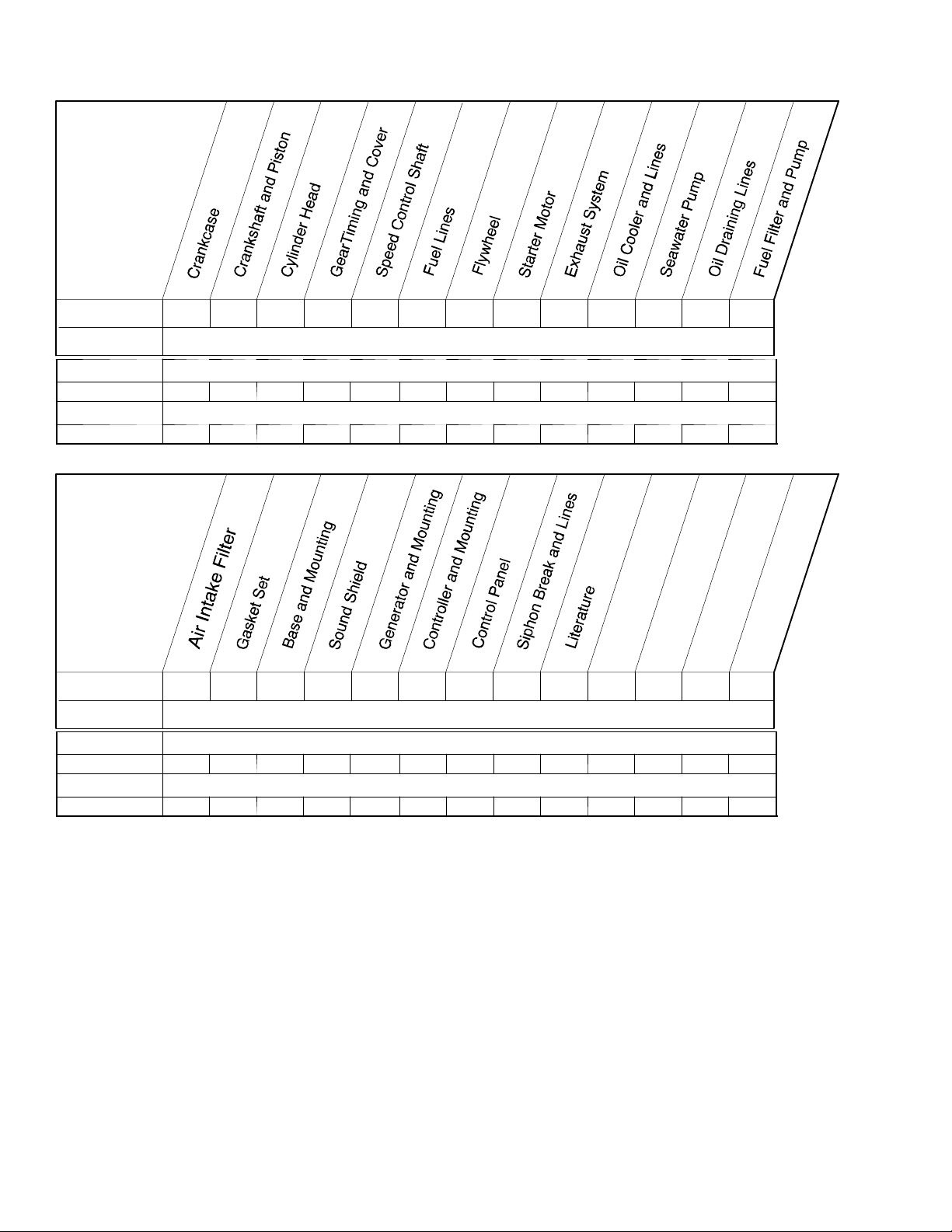
Specification Number Index
Group Title
Group No. 1 2 3 4 5 6 7 8 9 10 11 12 13
Spec. No.
VARIATION NUMBER
3.5EFOZ
GM20642-SA1 1 2 1 1 1 1 1 1 1 1 1 1 1
4EOZ
GM20641-SA1 1 1 1 1 1 1 1 1 1 1 1 1 1
Group Title
GroupNo. 141516171819202122
Spec No.
VARIATION NUMBER
3.5EFOZ
GM20642-SA1 1 1 1 1 2 2 1 1 1
4EOZ
GM20641-SA1 1 1 1 1 1 1 1 1 1
2
TP-6138 5/02
Page 5
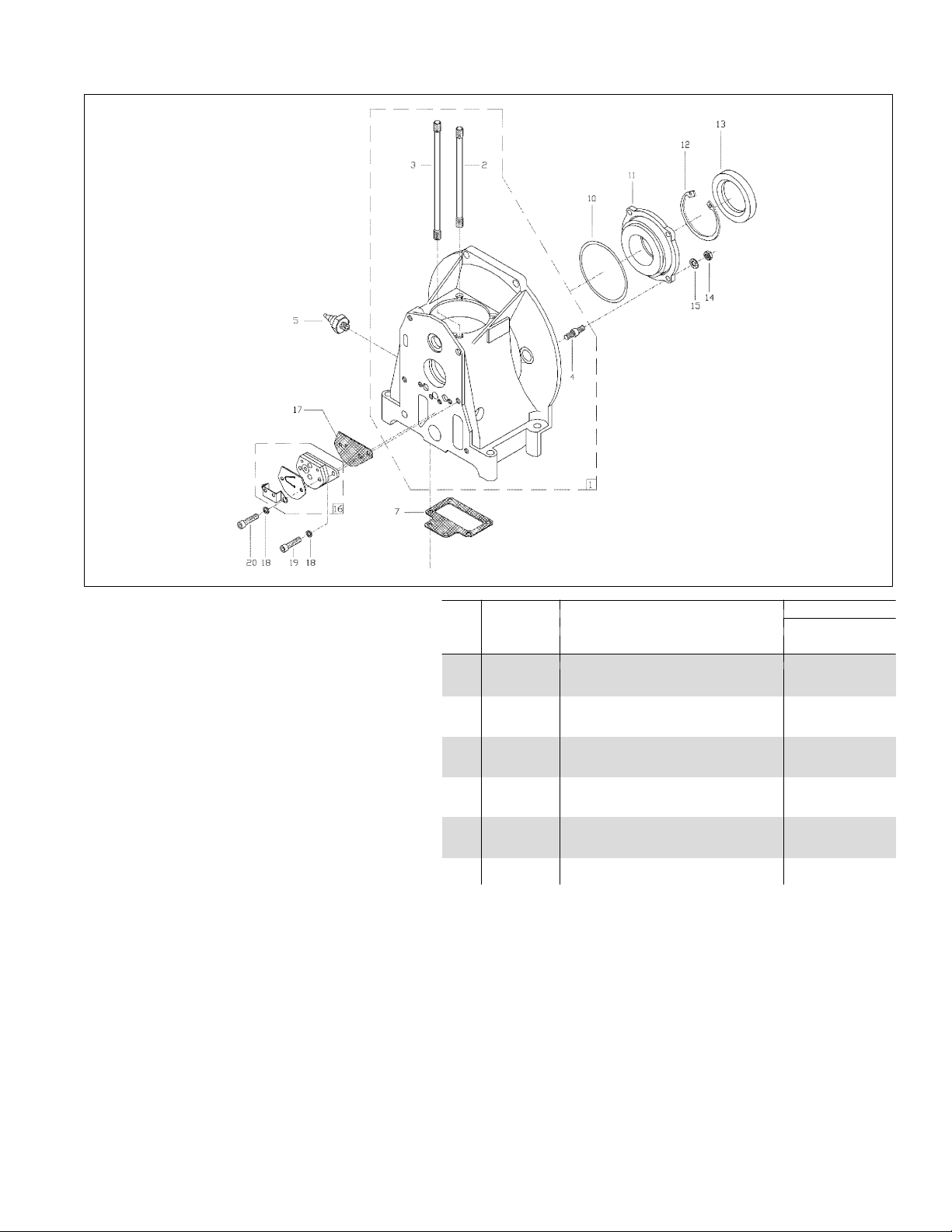
Group 1: Crankcase
Quantity
Part Variation No.
Item Number Description 1
1 GM24007 Crankcase Assembly 1
2 GM23884 Stud, Cylinder Block 2
3 GM23885 Stud, Cylinder Block 2
4 GM23886 Stud, Crankcase 4
5 GM23870 Switch, Oil Pressure 1
7 GM23934 Gasket, Crankcase 1
10 GM23955 O-ring, 99 x 3 mm 1
11 GM23927 Housing, Main Bearing 1
12 GM23965 Retainer, Ring 1
13 GM23973 Seal, Oil, 60 x 80 x 8 mm 1
14 # Nut, Hex Head, M8 4
15 # Washer, Tooth, 18 mm 4
16 GM23925 Pump Assembly, Oil 1
17 GM23937 Gasket, Oil Pump 1
18 # Washer, Split, 6 mm ID 3
19 # Screw, Hex Head Cap, M6 x 20 1
20 # Screw, Hex Head Cap, M6 x 30 2
# Common hardware; procure locally.
6138_1
TP-6138 5/02
3
Page 6
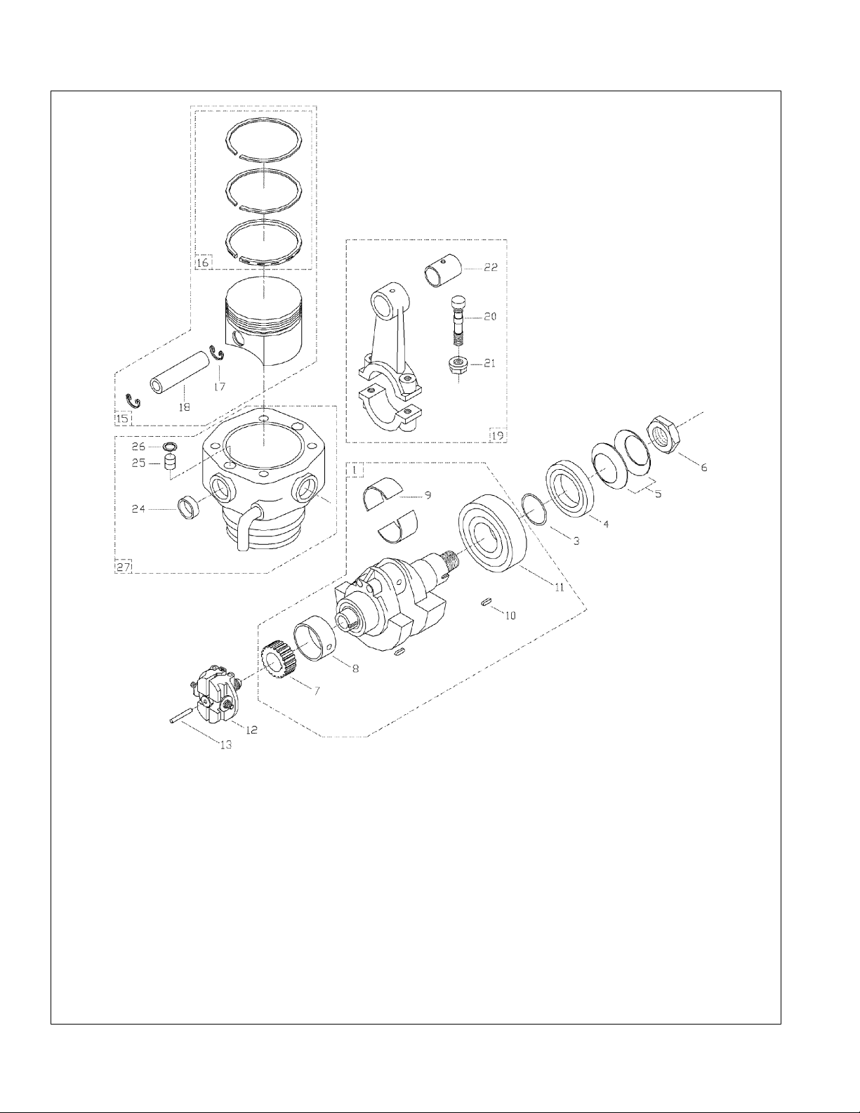
Group 2: Crankshaft and Piston
6138_2
4
TP-6138 5/02
Page 7

Group 2: Crankshaft and Piston
Quantity
Part Variation No.
Item Number Description 1 2
1 GM24009 Crankshaft Assembly 1 1
3 GM23954 O-ring, 32 x 2 mm 1 1
4 GM23893 Ring, Angle 1 1
5 GM23946 Washer, Spring, 52 x 36 x 1.2 mm 2 2
6 GM23891 Nut, Flywheel 1 1
7 GM23879 Gear, Timing Crankshaft 1 1
8 GM23942 Bushing, Main (Standard) 1 1
8 GM23943 Bushing, Main (0.25 mm Undersize) 1 1
8 GM23944 Bushing, Main (0.50 mm Undersize) 1 1
9 GM24000 Bearing (Standard) 1 1
9 GM24001 Bearing (0.25 mm Undersize) 1 1
9 GM24002 Bearing (0.50 mm Undersize) 1 1
10 GM23975 Key,6x4x12mm 2 2
11 GM23945 Bearing, Main 1 1
12 GM23906 Governor Assembly (RPM=3000E) 1
12 GM23907 Governor Assembly (RPM=3000) 1
12 GM23908 Governor Assembly (RPM=3600E) 1
13 GM23974 Pin, 4 x 27.8 mm 1 1
15 GM24010 Piston Assembly 1 1
16 GM24006 Set, Piston Ring 1 1
17 GM23983 Clip, Piston Pin 2 2
18 GM23874 Pin, Piston 1 1
19 GM23926 Rod Assembly, Connecting 1 1
20 GM23883 Bolt, Connecting Rod 2 2
21 GM23890 Nut, Collar 2 2
22 GM23882 Bushing, Connecting Rod 1 1
24 # Plug, 22 mm 4 4
25 GM23997 Connector, Water Tube 2 2
26 GM23953 O-ring, 10 x 2.2 mm 2 2
27 GM24011 Cylinder Assembly 1 1
# Common hardware; procure locally.
TP-6138 5/02
5
Page 8
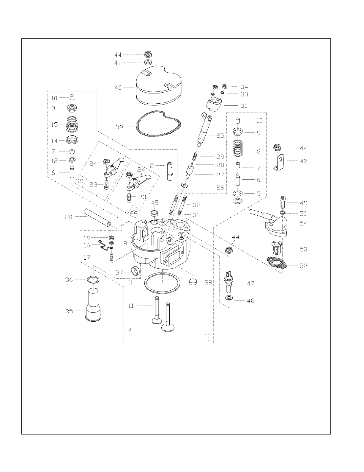
Group 3: Cylinder Head
6138_3
6
TP-6138 5/02
Page 9

Group 3: Cylinder Head
Quantity
Part Variation No.
Item Number Description 1
1 GM24012 Head Assembly, Cylinder 1
2 GM23921 Valve, Breather 1
3 GM23941 Gasket, Cylinder Head 1
4 GM23878 Valve, Intake 1
5 GM23990 Washer 2
6 GM23876 Guide, Valve 2
7 GM23964 Guide, Oil Seal 2
8 GM23947 Spring, Valve 1
9 GM23895 Retainer, Valve Spring 2
10 GM24005 Valve, Cotter 2
11 GM23877 Valve, Exhaust 1
12 GM23894 Ring 1
14 GM23911 Rotocap, Valve 1
15 GM23948 Spring, Valve 1
16 GM23951 Spring, Retainer 1
17 GM23967 Stud, M5 x 10 2
18 # Washer, 5 mm ID 2
19 # Nut, Hex Head, M5 2
20 GM23872 Shaft, Rocker Arm 1
21 GM23919 Arm Assembly, Rocker 1
22 GM23918 Arm Assembly, Rocker 1
23 GM23889 Screw, Adjusting 2
24 # Nut, Hex Head, M7
25 GM23902 Injector, Fuel 1
26 GM23962 Washer 1
27 GM23903 Nozzle, Fuel Injector 1
28 GM23904 Seat, Spring 1
29 GM23905 Spring, Nozzle 1
30 GM23991 Flange, Injector 1
31 GM23972 Stud, M6 x 50 1
32 GM23971 Stud, M6 x 45 1
33 # Washer, Split, 6 mm ID 2
34 # Nut, Hex Head, M6 2
35 GM23987 Tube, Push Rod 1
36 GM23956 O-ring, 24 x 3.5 mm 1
37 # Plug, 22 mm 2
38 # Plug, 18 mm 1
39 GM23932 Gasket, Rocker Cover 1
40 GM23920 Cover, Rocker 1
41 # Washer, 5 mm ID 2
42 GM23989 Bracket, Lifting 1
44 GM23890 Nut, Collar 6
45 # Plug, 18 mm 1
47 GM23914 Switch, Temperature Alarm 1
48 GM23981 Washer, Copper, 14 mm ID 1
49 # Screw, Hex Head Cap, M8 x 20 2
50 # Washer, Split, 8 mm ID 2
52 GM23931 Gasket 2
53 GM23912 Thermostat 1
54 GM24140 Cover, Thermostat 1
# Common hardware; procure locally.
TP-6138 5/02
7
Page 10
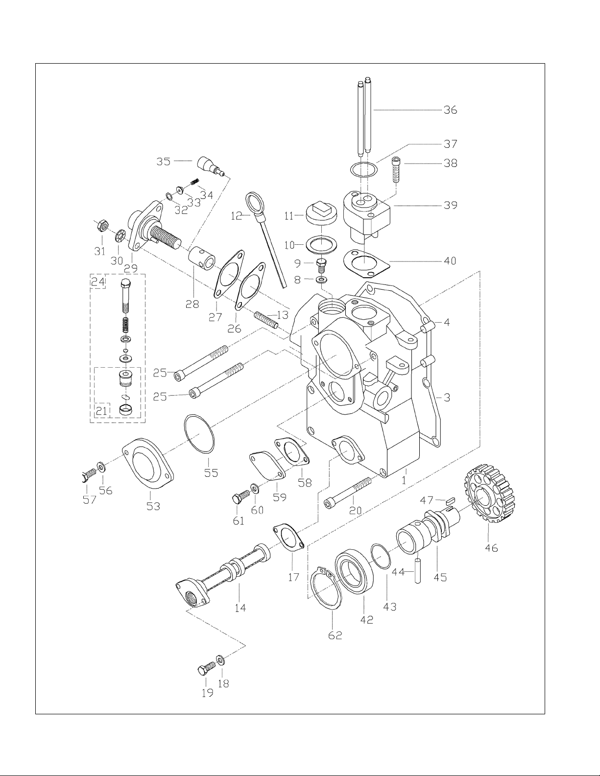
Group 4: Gear Timing and Cover
6138_4
8
TP-6138 5/02
Page 11

Group 4: Gear Timing and Cover
Quantity
Part Variation No.
Item Number Description 1
1 GM23923 Cover, Timing Gear 1
3 GM23933 Gasket, Cover 1
4 GM23976 Pin, 10 x 16 mm 2
8# Washer, Split, 5 mm ID 1
9 GM23887 Screw, Hex Head 1
10 GM23958 Gasket 1
11 GM24003 Cap, Oil Filler 1
12 GM23929 Dipstick 1
13 GM23968 Stud, M8 x 20 2
14 GM24013 Screen Assembly, Oil Filter 1
17 GM23938 Gasket, Oil Filter 1
18 GM23977 Washer, Copper, 6 mm ID 2
19 # Screw, Hex Head, M6 x 20 2
20 # Screw, Hex Head Cap, M8 x 70 2
21 GM24004 Handle 1
24 GM24008 Primer Assembly 1
25 # Screw, Hex Head Cap, M8 x 80 3
26 GM23993 Shim, Adjusting, 0.2 mm 1
26 GM23994 Shim, Adjusting, 0.5 mm 1
26 GM23995 Shim, Adjusting, 0.4 mm 1
26 GM23996 Shim, Adjusting, 1.0 mm 1
27 GM23939 Gasket 1
28 GM23901 Roller, T appet 1
29 GM23896 Pump, Fuel Injection 1
30 # Washer, Split, 8 mm ID 1
31 # Nut, Hex Head, M8 2
32 GM23897 Washer 1
33 GM23900 Valv e 1
34 GM23898 Spring, Valve 1
35 GM23899 Plunger, Fuel 1
36 GM23875 Push Rod 2
37 GM23957 O-ring, 32 x 3 mm 1
38 # Screw, Hex Head Cap, M5 x 30 2
39 GM23922 Release, Compression 1
40 GM23936 Gasket, Plate, 0.3 mm 1
40 GM23940 Gasket, Plate, 0.4 mm 1
42 GM23966 Bearing, Grooved Ball 1
43 GM23960 O-ring, 32.7 x 1.3 mm 1
44 GM23873 Bolt 1
45 GM23924 Camshaft 1
46 GM23880 Gear 1
47 GM23975 Key,6x4x12mm 1
53 GM23917 Cover 1
55 GM23961 O-ring, 57 x 2.5 mm 1
56 # Washer, Split, 6 mm ID 2
57 # Screw, Hex Head, M6 x 16 2
58 GM23930 Gasket, Plate 1
59 GM23985 Cover 1
60 GM23979 Washer, Copper, 5 mm ID 2
61 # Screw, Hex Head, M5 x 16 2
62 GM24511 Ring, snap 1
# Common hardware; procure locally.
TP-6138 5/02
9
Page 12

Group 5: Speed Control Shaft
Quantity
Part Va riation N o.
Item Number Description 1
1 GM23949 Spring, Torsion Return 1
2 GM23916 Arm, Governor 1
3 GM23888 Screw, Adjustment 1
4 GM23992 Tab, Locking 1
5# Nut, Hex Head, M6 1
6 GM23952 Retainer 1
7 GM23871 Shaft, Speed Control 1
8 GM23953 O-ring, 10 x 2.2 mm 1
9 GM23950 Spring, Torsion Return 1
10 GM23986 Plate, Control 1
11 GM23984 Lever 1
12 # Washer, Tooth, 8 mm 1
13 # Nut, Hex Head, M8 1
14 GM23913 Bolt 1
# Common hardware; procure locally.
6138_5
10
TP-6138 5/02
Page 13
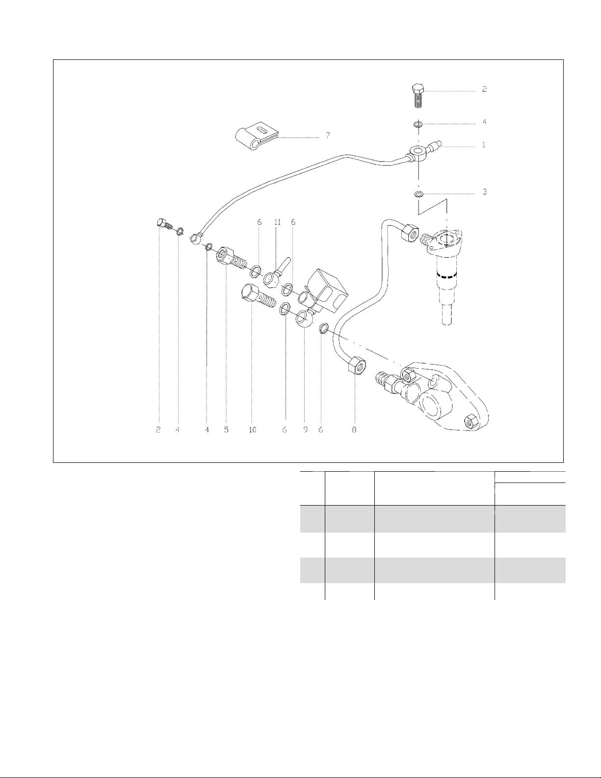
Group 6: Fuel Lines
X-6288-1
TP-6138 5/02
6138_6
Quantity
Part Variation No.
Item Number Description 1
1 GM23999 Line, Return Fuel 1
2 GM23982 Bolt, Banjo Union 2
3 GM23959 Washer, Copper, 8 mm ID 1
4 GM23978 Washer, Copper, 8 mm ID 3
5 GM23892 Connector 1
6 GM23980 Washer, Copper, 12 mm ID 4
7 GM23988 Clamp, Fuel Line 1
8 GM23998 Pipe, Fuel Injector 1
9 GM24072 Solenoid, Shutoff 1
10 GM24099 Bolt, Banjo Union 1
11 # Eye, Fuel Supply Line 1
# Common hardware; procure locally.
11
Page 14
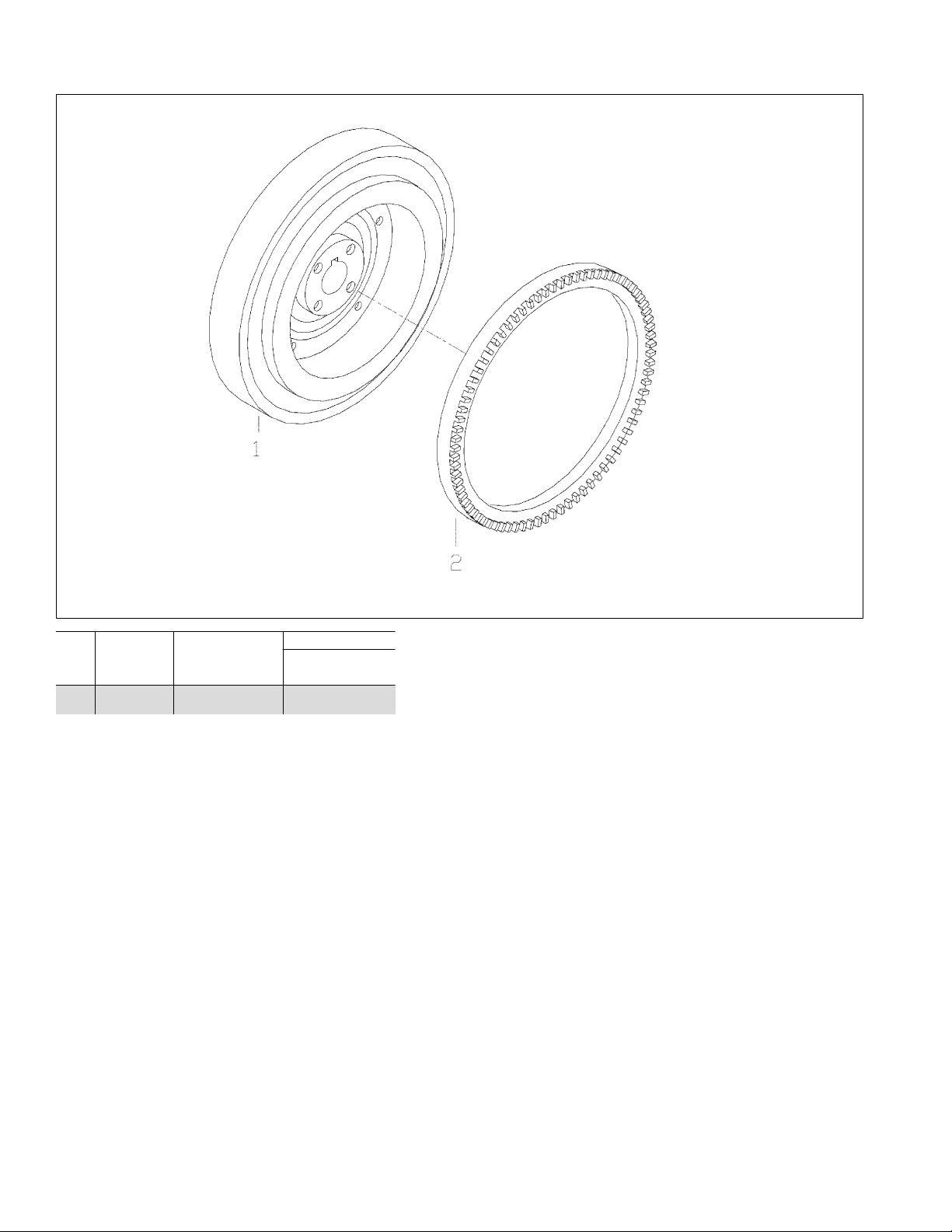
Group 7: Flywheel
Quantity
Part Va riation N o.
Item Number Description 1
1 GM23928 Flywheel 1
2 GM23881 Gear 1
# Common hardware; procure locally.
6138_7
12
TP-6138 5/02
Page 15

Group 8: Starter Motor
TP-6138 5/02
6138_8
Quantity
Part Variation No.
Item Number Description 1
1 GM23910 Starter Assembly, 12 Volt 1
2 # Screw, Hex Head Cap, M8 x 20 4
3 GM24083 Plate, Connecting 1
4 GM24109 Spacer 3
5# Washer, Tooth, 8 mm ID 4
6 GM24097 Housing, Flywheel 1
7 GM23909 Bushing 1
8 GM23969 Stud, M10 x 25 3
9 GM23970 Stud, M10 x 25 1
10 # Washer, Spring, 10 mm ID 4
11 # Nut, Hex Head, M10 4
# Common hardware; procure locally.
13
Page 16

Group 9: Exhaust System
Quantity
Part Variation No.
Item Number Description 1
1 GM24074 Tube, Mixing 1
2 # Washer, Plain, 8 mm ID 2
3 # Washer, Split, 8 mm ID 2
4# Screw, Hex Head Cap, M8 x 55 2
5 GM24021 Clamp, Hose 8
6 GM24120 Hose 1
7 GM24103 Nipple 1
8 GM24512 Hose 1
9 GM24119 Adapter, Rubber Tube 1
10 GM24063 Hose 1
11 GM24051 Switch, Temperature Alarm 1
12 # Washer, Tooth, 3 mm ID 2
13 # Screw, Round Phillips Head, M3 X 6 1
14 GM23935 Gasket 1
15 # Plug, Cap, 1/8 1
16 GM24124 Hose 1
# Common hardware; procure locally.
14
6138_9
TP-6138 5/02
Page 17

Group 10: Oil Cooler and Lines
TP-6138 5/02
6138_10
Quantity
Part Variation No.
Item Number Description 1
1 GM24114 Element, Oil Cooler 1
2 GM24112 Elbow 2
3 # Washer, T ooth, 6 mm ID 6
4# Screw, Hex Head Cap, M6 x 30 6
5 GM24021 Clamp, Hose 8
6 GM24121 Hose 1
7 GM24104 Tube 1
8 GM24122 Hose 1
9 GM24118 Hose 1
10 GM24116 Hose 1
11 GM24027 Adapter, Rubber Hose 3
12 GM24102 Tube 1
# Common hardware; procure locally.
15
Page 18

Group 11: Seawater Pump
Note: Item 1, Seawater
pump does not include items
2 and 5.
Quantity
Part Variation No.
Item Number Description 1
1 GM24052 Pump Assembly, Seawater 1
2 GM24106 Shaft, Seawater Pump 1
3 GM24032 Seal 1
4 GM24053 Housing, Seawater Pump 1
5# Screw, Hex Head Cap, M5 x 40 3
6 GM24031 O-ring 1
7 GM20852 Impeller 1
8 GM24054 Cover, Seawater Pump 1
9 # Screw, Hex Head, M4 x 8 4
# Common hardware; procure locally.
6138_11
16
TP-6138 5/02
Page 19

Group 12: Oil Draining Lines
TP-6138 5/02
6138_12
Quantity
Part Variation No.
Item Number Description 1
1 GM24143 Bushing, Reducer 1
2 GM23980 Washer, Copper, 12 mm ID 2
3 GM24142 Eye, Banjo Union 1
4 GM24141 Bolt, Banjo Union 1
5 GM24020 Clamp, Hose 2
6 GM24117 Hose, Oil Draining 1
7 GM2 4111 Adapter , Rubber Hose 1
8 GM24113 Plug, M8 x 10 1
9 GM24513 Clip, hose 1
# Common hardware; procure locally.
17
Page 20

Group 13: Fuel Filter and Pump
Quantity
Part Va riation N o.
Item Number Description 1
1 GM24125 Hose, Fuel 1
2 GM24020 Clamp, Hose 8
3 GM20850 Filter, Fuel 1
4 GM24126 Hose, Fuel Supply 2
5 GM24055 Pump, Fuel 1
6# Washer, Plain, 6 mm ID 2
7 # Washer, Split, 6 mm ID 2
8 # Screw, Hex Head, M6 x 16 2
9 GM24127 Hose, Fuel Return 1
10 GM24025 Adapter, Fuel Hose 2
11 GM24024 Connector, Fuel Hose 2
12 # Plug, 1/4 NPT 2
# Common hardware; procure locally.
18
6138_13
TP-6138 5/02
Page 21

Group 14: Air Intake Filter
Quantity
Part Variation No.
Item Number Description 1
1 GM24073 Screen, Air Intake 1
2 # Washer, Plain , 8 mm ID 2
3 # Washer,Split,8mmID 2
4# Screw, Hex Head, M8 x 25 2
5 GM20848 Screen 1
6# Washer, Plain, 5 mm ID 2
7 # Washer, Split, 5 mm ID 2
8 # Screw, Hex Head, M5 x 12 2
9 # Washer, T ooth, 5 mm ID 6
10 # Screw, Hex Head, M5 x 25 6
11 GM24144 Hose, Air Intake 1
12 GM24022 Clamp, Hose 1
13 GM23935 Gasket 1
# Common hardware; procure locally.
6138_14
TP-6138 5/02
19
Page 22

Group 15: Gasket Set
20
6138_15
TP-6138 5/02
Page 23

Group 15: Gasket Set
Quantity
Part Variation No.
Item Number Description 1
1 GM24014 Set, Gasket 1
2 GM23934 Gasket, Crankcase 1
3 GM23955 O-ring, 99 x 3 mm 1
4 GM23937 Gasket, Oil Pump 1
5 GM23954 O-ring, 32 x 2 mm 1
6 GM23953 O-ring, 10 x 2.2 mm 3
7 GM23941 Gasket, Cylinder Head 1
8 GM23962 Washer 1
9 GM23956 O-ring, 24 x 3.5 mm 1
10 GM23932 Gasket, Rocker Cover 1
11 # Washer, 5 mm ID 2
12 GM23931 Gasket 2
13 GM23933 Gasket, Cover 1
14 GM23939 Gasket 1
15 GM23979 Washer, Copper, 5 mm ID 2
16 GM23958 Gasket 1
17 GM23938 Gasket, Oil Filter 1
18 GM23977 Washer, Copper, 6 mm ID 2
19 GM23957 O-ring, 32 x 3 mm 1
20 GM23936 Gasket,Plate,0.3mm 1
21 GM23940 Gasket,Plate,0.4mm 1
22 GM23960 O-ring, 32.7 x 1.3 mm 1
23 GM23961 O-ring, 57 x 2.5 mm 1
24 GM23930 Gasket, Plate 1
25 GM23959 Washer, Copper, 8 mm ID 1
26 GM23963 Washer, Copper, 8 mm ID 3
27 GM23935 Gasket 2
28 GM23981 Washer, Copper, 14 mm ID 1
29 GM23980 Washer, Copper, 12 mm ID 6
30 GM24029 O-Ring 1
# Common hardware; procure locally.
TP-6138 5/02
21
Page 24

Group 16: Base and Mounting
22
6138_16
TP-6138 5/02
Page 25

Group 16: Base and Mounting
Quantity
Part Variation No.
Item Number Description 1
1 GM24080 Tray 1
2 GM24044 Vibromount 4
3 # Washer, Plain 6
4# Washer, Split, 8 mm ID 11
5# Nut, Hex Head , M8 8
6# Screw, Hex Head, M10 x 70 4
7 GM24047 Ring, Rubber 2
8 GM24078 Bracket, Engine Right 1
9 GM24110 Spacer 2
10 GM24046 Bushing, Rubber 2
11 # Washer, Plain, 10 mm ID 4
12 # Washer, Split, 10 mm ID 6
13 # Nut, Hex Head, M10 6
14 # Screw, Hex Head, M8 x 40 2
15 GM24079 Bracket, Engine Left 1
16 # Washer, Tooth, 8 mm ID 4
17 GM24056 Strap, Ground 1
18 # Screw, Hex Head, M8 x 20 2
19 # Washer, Plain, 8 mm ID 1
20 GM24084 Bracket, Generator 1
21 # Screw, Hex Head , M10 x 25 2
22 GM24115 Base 1
23 GM24139 Plate, Sound Shield 1
# Common hardware; procure locally.
TP-6138 5/02
23
Page 26

Group 17: Sound Shield
24
6138_17
TP-6138 5/02
Page 27

Group 17: Sound Shield
Par
t
Part Quantity
Variation No.
Number
Item
1 GM24159 Junction, Corner 4
2 GM24145 Mounting, Upper Rear 1
3 GM24148 Mounting, Upper Front 1
4 GM24146 Mounting, Upper Left, Right 2
5 GM24147 Mounting, Vertical 4
6 GM24019 Clip 10
7 # Screw, Self-Threading 8
8 GM24095 Housing, Electrical Board 1
9 GM24094 Plate, Connecting 1
10 GM24089 Panel, Electrical Board 1
11 GM24077 Base, Sound Shield Front 1
12 GM24160 Stud, Coupling 12
13 GM24035 Grommet 5
14 GM24088 Panel, Left Removable 1
15 GM24090 Panel, Top Removable 1
16 GM24087 Panel, Right Removable 1
17 GM24082 Base, Sound Shield Right 1
18 # Screw, Hex Head, M6 x 20 8
19 # Washer, Plain, 6 mm ID 8
20 # Screw, Flat Phillips Head, M6 x 45 10
21 GM24158 Latch 6
22 GM24086 Panel, Front, Rear 2
23 GM24076 Base, Sound Shield Rear 1
24 GM24081 Base, Capacitor 1
25 GM24075 Base, Sound Shield Left 1
26 GM24096 Cover, Grooved 2
27 # Screw, Round Phillips Head, M5 x 14 2
28 # Washer, Tooth, 5 mm ID 1
29 GM24039 Grommet 1
30 GM24041 Grommet 1
31 GM24042 Plug 2
32 GM24037 Grommet 1
33 GM24022 Clamp, Hose 2
34 GM24123 Tube, Exhaust 1
35 GM24107 Elbow, Exhaust Tube, 40/50 mm OD 1
35 GM24108 Elbow, Exhaust Tube, 40 mm OD 1
36 GM24048 Rivet 13
Items Not Shown
GM24017 Nut, Jaw, M6 8
GM24018 Nut, Jaw, M8 4
GM24049 Gasket, Adhesive, 20 mm wide x 3 mm high
GM24050 Gasket, Adhesive, 30 mm wide x 3 mm high
GM24128 Gasket, Sealing T ar Base Front, Rear 2
GM24129 Gasket, Sealing T ar Base Right, Left 2
GM24130 Foam, Acoustic Front Base 1
GM24130 Foam, Acoustic Front Base 2
GM24131 Foam, Acoustic Rear Base 1
GM24132 Foam, Acoustic Left Base 1
GM24133 Foam, Acoustic Right Base 1
GM24134 Foam, Acoustic Left Panel 1
GM24135 Foam, Acoustic Control Panel 1
GM24136 Foam, Acoustic Right Panel 1
GM24137 Foam, Acoustic Top Panel 1
GM24138 Foam, Acoustic Upper and Vertical Mounting 1
# Common hardware; procure locally.
Description 1
TP-6138 5/02
25
Page 28

Group 18: Generator and Mounting
26
6138_18
TP-6138 5/02
Page 29

Group 18: Generator and Mounting
Quantity
Part Variation No.
Item Number Description 1 2
1 GM24070 Alternator, Engine Charging 1 1
2 GM24085 Bracket, Lifting 1 1
3 GM24100 Hub, Engine-Stator Connection 1 1
4# Washer, Special Notch, 8 mm ID 4 4
5# Screw, Hex Head, M8 x 35 4 4
6 GM24101 Stud 1 1
7 GM24065 Varistor 2 2
8 GM24066 Diode 2 2
9 GM24151 Rotor Assembly 1 1
10 GM24033 Bearing 1 1
11 GM24149 Stator Assembly, 50 Hz 1
11 GM24150 Stator Assembly, 60 Hz 1
12 GM24028 Bushing, Reducing, 3/8-1/4 1 1
13 GM20853 Plug, Zinc Electrode 1 1
14 # Washer, Plain, 10 mm ID 4 4
15 # Screw, Hex Head, M10 x 140 4 4
16 GM24030 O-ring 1 1
17 GM24091 Cover 1 1
18 # Washer, Tooth, 5 mm ID 2 2
19 # Screw, Hex Head, M5 x 12 2 2
20 # Plug, 3/8 1 1
21 # Plug, M10 1 1
22 # Screw, Flat Head Cap, M6 x 16 3 3
23 # Washer, Split, 6 mm ID 3 3
23 # Screw, Hex Head Cap , M8 x 55 3 3
24 # Nut, Hex Head, M6 3 3
25 # Screw, Hex Head Cap, M6 x 30 5 5
26 # Washer, Tooth, 6 mm ID 5 5
# Common hardware; procure locally.
TP-6138 5/02
27
Page 30

Group 19: Controller and Mounting
28
6138_19
TP-6138 5/02
Page 31

Group 19: Controller and Mounting
42
GM30673
Capacitor (50 Hz gen.)
1
(60 Hz gen.)
X-506-68
X-506-46
18 amp
35 amp
Quantity
Part Variation No.
Item Number Description 1 2
1 GM24098 Box, Controller 1 1
2 GM24015 Breaker, Circuit, 15 Amp 2 Pole 1
2 GM24016 Breaker, Circuit, 16 Amp 2 Pole 1
3 GM24093 Plate, Circuit Breaker 1 1
4# Screw, Round Phillips Head, M3 x 6 4 4
5# Screw, Round Phillips Head, M5 x 12 8 8
6 GM24040 Grommet 1 1
7 GM20851 Fuse, 25 Amp 1 1
8 GM24062 Carrier, Fuse 1 1
9 GM24061 Carrier, Fuse 1 1
10 GM20849 Fuse, 10 Amp 1 1
11 # Nut, Hex Head, M4 5 5
12 # Washer, Split, 4 mm ID 5 5
13 # Washer, Plain, 4 mm ID 5 5
14 # Screw, Hex Head, M4 x 16 5 5
15 GM24067 Rectifier Assembly 1 1
16 GM24092 Cover, Controller Box 1 1
17 # Nut, Hex Head, M6 4 4
18 # Washer, Plain, 6 mm ID 5 5
19 # Washer, Tooth, 6 mm ID 12 12
20 # Screw, Hex Head, M6 x 25 1 1
21 # Nut, Hex Head, M5 4 4
22 # Washer, Plain, 5 mm ID 6 6
23 # Washer, Tooth , 5 mm ID 2 2
24 # Screw, Hex Head, M5 x 20 1 1
25 # Screw, Hex Head, M5 x 10 2 2
26 GM24060 Base, Relay 3 3
27 GM24059 Relay 3 3
28 GM24064 Diode, 3 Amp , 400 Volt 3 3
29 GM24057 Base, Electrical Connection 1 1
30 GM24058 Plate, Electrical Connection 1 1
31 GM24157 Harness, Control Box 1 1
32 GM24153 Harness, Control Box to Engine 1 1
33 GM24154 Harness, Engine 1 1
34 GM24155 Harness, Control Box to Panel 1 1
35 GM24045 Vibromount 4 4
36 GM24036 Grommet 1 1
37 GM24038 Grommet 1 1
38 GM24071 Voltage Regulator 1 1
39 # Washer, Plain, 6 mm ID 2 2
40 # Screw, Hex Head, M6 x 20 2 2
41 # Nut, Collar, M6 4 4
42 GM24068 Capacitor 1 1
43 # Washer, Tooth , 8 mm ID 1 1
44 # Nut, Hex Head , M8 1 1
45 GM24043 Protector, Rubber 1 1
# Common hardware; procure locally.
TP-6138 5/02
29
Page 32

Group 20: Control Panel
Par
t
Control Box Harness
GM34930
Part
Number
Item
1 GM24161 Panel, Control 1
2 # Screw, Flat Phillips Head, M3 x 12 4
3 GM24069 Connector 1
4 GM24156 Connector to Remote Start/Stop Switch Harness 1
5 GM24152 Connector to Remote Control Panel Harness 1
6# Nut, Hex Head, M3 2
7 # Screw, Special Head, M3 x 12 2
8 GM24034 Grommet 1
9 GM24156 Connector to Remote Start/Stop Switch Harness 1
10 GM24514 Fuse, 0.63 Amp 1
# Common hardware; procure locally.
Description 1
Variation No.
6138_20
Quantity
30
TP-6138 5/02
Page 33

Group 21: Siphon Break and Lines
Quantity
Part Variation No.
Item Number Description 1
1 PA-229928 Kit, Siphon Break 1
2 GM24021 Clamp, Hose 4
3 GM24105 Connection, Hose 2
4 GM24023 Hose 2
5 GM24035 Grommet 2
6138_21
TP-6138 5/02
31
Page 34

Group 22: Literature
Quantity
Part Variation No.
Item Number Description 1
1 TP-5620 Safety Precautions, Marine 1
2 TP-6069 I/M 3.5-150EOZ/EFOZ, Marine 1
3 TP-6134 O/M 3.5EFOZ/4EOZ, Marine 1
4 TP-6137 S/M 4EOZ/3.5EFOZ, Marine 1
5 TP-6138 P/C 4EOZ/3.5EFOZ Farymann 18W 1
6 TP-6143 O/M Farymann 18W 1
7 TP-6149 Warranty, 4EOZ/3.5EFOZ, Marine 1
8 TP-6163 S/M Farymann 18W (903.04.08 1.5) 1
Paint and Miscellaneous Parts
Paint, White, Gallon 221334
Paint, White, Spray Can 221335
Paint, White, .75 oz. Bottle w/Brush GM19490
Accessories
Qty. Description Part No.
Harness, Control Wiring to Plug
(Remote Start) GM22474-KP1
1 Harness, Wiring GM22474
Harness, Remote Panel, 15 Ft. PA-249334
1 Harness, Wiring Extension 249334
Harness, Remote Panel, 25 Ft. PA-249336
1 Harness, Wiring Extension 249336
Panel, Remote Start PA-359581
1 Decal, Warning 249494
1 Installation Instructions, Remote Start Panel TT-1245
1 Panel Assembly (includes the following) A-226965
1 Panel, Control 226964
1 Harness, Wiring 226979
1 Meter, Run Time 238736
1 Switch, Rocker 344039
2 Screw, Pan Head, M3 x 12 M7982A-03012-20
2 Nut, Hex, 3 mm M934-03-50
2 Washer, Lock, .146 ID x .285 in. OD X-22-6
Harness, Remote (for GM20770-KP1), 25 Ft. GM20971-KP1
1 Cable, RS-232 GM23202
Panel, Remote Start GM20770-KP1
1 Panel Assembly, Remote GM0768
Ship-to-Shore Switch PAA-246617
1 Switch, Transfer A-246617
1 Installation Instructions, Ship-to-Shore Transfer Switch TT-535
Strainer, Seawater PA-359579
1 Filter, Water, 1/2 x 1/2 in. NPT X-661-1
32
TP-6138 5/02
Page 35

Appendix A Abbreviations
The following list contains abbreviations that may appear in this publication.
A, amp ampere
ABDC after bottom dead center
AC alternating current
A/D analog to digital
ADC analog to digital converter
adj. adjust, adjustment
ADV advertising dimensional
AHWT anticipatory high water
AISI American Iron and Steel
ALOP anticipatory low oil pressure
alt. alternator
Al aluminum
ANSI American National Standards
AO anticipatory only
API American Petroleum Institute
approx. approximate, approximately
AR as required, as requested
AS as supplied, as stated, as
ASE American Society of Engineers
ASME American Society of
assy. assembly
ASTM American Society for Testing
ATDC after top dead center
ATS automatic transfer switch
auto. automatic
aux. auxiliary
A/V audiovisual
avg. average
AVR automatic voltage regulator
AWG American Wire Gauge
AWM appliance wiring material
bat. battery
BBDC before bottom dead center
BC battery charger, battery
BCA battery charging alternator
BCI Battery Council International
BDC before dead center
BHP brake horsepower
blk. black (paint color), block
blk. htr. block heater
BMEP brake mean effective pressure
bps bits per second
br. brass
BTDC before top dead center
Btu British thermal unit
Btu/min. British thermal units per minute
C Celsius, centigrade
cal. calorie
CARB California Air Resources Board
CB circuit breaker
cc cubic centimeter
CCA cold cranking amps
ccw. counterclockwise
CEC Canadian Electrical Code
cert. certificate, certification, certified
cfh cubic feet per hour
drawing
temperature
Institute
Institute
(formerly American Standards
Association, ASA)
suggested
Mechanical Engineers
Materials
charging
(engine)
cfm cubic feet per minute
CG center of gravity
CID cubic inch displacement
CL centerline
cm centimeter
CMOS complementary metal oxide
cogen. cogeneration
com communications (port)
coml commercial
Coml/Rec Commercial/Recreational
conn. connection
cont. continued
CPVC chlorinated polyvinyl chloride
crit. critical
CRT cathode ray tube
CSA Canadian Standards
CT current transformer
Cu copper
cu. in. cubic inch
cw. clockwise
CWC city water-cooled
cyl. cylinder
D/A digital to analog
DAC digital to analog converter
dB decibel
dBA decibel (A weighted)
DC direct current
DCR direct current resistance
deg., ° degree
dept. department
dia. diameter
DI/EO dual inlet/end outlet
DIN Deutsches Institut fur Normung
DIP dual inline package
DPDT double-pole, double-throw
DPST double-pole, single-throw
DS disconnect switch
DVR digital voltage regulator
E, emer. emergency (power source)
EDI electronic data interchange
EFR emergency frequency relay
e.g. for example (exempli gratia)
EG electronic governor
EGSA Electrical Generating Systems
EIA Electronic Industries
EI/EO end inlet/end outlet
EMI electromagnetic interference
emiss. emission
eng. engine
EPA Environmental Protection
EPS emergency power system
ER emergency relay
ES engineering special,
ESD electrostatic discharge
est. estimated
E-Stop emergency stop
etc. et cetera (and so forth)
substrate (semiconductor)
Association
e. V.
(also Deutsche Industrie
Normenausschuss)
Association
Association
Agency
engineered special
exh. exhaust
ext. external
F Fahrenheit, female
fglass. fiberglass
FHM flat head machine (screw)
fl. oz. fluid ounce
flex. flexible
freq. frequency
FS full scale
ft. foot, feet
ft. lbs. foot pounds (torque)
ft./min. feet per minute
ggram
ga. gauge (meters, wire size)
gal. gallon
gen. generator
genset generator set
GFI ground fault interrupter
GND,
gov. governor
gph gallons per hour
gpm gallons per minute
gr. grade, gross
GRD equipment ground
gr. wt. gross weight
H x W x D height by width by depth
HC hex cap
HCHT high cylinder head temperature
HD heavy duty
HET high exhaust temperature,
hex hexagon
Hg mercury (element)
HH hex head
HHC hex head cap
HP horsepower
hr. hour
HS heat shrink
hsg. housing
HVAC heating, ventilation, and air
HWT high water temperature
Hz hertz (cycles per second)
IC integrated circuit
ID inside diameter, identification
IEC International Electrotechnical
IEEE Institute of Electrical and
IMS improved motor starting
in. inch
in. H
in. Hg inches of mercury
in. lbs. inch pounds
Inc. incorporated
ind. industrial
int. internal
int./ext. internal/external
I/O input/output
IP iron pipe
ISO International Organization for
J joule
JIS Japanese Industry Standard
ground
high engine temperature
conditioning
Commission
Electronics Engineers
O inches of water
2
Standardization
TP-6138 5/02 Appendix A-1
Page 36

k kilo (1000)
K kelvin
kA kiloampere
KB kilobyte (2
kg kilogram
2
kg/cm
kgm kilogram-meter
kg/m
kilograms per square
centimeter
3
kilograms per cubic meter
10
bytes)
kHz kilohertz
kJ kilojoule
km kilometer
kOhm, kW kilo-ohm
kPa kilopascal
kph kilometers per hour
kV kilovolt
kVA kilovolt ampere
kVAR kilovolt ampere reactive
kW kilowatt
kWh kilowatt-hour
kWm kilowatt mechanical
L liter
LAN local area network
L x W x H length by width by height
lb. pound, pounds
3
lbm/ft
pounds mass per cubic feet
LCB line circuit breaker
LCD liquid crystal display
ld. shd. load shed
LED light emitting diode
Lph liters per hour
Lpm liters per minute
LOP low oil pressure
LP liquefied petroleum
LPG liquefied petroleum gas
LS left side
L
wa
sound power level, A weighted
LWL low water level
LWT low water temperature
m meter, milli (1/1000)
M mega (10
3
m
3
m
units), male
cubic meter
/min. cubic meters per minute
6
when used with SI
mA milliampere
man. manual
max. maximum
MB megabyte (2
20
bytes)
MCM one thousand circular mils
MCCB molded-case circuit breaker
meggar megohmmeter
MHz megahertz
mi. mile
mil one one-thousandth of an inch
min. minimum, minute
misc. miscellaneous
MJ megajoule
mJ millijoule
mm millimeter
mOhm, mW
milliohm
MOhm, MW
megohm
MOV metal oxide varistor
MPa megapascal
mpg miles per gallon
mph miles per hour
MS military standard
m/sec. meters per second
MTBF mean time between failure
MTBO mean time between overhauls
mtg. mounting
MW megawatt
mW milliwatt
mF microfarad
N, norm. normal (power source)
NA not available, not applicable
nat. gas natural gas
NBS National Bureau of Standards
NC normally closed
NEC National Electrical Code
NEMA National Electrical
Manufacturers Association
NFPA National Fire Protection
Association
Nm newton meter
NO normally open
no., nos. number, numbers
NPS National Pipe, Straight
NPSC National Pipe, Straight-coupling
NPT National Standard taper pipe
thread per general use
NPTF National Pipe, Taper-Fine
NR not required, normal relay
ns nanosecond
OC overcrank
OD outside diameter
OEM original equipment
manufacturer
OF overfrequency
opt. option, optional
OS oversize, overspeed
OSHA Occupational Safety and Health
Administration
OV overvoltage
oz. ounce
p., pp. page, pages
PC personal computer
PCB printed circuit board
pF picofarad
PF power factor
ph., Æ phase
PHC Phillips head crimptite (screw)
PHH Phillips hex head (screw)
PHM pan head machine (screw)
PLC programmable logic control
PMG permanent-magnet generator
pot potentiometer, potential
ppm parts per million
PROM programmable read-only
memory
psi pounds per square inch
pt. pint
PTC positive temperature coefficient
PTO power takeoff
PVC polyvinyl chloride
qt. quart, quarts
qty. quantity
R replacement (emergency)
power source
rad. radiator, radius
RAM random access memory
RDO relay driver output
ref. reference
rem. remote
Res/Coml Residential/Commercial
RFI radio frequency interference
RH round head
RHM round head machine (screw)
rly. relay
rms root mean square
rnd. round
ROM read only memory
rot. rotate, rotating
rpm revolutions per minute
RS right side
RTV room temperature vulcanization
SAE Society of Automotive
Engineers
scfm standard cubic feet per minute
SCR silicon controlled rectifier
s, sec. second
SI Systeme international d’unites,
International System of Units
SI/EO side in/end out
sil. silencer
SN serial number
SPDT single--pole, double--throw
SPST single--pole, single--throw
spec, specs
specification(s)
sq. square
sq. cm square centimeter
sq. in. square inch
SS stainless steel
std. standard
stl. steel
tach. tachometer
TD time delay
TDC top dead center
TDEC time delay engine cooldown
TDEN time delay emergency to
normal
TDES time delay engine start
TDNE time delay normal to
emergency
TDOE time delay off to emergency
TDON time delay off to normal
temp. temperature
term. terminal
TIF telephone influence factor
TIR total indicator reading
tol. tolerance
turbo. turbocharger
typ. typical (same in multiple
locations)
UF underfrequency
UHF ultrahigh frequency
UL Underwriter’s Laboratories, Inc.
UNC unified coarse thread (was NC)
UNF unified fine thread (was NF)
univ. universal
US undersize, underspeed
UV ultraviolet, undervoltage
V volt
VAC volts alternating current
VAR voltampere reactive
VDC volts direct current
VFD vacuum fluorescent display
VGA video graphics adapter
VHF very high frequency
W watt
WCR withstand and closing rating
w/ with
w/o without
wt. weight
xfmr transformer
TP-6138 5/02A-2 Appendix
Page 37

Appendix B Common Hardware Application Guidelines
Use the information below and on the following pages to
identify proper fastening techniques when no specific
reference for reassembly is made.
Bolt/Screw Length: When bolt/screw length is not given,
use Figure 1 as a guide. As a general rule, a minimum
length of one thread beyond the nut and a maximum
length of 1/2 the bolt/screw diameter beyond the nut is
the preferred method.
Washers and Nuts: Use split lock washers as a bolt
locking device where specified. Use SAE flat washers
with whiz nuts, spiralock nuts, or standard nuts and
preloading (torque) of the bolt in all other applications.
See Appendix C, General Torque Specifications, and
other torque specifications in the service literature.
Preferred Nut/Bolt Clearance
1
2
Steps for common hardware application:
1. Determine entry hole type: round or slotted.
2. Determine exit hole type: fixed female thread (weld
nut), round, or slotted.
For round and slotted exit holes, determine if
hardware is greater than 1/2 inch in diameter, or
1/2 inch in diameter or less. Hardware that is
greater than 1/2 inch in diameter takes a standard
nut and SAE washer. Hardware 1/2 inch or less in
diameter can take a properly torqued whiz nut or
spiralock nut. See Figure 2.
3. Follow these SAE washer rules after determining
exit hole type:
a. Always use a washer between hardware and a
slot.
b. Always use a washer under a nut (see 2 above
for exception).
c. Use a washer under a bolt when the female
thread is fixed (weld nut).
Unacceptable Nut/Bolt Clearance
3
1. 1/2 of bolt diameter
2. Min. 1 full thread beyond top of nut
3. Below top of nut
Figure 1 Acceptable Bolt Lengths
G-585
4. Refer to Figure 2, which depicts the preceding
hardware configuration possibilities.
1
6
1. Cap screw
2. Entry hole types
3. Standard nut and SAE washer
4. Whiz nut or spiralock: up to 1/2 in. dia. hardware
5. Weld nuts: above 1/2 in. dia. hardware
6. Exit hole types
2
3
5
4
G-585
Figure 2 Acceptable Hardware Combinations
TP-6138 5/02 Appendix A-3
Page 38

Appendix C General Torque Specifications
T
A
lumi
A
Use the following torque specifications when service
literature instructions give no specific torque values.
The charts list values for new plated, zinc phosphate, or
American Standard Fasteners Torque Specifications
orque
Size
8-32 Nm (in. lb.) 1.8 (16) 2.3 (20) — 1.8 (16)
10-24 Nm (in. lb.) 2.9 (26) 3.6 (32) — 2.9 (26)
10-32 Nm (in. lb.) 2.9 (26) 3.6 (32) — 2.9 (26)
1/4-20 Nm (in. lb.) 6.8 (60) 10.8 (96) 14.9 (132) 6.8 (60)
1/4-28 Nm (in. lb.) 8.1 (72) 12.2 (108) 16.3 (144) 8.1 (72)
5/16-18 Nm (in. lb.) 13.6 (120) 21.7 (192) 29.8 (264) 13.6 (120)
5/16-24 Nm (in. lb.) 14.9 (132) 23.1 (204) 32.5 (288) 14.9 (132)
3/8-16 Nm (ft. lb.) 24.0 (18) 38.0 (28) 53.0 (39) 24.0 (18)
3/8-24 Nm (ft. lb.) 27.0 (20) 42.0 (31) 60.0 (44) 27.0 (20)
7/16-14 Nm (ft. lb.) 39.0 (29) 60.0 (44) 85.0 (63) —
7/16-20 Nm (ft. lb.) 43.0 (32) 68.0 (50) 95.0 (70) —
1/2-13 Nm (ft. lb.) 60.0 (44) 92.0 (68) 130.0 (96) —
1/2-20 Nm (ft. lb.) 66.0 (49) 103.0 (76) 146.0 (108) —
9/16-12 Nm (ft. lb.) 81.0 (60) 133.0 (98) 187.0 (138) —
9/16-18 Nm (ft. lb.) 91.0 (67) 148.0 (109) 209.0 (154) —
5/8-11 Nm (ft. lb.) 113.0 (83) 183.0 (135) 259.0 (191) —
5/8-18 Nm (ft. lb.) 128.0 (94) 208.0 (153) 293.0 (216) —
3/4-10 Nm (ft. lb.) 199.0 (147) 325.0 (240) 458.0 (338) —
3/4-16 Nm (ft. lb.) 222.0 (164) 363.0 (268) 513.0 (378) —
1-8 Nm (ft. lb.) 259.0 (191) 721.0 (532) 1109.0 (818) —
1-12 Nm (ft. lb.) 283.0 (209) 789.0 (582) 1214.0 (895) —
Measurement
Assembled into Cast Iron or Steel
Grade 2 Grade 5 Grade 8
oiled threads. Increase values by 15% for nonplated
threads. All torque values are +0%/--10%.
Assembled into
num
Grade2or5
Metric Fasteners Torque Specifications, Measured in Nm (ft. lb.)
Assembled into Cast Iron or Steel
Size (mm)
M6 x 1.00 5.6 (4) 9.9 (7) 14.0 (10) 5.6 (4)
M8 x 1.25 13.6 (10) 25.0 (18) 35.0 (26) 13.6 (10)
M8 x 1.00 21.0 (16) 25.0 (18) 35.0 (26) 21.0 (16)
M10 x 1.50 27.0 (20) 49.0 (35) 68.0 (50) 27.0 (20)
M10 x 1.25 39.0 (29) 49.0 (35) 68.0 (50) 39.0 (29)
M12 x 1.75 47.0 (35) 83.0 (61) 117.0 (86) —
M12 x 1.50 65.0 (48) 88.0 (65) 125.0 (92) —
M14 x 2.00 74.0 (55) 132.0 (97) 185.0 (136) —
M14 x 1.50 100.0 (74) 140.0 (103) 192.0 (142) —
M16 x 2.00 115.0 (85) 200.0 (148) 285.0 (210) —
M16 x 1.50 141.0 (104) 210.0 (155) 295.0 (218) —
M18 x 2.50 155.0 (114) 275.0 (203) 390.0 (288) —
M18 x 1.50 196.0 (145) 305.0 (225) 425.0 (315) —
Grade 5.8 Grade 8.8 Grade 10.9
Assembled into
luminum
Grade 5.8 or 8.8
TP-6138 5/02A-4 Appendix
Page 39

Appendix D Common Hardware Identification
Screw/Bolts/Studs
Head Styles
Hex Head or Machine Head
Hex Head or Machine Head
with Washer
Flat Head (FHM)
Round Head (RHM)
Pan Head
Hex Socket Head Cap or
Allent Head Cap
Hex Socket Head or Allent
Head Shoulder Bolt
Sheet Metal Screw
Stud
Drive Styles
Hex
Hex and Slotted
Phillipsr
Nuts
Nut Styles
Hex Head
Lock or Elastic
Square
Cap or Acorn
Wing
Washers
Washer Styles
Plain
Split Lock or Spring
Spring or Wave
External Tooth Lock
Internal Tooth Lock
Internal-External Tooth Lock
Hardness Grades
American Standard
Grade 2
Grade 5
Grade 8
Grade 8/9 (Hex Socket
Head)
Metric
Number stamped on
hardware; 5.8 shown
5.8
Slotted
Hex Socket
Allent head screw is a trademark of Holo-Krome Co.
Phillipsr screw is a registered trademark of Phillips Screw Company.
Sample Dimensions
American Standard (Screws, Bolts, Studs, and Nuts)
1/4-20 x 1
Metric (Screws, Bolts, Studs, and Nuts)
M8-1.25 x 20
Length In Inches (Screws and Bolts)
Threads Per Inch
Major Thread Diameter In Fractional Inches Or Screw Number Size
Length In Millimeters (Screws and Bolts)
Distance Between Threads In Millimeters
Major Thread Diameter In Millimeters
Plain Washers
9/32
x5/8x 1/16
Lock Washers
5/8
Thickness
External Dimension
Internal Dimension
Internal Dimension
TP-6138 5/02 Appendix A-5
Page 40

Appendix E Common Hardware List
The Common Hardware List lists part numbers and dimensions for common hardware items.
American Standard
Part No. Dimensions
Hex Head Bolts (Grade 5)
X-465-17 1/4-20 x .38
X-465-6 1/4-20 x .50
X-465-2 1/4-20 x .62
X-465-16 1/4-20 x .75
X-465-18 1/4-20 x .88
X-465-7 1/4-20 x 1.00
X-465-8 1/4-20 x 1.25
X-465-9 1/4-20 x 1.50
X-465-10 1/4-20 x 1.75
X-465-11 1/4-20 x 2.00
X-465-12 1/4-20 x 2.25
X-465-14 1/4-20 x 2.75
X-465-21 1/4-20 x 5.00
X-465-25 1/4-28 x .38
X-465-20 1/4-28 x 1.00
X-125-33 5/16-18 x .50
X-125-23 5/16-18 x .62
X-125-3 5/16-18 x .75
X-125-31 5/16-18 x .88
X-125-5 5/16-18 x 1.00
X-125-24 5/16-18 x 1.25
X-125-34 5/16-18 x 1.50
X-125-25 5/16-18 x 1.75
X-125-26 5/16-18 x 2.00
230578 5/16-18 x 2.25
X-125-29 5/16-18 x 2.50
X-125-27 5/16-18 x 2.75
X-125-28 5/16-18 x 3.00
X-125-22 5/16-18 x 4.50
X-125-32 5/16-18 x 5.00
X-125-35 5/16-18 x 5.50
X-125-36 5/16-18 x 6.00
X-125-40 5/16-18 x 6.50
X-125-43 5/16-24 x 1.75
X-125-44 5/16-24 x 2.50
X-125-30 5/16-24 x .75
X-125-39 5/16-24 x 2.00
X-125-38 5/16-24 x 2.75
X-6238-2 3/8-16 x .62
X-6238-10 3/8-16 x .75
X-6238-3 3/8-16 x .88
X-6238-11 3/8-16 x 1.00
X-6238-4 3/8-16 x 1.25
X-6238-5 3/8-16 x 1.50
X-6238-1 3/8-16 x 1.75
X-6238-6 3/8-16 x 2.00
X-6238-17 3/8-16 x 2.25
X-6238-7 3/8-16 x 2.50
X-6238-8 3/8-16 x 2.75
X-6238-9 3/8-16 x 3.00
X-6238-19 3/8-16 x 3.25
X-6238-12 3/8-16 x 3.50
X-6238-20 3/8-16 x 3.75
X-6238-13 3/8-16 x 4.50
X-6238-18 3/8-16 x 5.50
X-6238-25 3/8-16 x 6.50
X-6238-14 3/8-24 x .75
X-6238-16 3/8-24 x 1.25
X-6238-21 3/8-24 x 4.00
X-6238-22 3/8-24 x 4.50
Part No. Dimensions
Hex Head Bolts, cont.
X-6024-5 7/16-14 x .75
X-6024-2 7/16-14 x 1.00
X-6024-8 7/16-14 x 1.25
X-6024-3 7/16-14 x 1.50
X-6024-4 7/16-14 x 2.00
X-6024-11 7/16-14 x 2.75
X-6024-12 7/16-14 x 6.50
X-129-15 1/2-13 x .75
X-129-17 1/2-13 x 1.00
X-129-18 1/2-13 x 1.25
X-129-19 1/2-13 x 1.50
X-129-20 1/2-13 x 1.75
X-129-21 1/2-13 x 2.00
X-129-22 1/2-13 x 2.25
X-129-23 1/2-13 x 2.50
X-129-24 1/2-13 x 2.75
X-129-25 1/2-13 x 3.00
X-129-27 1/2-13 x 3.50
X-129-29 1/2-13 x 4.00
X-129-30 1/2-13 x 4.50
X-463-9 1/2-13 x 5.50
X-129-44 1/2-13 x 6.00
X-129-51 1/2-20 x .75
X-129-45 1/2-20 x 1.25
X-129-52 1/2-20 x 1.50
X-6021-3 5/8-11 x 1.00
X-6021-4 5/8-11 x 1.25
X-6021-2 5/8-11 x 1.50
X-6021-1 5/8-11 x 1.75
273049 5/8-11 x 2.00
X-6021-5 5/8-11 x 2.25
X-6021-6 5/8-11 x 2.50
X-6021-7 5/8-11 x 2.75
X-6021-12 5/8-11 x 3.75
X-6021-11 5/8-11 x 4.50
X-6021-10 5/8-11 x 6.00
X-6021-9 5/8-18 x 2.50
X-6239-1 3/4-10 x 1.00
X-6239-8 3/4-10 x 1.25
X-6239-2 3/4-10 x 1.50
X-6239-3 3/4-10 x 2.00
X-6239-4 3/4-10 x 2.50
X-6239-5 3/4-10 x 3.00
X-6239-6 3/4-10 x 3.50
X-792-1 1-8 x 2.25
X-792-5 1-8 x 3.00
X-792-8 1-8 x 5.00
Part No. Dimensions Type
Hex Nuts
X-6009-1 1-8 Standard
X-6210-3 6-32 Whiz
X-6210-4 8-32 Whiz
X-6210-5 10-24 Whiz
X-6210-1 10-32 Whiz
X-6210-2 1/4-20 Spiralock
X-6210-6 1/4-28 Spiralock
X-6210-7 5/16-18 Spiralock
X-6210-8 5/16-24 Spiralock
X-6210-9 3/8-16 Spiralock
X-6210-10 3/8-24 Spiralock
X-6210-11 7/16-14 Spiralock
X-6210-12 1/2-13 Spiralock
X-6210-15 7/16-20 Spiralock
X-6210-14 1/2-20 Spiralock
X-85-3 5/8-11 Standard
X-88-12 3/4-10 Standard
X-89-2 1/2-20 Standard
Washers
Part No. ID OD Thick. Screw
X-25-46 .125 .250 .022 #4
X-25-9 .156 .375 .049 #6
X-25-48 .188 .438 .049 #8
X-25-36 .219 .500 .049 #10
X-25-40 .281 .625 .065 1/4
X-25-85 .344 .687 .065 5/16
X-25-37 .406 .812 .065 3/8
X-25-34 .469 .922 .065 7/16
X-25-26 .531 1.062 .095 1/2
X-25-15 .656 1.312 .095 5/8
X-25-29 .812 1.469 .134 3/4
X-25-127 1.062 2.000 .134 1
Bolt/
TP-6138 5/02A-6 Appendix
Page 41

Metric
Hex head bolts are hardness grade 8.8 unless noted.
Part No. Dimensions
Hex Head Bolts (partial thread)
M931-05055-60 M5-0.80 x 55
M931-06040-60 M6-1.00 x 40
M931-06055-60 M6-1.00 x 55
M931-06060-60 M6-1.00 x 60
M931-06070-60 M6-1.00 x 70
M931-06070-SS M6-1.00 x 70
M931-06075-60 M6-1.00 x 75
M931-06090-60 M6-1.00 x 90
M931-06150-60 M6-1.00 x 150
M931-08035-60 M8-1.25 x 35
M931-08040-60 M8-1.25 x 40
M931-08040-82 M8-1.25 x 40*
M931-08045-60 M8-1.25 x 45
M931-08050-60 M8-1.25 x 50
M931-08055-60 M8-1.25 x 55
M931-08055-82 M8-1.25 x 55*
M931-08060-60 M8-1.25 x 60
M931-08070-60 M8-1.25 x 70
M931-08070-82 M8-1.25 x 70*
M931-08075-60 M8-1.25 x 75
M931-08080-60 M8-1.25 x 80
M931-08090-60 M8-1.25 x 90
M931-08095-60 M8-1.25 x 95
M931-08100-60 M8-1.25 x 100
M931-08120-60 M8-1.25 x 120
M931-08130-60 M8-1.25 x 130
M931-08140-60 M8-1.25 x 140
M931-10040-82 M10-1.25 x 40*
M931-10040-60 M10-1.50 x 40
M931-10045-60 M10-1.50 x 45
M931-10050-60 M10-1.50 x 50
M931-10055-60 M10-1.50 x 55
M931-10060-60 M10-1.50 x 60
M931-10065-60 M10-1.50 x 65
M931-10070-60 M10-1.50 x 70
M931-10080-60 M10-1.50 x 80
M931-10090-60 M10-1.50 x 90
M931-10090-82 M10-1.50 x 90*
M931-10100-60 M10-1.50 x 100
M931-10110-60 M10-1.50 x 110
M931-10120-60 M10-1.50 x 120
M931-10130-60 M10-1.50 x 130
M931-10140-60 M10-1.50 x 140
M931-10180-60 M10-1.50 x 180
M931-12045-60 M12-1.75 x 45
M960-12050-60 M12-1.25 x 50
M960-12050-82 M12-1.25 x 50*
M931-12050-60 M12-1.75 x 50
M931-12055-60 M12-1.75 x 55
M931-12060-60 M12-1.75 x 60
M931-12065-60 M12-1.75 x 65
M931-12075-60 M12-1.75 x 75
M931-12080-60 M12-1.75 x 80
M931-12090-60 M12-1.75 x 90
M931-12100-60 M12-1.75 x 100
M931-12110-60 M12-1.75 x 110
M960-16090-60 M16-1.50 x 90
M931-16090-60 M16-2.00 x 90
M931-16100-60 M16-2.00 x 100
M931-20065-60 M20-2.50 x 65
M931-20120-60 M20-2.50 x 120
M931-20160-60 M20-2.50 x 160
M931-22090-60 M22-2.50 x 90
M931-22120-60 M22-2.50 x 120
M931-22160-60 M22-2.50 x 160
M931-24090-60 M24-3.00 x 90
M931-24120-60 M24-3.00 x 120
M931-24160-60 M24-3.00 x 160
Part No. Dimensions
Hex Head Bolts (full thread)
M933-04006-60 M4-0.70 x 6
M933-05035-60 M5-0.80 x 35
M933-05050-60 M5-0.80 x 50
M933-06010-60 M6-1.00 x 10
M933-06014-60 M6-1.00 x 14
M933-06016-60 M6-1.00 x 16
M933-06020-60 M6-1.00 x 20
M933-06025-60 M6-1.00 x 25
M933-06040-60 M6-1.00 x 40
M933-06050-60 M6-1.00 x 50
M933-08012-60 M8-1.25 x 12
M933-08016-60 M8-1.25 x 16
M933-08020-60 M8-1.25 x 20
M933-08025-60 M8-1.25 x 25
M933-08030-60 M8-1.25 x 30
M933-08030-82 M8-1.25 x 30*
M933-10012-60 M10-1.50 x 12
M961-10020-60 M10-1.25 x 20
M933-10020-60 M10-1.50 x 20
M933-10025-60 M10-1.50 x 25
M961-10030-60 M10-1.25 x 30
M933-10030-60 M10-1.50 x 30
M933-10030-82 M10-1.50 x 30*
M961-10035-60 M10-1.25 x 35
M933-10035-60 M10-1.50 x 35
M933-12016-60 M12-1.75 x 16
M933-12020-60 M12-1.75 x 20
M933-12025-60 M12-1.75 x 25
M933-12025-82 M12-1.75 x 25*
M961-12030-60 M12-1.25 x 30
M933-12030-60 M12-1.75 x 30
M933-12035-60 M12-1.75 x 35
M961-12040-82 M12-1.25 x 40*
M933-12040-60 M12-1.75 x 40
M933-12040-82 M12-1.75 x 40*
M961-14025-60 M14-1.50 x 25
M933-14025-60 M14-2.00 x 25
M961-16025-60 M16-1.50 x 25
M933-16025-60 M16-2.00 x 25
M961-16030-82 M16-1.50 x 30*
M933-16030-82 M16-2.00 x 30*
M933-16035-60 M16-2.00 x 35
M961-16040-60 M16-1.50 x 40
M933-16040-60 M16-2.00 x 40
M933-16050-60 M16-2.00 x 50
M933-16050-82 M16-2.00 x 50*
M933-16060-60 M16-2.00 x 60
M933-18035-60 M18-2.50 x 35
M933-18050-60 M18-2.50 x 50
M933-18060-60 M18-2.50 x 60
M933-20050-60 M20-2.50 x 50
M933-20055-60 M20-2.50 x 55
Pan Head Machine Screws
M7985A-03010-20 M3-0.50 x 10
M7985A-03012-20 M3-0.50 x 12
M7985A-04010-20 M4-0.70 x 10
M7985A-04020-20 M4-0.70 x 20
M7985A-04100-20 M4-0.70 x 100
M7985A-05010-20 M5-0.80 x 10
M7985A-05012-20 M5-0.80 x 12
M7985A-05016-20 M5-0.80 x 16
M7985A-05100-20 M5-0.80 x 100
M7985A-06100-20 M6-1.00 x 100
Flat Head Machine Screws
M965A-04012-SS M4-0.70 x 12
M965A-05012-SS M5-0.80 x 12
M965A-05016-20 M5-0.80 x 16
Part No. Dimensions Type
Hex Nuts
M934-03-50 M3-0.50 Standard
M934-035-50 M3.5-0.50 Standard
M934-04-50 M4-0.70 Standard
M934-05-50 M5-0.80 Standard
M982-05-80 M5-0.80 Elastic Stop
M934-06-60 M6-1.00 Standard
M934-06-64 M6-1.00 Std. (Green)
M6923-06-80 M6-1.00 Spiralock
M982-06-80 M6-1.00 Elastic Stop
M934-08-60 M8-1.25 Standard
M6923-08-80 M8-1.25 Spiralock
M982-08-80 M8-1.25 Elastic Stop
M934-10-60 M10-1.50 Standard
M934-10-60F M10-1.25 Standard
M6923-10-80 M10-1.50 Spiralock
M6923-10-62 M10-1.50 Spiralock[
M982-10-80 M10-1.50 Elastic Stop
M934-12-60 M12-1.75 Standard
M934-12-60F M12-1.25 Standard
M6923-12-80 M12-1.75 Spiralock
M982-12-80 M12-1.75 Elastic Stop
M982-14-80 M14-2.00 Elastic Stop
M6923-16-80 M16-2.00 Spiralock
M982-16-80 M16-2.00 Elastic Stop
M934-18-80 M18-2.5 Standard
M982-18-80 M18-2.50 Elastic Stop
M934-20-80 M20-2.50 Standard
M982-20-80 M20-2.50 Elastic Stop
M934-22-60 M22-2.50 Standard
M934-24-80 M24-3.00 Standard
M982-24-80 M24-3.00 Elastic Stop
M934-30-80 M30-3.50 Standard
Washers
Bolt/
Part No. ID OD Thick. Screw
M125A-03-80 3.2 7.0 0.5 M3
M125A-04-80 4.3 9.0 0.8 M4
M125A-05-80 5.3 10.0 1.0 M5
M125A-06-80 6.4 12.0 1.6 M6
M125A-08-80 8.4 16.0 1.6 M8
M125A-10-80 10.5 20.0 2.0 M10
M125A-12-80 13.0 24.0 2.5 M12
M125A-14-80 15.0 28.0 2.5 M14
M125A-16-80 17.0 30.0 3.0 M16
M125A-18-80 19.0 34.0 3.0 M18
M125A-20-80 21.0 37.0 3.0 M20
M125A-24-80 25.0 44.0 4.0 M24
* This metric hex bolt’s hardness is grade 10.9.
[ This metric hex nut’s hardness is grade 8.
TP-6138 5/02 Appendix A-7
Page 42

Page 43

Page 44

TP-6138 5/02
E 2002 by Kohler Co. All rights reserved.
KOHLER CO. Kohler, Wisconsin 53044
Phone 920-565-3381, Fax 920-459-1646
For the nearest sales/service outlet in the
US and Canada, phone 1-800-544-2444
KohlerPowerSystems.com
Kohler Power Systems
Asia Pacific Headquarters
7 Jurong Pier Road
Singapore 619159
Phone (65)264-6422, Fax (65)264-6455
 Loading...