

Kohler 14RESA, 20RESA, 14RESAL, 20RESAL Installation Manual
Installation (EN)
Installation (FR)
Instalación (ES)
Installation (DE)
Installatie (NL)
Установка (RU)
安装 (ZH)
14/20RESA
14/20RESAL
TP-6803-CMP 1/15j

Installation
Residential/Commercial Generator Sets
Models:
14/20RESA
14/20RESAL
Controllers:
RDC2
DC2
TP-6803 1/15j
California Proposition 65
WARNING
Engine exhaust from this product contains chemicals
known to the State of California to cause cancer, birth
defects, or other reproductive harm.
Product Identification Information
Generator Set Identification Numbers
Record the product identification numbers from the
generator set nameplate(s).
Model Designation
Specification Number
Serial Number
Accessory Number Accessory Description
Engine Identification
Record the product identification information from the
engine nameplate.
Manufacturer
Model Designation
Serial Number
Controller Identification
Record the controller description from the generator set
operation manual, spec sheet, or sales invoice.
Controller Description

Table of Contents
Product Identification Information 2.............................................................
Safety Precautions and Instructions 5.........................................................
Introduction 9...............................................................................
Startup and Registration 9.....................................................
Service Assistance 10.........................................................................
Section 1 Installation 11......................................................................
1.1 Introduction 11...........................................................
1.2 Lifting 11................................................................
1.3 Generator Set Inspection 12...............................................
1.4 Location and Mounting 12.................................................
1.4.1 Mounting Area 12................................................
1.4.2 Concrete Mounting Pads 12.......................................
1.4.3 Exhaust Requirements 12.........................................
1.5 Dimension Drawings 13...................................................
1.6 Access the Air Intake Area 13..............................................
1.7 Fuel Requirements 14.....................................................
1.7.1 Fuel Supply 14...................................................
1.7.2 Fuel Pipe Size 15.................................................
1.7.3 Connecting the Fuel Supply 15.....................................
1.8 Fuel Conversion 16.......................................................
1.8.1 Fuel Conversion, 14RESA/RESAL Equipped with Fuel Block 16........
1.8.2 Fuel Conversion, 14RESA/RESAL Equipped with Fuel Orifice Fittings 18
1.8.3 Fuel Conversion, 20RESA/RESAL 20...............................
1.8.4 Regulator Vent Hose 20...........................................
1.9 Electrical Connections 21..................................................
1.9.1 Grounding 22....................................................
1.9.2 Electrical Lead Entry 22...........................................
1.9.3 Field-Connection Terminal Block 22.................................
1.9.4 AC Power Supply 24..............................................
1.10 ATS and Accessory Connections 25........................................
1.10.1 Transfer Switch Connection 25.....................................
1.10.2 Communication Cable Specifications 26.............................
1.10.3 System Connections with Accessory Modules 26.....................
1.11 Battery 30...............................................................
1.12 Generator Set Accessories 32..............................................
1.12.1 Programmable Interface Module (PIM) 32...........................
1.12.2 Load Control Module (LCM) 33.....................................
1.12.3 Load Shed Kit 34.................................................
1.12.4 Regulator Heater 35..............................................
1.12.5 Carburetor Heater 37.............................................
1.12.6 Battery Heater 39.................................................
1.12.7 OnCue Plus Generator Management System 40......................
1.13 Prestart Installation Check 41..............................................
1.14 Set the Exerciser 42......................................................
1.14.1 RDC2 Controller 42...............................................
1.14.2 DC2 Controller 42................................................
1.14.3 Loaded Exercise 42
Section 2 Drawings and Diagrams 43..........................................................
...............................................
Appendix A Abbreviations 55................................................................
Appendix B Electrical Lead Entry Template 57.................................................
TP-6803 1/15 Table of Contents 3

Notes
TP-6803 1/154
Safety Precautions and Instructions
IMPORTANT SAFETY INSTRUCTIONS.
Electromechanical equipment,
including generator sets, transfer
switches, switchgear, and accessories,
can cause bodily harm and pose
life-threatening danger when
improperly installed, operated, or
maintained. To prevent accidents be
aware of potential dangers and act
safely. Read and follow all safety
precautions and instructions. SAVE
THESE INSTRUCTIONS.
This manual has several types of safety
precautions and instructions: Danger,
Warning, Caution, and Notice.
DANGER
Danger indicates the presence of a
hazard that will cause severe
personal i njury, death,orsubstantial
property damage.
WARNING
Warning indicates the presence of a
hazard that can cause severe
personal injury, death, or substantial
property damage.
CAUTION
Caution indicates the presence of a
hazard that will or can cause minor
personal injury or property damage.
NOTICE
Notice communicates installation,
operation, or maintenance information
that is safety related but not hazard
related.
Safety decals affixed to the equipment
in prominent places alert the operator
or service technician to potential
hazards and explain how to act safely.
The decals are shown throughout this
publication to improve operator
recognition. Replace missing or
damaged decals.
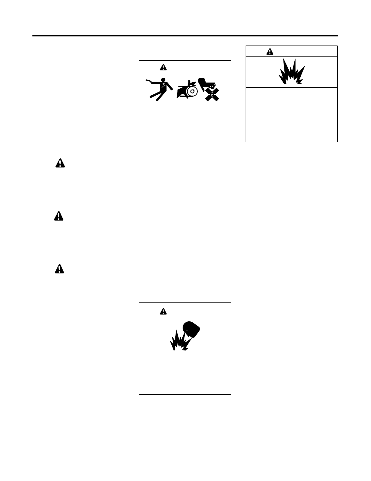
Accidental Starting
WARNING
Accidental starting.
Can cause severe injury or death.
Disconnect the battery cables before
working on the generator set.
Remove the negative (--) lead first
when disconnecting the battery.
Reconnect the negative (--) lead last
when reconnecting the battery.
Disabling the generator set.
Accidental starting can cause
severe injury or death. Before
working on the generator set or
equipment connected to the set,
disable the generator set as follows:
(1) Press the generator set off/reset
button to shut down the generator set.
(2) Disconnect the power to the battery
charger, if equipped. (3) Remove the
battery cables, negative (--) lead first.
Reconnect the negative (--) lead last
when reconnecting the battery. Follow
these precautions to prevent the
starting of the generator set by the
remote start/stop switch.
Battery
WARNING
Sulfuric acid in batteries.
Can cause severe injury or death.
Wear protective goggles and
clothing. Battery acid may cause
blindness and burn skin.
WARNING
Explosion.
Can cause severe injury or death.
Relays in the battery charger
cause arcs or sparks.
Locate the battery in a well-ventilated
area. Isolate the battery charger from
explosive fumes.
Battery electrolyte is a diluted
sulfuric acid. Battery acid can cause
severe injury or death. Battery acid
can cause blindness and burn skin.
Always wear splashproof safety
goggles, rubber gloves, and boots
when servicing the battery. Do not
open a sealed battery or mutilate the
battery case. If battery acid splashes in
the eyes or on the skin, immediately
flush the affected area for 15 minutes
with large quantities of clean water.
Seek immediate medical aid in the case
of eye contact. Never add acid to a
battery after placing the battery in
service, as this may result in hazardous
spattering of battery acid.
Battery acid cleanup. Battery acid
can cause severe injury or death.
Battery acid is electrically conductive
and corrosive. Add 500 g (1 lb.) of
bicarbonate of soda (baking soda) to a
container with 4 L (1 gal.) of water and
mix the neutralizing solution. Pour the
neutralizing solution on the spilled
battery acid and continue to add the
neutralizing solution to the spilled
battery acid until all evidence of a
chemical reaction (foaming) has
ceased. Flush the resulting liquid with
water and dry the area.
TP-6803 1/15 5Safety Precautions and Instructions
Battery gases. Explosion can cause
severe injury or death. Battery gases
can cause an explosion. Do not smoke
or permit flames or sparks to occur near
a battery at any time, particularly when
it is charging. Do not dispose of a
battery in a fire. To prevent burns and
sparks that could cause an explosion,
avoid touching the battery terminals
with tools or other metal objects.
Remove all jewelry before servicing the
equipment. Discharge static electricity
from your body before touching
batteries by first touching a grounded
metal surface away from the battery. To
avoid sparks, do not disturb the battery
charger connections while the battery
is charging. Always turn the battery
charger off before disconnecting the
battery connections. Ventilate the
compartments containing batteries to
prevent accumulation of explosive
gases.
Battery short circuits. Explosion
can cause severe injury or death.
Short circuits can cause bodily injury
and/or equipment damage.
Disconnect the battery before
generator set installation or
maintenance. Remove all jewelry
before servicing the equipment. Use
tools with insulated handles. Remove
the negative (--) lead first when
disconnecting the battery. Reconnect
the negative (--) lead last when
reconnecting the battery. Never
connect the negative (--) battery cable
to the positive (+) connection terminal
of the starter solenoid. Do not test the
battery condition by shorting the
terminals together.
Engine Backfire/Flash
Fire
WARNING
Fire.
Can cause severe injury or death.
Servicing the air cleaner. A sudden
backfire can cause severe injury or
death. Do not operate the generator
set with the air cleaner removed.
Servicing the fuel system. A flash
fire can cause severe injury ordeath.
Do not smoke or permit flames or
sparks near the carburetor, fuel line,
fuel filter, fuel pump, or other potential
sources of spilled fuels or fuel vapors.
Catch fuels in an approved container
when removing the fuel line or
carburetor.
Combustible materials. A fire can
cause severe injury or death.
Generator set engine fuels and fuel
vapors are flammable and explosive.
Handle these materials carefully to
minimize the risk of fire or explosion.
Equip the compartment or nearby area
with a fully charged fire extinguisher.
Select a fire extinguisher rated ABC or
BC for electrical fires or as
recommended by the local fire code or
an authorized agency. Train all
personnel on fire extinguisher
operation and fire prevention
procedures.
Exhaust System
WARNING
Carbon monoxide.
Can cause severe nausea,
fainting, or death.
The exhaust system must be
leakproof and routinely inspected.
Generator set operation. Carbon
monoxide can cause severe nausea,
fainting, or death. Carbon monoxide
is an odorless, colorless, tasteless,
nonirritating gas that can cause death if
inhaled for even a short time. Avoid
breathing exhaust fumes when working
on or near the generator set. Never
operate the generator set inside a
building. Never operate the generator
set where exhaust gas could seep
inside or be drawn into a potentially
occupied building through windows, air
intake vents, or other openings.
Carbon monoxide detectors.
Carbon monoxide can cause severe
nausea, fainting, or death. Install
carbon monoxide detectors on each
level of any building adjacent to the
generator set. Locate the detectors to
adequately warn the building’s
occupants of the presence of carbon
monoxide. Keep the detectors
operational at all times. Periodically
test and replace the carbon monoxide
detectors according to the
manufacturer’s instructions.
Carbon monoxide symptoms.
Carbon monoxide can cause severe
nausea, fainting, or death. Carbon
monoxide is a poisonous gas present in
exhaust gases. Carbon monoxide is an
odorless, colorless, tasteless,
nonirritating gas that can cause death if
inhaled for even a short time. Carbon
monoxide poisoning symptoms include
but are not limited to the following:
D Light-headedness, dizziness
D Physical fatigue, weakness in
joints and muscles
D Sleepiness, mental fatigue,
inability to concentrate
or speak clearly, blurred vision
D Stomachache, vomiting, nausea
If experiencing any of these symptoms
and carbon monoxide poisoning is
possible, seek fresh air immediately
and remain active. Do not sit, lie down,
or fall asleep. Alert others to the
possibility of carbon monoxide
poisoning. Seek medical attention if
the condition of affected persons does
not improve within minutes of breathing
fresh air.
Do not smoke or permit flames or
sparks near fuels or the fuel system.
TP-6803 1/156 Safety Precautions and Instructions
Fuel System
WARNING
Natural Gas—Adequate ventilation is
mandatory. Because natural gas rises,
install natural gas detectors high in a
room. Inspect the detectors per the
manufacturer’s instructions.
WARNING
Explosive fuel vapors.
Can cause severe injury or death.
Use extreme care when handling,
storing, and using fuels.
The fuel system. Explosive fuel
vapors can cause severe injury or
death. Vaporized fuels are highly
explosive. Use extreme care when
handling and storing fuels. Store fuels
in a well-ventilated area away from
spark-producing equipment and out of
the reach of children. Never add fuel to
the tank while the engine is running
because spilled fuel may ignite on
contact with hot parts or from sparks.
Do not smoke or permit flames or
sparks to occur near sources of spilled
fuel or fuel vapors. Keep the fuel lines
and connections tight and in good
condition. Do not replace flexible fuel
lines with rigid lines. Use flexible
sections to avoid fuel line breakage
caused by vibration. Do notoperate the
generator set in the presence of fuel
leaks, fuel accumulation, or sparks.
Repair fuel systems before resuming
generator set operation.
Gas fuel leaks. Explosive fuel
vapors can cause severe injury or
death. Fuel leakage can cause an
explosion. Check the LPG vapor or
natural gas fuel system for leakage by
using a soap and water solution with
the fuel system test pressurized to
6--8 ounces per square inch
(10--14 inches water column). Do not
use a soap solution containing either
ammonia or chlorine because both
prevent bubble formation. Asuccessful
test depends on the ability of the
solution to bubble.
Explosive fuel vapors can cause
severe injury or death. Ta ke
additional precautions when using the
following fuels:
Propane (LPG)—Adequate ventilation
is mandatory. Because propane is
heavier than air, install propane gas
detectors low in a room. Inspect the
detectors per the manufacturer’s
instructions.
Hazardous Noise
CAUTION
Hazardous noise.
Can cause hearing loss.
Never operate the generator set
without a muffler or with a faulty
exhaust system.
Engine noise. Hazardous noise can
cause hearing loss. Generator sets
not equipped with sound enclosures
can produce noise levels greater than
105 dBA. Prolonged exposure to noise
levels greater than 85 dBA can cause
permanent hearing loss. Wear hearing
protection when near an operating
generator set.
Hazardous Voltage/
Moving Parts
DANGER
Hazardous voltage.
Will cause severe injury or death.
This equipment must be installed and
serviced by qualified electrical
personnel.
WARNING
Hazardous voltage.
Can cause severe injury or death.
Operate the generator set only when
all guards and electrical enclosures
areinplace.
Moving parts.
Hazardous voltage.
Backfeed to the utility system can
cause property damage, severe
injury, or death.
If the generator set is used for
standby power, install an automatic
transfer switch to prevent inadvertent
interconnection of standby and
normal sources of supply.
CAUTION
Welding the generator set.
Can cause severe electrical
equipment damage.
Never weld components of the
generator set without first
disconnecting the battery, controller
wiring harness, and engine electronic
control module (ECM).
Grounding electrical equipment.
Hazardous voltage can cause
severe injury or death. Electrocution
is possible whenever electricity is
present. Ensure you comply with all
applicable codes and standards.
Electrically ground the generator set,
transfer switch, and related equipment
and electrical circuits. Turn off the main
circuit breakers of all power sources
before servicing the equipment. Never
contact electrical leads or appliances
when standing in water or on wet
ground because these conditions
increase the risk of electrocution.
Welding on the generator set. Can
cause severe electrical equipment
damage. Before welding on the
generator set perform the following
steps: (1) Remove the battery cables,
negative (--) lead first. (2) Disconnect
all engine electronic control module
(ECM) connectors. (3) Disconnect all
generator set controller and voltage
regulator circuit board connectors.
(4) Disconnect the engine batterycharging alternator connections.
(5) Attach the weld ground connection
close to the weld location.
TP-6803 1/15 7Safety Precautions and Instructions
Connecting the battery and the
battery charger. Hazardous voltage
can cause severe injury or death.
Reconnect the battery correctly,
positive to positive and negative to
negative, to avoid electrical shock and
damage to the battery charger and
battery(ies). Have a qualified
electrician install the battery(ies).
Short circuits. Hazardous
voltage/current can cause severe
injury or death. Short circuits can
cause bodily injury and/or equipment
damage. Do not contact electrical
connections with tools or jewelry while
making adjustments or repairs.
Remove all jewelry before servicing the
equipment.
Electrical backfeed to the utility.
Hazardous backfeed voltage can
cause severe injury or death. Install
a transfer switch in standby power
installations to prevent the connection
of standby and other sources of power.
Electrical backfeed into a utility
electrical system can cause severe
injury or death to utility personnel
working on power lines.
Hot Parts
WARNING
Hot engine and exhaust system.
Can cause severe injury or death.
Do not work on the generator set until
it cools.
Servicing the exhaust system. Hot
parts can cause severe injury or
death. Do not touch hot engine parts.
The engine and exhaust system
components become extremely hot
during operation.
Servicing the engine heater. Hot
parts can cause minor personal
injury or property damage. Install the
heater before connecting it to power.
Operating the heater before installation
can cause burns and component
damage. Disconnect power to the
heater and allow it to cool before
servicing the heater or nearby parts.
Notice
NOTICE
Canadian installations only.For
standby service connect the output of
the generator set to a suitably rated
transfer switch in accordance with
Canadian Electrical Code, Part 1.
Heavy Equipment
WARNING
Unbalanced weight.
Improper lifting can cause severe
injury or death and equipment
damage.
Do not use lifting eyes.
Lift the generator set using lifting bars
inserted through the lifting holes on
the skid.
TP-6803 1/158 Safety Precautions and Instructions
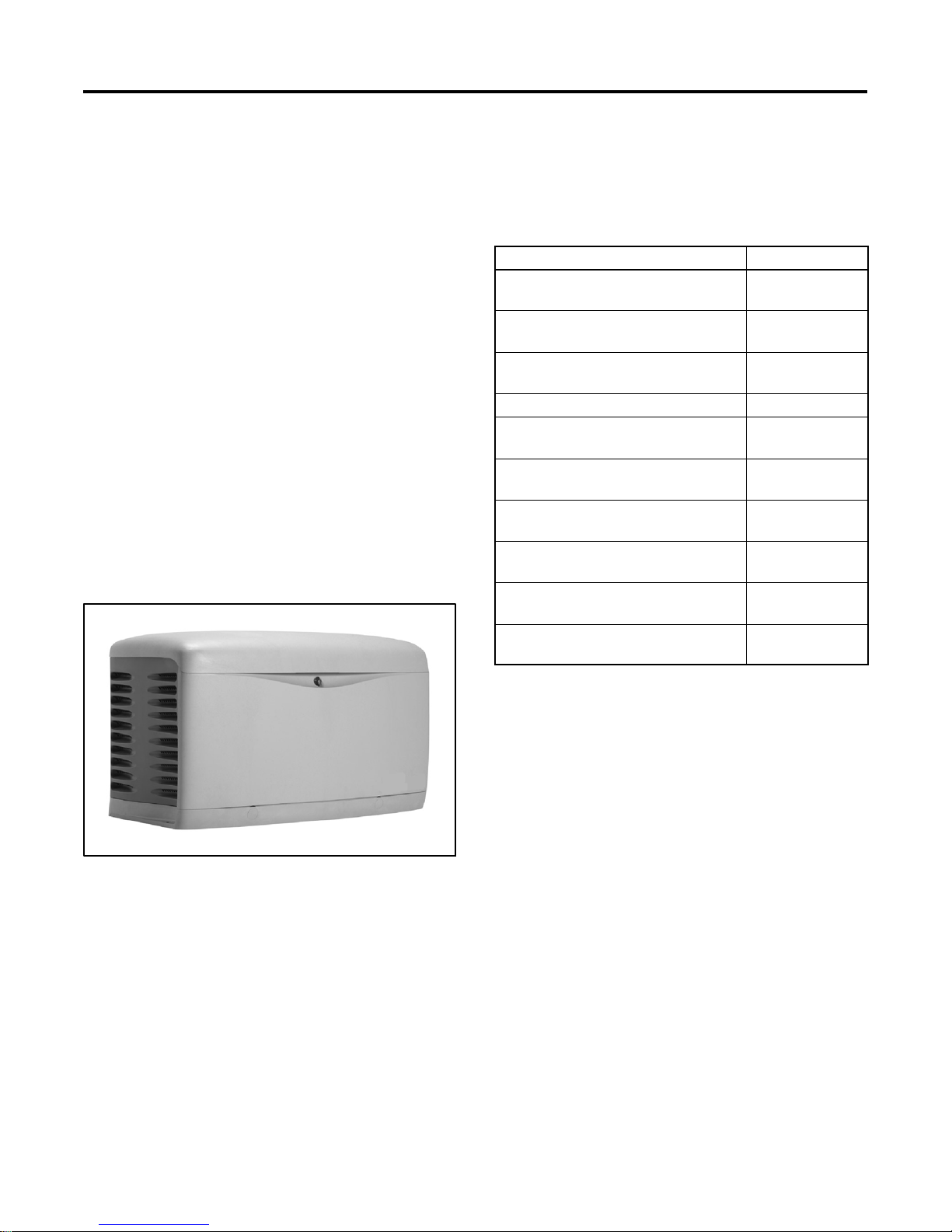
Introduction
This manual provides installation instructions for
Residential/Commercial Model generator sets. See
Figure 1. Refer to TP-6804, Operation Manual, for
generator set operation and maintenance instructions.
The generator set is approved for use in stationary
applications in locations served by a reliable utility
power source.
Have a Kohlerr authorized distributor/dealer install the
generator set outdoors according to the instructions in
this manual. The generator set installation must comply
with the National Electrical Code (NEC) and local code
requirements. Do not install this generator set indoors.
Information in this publication represents data available
at the time of print. Kohler Co. reserves the right to
change this publication and the products represented
without notice and without any obligation or liability
whatsoever.
Read this manual and carefully follow all procedures
and safety precautions to ensure proper equipment
operation and to avoid bodily injury. Read and followthe
Safety Precautions and Instructions section at the
beginning of this manual.
List of Related Literature
Figure 2 identifies related literature available for the
generator sets covered in this manual. Only trained and
qualified personnel should install or service the
generator set.
Literature Type Part Number
Operation Manual,
14/20RESA/RESALGenerator Set
Operation/Installation Manual, Model
RXT Automatic Transfer Switch
Service Manual,
14/20RESA/RESAL Generator Set
Operation Manual, OnCue Plus TP-6928
Operation/Installation Manual,
Model RDT Transfer Switch
Installation Manual,
Model RSB Transfer Switch
Operation Manual,
Model RSB Transfer Switch
Installation Instructions,
Load Control Module (LCM)
Installation Instructions,
Programmable Interface Module (PIM)
Installation Instructions,
Concrete Mounting Pads
Figure 2 Related Literature
TP-6804
TP-6807
TP-6735
TP-6345
TP-6486
TP-6487
TT-1574
TT-1584
TT--1619
Startup and Registration
When the generator set is installed, complete the
startup and installation checklists supplied with the
startup notification form. Complete and sign the startup
notification form and register the unit using the Kohler
zaa28533
Figure 1 14/20RESA/RESAL Generator Set
TP-6803 1/15 9
online Warranty Processing System.

Service Assistance
For professional advice on generator set power
requirements andconscientious service, pleasecontact
your nearest Kohler distributor or dealer.
D Consult the Yellow Pages under the heading
Generators—Electric.
D Visit the Kohler Power Systems website at
KOHLERPower.com.
D Look at thelabels and stickers onyour Kohler product
or review the appropriate literature or documents
included with the product.
D Call toll free in the US and Canada 1-800-544-2444.
D Outside the US and Canada, call the nearest regional
office.
Headquarters Europe, Middle East, Africa
(EMEA)
Kohler Power Systems Netherlands B.V.
Kristallaan 1
4761 ZC Zevenbergen
The Netherlands
Phone: (31) 168 331630
Fax: (31) 168 331631
Asia Pacific
Power Systems Asia Pacific Regional Office
Singapore, Republic of Singapore
Phone: (65) 6264-6422
Fax: (65) 6264-6455
China
North China Regional Office, Beijing
Phone: (86) 10 6518 7950
(86) 10 6518 7951
(86) 10 6518 7952
Fax: (86) 10 6518 7955
East China Regional Office, Shanghai
Phone: (86) 21 6288 0500
Fax: (86) 21 6288 0550
India, Bangladesh, Sri Lanka
India Regional Office
Bangalore, India
Phone: (91) 80 3366208
(91) 80 3366231
Fax: (91) 80 3315972
Japan, Korea
North Asia Regional Office
Tokyo, Japan
Phone: (813) 3440-4515
Fax: (813) 3440-2727
Latin America
Latin America Regional Office
Lakeland, Florida, USA
Phone: (863) 619-7568
Fax: (863) 701-7131
TP-6803 1/1510

Section 1 Installation
1.1 Introduction
DANGER
Hazardous voltage.
Will cause severe injury or death.
This equipment must be installed and
serviced by qualified electrical
personnel.
WARNING
Carbon monoxide.
Can cause severe nausea,
fainting, or death.
The exhaust system must be
leakproof and routinely inspected.
Generator set operation. Carbon monoxide can cause
severe nausea, fainting, or death. Carbon monoxide is an
odorless, colorless, tasteless, nonirritating gas that can cause
death if inhaled for even a short time. Avoid breathing exhaust
fumes when working on or near the generator set. Never
operate the generator set inside a building. Never operate the
generator set where exhaust gas could seep inside or be
drawn into a potentially occupied buildingthrough windows, air
intake vents, or other openings.
The generator set must be installed outdoors. The
exhaust systems on enclosed units are designed for
outdoor installation only.
Note: DO NOT install these generator sets inside a
building.
Note: Install carbon monoxide (CO) detector(s) on
each level of any building adjacent to a generator
set. Locate the detectors to adequately warn the
building’s occupants of the presence of carbon
monoxide.
Obtain a building permit and contact your local utility
companies to mark the locations of underground pipes
and cables.
Read and follow the safety precautions in this manual
and observe the decals on the equipment. Refer to the
diagrams and drawings in this manual for dimensions
and electrical connections during the installation
procedure. Read the entire installation procedure and
obtain the accessories and tools needed before
beginning installation. Perform the steps in the order
shown.
To install optional accessories, follow the instructions
provided with each kit.
1.2 Lifting
WARNING
Carbon monoxide detectors. Carbon monoxide can
cause severe nausea, fainting, or death. Install carbon
monoxide detectors on each level of any building adjacent to
the generator set. Locate the detectors to adequately warn the
building’s occupants of the presence of carbon monoxide.
Keep the detectors operational at all times. Periodically test
and replace the carbon monoxide detectors according to the
manufacturer’s instructions.
Have thegenerator set installed by an authorized Kohler
distributor/dealer or authorized representative. For all
locations, ensure that the installation complies with
applicable national and local codes. In the United
States, the installation must comply with the National
Electrical Code (NEC) and local codes. For Canadian
installations, refer to the Canadian Electrical Code
(CEC).
TP-6803 1/15 11Section 1 Installation
Unbalanced weight.
Improper lifting can cause severe
injury or death and equipment
damage.
Do not use lifting eyes.
Lift the generator set using lifting bars
inserted through the lifting holes on
the skid.
Model Weight, kg (lb.)
14RESA/RESAL
20RESA/RESAL
191 (420)
243 (535)
Figure 1-1 Approximate Weights
Approximate generator set weights are shown in
Figure 1-1. Uselifting bars inserted through the holes in
the skid to lift the unit. See the dimension drawings in
Section 2 for lifting hole locations.
1.3 Generator Set Inspection
Complete a thorough inspection of the generator set.
Check for the following:
1. Inspect the generator set for loose or damaged
parts or wires. Repair or tighten any loose parts
before installation.
2. Check the engine oil. Fill, if necessary, with the
recommended viscosity and grade of oil. Use
synthetic oil, API (American Petroleum Institute)
Service Class SG or higher. See TP-6804,
Operation Manual, for additional information.
1.4 Location and Mounting
Install the generator set outdoors near the incoming gas
service. The generator set location must allow easy
access for maintenance and service. The
recommended distance from a structure is dependent
on state and local codes. See the dimension drawing in
Section 2 for the recommended clearance from
structures and non-combustible materials.
Locate the generator set so that the hot exhaust does
not blow on plants or other combustible materials. No
plants, shrubs, or other combustible materials are
allowed within 1.2 m (4 ft.) of the exhaust end of the
generator set.
Do not installthe generator set where exhaust gas could
accumulate and seep inside or be drawn into a
potentially occupied building. Furnace and other similar
intakes must be at least 3 m (10 ft.) from the exhaust
end of the generator set.
Notice
DO NOT locate the generator set near patios,
decks, play areas, o r animal shelters. Keep items
such as lawn furniture, toys, sports equipment,
and all combustible materials away from the
generator set exhaust outlet.
Remind family members, children, and visitors to
use caution near the generator set. Generator
sets connected to automatic transfer switches
start automatically during exercise periods and
power outages. Some generator set components
become hot when the generator set is running and
remain hot for a time after the generator set shuts
down.
1.4.1 Mounting Area
The generator set is shipped on an engineered
composite mounting pad. Prepare a flat, level mounting
area covered with a weed barrier and gravel or a
concrete mounting pad. Set the composite mounting
pad directly on the gravel or concrete.
Do not install the composite mounting pad directly on
grass, wood, or other combustible materials. Clear all
combustible materials, including plants and shrubs,
building materials, and lawn furniture, from an area at
least 1.2 m (4 ft.) beyond the exhaust end of the
generator set. See the dimension drawing in Section 2.
1.4.2 Concrete Mounting Pads
Kohler Co. offers optional concrete mounting pads that
are custom-designed for Model 14RESA/RESAL and
20RESA/RESAL generator sets. Three-inch and
four-inch thick pads are available. Four-inch pads are
recommended for storm-prone areas. See TT-1619 for
instructions to install the mounting pad, if necessary.
1.4.3 Exhaust Requirements
WARNING
Hot engine and exhaust system.
Can cause severe injury or death.
Do not work on the generator set until
it cools.
TP-6803 1/1512 Section 1 Installation

Figure 1-2 gives the exhaust temperature at rated load.
The engine exhaust mixes with the generator set
cooling air at the exhaust end of the enclosure. Mount
the generator set so that the hot exhaust does not blow
on plants or other combustible materials. Maintain the
clearances shown in the dimension drawing in
Section 2.
Temperature,
Exhaust
Exhaust gas exiting the enclosure
at rated kW, _C(_F)
_C(_F)
260 (500)
Figure 1-2 Exhaust Flow and Temperature
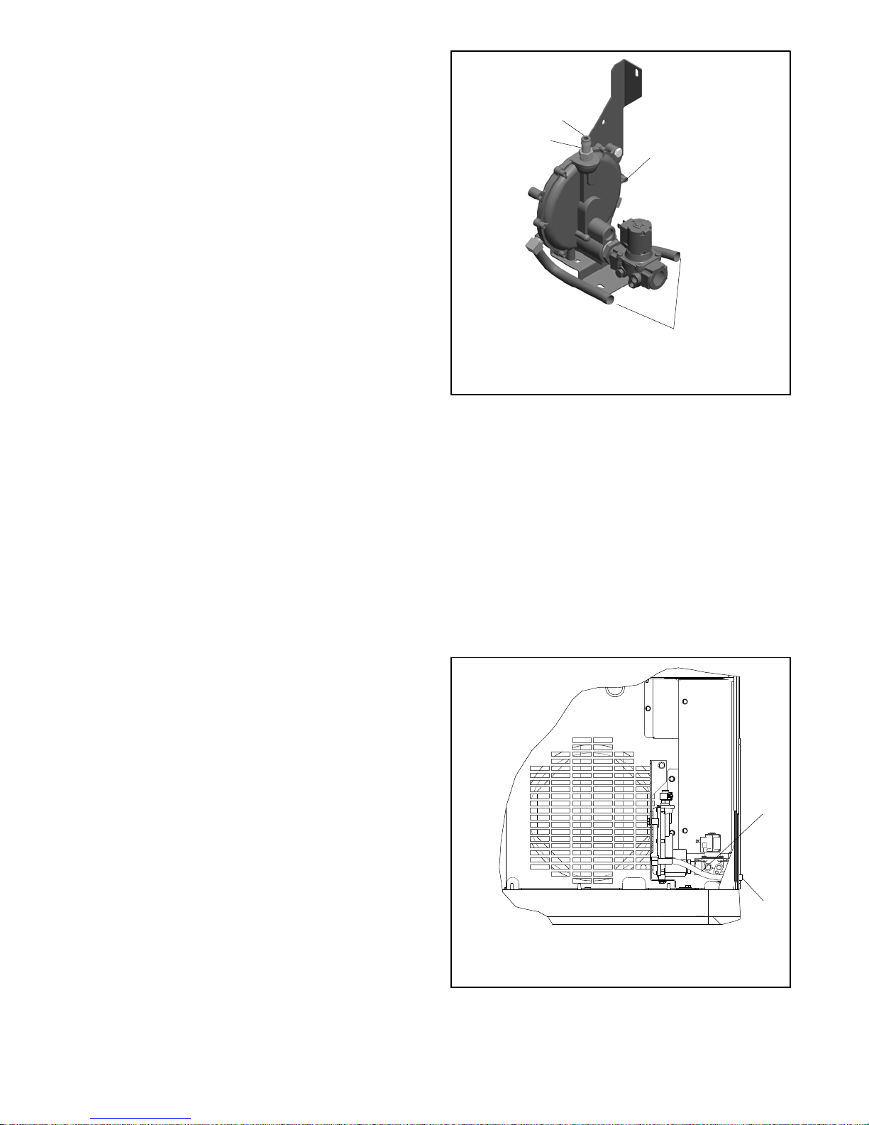
1.6 Access the Air Intake Area
The battery, fuel system, and electrical connections are
located in theair intake area. Raise the roof and remove
the enclosure panel to access the air intake area during
installation as described below.
1. Remove two screws from the top of the air intake
panel. Pull the the panel up and off. See
Figure 1-4.
2. To make the electrical connections, you will also
need to remove the cover panel over the terminal
block as shown in Section 1.9.3.
The generator set requires correct air flow for cooling
and combustion. The inlet and outlet openings in the
sound enclosure provide the cooling and combustion
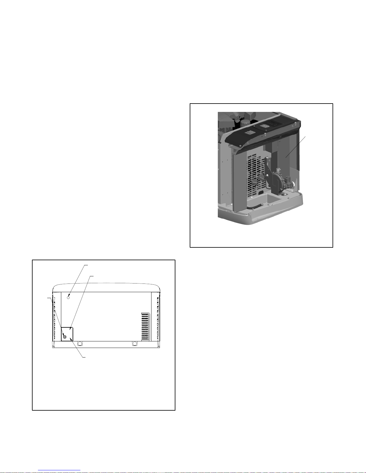
air. Figure 1-3 shows the locations of the cooling air
intake and exhaust vents. Inspect the air inlet and outlet
openings inside and outside the enclosure to ensure
that the air flow is not blocked.
1
REAR VIEW
1. Air intake
2. Exhaust outlet
1
2
tp6733
Figure 1-3 Cooling Air Intake and Exhaust
The generator set is designed to operate with all
enclosure panels and internal baffling in place. If during
installation, maintenance or repair the unit must be
operated without the complete enclosure and baffling as
shipped from the factory make sure the exhaust panel is
removed as well.
3. Reinstall the panels after all electrical connections
are complete and the battery is installed and
connected.
1. Remove 2 screws.
ADV-8424
Figure 1-4 Removing the Air Intake Panel
1
1.5 Dimension Drawings
See the dimension drawings in Section 2 for the
generator set dimensions, fuel and electric inlet
locations, and recommended clearance.
TP-6803 1/15 13Section 1 Installation
1.7 Fuel Requirements
1.7.1 Fuel Supply
The generator set operates using natural gas or LPG
fuel. The generator set is EPA-certified for both natural
gas and LPG fuels.
The fuel system installation must comply with the NEC
and local codes.
WARNING
Explosive fuel vapors.
Can cause severe injury or death.
Use extreme care when handling,
storing, and using fuels.
Explosive fuel vapors can cause severe injury or death.
Take additional precautions when using the following fuels:
Propane (LPG)—Adequate ventilation is mandatory.
Because propane is heavier than air, install propane gas
detectors low in a room. Inspect the detectors per the
manufacturer’s instructions.
Natural Gas—Adequate ventilation is mandatory. Because
natural gas rises, install natural gas detectors high in a room.
Inspect the detectors per the manufacturer’s instructions.
Because of variable climates and geographical
considerations, contact the local fuel supplier for fuel
system planning and installation. Figure 1-5 lists the
recommended fuel ratings and other fuel supply
information for natural gas and LPG fuels.
Verify that the output pressure from the primary gas
utility pressure regulator is within the range shown in
Figure 1-5 and that the utility gas meter flow rate is
sufficient to supply the generator set at rated load plus
all other gas-consuming appliances. For LPG tanks,
verify that the output pressure is as shown in Figure 1-5.
See Figure 1-6 for fuel consumption. Contact the fuel
supplier for flow rate information or a gas meter
upgrade, if necessary.
Natural
3
Gas
1.3--2.7
(5--11)
LPG
1.7--2.7
(7--11)
Fuel type
Fuel supply inlet 1/2 NPT
Fuel supply pressure,
kPa (in. H
O)
2
Fuel flow rate, maximum, Btu/hr.:
14RESA/RESAL 193,000 203,000
20RESA/RESAL 281,000 340,000
Nominal Fuel Rating, Btu/ft.
Natural gas 1000
LPG 2500
Fuel Type % Load
100% 5.4 (193) 4.9 (175) 8.0 (281) 6.4 (225)
Natural Gas
LPG
LPG conversion factors:
8.58 ft.
0.535 m
36.39 ft.
3
=1lb.
3
3
=1kg
= 1 gal.
75% 4.7 (163) 4.2 (148) 6.9 (243) 5.4 (189)
50% 3.5 (124) 3.1 (108) 4.6 (161) 3.9 (139)
25% 2.6 (93) 2.4 (84) 3.6 (127) 2.9 (103)
100% 2.3 (81) 2.1 (74) 3.9 (136) 2.9 (102)
75% 2.1 (75) 1.9 (68) 3.1 (109) 2.4 (85)
50% 1.8 (60) 1.5 (53) 2.3 (82) 1.8 (63)
25% 1.2 (45) 1.1 (40) 1.7 (59) 1.3 (47)
Figure 1-6 Fuel Consumption
Figure 1-5 Fuel Supply
Fuel Consumption, m3/hr. (cfh)
14RESA/RESAL 20RESA/RESAL
60 Hz 50 Hz 60 Hz 50 Hz
Nominal fuel rating:
Natural gas: 37 MJ/m
LPG: 93 MJ/m
3
(1000 Btu/ft.3)
3
(2500 Btu/ft.3)
TP-6803 1/1514 Section 1 Installation

1.7.2 Fuel Pipe Size
Ensure that the fuel pipe size and length meet the
specifications in Figure 1-7. Measure the pipe length
from the primary gas pressure regulator to the pipe
connection on the generator set fuel inlet. Add 2.4 m
(8 ft.) to the measured length for each 90 degree elbow.
Compare the total pipe length with the chart in
Figure 1-7 to find the required pipe size.
Contact local LPG provider for LPG installation
information.
Minimum Gas Pipe Size Recommendation, in. NPT
14RESA/RESAL 20RESA/RESAL
Pipe
Length,
m (ft.)
8 (25) 3/4 3/4 1 3/4
15 (50) 1 3/4 1 1
30 (100) 1 1 11/4 1
46 (150) 11/4 1 11/4 11/4
61 (200) 11/4 1 11/4 11/4
Natural
Gas
(193,000
Btu/hr.)
LPG
(203,000
Btu/hr.)
Figure 1-7 Fuel Pipe Size Recommendations
Natural
Gas
(281,000
Btu/hr.)
LPG
(340,000
Btu/hr.)
Apply pipe sealant thatis approved for fuel connections.
Hold the fuel solenoid valve with a wrench when
tightening the fuel connections.
Note: Do not hold the fuel solenoid valve coil when
tightening the fuel connections. See Figure 1-8
for the recommended wrench locations.
1
Note: Do NOT hold the valve
coil when tightening
connections.
IMG_0351
1. Hold valve with wrench on flats of valve body
2. Alternate wrench location
2
1.7.3 Connecting the Fuel Supply
The dimension drawing in Section 2 shows the location
of the fuel inlet connection. Have the fuel supplier install
rigid gas piping and a manual fuel shut-off valve. The
fuel supply line should line up with the generator set fuel
inlet and end about 12 inches away to allow connection
with asection of flexible fuel line. Use flexible sections to
prevent fuel line breakage caused by vibration.
Note: Do not bend the flexible fuel line to make up for
misalignment of the fuel supply line and the
generator set fuel inlet.
Figure 1-8 Holding Fuel Valve to Tighten Fuel
Connections
Open the manual fuel valves and test all fuel
connections using soapy water. If a leak is found, close
the fuel valves, clean the fittings, and apply fresh
sealant. Check for fuel leaks again with the generator
set running.
Protect all fuel lines from machinery or equipment
contact, adverse weather conditions, and environmental
damage.
TP-6803 1/15 15Section 1 Installation
1.8 Fuel Conversion
The multi-fuel system allows conversion from natural
gas to LPG (or vice-versa) in the field while maintaining
emissions-standard compliance. A trained technician
or an authorized distributor/dealer can convert the fuel
system.
After converting the fuel system, change the Fuel Type
setting on the controller. See the Operation Manual for
instructions to change settings at the controller, or use a
personal (laptop) computer and Kohlerr SiteTecht
software to change the setting.
Rating Change
Converting the fuel will change the generator set rating.
See the generator set specification sheet for ratings with
natural gas and LP. Order a new nameplate with the
updated rating and fuel information from an authorized
distributor/dealer, if necessary. Provide the following
information from the original nameplate:
WARNING
Explosive fuel vapors.
Can cause severe injury or death.
Use extreme care when handling,
storing, and using fuels.
Explosive fuel vapors can cause severe injury or death.
Take additional precautions when using the following fuels:
Propane (LPG)—Adequate ventilation is mandatory.
Because propane is heavier than air, install propane gas
detectors low in a room. Inspect the detectors per the
manufacturer’s instructions.
Natural Gas—Adequate ventilation is mandatory. Because
natural gas rises, install natural gas detectors high in a room.
Inspect the detectors per the manufacturer’s instructions.
D Model Number D kVA
D Spec Number D Amps
D Serial Number D Volts
D Fuel (original and new) D Hz
D kW
Attach the new nameplate over the old one. Do NOT
cover the UL listing information on the old nameplate.
WARNING
Accidental starting.
Can cause severe injury or death.
Disconnect the battery cables before
working on the generator set.
Remove the negative (--) lead first
when disconnecting the battery.
Reconnect the negative (--) lead last
when reconnecting the battery.
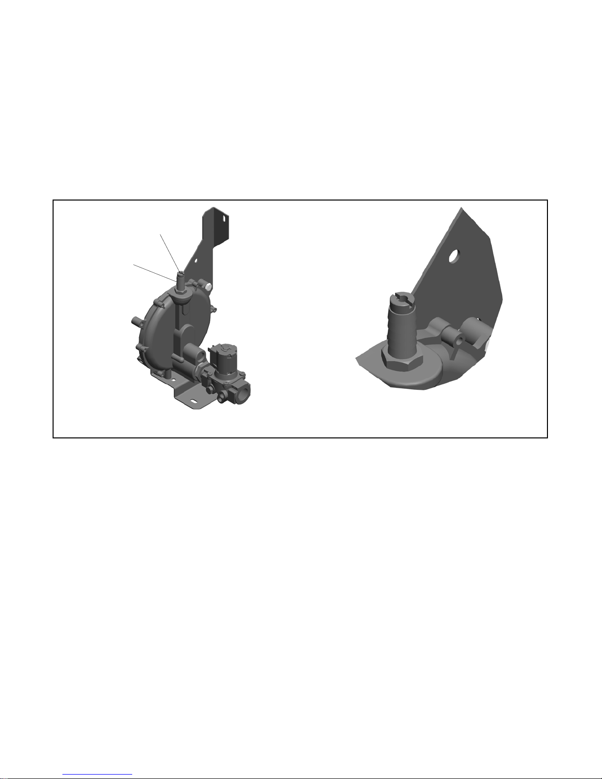
1.8.1 Fuel Conversion, 14RESA/RESAL
Equipped with Fuel Block
Note: Model 14RESA/RESAL generator sets built
before June 26, 2014 use a fuel block for the fuel
type selection. See Figure 1-9 and use the
instructions in this section for fuel conversion.
Model 14RESA/RESAL generators built June 26,
2014, or later are not equipped with the fuel block.
These units use fuel orifice fittings installed in the
hose fitting at the fuel regulator. See Section
1.8.2 for fuel conversion instructions.
Two fuel connections on the fuel block allow fieldconversion between natural gas and LPG. The fuel
metering valves are factory-set and sealed to comply
with applicable e mission standards and to provide the
best possible hot and cold starting.
Note: Do not adjust the factory-sealed fuel-metering
adjustments on the fuel block. Changing the fuelmetering adjustmentsmay violate federalor state
laws.
Disabling the generator set. Accidental starting can
cause severe injury or death. Before working on the
generator set or equipment connected to the set, disable the
generator set as follows: (1) Press the generator set off/reset
button to shut down the generator set. (2) Disconnect the
power to the battery charger, if equipped. (3) Remove the
battery cables, negative (--) lead first. Reconnect the negative
(--) lead last when reconnecting the battery. Follow these
precautions to prevent the starting of the generator set by the
remote start/stop switch.
Use the following procedure to convert from natural gas
(NG) to LPG. See Figure 1-9 for the fuel system
component locations.
TP-6803 1/1516 Section 1 Installation
Procedure to convert from NG to LPG,
14RESA/RESAL with fuel block
1. Press the OFF button on the generator set
controller.
2. Disconnect the power to the battery charger.
3. Disconnect the generator set engine starting
battery, negative (--) lead first.
4. Turn off the fuel supply.
Conversion from LPG to Natural Gas
To convert from LPG to natural gas, follow the fuel
conversion procedure above, moving the hose fitting to
the natural gas port and plugging the LP port. Connect
the DSAI leads for natural gas. See Figure 1-9.
1
10
2
LPG setup
shown
5. Remove the hose clamp and fuel hose from the
hose fitting in the fuel block. See F igure 1-9.
6. Remove the hose fitting from the natural gas outlet
port in the fuel block. See Figure 1-9.
7. Remove the plug from the LP port in the fuel block.
SeeFigure1-9.
8. Clean the plug with a dry cloth or brush, apply fresh
pipe sealant, and install the plug into the natural
gas outlet port.
9. Clean the hose fitting with a dry cloth or brush,
apply fresh pipe sealant to the threads, and install
the fitting into the LP port.
Note: Do not adjust the fuel metering valves.
10. Slide the hose onto the hose fitting and secure it
with the clamp.
11. Disconnect digital spark-advance ignition (DSAI)
leads 65 and N3 for LPG. The DSAI leads are
located near the fuel solenoid valve. See
Figure 1-9.
9
8
7
6
3
4
photo223
5
12. Connect and turn on the new fuel supply.
DSAI Lead Connection
13. Reconnect the generator set engine starting
battery leads, negative (--) lead last.
14. Reconnect power to the battery charger.
15. Start the generator set by pressing the RUN button
on the generator set controller.
16. Check for leaks using a gas leak detector.
17. Run the generator set and check the operation.
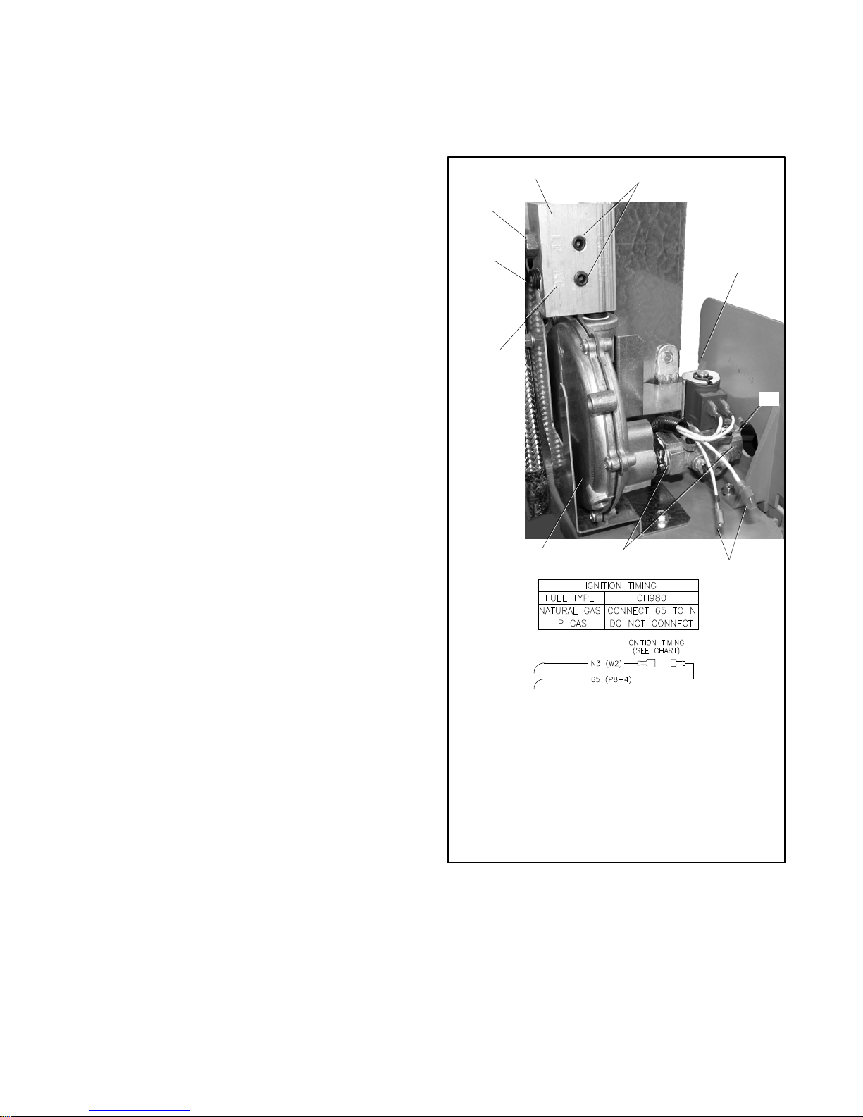
1. Fuel block (14RES only)
2. Fuel metering valves—factory -sealed, do not adjust
3. Fuel solenoid valve coil
4. Fuel inlet, 1/2 in. NPT
5. DSAI leads 65 and N3
6. Recommended holding points for tightening fuel connection
7. Fuel regulator
8. Ports are labeled LP and NG
9. Plug
10. Hose fitting
Figure 1-9 Fuel System, 14RESA/RESAL Equipped
with Fuel Block (built before June 26,
18. Press the OFF button to to shut down the generator
2014)
set.
TP-6803 1/15 17Section 1 Installation

1.8.2 Fuel Conversion, 14RESA/RESAL
Equipped with Fuel Orifice
Fittings
Note: Model 14RESA/RESAL generator sets built
before June 26, 2014, use a fuel block for the fuel
type selection. See Figure 1-9 and use the
instructions Section 1.8.1 for fuel conversion.
Model 14RESA/RESALgenerators built June 26,
2014, or later are not equipped with the fuel block.
These units use fuel orifice fittings installed in the
hose fitting at the fuel regulator. See Figure 1-11
and use the instructions in this section for fuel
conversion.
For natural gas and LPG fuel, orifice fittings are used in
the fuel line. See Figure 1-10. The natural gas orifice
fitting is silver in color and stamped NG. The LPG fitting
is gold in color and stamped LPG. The fittings are
threaded. A straight-blade screwdriver is required to
remove and replace the fittings.
1
2
NG LPG
Figure 1-10 NG and LPG Fuel Orifice Fittings
The unit is typically shipped set up for natural gas, with
the LPG fitting tied near the fuel solenoid valve. To
convert to LPG, remove the NG fitting and install the
LPG fitting as described below. See Figure 1-11 for the
fuel system component locations.
Procedure to Convert from NG to LPG,
14RESA/RESAL with fuel orifice fittings
1. Press the OFF button on the generator set
controller.
2. Disconnect the utility power to the generator.
3. Disconnect the generator set engine starting
battery, negative (--) lead first.
4. Turn off and disconnect the fuel supply.
5. Remove the hose clamp and fuel hose from the
hose fitting. See Figure 1-11.
3
DSAI Lead Connection
1. LPG fitting tied to bracket for shipping
2. Fuel hose and clamp
3. DSAI Leads
Figure 1-11 Fuel System, As Shipped (Model
14RESA/RESAL built after June 26,
2014)
6. Use a straight-blade screwdriver to remove the NG
orifice from the hose fitting. See Figure 1-12.
7. Insert the LPG orifice into the hose fitting. Use a
straight-blade screwdriver to tighten the fitting until
it is snug.
8. Slide the hose onto the hose fitting and secure it
with the clamp.
9. Disconnect digital spark-advance ignition (DSAI)
leads 65 and N3 for LPG. The DSAI leads are
TP-6803 1/1518 Section 1 Installation
located near the fuel solenoid valve. See
Figure 1-11.
10. Connect and turn on the new fuel supply.
15. Run the generator set and check the operation.
16. Press the OFF button to shut down the generator
set.
11. Reconnect the generator set engine starting
battery leads, negative (--) lead last.
12. Reconnect the utility power to the generator.
13. Start the generator set by pressing the RUN button
on the generator set controller.
14. Check for leaks using a gas leak detector.
1
2
Conversion from LPG to Natural Gas
To convert from LPG to natural gas, repeat the steps
above, removing the LPG fuel orifice and installing the
NG fitting. Connect DSAI leads 65 and N3 together for
natural gas.
ORIFICE FITTING DETAIL
1. Orifice fitting (see detail)
2. Hose barb fitting
Figure 1-12 14RESA/RESAL Fuel System Showing Orifice Fittings (generators built after June 26, 2014)
GM84143
TP-6803 1/15 19Section 1 Installation
1.8.3 Fuel Conversion, 20RESA/RESAL
For LPG fuel, an orifice is used in the fuel line. The unit is
typically shipped set up for natural gas, with the loose
orifice tied near the fuel solenoid valve. To convert to
LPG, install the LPG orifice as described below. See
Figure 1-13 for the fuel system component locations.
Note: The generator set harness may contain a pair of
DSAI leads near the fuel solenoid valve.
Connecting or disconnecting these leads has no
effect on the 20RESA/RESAL operation.
Procedure to Convert from NG to LPG,
20RESA/RESAL
LPG setup
shown
1
2
3
1. Press the OFF button on the generator set
controller.
2. Disconnect the power to the battery charger.
3. Disconnect the generator set engine starting
battery, negative (--) lead first.
4. Turn off the fuel supply.
5. Remove the hose clamp and fuel hose from the
hose fitting. See Figure 1-13.
6. Insert the LPG orifice into the hose fitting. See
Figure 1-13.
7. Slide the hose onto the hose fitting and secure it
with the clamp.
8. Connect and turn on the new fuel supply.
9. Reconnect the generator set engine starting
battery leads, negative (--) lead last.
10. Reconnect power to the battery charger.
1. LPG orifice
2. Hose fitting
3. Regulator
4. Regulator vent tubes (vent to the outside of the controller)
4
GM84143
Figure 1-13 Fuel Regulator and LPG Orifice,
20RESA/RESAL
1.8.4 Regulator Vent Hose
Model 20RESA/RESAL generators are equipped with
fuel regulator vent hoses. Drill or punch two holes in the
enclosure at the locations shown on the template in
Appendix B. It may be convenient to cut openings forthe
electrical leads at the same time as shown on the
template and in Section 1.9.2.
Insert the open ends of the hoses through the holes to
the outside of the enclosure as shown in Figure 1-14.
11. Start the generator set by pressing the RUN button
on the generator set controller.
12. Check for leaks using a gas leak detector.
13. Run the generator set and check the operation.
14. Press the OFF button to shut down the generator
set.
Conversion from LPG to Natural Gas
To convert from LPG to natural gas, repeat the steps
above to remove the LPG fuel orifice.
1
2
sb722
1. Fuel regulator vent tubes, qty. 2
2. Drill or punch two holes and route both hoses to the outside
of the enclosure
Figure 1-14 Fuel Regulator Vent Hoses
TP-6803 1/1520 Section 1 Installation
1.9 Electrical Connections
DANGER
Hazardous voltage.
Will cause severe injury or death.
This equipment must be installed and
serviced by qualified electrical
personnel.
Grounding electrical equipment. Hazardous voltage can
cause severe injury or death. Electrocution is possible
whenever electricity is present. Ensure you comply with all
applicable codes and standards. Electrically ground the
generator set, transfer switch, and related equipment and
electrical circuits. Turn off the main circuit breakers of all
power sources before servicing the equipment. Never contact
electrical leads or appliances when standing in water or on wet
ground because these conditions increase the risk of
electrocution.
Electrical backfeed to the utility. Hazardous backfeed
voltage can cause severe injury or death. Install a transfer
switch in standby power installations to prevent the connection
of standby and other sources of power. Electrical backfeed
into a utility electrical system can cause severe injury or death
to utility personnel working on power lines.
NOTICE
Canadian installations only. For standby service connect
the output of the generator set to a suitably rated transfer
switch in accordance with Canadian Electrical Code, Part 1.
Have an authorized distributor/dealer or a licensed
electrician make the following electrical connections.
The electrical installation must comply with the National
Electrical Coder (NEC) class 1 wire designation and all
applicable local codes. Canadian installations must
comply with the Canadian Electrical Code (CEC) and
applicable local codes.
AC circuit protection. All AC circuits must include
circuit breaker or fuse protection. The circuit breaker
must be rated for a maximum of 125% of the rated
generator set output current. The circuit breaker must
open all ungrounded connectors. The generator set is
equipped with a factory-installed circuit breaker.
For customer-supplied wiring, select the wire
temperature rating in Figure 1-15 based upon the
following criteria:
D Select row 1, 2, 3, or 4 if the circuit rating is
110 amperes or less or requires #1 AWG (42.4 mm
2
or smaller conductors.
D Select row 3 or 4 if the circuit rating is greater than
110 amperes or requires #1 AWG (42.4 mm
2
)or
larger conductors.
)
Row Temp. Ra t i n g Copper (Cu) Only Cu/Aluminum (Al) Combinations Al Only
1
60_C (140_F)
or
75_C (167_F)
2
60_C (140_F) Use No. * AWG, 60_Cwire Use 60_C wire, either No. * AWG Cu or No. *
3
75_C (167_F) Use No. *[ AWG, 75_Cwire Use 75_C wire, either No. *[ AWG Cu or No.
4
90_C (194_F) Use No. *[ AWG, 90_Cwire Use 90_C wire, either No. *[ AWG Cu or No.
* The wire size for 60_C (140_F) wire is not required to be included in the marking. If included, the wire size is based on ampacities for the
wire given in Table 310-16 of the National Electrical Coder, in ANSI/NFPA 70, and on 115% of the maximum current that the circuit carries
under rated conditions. The National Electrical Coder is a registered trademark of the National Fire Protection Association, Inc.
[ Use the larger of the following conductors: the same size conductor as that used for the temperature test or one selected using the
guidelines in the preceding footnote.
Use No. * AWG, 60_Cwireor
use No. * AWG, 75_Cwire
Use 60_C wire, either No. * AWG Cu, or No. *
AWG Al or use 75_C wire, either No. * AWG
Cu or No. * AWG Al
AWG Al
*[ AWG Al
*[ AWG Al
Use 60_Cwire,No.*AWGor
use 75_Cwire,No.*AWG
Use 60_Cwire,No.*AWG
Use 75_Cwire,No.*[ AWG
Use 90_Cwire,No.*[ AWG
Figure 1-15 Terminal Markings for Various Temperature Ratings and Conductors
The National Electrical Coder is a registered trademark of the National Fire Protection Association, Inc.
TP-6803 1/15 21Section 1 Installation
1.9.1 Grounding
1.9.3 Field-Connection Terminal Block
Ground the generator set. The grounding method
must comply with NEC a nd local codes. Connect the
grounding cable to the generator set ground terminal
GND on the field-connection terminal block.
Generator sets are shipped with the generator neutral
bonded (connected) to the generator ground in the
junction box. The requirement for having a bonded
(grounded) neutral orungrounded neutral is determined
by the type of installation. At installation, the neutral can
be grounded at the generator set or lifted from the
ground stud and isolated if the installation requires an
ungrounded neutral connection at the generator. The
generator setwill operate properlywith the neutral either
bonded to ground or isolated from ground at the
generator.
Various regulations andsite configurations including the
National Electrical Code (NEC), local codes, and the
type of transfer switch used in the application determine
the grounding of the neutral at the generator. NEC
Section 250 is one example that has a very good
explanation of the neutral grounding requirements for
generators.
The generator set is equipped with a field-connection
terminal block located in the air intake area near the
junction box. Leads have been factory-installed from
the junction box to the terminal block for easy field
wiring.
See Figure 1-17 for the terminal block location.
Remove the cover panel for access to the field
connections.
1
1.9.2 Electrical Lead Entry
Drill or punch holes in the enclosure for the electrical
conduit in the locations shown in Figure 1-16. A
full-scale dimensioned template for the hole locations is
printed in Appendix B. See page 57.
1
2
4
ADV--8424
3
Note: See Appendix B for a full-scale template
with dimensions.
1. Optional emergency stop switch location. Do not use to
route wiring.
2. Utility voltage electrical lead entry point
3. ATS signal electrical lead entry point
4. 1/2 NPT female fuel inlet
adv-8424
1. Cover panel. Remove for access to field-connection terminal
block.
Figure 1-17 Field-Connection Terminal Block
Location
Figure 1-16 Electrical Lead Entry Locations
TP-6803 1/1522 Section 1 Installation
See Figure 1-18 for terminal block details. Refer to the
terminal block decal shown in Figure 1-19 for
connections and cable sizes. Also see the wiring
diagram in Section 2.
Route AC leads through flexible conduit. Ensure that
the leads and conduit do not interfere with the operation
of the generatorset or obstruct the serviceareas. Route
low-voltage communication leads through separate
conduit.
Procedure
a. Route the network cable with other low-voltage
signal wiring (for example, the RBUS
communication leads or engine start leads to
the transfer switch), in separate conduit from
the ACload leads. If the networkcable is longer
than 100 meters (328 ft.), use a repeater or
switch.
b. Use an RJ45 inline coupler to connect the
Ethernet cable to the cable in the customer
connection box. See Figure 1-18. The inline
coupler is included with the OnCue Plus kit.
1. Drill holes for the conduit fittings. See Figure 1-16
and Appendix B for the recommended electrical
inlet locations. Feed the cables through the
openings.
2. Connect the leads from the transfer switch
emergency source lugs to the L1, L2, and L3
connections on the generator set terminal block as
applicable for single or three-phase applications.
See Figure 1-18 and Figure 1-19.
3. Connect the neutral ( L0) and ground (GRD) leads
from the ATS and the main panel to the
corresponding connection points on the terminal
block. See Section 1.9.1, Grounding.
4. Connect AC power source leads to the terminal
block connections labeled LINE, NEUTRAL and
GROUND. Connect the circuit to the load side of
the transfer switch. See Section 1.9.4 for more
information about the AC power requirement.
Note: AC power must be connected to maintain
the charge on the engine starting battery.
5. For connection of optional transfer switches, the
programmable interface module (PIM), and/or a
load control module ( LCM) or load shed kit, see
Section 1.10.1.
6. If the OnCuer Plus Generator Management
System will be used with the generator set, run
category 5E network cable from the generator set
to the customer’s router or modem.
7. When connections to the terminal block are
complete, replace the cover plate.
4
3
2
1
GM84094
Note: The number of terminals varies for 1-phase
and 3-phase models. See Figure 1-19.
1. Low voltage RBUS communication to RXT ATS, PIM, LCM
or load shed kit, and/or APM.
2. Engine start connections from transfer switches other than
theRXT,ifused.
3. Ground connection for communication cable shield
4. Ethernet cable for optional OnCue Plus connection
5. AC load connections
6. AC power connections required for battery charging and
accessories
7. Connection decal; see Figure 1-19.
Figure 1-18 Field Connection Terminal Blocks
5
6
7
Note: The OnCue Plus Wireless kit allows
connection of the generator controller to the
customer’s wireless router without running a
network cable from the generator to the
customer’s router or modem. If the OnCue
Plus Wireless is used, follow the instructions
provided with the kit to install and set up the
wireless kit and proceed to step 7.
TP-6803 1/15 23Section 1 Installation

1-Phase, 1-Pole Circuit Breaker
1-Phase, 2-Pole Circuit Breaker
1.9.4 AC Power Supply
The installer must connect AC power for the battery
charger (which is integral to the RDC2 controller) and
the optional accessories shown in Figure 1-20. The
power source must comply with state and local codes.
The power to the battery charger and accessories must
be backed upby the generator so thatpower is available
at all times.
Be sure to disconnect power at the distribution panel
before makingthe connections. Connect power leadsto
the AC power connection points labeled LINE,
NEUTRAL, and GROUND on the field-connection
terminal block. Connect the circuit to the load side of the
transfer switch so that it is backed up by the generator.
See Figure 1-18 and the wiring diagrams in Section 2 for
connection details.
Power Requirement, Max.
Equipment
Battery charger
(standard)
Carburetor heater
(optional)
Battery heater (optional)
Fuel regulator heater
(optional; available for
20RESA/RESAL only)
Figure 1-20 Power Requirements
Watts Volts at 50/60 Hz
50 100--120 VAC
50 200--250 VAC
37
37
50
50
60 100--120 VAC
100 200--250 VAC
100--120 VAC
200--250 VAC
100--120 VAC
200--250 VAC
3-Phase
Figure 1-19 Terminal Block Connection Decals
TP-6803 1/1524 Section 1 Installation
1.10 ATS and Accessory
Connections
The following sections cover electrical connections of
the automatic transferswitches and RBUS accessories,
including the programmable interface module (PIM) and
the load control module (LCM) or load shed kit.
1.10.1 Transfer Switch Connection
Communication connections for a Kohlerr
Model RXT transfer switch
One Model RXT transfer switch can be connected to the
generator set. See Figure 1-21. Use shielded,
twisted-pair communication cable to connect P10-1
through P10-4 on the transfer switch interface module to
the generatorset terminal block connections A, B, PWR,
and COM. See Section 1.10.2 for the communication
cable recommendations and maximum cable length.
Connect the ATS or remote start/stop switch. Connect
the load leads from the generator set to the Emergency
source lugs on the ATS. Route low-voltage
communication leads through separate conduit fromthe
AC power and load leads. All connections must comply
with applicable state and local codes.
Note: Do not use the Kohlerr Model RRT transfer
switch with the 14/20RESA or 14/20RESAL
generator set.
1
Generator Set
GND
A
B
PWR
COM
3
RBUS
12 VDC
A
B
PWR
COM
4
3
Note: Connections 3 and 4 on the generator set are not
used with the Model RXT transfer switch.
Engine start connection for other transfer
switches or a remote start/stop switch
Connect the engine start leads from the transfer switch
or remote start switch to terminals 3 and 4 on the
terminal block. See Figure 1-22. Route the engine start
leads through separate conduit from the AC power and
load leads.
2
Interface Board on the
Model RXT Transfer Switch
4
A
B
PWR
COM
4
RXT
Note: Generator set terminal block connections 3 and 4 are NOT USED with the Model RXT ATS.
1. Generator set terminal block. See Figure 2-4 for location. Check the decal on the generator set for terminal block connections.
2. Connect one end of each cable shield to GROUND at the generator set.
3. Communication cable Belden #9402 or equivalent 20 AWG shielded, twisted-pair cable. See Section 1.10.2, Cable Specifications.
4. Leave one end of each cable shield disconnected. If accessory modules (PIM, LCM or load shed kit) are connected, see Section
1.10.3.
Figure 1-21 Model RXT Transfer Switch Communication Connection to Generator Set Terminal Block
TP-6803 1/15 25Section 1 Installation
Generator Set
1
A
B
PWR
COM
4
3
1. Generator Set Terminal Block. See the dimension drawings in Section 2 for location. Check the decal on the generator set for terminal
block connections.
2. Engine start leads 3 and 4. See the ATS manual for cable size specifications.
2
ATS
(with engine
start contacts)
Figure 1-22 Engine Start Connections with Transfer Switch Models other than Model RXT
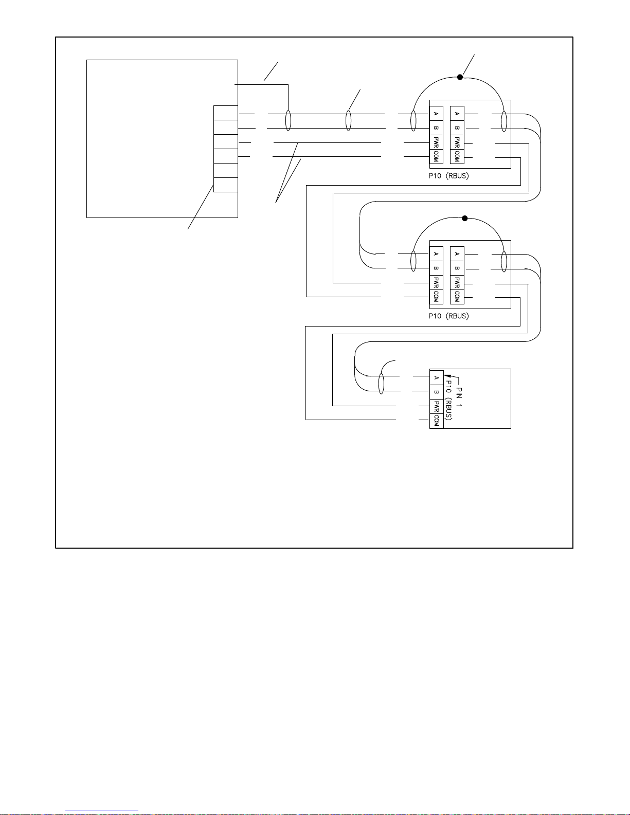
1.10.2 Communication Cable
Specifications
RBUS Connections A and B
For the RBUS communication connections A and B to
the Model RXT transfer switch, optional PIM and/or
optional LCM or load shed kit, use 20 AWG shielded,
twisted-pair communication cable. Belden #9402
(two-pair) or Belden #8762 (single-pair) or equivalent
and use the second pair for the PWR and COM
connections.
D For the longercable runs shownin the lasttwo rows of
Figure 1-23, use 12 or 14 AWG cable for PWR and
COM, and use the 20 AWG communication cable
specified above for the A and B connections only. In
this case, single-pair communication cable such as
Belden #8762 can be used for the A and B
connections.
cable is recommended.
For outdoor installations, including those with buried
cables and/or conduit, use outdoor-rated Belden
#1075A or equivalent 20 AWG shielded, twisted-pair
communication cable.
1.10.3 System Connections with
Accessory Modules
See Figure 1-24 through Figure 1-28 for connection
options with accessory modules. Accessory modules
can include one Model RXT transfer switch, one
PWR and COM Connections
For the PWR and COM connections, the cable size and
maximum cable length depends on the number of
modules connected. See Figure 1-23.
D For short cable runs shown in the first two rows of
Figure 1-23, use one pair in the two-pair
communication cable for the A and B connections,
programmable interface module (PIM) and/or one load
control module (LCM) or load shed kit. Note the cable
shield connections shown in Figure 1-24.
The maximum cable length depends on the number of
optional modules connected. See Figure 1-23 for the
maximum cablelengths with 1,2, or 3modules per cable
run.
tp6803
TP-6803 1/1526 Section 1 Installation
Maximum length per run, meters (ft.)
Indoor or
Outdoor
Cable Size for PWR and COM Connections
Installation
20 AWG Belden #9402 or equivalent, two-pair Indoor
20 AWG Belden #1075A or equivalent, two-pair Outdoor
14 AWG * —
12 AWG * —
* Use 12 or 14 AWG cable for PWR and COM connections only. For RBUS connections A and B, use shielded, twisted pair communication
cable specified in Section 1.10.2.
1 Module 2 Modules 3 Modules
61 (200) 31 (100) 21 (67)
61 (200) 31 (100) 21 (67)
152 (500) 152 (500) 122 (400)
152 (500) 152 (500) 152 (500)
Number of Modules per Run
Figure 1-23 Total Cable Lengths for PWR and COM Connections
Generator Set
RBUS
12 VDC
1
GND
A
B
PWR
COM
4
3
A
B
PWR
COM
2
4
3
RXT
A
B
PWR
COM
A
B
PWR
COM
PIM
A
B
PWR
COM
A
B
PWR
COM
Note: See Section 1.10.2, Cable Specifications.
1. Generator set terminal block. See Figure 2-4 for location. Check the decal on the generator set for terminal block connections.
2. Connect one end of each cable shield to GROUND at the generator set.
3. Communication cable Belden #9402 or equivalent 20 AWG shielded, twisted-pair cable.
4. Connect shields together as shown.
5. Leave one end of each cable shield disconnected at the last device.
Figure 1-24 Accessory Module Communication Connection Details
TP-6803 1/15 27Section 1 Installation
5
A
B
PWR
COM
LCM
or load
shed kit
5
2
4
Generator Set
RBUS
12 VDC
1
GND
A
B
PWR
COM
4
3
A
B
PWR
COM
3
RXT
A
B
PWR
COM
6
A
B
PWR
COM
PIM
A
B
PWR
COM
5
A
B
PWR
COM
A
B
PWR
COM
LCM
or load
shed kit
Note: See Section 1.10.2, Cable Specifications.
1. Generator set terminal block. See Figure 2-4 for location. Check the decal on the generator set for terminal block connections.
2. Connect one end of each cable shield to GROUND at the generator set.
3. Communication cable Belden #8762 or equivalent 20 AWG shielded, twisted-pair cable (one pair).
4. Connect shields together as shown.
5. Leave one end of each cable shield disconnected at the last device.
6. 12 AWG or 14 AWG leads for PWR and COM.
Figure 1-25 Accessory Module Connections with 12--14 AWG Power Leads
TP-6803 1/1528 Section 1 Installation
 Loading...