

Page 1
Installation
Residential/Commercial Generator Sets
Models:
12RESM1
12/17/18RESL
12/17/18RESNT
12/18RESHD
Controller:
DC-RET Digital Control
TP-6516 4/09d
Page 2

California Proposition 65
WARNING
Engine exhaust from this product contains chemicals
known to the State of California to cause cancer, birth
defects, or other reproductive harm.
Product Identification Information
Generator Set Identification Numbers
Record the product identification numbers from the
generator set nameplate(s).
Model Designation
Specification Number
Serial Number
Accessory Number Accessory Description
Engine Identification
Record the product identification information from the
engine nameplate.
Manufacturer
Model Designation
Serial Number
Controller Identification
Record the controller description from the generator set
operation manual, spec sheet, or sales invoice.
Controller Description
Page 3

Table of Contents
Product Identification Information 2..........................................................
Safety Precautions and Instructions 5........................................................
Introduction 9...............................................................................
Service Assistance 11........................................................................
Section 1 Installation 13......................................................................
1.1 General 13..............................................................
1.2 Lifting 13...............................................................
1.3 Generator Set Inspection 13...............................................
1.4 Location and Mounting 13.................................................
1.4.1 Exhaust Requirements 18.........................................
1.4.2 Air Requirements 18..............................................
1.5 Power Supply 18.........................................................
1.6 Fuel Requirements 19....................................................
1.6.1 Fuel Supply 19..................................................
1.6.2 Fuel Pipe Size 20................................................
1.7 Fuel Conversion 20......................................................
1.7.1 Fuel Conversion 20..............................................
1.8 Electrical Connections 22.................................................
1.8.1 AC Connections 22...............................................
1.8.2 Remote Start Connection 23.......................................
1.8.3 Grounding 23....................................................
1.8.4 Battery Charger 23...............................................
1.9 Battery 24...............................................................
1.10 Carburetor Heater (optional) 26............................................
1.11 Prestart Installation Check 27..............................................
1.12 Startup Notification 27....................................................
Section 2 Wiring Diagrams 29................................................................
Appendix A Abbreviations 35................................................................
TP-6516 4/09 Table of Contents 3
Page 4

Notes
TP-6516 4/094
Page 5
Safety Precautions and Instructions
IMPORTANT SAFETY INSTRUCTIONS.
Electromechanical equipment,
including generator sets, transfer
switches, switchgear, and accessories,
can cause bodily harm and pose
life-threatening danger when
improperly installed, operated, or
maintained. To prevent accidents be
aware of potential dangers and act
safely. Read and follow all safety
precautions and instructions. SAVE
THESE INSTRUCTIONS.
This manual has several types of safety
precautions and instructions: Danger,
Warning, Caution, and Notice.
DANGER
Danger indicates the presence of a
hazard that will cause severe
personal injury, death,or
substantial property damage.
WARNING
Warning indicates the presence of a
hazard that can cause severe
personal injury, death, or
substantial property damage.
CAUTION
Caution indicates the presence of a
hazard that will or can cause minor
personal injury or property damage.
NOTICE
Notice communicates installation,
operation, or maintenance information
that is safety related but not hazard
related.
Safety decals affixed to the equipment
in prominent places alert the operator
or service technician to potential
hazards and explain how to act safely.
The decals are shown throughout this
publication to improve operator
recognition. Replace missing or
damaged decals.
Accidental Starting
WARNING
Accidental starting.
Can cause severe injury or death.
Disconnect the battery cables before
working on the generator set.
Remove the negative (--) lead first
when disconnecting the battery.
Reconnect the negative (--) lead last
when reconnecting the battery.
Disabling the generator set.
Accidental starting can cause
severe injury or death. Before
working on the generator set or
connected equipment, disable the
generator set as follows: (1) Move the
generator set master switch to the OFF
position. (2) Disconnect the power to
the battery charger. (3) Remove the
battery cables, negative (--) lead first.
Reconnect the negative (--) lead last
when reconnecting the battery. Follow
these precautions to prevent starting of
the generator set by an automatic
transfer switch, remote start/stop
switch, or engine start command from a
remote computer.
Battery
WARNING
Sulfuric acid in batteries.
Can cause severe injury or death.
Wear protective goggles and
clothing. Battery acid may cause
blindness and burn skin.
WARNING
Explosion.
Can cause severe injury or death.
Relays in the battery charger
cause arcs or sparks.
Locate the battery in a well-ventilated
area. Isolate the battery charger from
explosive fumes.
Battery electrolyte is a diluted
sulfuric acid. Battery acid can cause
severe injury or death. Battery acid
can cause blindness and burn skin.
Always wear splashproof safety
goggles, rubber gloves, and boots
when servicing the battery. Do not
open a sealed battery or mutilate the
battery case. If battery acid splashes in
the eyes or on the skin, immediately
flush the affected area for 15 minutes
with large quantities of clean water.
Seek immediate medical aid in the case
of eye contact. Never add acid to a
battery after placing the battery in
service, as this may result in hazardous
spattering of battery acid.
Battery acid cleanup. Battery acid
can cause severe injury or death.
Battery acid is electrically conductive
and corrosive. Add 500 g (1 lb.) of
bicarbonate of soda (baking soda) to a
containerwith4L(1gal.)ofwaterand
mix the neutralizing solution. Pour the
neutralizing solution on the spilled
battery acid and continue to add the
neutralizing solution to the spilled
battery acid until all evidence of a
chemical reaction (foaming) has
ceased. Flush the resulting liquid with
water and dry the area.
TP-6516 4/09 5Safety Precautions and Instructions
Page 6
Battery gases. Explosion can cause
severe injury or death. Battery gases
can cause an explosion. Do not smoke
or permit flames or sparks to occur near
a battery at any time, particularly when
it is charging. Do not dispose of a
battery in a fire. To prevent burns and
sparks that could cause an explosion,
avoid touching the battery terminals
with tools or other metal objects.
Remove all jewelry before servicing the
equipment. Discharge static electricity
from your body before touching
batteries by first touching a grounded
metal surface away from the battery. To
avoid sparks, do not disturb the battery
charger connections while the battery
is charging. Always turn the battery
charger off before disconnecting the
battery connections. Ventilate the
compartments containing batteries to
prevent accumulation of explosive
gases.
Battery short circuits. Explosion
can cause severe injury or death.
Short circuits can cause bodily injury
and/or equipment damage.
Disconnect the battery before
generator set installation or
maintenance. Remove all jewelry
before servicing the equipment. Use
tools with insulated handles. Remove
the negative (--) lead first when
disconnecting the battery. Reconnect
the negative (--) lead last when
reconnecting the battery. Never
connect the negative (--) battery cable
to the positive (+) connection terminal
of the starter solenoid. Do not test the
battery condition by shorting the
terminals together.
Engine Backfire/Flash
Fire
WARNING
Fire.
Can cause severe injury or death.
Do not smoke or permit flames or
sparks near fuels or the fuel system.
Servicing the fuel system. A flash
fire can cause severe injury or death.
Do not smoke or permit flames or
sparks near the carburetor, fuel line,
fuel filter, fuel pump, or other potential
sources of spilled fuels or fuel vapors.
Catch fuels in an approved container
when removing the fuel line or
carburetor.
Combustible materials. A fire can
cause severe injury or death.
Generator set engine fuels and fuel
vapors are flammable and explosive.
Handle these materials carefully to
minimize the risk of fire or explosion.
Equip the compartment or nearby area
with a fully charged fire extinguisher.
Select a fire extinguisher rated ABC or
BC for electrical fires or as
recommended by the local fire code or
an authorized agency. Train all
personnel on fire extinguisher
operation and fire prevention
procedures.
Exhaust System
WARNING
Carbon monoxide.
Can cause severe nausea,
fainting, or death.
The exhaust system must be
leakproof and routinely inspected.
Generator set operation. Carbon
monoxide can cause severe nausea,
fainting, or death. Carbon monoxide
is an odorless, colorless, tasteless,
nonirritating gas that can cause death if
inhaled for even a short time. Avoid
breathing exhaust fumes when working
on or near the generator set. Never
operate the generator set inside a
building. Never operate the generator
set where exhaust gas could seep
inside or be drawn into a potentially
occupied building through windows, air
intake vents, or other openings.
Carbon monoxide symptoms.
Carbon monoxide can cause severe
nausea, fainting, or death. Carbon
monoxide is a poisonous gas present in
exhaust gases. Carbon monoxide is an
odorless, colorless, tasteless,
nonirritating gas that can cause death if
inhaled for even a short time. Carbon
monoxide poisoning symptoms include
but are not limited to the following:
D Light-headedness, dizziness
D Physical fatigue, weakness in
joints and muscles
D Sleepiness, mental fatigue,
inability to concentrate
or speak clearly, blurred vision
D Stomachache, vomiting, nausea
If experiencing any of these symptoms
and carbon monoxide poisoning is
possible, seek fresh air immediately
and remain active. Do not sit, lie down,
or fall asleep. Alert others to the
possibility of carbon monoxide
poisoning. Seek medical attention if
the condition of affected persons does
not improve within minutes of breathing
fresh air.
Fuel System
WARNING
Explosive fuel vapors.
Can cause severe injury or death.
Use extreme care when handling,
storing, and using fuels.
Gas fuel leaks. Explosive fuel
vapors can cause severe injury or
death. Fuel leakage can cause an
explosion. Check the LP vapor gas or
natural gas fuel system for leakage by
using a soap and water solution with
the fuel system test pressurized to
6--8 ounces per square inch
(10--14 inches water column). Do not
use a soap solution containing either
ammonia or chlorine because both
prevent bubble formation. A successful
test depends on the ability of the
solution to bubble.
Servicing the air cleaner. A sudden
backfire can cause severe injury or
death. Do not operate the generator
set with the air cleaner removed.
TP-6516 4/096 Safety Precautions and Instructions
Page 7
Hazardous Noise
CAUTION
Hazardous noise.
Can cause hearing loss.
Never operate the generator set
without a muffler or with a faulty
exhaust system.
Engine noise. Hazardous noise can
cause hearing loss. Generator sets
not equipped with sound enclosures
can produce noise levels greater than
105 dBA. Prolonged exposure to noise
levels greater than 85 dBA can cause
permanent hearing loss. Wear hearing
protection when near an operating
generator set.
Hazardous Voltage/
Moving Parts
WARNING
Hazardous voltage.
Can cause severe injury or death.
Operate the generator set only when
all guards and electrical enclosures
areinplace.
WARNING
Hazardous voltage.
Backfeed to the utility system can
cause property damage, severe
injury, or death.
If the generator set is used for
standby power, install an automatic
transfer switch to prevent inadvertent
interconnection of standby and
normal sources of supply.
Moving parts.
CAUTION
Welding the generator set.
Can cause severe electrical
equipment damage.
Never weld components of the
generator set without first
disconnecting the battery, controller
wiring harness, and engine electronic
control module (ECM).
Grounding electrical equipment.
Hazardous voltage can cause
severe injury or death. Electrocution
is possible whenever electricity is
present. Ensure you comply with all
applicable codes and standards.
Electrically ground the generator set,
transfer switch, and related equipment
and electrical circuits. Turnoff the main
circuit breakers of all power sources
before servicing the equipment. Never
contact electrical leads or appliances
when standing in water or on wet
ground because these conditions
increase the risk of electrocution.
Welding on the generator set. Can
cause severe electrical equipment
damage. Before welding on the
generator set perform the following
steps: (1) Remove the battery cables,
negative (--) lead first. (2) Disconnect
all engine electronic control module
(ECM) connectors. (3) Disconnect all
generator set controller and voltage
regulator circuit board connectors.
(4) Disconnect the engine batterycharging alternator connections.
(5) Attach the weld ground connection
close to the weld location.
Connecting the battery and the
battery charger. Hazardous voltage
can cause severe injury or death.
Reconnect the battery correctly,
positive to positive and negative to
negative, to avoid electrical shock and
damage to the battery charger and
battery(ies). Have a qualified
electrician install the battery(ies).
Short circuits. Hazardous
voltage/current can cause severe
injury or death. Short circuits can
cause bodily injury and/or equipment
damage. Do not contact electrical
connections with tools or jewelry while
making adjustments or repairs.
Remove all jewelry before servicing the
equipment.
Electrical backfeed to the utility.
Hazardous backfeed voltage can
cause severe injury or death. Install
a transfer switch in standby power
installations to prevent the connection
of standby and other sources of power.
Electrical backfeed into a utility
electrical system can cause severe
injury or death to utility personnel
working on power lines.
WARNING
Airborne particles.
Can cause severe injury or
blindness.
Wear protective goggles and clothing
when using power tools, hand tools,
or compressed air.
Heavy Equipment
WARNING
Unbalanced weight.
Improper lifting can cause severe
injury or death and equipment
damage.
Do not use lifting eyes.
Lift the generator set using lifting bars
inserted through the lifting holes on
the skid.
TP-6516 4/09 7Safety Precautions and Instructions
Page 8

Hot Parts
WARNING
Hot engine and exhaust system.
Can cause severe injury or death.
Do not work on the generator set until
it cools.
Servicing the exhaust system. Hot
parts can cause severe injury or
death. Do not touch hot engine parts.
The engine and exhaust system
components become extremely hot
during operation.
Servicing the engine heater. Hot
parts can cause minor personal
injury or property damage. Install the
heater before connecting it to power.
Operating the heater before installation
can cause burns and component
damage. Disconnect power to the
heater and allow it to cool before
servicing the heater or nearby parts.
Notice
NOTICE
Canadian installations only.For
standby service connect the output of
the generator set to a suitably rated
transfer switch in accordance with
Canadian Electrical Code, Part 1.
TP-6516 4/098 Safety Precautions and Instructions
Page 9
Introduction
This manual provides installation instructions for 12, 17,
and 18 kW residential/commercial generator sets
equipped with the Kohlerr DC-RET Digital Control.
Refer to TP-6517, Operation Manual, for generator set
operation and maintenance instructions.
The generator set is approved for use in stationary
applications in locations served by a reliable utility
power source.
Have an authorized distributor/dealer install the
generator set outdoors according to the instructions in
this manual. The generator set installation must comply
with the National Electrical Code (NEC) and local code
requirements. Do not install this generator set indoors.
Information in this publication represents data available
at the time of print. Kohler Co. reserves the right to
change this publication and the products represented
without notice and without any obligation or liability
whatsoever.
Read this manual and carefully follow all procedures
and safety precautions to ensure proper equipment
operation and to avoid bodily injury. Read and follow the
Safety Precautions and Instructions section at the
beginning of this manual.
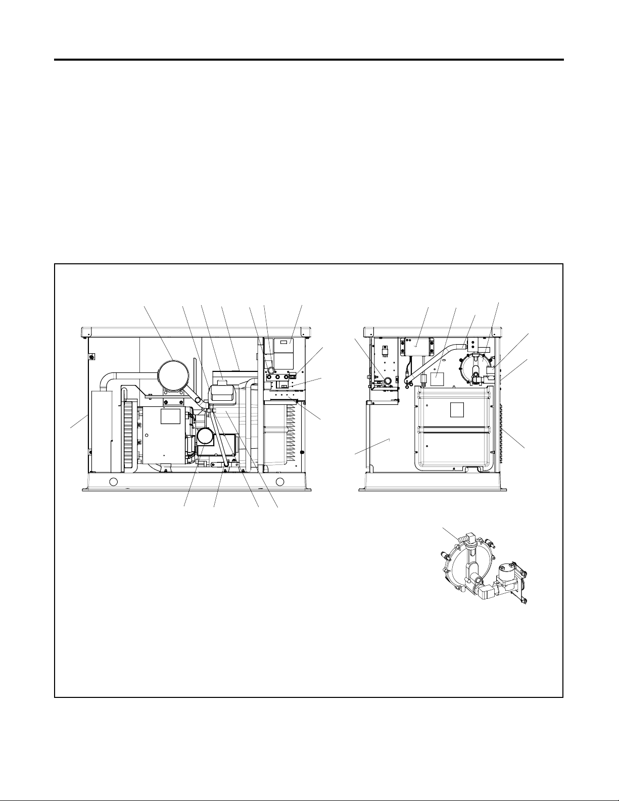
See Figure 1 or Figure 2 for generator set component
locations.
19
18
75 61234
16
8
17 20
See
Detail
21
22
15
14 13
1. Muffler
2. Oil check
3. Oil fill
4. Air cleaner
5. Fuses
6. RS-232 connector (for application program updates)
7. Controller user interface
8. Generator set master switch (RUN-OFF/RESET-AUTO)
9. Load circuit breaker
10. Field-connection terminal block location
11. Spark plug locations (both sides)
12. Oil drain hose
13. Oil drain valve
12
9
10
24
11
14. Oil filter
15. Exhaust
16. Equipment ground
17. Battery charger
18. DSAI lead location
19. LP fuel orifice location
20. Gas regulator assembly
21. Fuel solenoid valve
22. Fuel inlet
23. Air intake
24. Engine starting battery location
(battery purchased separately)
23
ADV-7466-
19
Fuel system detail
Figure 1 Generator Set Component Locations, 12 kW Models
TP-6516 4/09 9
Page 10
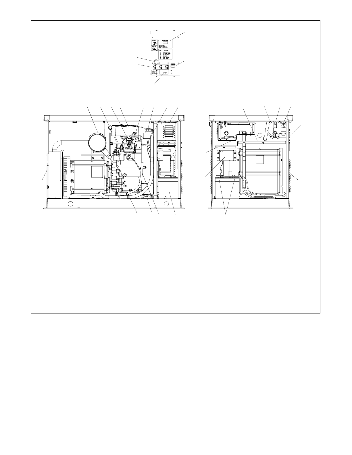
Control detail, top view
8
17
12
9
11
10
7
12 5420
3
6
See control detail
18
19
21
22
26
25
23
ADV-7341A-B
13 24
16
1415
1. Muffler
2. Oil check
3. Oil fill
4. Air cleaner
5. Spark plug locations (both sides)
6. Oil filter
7. Oil cooler location
8. DC-RET Digital Control display
9. Generator set master switch (RUN-OFF/RESET-AUTO)
10. Line circuit breaker
11. Fuses
12. RS-232 connector (for application program updates)
13. Engine starting battery location (battery purchased separately)
14. Oil drain hose
15. Nameplate location (on base)
16. Oil drain valve
17. Exhaust outlet
18. Field-connection terminal block location
19. LP fuel orifice location (inside hose fitting)
20. Gas regulator assembly
21. DSAI leads
22. Fuel inlet
23. Air intake
24. Battery cables
25. Battery charger
26. 120 VAC receptacle for battery charger
Figure 2 Generator Set Component Locations, 17/18 kW Models
TP-6516 4/0910
Page 11

Service Assistance
For professional advice on generator set power
requirements and conscientious service, please contact
your nearest Kohler distributor or dealer.
D Consult the Yellow Pages under the heading
Generators—Electric.
D Visit the Kohler Power Systems website at
KohlerPower.com.
D Look at the labels and stickers on your Kohler product
or review the appropriate literature or documents
included with the product.
D Call toll free in the US and Canada 1-800-544-2444.
D Outside the US and Canada, call the nearest regional
office.
Headquarters Europe, Middle East, Africa
(EMEA)
Kohler Power Systems
3 rue de Brennus
93200 Saint Denis
France
Phone: (33) 1 49 178300
Fax: (33) 1 49 178301
Asia Pacific
Power Systems Asia Pacific Regional Office
Singapore, Republic of Singapore
Phone: (65) 6264-6422
Fax: (65) 6264-6455
China
North China Regional Office, Beijing
Phone: (86) 10 6518 7950
(86) 10 6518 7951
(86) 10 6518 7952
Fax: (86) 10 6518 7955
East China Regional Office, Shanghai
Phone: (86) 21 6288 0500
Fax: (86) 21 6288 0550
India, Bangladesh, Sri Lanka
India Regional Office
Bangalore, India
Phone: (91) 80 3366208
(91) 80 3366231
Fax: (91) 80 3315972
Japan, Korea
North Asia Regional Office
Tokyo, Japan
Phone: (813) 3440-4515
Fax: (813) 3440-2727
TP-6516 4/09 11
Page 12

Notes
TP-6516 4/0912
Page 13

Section 1 Installation
1.1 General
Have an authorized distributor/dealer install the
generator set outdoors according to the instructions in
this manual. The generator set installation must comply
with the National Electrical Code (NEC) and local code
requirements. Do not install this generator set indoors.
Use the generator set and transfer switch dimension
drawings and wiring diagrams for installation.
1.2 Lifting
WARNING
Unbalanced weight.
Improper lifting can cause severe
injury or death and equipment
damage.
Do not use lifting eyes.
Lift the generator set using lifting bars
inserted through the lifting holes on
the skid.
1.3 Generator Set Inspection
Complete a thorough inspection of the generator set.
Check for the following:
1. Inspect the generator set for loose or damaged
parts or wires. Repair or tighten any loose parts
before installation.
2. Check the engine oil. Fill, if necessary, with the
recommended viscosity and grade of oil. Use
synthetic oil, API (American Petroleum Institute)
Service Class SG or higher. See TP-6517,
Operation Manual, for additional information.
1.4 Location and Mounting
See Figure 1-2 (12 kW) or Figure 1-4 (17/18 kW) for the
generator set dimensions and fuel and electric inlet
locations. The drawing dimensions are shown in
millimeters, with inches in brackets.
Install the generator set outdoors. Provide the minimum
clearance around the generator set shown in Figure 1-3
or Figure 1-5. Locate the generator set so that the hot
exhaust does not blow on plants or other combustible
materials. Do not install the generator set where
exhaust gas could accumulate and seep inside or be
drawn into a potentially occupied building.
Approximate generator set weights are shown in
Figure 1-1. Use lifting bars inserted through the holes in
the skid to lift the unit. See Figure 1-2 or Figure 1-4 for
lifting hole locations.
Model Weight, kg (lb.)
12 kW 186 (410)
17/18 kW 227 (500)
Figure 1-1 Approximate Weights
The generator set is shipped on a plastic mounting pad.
Prepare a flat, level mounting area covered with a weed
barrier and gravel as shown in Figure 1-5. Set the
plastic mounting pad directly on the gravel. Do not
install the mounting pad directly on grass.
TP-6516 4/09 13Section 1 Installation
Page 14

Note: Fuel system may differ from drawing. See Section 1.7.
Figure 1-2 Generator Set Mounting Details and Dimensions, 12 kW Models, ADV-7466, Sheet 1
TP-6516 4/0914 Section 1 Installation
Page 15

Figure 1-3 Generator Set Clearances, 12 kW Models, ADV-7466, Sheet 2
TP-6516 4/09 15Section 1 Installation
Page 16

Figure 1-4 Generator Set Mounting Details and Dimensions, 17/18 kW Models, ADV-7341-B, Sheet 1
TP-6516 4/0916 Section 1 Installation
Page 17

Figure 1-5 Generator Set Clearances, 17/18 kW Models, ADV-7341-B, Sheet 2
TP-6516 4/09 17Section 1 Installation
Page 18

1.4.1 Exhaust Requirements
WARNING
Carbon monoxide.
Can cause severe nausea,
fainting, or death.
The exhaust system must be
leakproof and routinely inspected.
Generator set operation. Carbon monoxide can cause
severe nausea, fainting, or death. Carbon monoxide is an
odorless, colorless, tasteless, nonirritating gas that can cause
death if inhaled for even a short time. Avoid breathing exhaust
fumes when working on or near the generator set. Never
operate the generator set inside a building. Never operate the
generator set where exhaust gas could seep inside or be
drawn into a potentially occupied building through windows, air
intake vents, or other openings.
The exhaust system is complete for generator sets
installed outdoors. Do not install this generator set
indoors.
Figure 1-6 gives the exhaust flow and temperature at
rated load. The engine exhaust mixes with the
generator set cooling air at the exhaust end of the
enclosure. Mount the generator set so that the hot
exhaust does not blow on plants or other combustible
materials. Maintain the clearances shown in Figure 1-5.
Exhaust System 60 Hz
Exhaust flow at rated kW,
3
/min. (cfm)
m
12 kW 3.8 (135)
17/18 kW 5.3 (187)
Exhaust gas temperature exiting
the enclosure at rated kW, _C(_F)
216 (420)
Figure 1-6 Exhaust Flow and Temperature
1.4.2 Air Requirements
The generator set requires correct air flow for cooling
and combustion. The inlet and outlet openings in the
sound enclosure provide the cooling and combustion
air. Figure 1-7 shows the locations of the cooling air
intake and exhaust vents. Inspect the air inlet and outlet
openings inside and outside the housing to ensure that
the air flow is not blocked.
1
2
1. Exhaust outlet
2. Alternator air intake (both sides)
3. Engine air intake
3
3
GM51561
Figure 1-7 Cooling Air Intake and Exhaust
Model
12 kW
17/18
kW
Air Requirements, m
Cooling
Hz
60 26.9 (950) 1.1 (39.2) 28.0 (990)
50 22.4 (790) 0.9 (32.6) 23.4 (826)
60 28.0 (989) 1.62 (57.3) 29.6 (1045)
50 22.6 (798) 1.42 (50.1) 24.0 (848)
Air
Combustion
Air
3
/min. (cfm)
Total Inlet
Air
Figure 1-8 Air Requirements
1.5 Power Supply
Power must be supplied from a source that is GFCI
protected to the generator set location for the battery
charger and the optional carburetor heater. See
Section 1.8. Connect power from a circuit on the
essential loads panel to the 120-VAC receptacles.
Figure 1-9 lists the power requirements for the battery
charger and accessories.
Power Requirement, Max.
Equipment
Battery charger 192 1.6
Carburetor heater:
12 kW
17/18 kW
Battery heater 110 0.92
Figure 1-9 Power Requirements
Watts Amps Volts
38 0.32
40 0.34
120
TP-6516 4/0918 Section 1 Installation
Page 19

1.6 Fuel Requirements
The generator set operates using natural gas or LP
vapor fuel. The generator set is EPA-certified for both
natural gas and LP vapor fuels.
The fuel system installation must comply with the NEC
and local codes.
1.6.1 Fuel Supply
Because of variable climates and geographical
considerations, contact the local fuel supplier for fuel
system planning and installation. Figure 1-10 lists the
recommended fuel ratings and other fuel supply
information for natural gas and LP vapor fuels.
Fuel types Natural Gas LP Vapor
Fuel supply inlet 1/2 NPT
Fuel supply pressure,
kPa (in. H
Fuel supply pressure,
kPa (in. H
Fuel flow rate, Btu/hr.,
12 kW
Fuel flow rate, Btu/hr.,
17/18 kW
Nominal Fuel Rating, Btu/ft
Natural gas 1000
LP vapor 2500
Figure 1-10 Fuel Supply
Verify that the output pressure from the primary gas
utility (or LP tank) pressure regulator is within the range
shown in Figure 1-10 and that the utility gas meter flow
rate is sufficient to supply the generator set at rated load
plus all other gas-consuming appliances. See
Figure 1-11 or Figure 1-12 for fuel consumption.
Contact the fuel supplier for flow rate information or a
gas meter upgrade.
O), 12 kW
2
O), 17/18 kW
2
1.3--2.7 (5-11) 1.7--2.7 (7-11)
1.7--2.7 (7-11)
193000 203000
242000 280000
3
Fuel Consumption at % Rated Load
Natural Gas, m3/hr. (cfh)
100% 5.9 (209)
75% 4.8 (168)
50% 3.6 (127)
25% 2.4 (85)
LP Vapor, m3/hr. (cfh)
100% 3.1 (108)
75% 2.5 (87)
50% 1.9 (65)
25% 1.2 (44)
LP vapor conversion factors:
Nominal fuel rating:
3
=1lb.
8.58 ft.
3
0.535 m
36.39 ft.
Natural gas: 37 MJ/m
LP vapor: 93 MJ/m
=1kg
3
= 1 gal.
3
(1000 Btu/ft.3)
3
(2500 Btu/ft.3)
Figure 1-11 Fuel Consumption, 12 kW Models
Fuel Consumption at % Rated Load
Natural Gas, m3/hr. (cfh)
100% 6.9 (242)
75% 5.8 (204)
50% 4.4 (155)
25% 3.4 (120)
LP Vapor, m3/hr. (cfh)
100% 3.2 (112)
75% 2.7 (96)
50% 2.1 (74)
25% 1.6 (57)
LP vapor conversion factors:
Nominal fuel rating:
3
=1lb.
8.58 ft.
3
0.535 m
36.39 ft.
Natural gas: 37 MJ/m
LP vapor: 93 MJ/m
=1kg
3
= 1 gal.
3
(1000 Btu/ft.3)
3
(2500 Btu/ft.3)
Figure 1-12 Fuel Consumption, 17/18 kW Models
See Figure 1-2 or Figure 1-4 for the location of the fuel
inlet connection. Use flexible sections to prevent fuel
line breakage caused by vibration. Hold the fuel
solenoid valve with a wrench when tightening the fuel
connections. Protect all fuel lines from machinery or
equipment contact, adverse weather conditions, and
environmental damage.
TP-6516 4/09 19Section 1 Installation
Page 20

1.6.2 Fuel Pipe Size
1.7 Fuel Conversion
Ensure that the natural gas pipe size and length meet
the specifications in Figure 1-13 or Figure 1-14.
Measure the pipe length from the primary gas pressure
regulator to the pipe connection on the generator set
fuel inlet. Add 2.4 m (8 ft.) to the measured length for
each 90 degree elbow. Compare the total pipe length
with the chart in Figure 1-13 or Figure 1-14 to find the
required pipe size.
Contact the local LP provider for LP installation
information.
Maximum Pipe Length, m (ft.) Pipe Size, in. NPT
9.2 (30) 3/4
30.0 (100) 1
68.6 (225) 11/4
Figure 1-13 12 kW Models, Fuel Pipe Size, Natural
Gas
Minimum Gas Pipe Size Recommendation, in. NPT
Pipe Length,
m (ft.)
8 (25) 1 3/4
15 (50) 1 1
30 (100) 11/4 1
46 (150) 11/4 11/4
61 (200) 11/4 11/4
Natural Gas
(242,000 Btu/hr.)
LP Vapor
(280,000 Btu/hr.)
Figure 1-14 17/18 kW Models, Fuel Pipe Size,
Natural Gas
The multi-fuel system allows conversion from natural
gas to LP vapor (or vice-versa) in the field while
maintaining emissions-standard compliance. A trained
technician or authorized distributor/dealer can convert
the fuel system.
WARNING
Accidental starting.
Can cause severe injury or death.
Disconnect the battery cables before
working on the generator set.
Remove the negative (--) lead first
when disconnecting the battery.
Reconnect the negative (--) lead last
when reconnecting the battery.
Disabling the generator set. Accidental starting can
cause severe injury or death. Before working on the
generator set or connected equipment, disable the generator
set as follows: (1) Move the generator set master switch to the
OFF position. (2) Disconnect the power to the battery charger.
(3) Remove the battery cables, negative (--) lead first.
Reconnect the negative (--) lead last when reconnecting the
battery. Follow these precautions to prevent starting of the
generator set by an automatic transfer switch, remote
start/stop switch, or engine start command from a remote
computer.
WARNING
Explosive fuel vapors.
Can cause severe injury or death.
Use extreme care when handling,
storing, and using fuels.
1.7.1 Fuel Conversion
For LP vapor fuel, an orifice is used in the fuel line. The
unit is typically shipped set up for natural gas, with the
loose orifice tied near the fuel line. To convert to LP
vapor, install the orifice and disconnect the spark
advance leads as described below. See Figure 1-15 for
the fuel system component locations.
TP-6516 4/0920 Section 1 Installation
Page 21

Procedure to Convert from NG to LP
1. Place the generator set master switch in the OFF
position.
2. Disconnect the power to the battery charger.
3. Disconnect the generator set engine starting
battery, negative (--) lead first.
4. Turn off the fuel supply.
5. Remove the hose clamp and fuel hose from the
hose fitting. See Figure 1-15.
6. Place the orifice into the hose fitting. See
Figure 1-16.
1
2
3
Fuel System Detail
1
2
3
1. LP orifice 2. Hose fitting 3. Regulator
tp6514
Figure 1-16 LP Fuel Orifice Installation
4
7. Slide the hose onto the hose fitting and secure it
with the clamp.
8. Disconnect the digital spark-advance module
(DSAI) leads for LP. (Connect the leads for natural
5
2
6
3
4
gas.) See Figure 1-17 and Figure 1-18.
Fuel DSAI Leads
Natural Gas Connect
LP Disconnect
Figure 1-17 DSAI Connection
1
GM51561A-D
1. Hose fitting (LP orifice fits inside; see Figure 1-16)
2. Regulator
3. Fuel valve
4. Fuel inlet, 1/2 in. NPT female
5. Fuel hose with clamp
6. DSAI connector location (see Figure 1-18)
Figure 1-15 Fuel System Components, Air Inlet Side,
17/18 kW Shown
1. DSAI leads 65 and N5: connect for natural gas,
disconnect for LP
Figure 1-18 Digital Spark Advance (DSAI) Leads
(located in generator set air intake area)
TP-6516 4/09 21Section 1 Installation
tp6514
Page 22

9. Connect and turn on the new fuel supply.
10. Check that the generator set master switch is in the
OFF position.
NOTICE
Canadian installations only. For standby service connect
the output of the generator set to a suitably rated transfer
switch in accordance with Canadian Electrical Code, Part 1.
11. Reconnect the generator set engine starting
battery leads, negative (--) lead last.
12. Reconnect power to the battery charger.
13. Start the generator set by moving the generator set
master switch to the RUN position.
14. Check for leaks using a gas leak detector.
15. Move the generator set master switch to the OFF/
RESET position to shut down the generator set.
To convert from LP vapor to natural gas, remove the fuel
orifice and connect the DSAI leads together.
1.8 Electrical Connections
WARNING
Hazardous voltage.
Backfeed to the utility system can
cause property damage, severe
injury, or death.
If the generator set is used for
standby power, install an automatic
transfer switch to prevent inadvertent
interconnection of standby and
normal sources of supply.
Grounding electrical equipment. Hazardous voltage can
cause severe injury or death. Electrocution is possible
whenever electricity is present. Ensure you comply with all
applicable codes and standards. Electrically ground the
generator set, transfer switch, and related equipment and
electrical circuits. Turn off the main circuit breakers of all
power sources before servicing the equipment. Never contact
electrical leads or appliances when standing in water or on wet
ground because these conditions increase the risk of
electrocution.
Electrical backfeed to the utility. Hazardous backfeed
voltage can cause severe injury or death. Install a transfer
switch in standby power installations to prevent the connection
of standby and other sources of power. Electrical backfeed
into a utility electrical system can cause severe injury or death
to utility personnel working on power lines.
Have an authorized distributor/dealer or a licensed
electrician make the following electrical connections.
Verify that the electrical installation complies with the
National Electrical Code (NEC) and all applicable local
codes. Ground the generator set from the GRD terminal
inside the controller compartment according to
applicable codes.
1.8.1 AC Connections
The generator set is equipped with a field-connection
terminal block located in the air inlet area near the
junction box. See Figure 1-19 and Figure 1-20. Also
see Section 2, Wiring Diagrams.
Refer to the transfer switch specifications and
Figure 1-20 for the acceptable cable sizes. Route AC
leads through flexible conduit. Ensure that the leads
and conduit do not interfere with the operation of the
generator set or obstruct the service areas.
The electrical installation must comply with the National
Electrical Code (NEC) and all applicable local codes.
Connection Procedure
See Figure 1-20. Leads have been factory-installed
from the junction box to the terminal block for easier field
wiring. Refer to the decal near the terminal block for
connections.
1. Connect the leads from the transfer switch
emergency source lugs to the L1 and L2
connections on the generator set terminal block.
2. Connect the neutral (L0) and ground (GRD) leads
from the ATS and the main panel to the
corresponding connection points on the terminal
block. See Section 1.8.3, Grounding.
3. The terminal block kit includes 120VAC
receptacles for the battery charger and optional
carburetor heater. Connect utility power to the
terminal block as shown. Connect to a circuit that is
supplied by the generator set if utility power is lost.
TP-6516 4/0922 Section 1 Installation
Page 23

1
1.8.2 Remote Start Connection
Connect engine start leads from terminals 3 and 4 to the
automatic transfer switch’s engine start terminals or to
an optional remote start/stop switch. Route the engine
2
start leads through separate conduit from the AC power
and load leads.
1.8.3 Grounding
3
12 kW
1
2
3
17/18 kW
ADV-7466
ADV-7341
Ground the generator set. The grounding method must
comply with NEC and local codes. Connect the
grounding strap to the generator set ground lug,
terminal GND inside the controller compartment.
Kohler generator sets are shipped with the generator
neutral attached to the generator in the junction box. At
installation, the neutral can be grounded at the
generator set or lifted from the ground stud and isolated
if the installation requires an ungrounded neutral
connection at the generator. The generator set will
operate properly with the neutral either bonded to
ground or isolated from ground at the generator.
Various regulations and site configurations including the
National Electrical Code (NEC), local codes, and the
type of transfer switch used in the application determine
the grounding of the neutral at the generator. NEC 2002
Section 250.20 is one example that has a very good
explanation of the neutral grounding requirements for
generators.
1. Junction box
2. Field connection terminal block location (see Figure 1-20)
3. Suggested electrical inlet
Figure 1-19 Field Wiring
Figure 1-20 Field-Connection Terminal Block
1.8.4 Battery Charger
A 6-amp battery charger is factory-installed in the
battery compartment to keep the starting battery fully
charged. The battery charger’s DC leads are factoryconnected.
Plug the battery charger’s power cord into the
receptacle on the bottom of the controller junction box.
Refer to the generator set Operation Manual for battery
charger operation information.
TP-6516 4/09 23Section 1 Installation
Page 24

1.9 Battery
WARNING
Sulfuric acid in batteries.
Can cause severe injury or death.
Wear protective goggles and
clothing. Battery acid may cause
blindness and burn skin.
WARNING
Explosion.
Can cause severe injury or death.
Relays in the battery charger
cause arcs or sparks.
Locate the battery in a well-ventilated
area. Isolate the battery charger from
explosive fumes.
Battery electrolyte is a diluted sulfuric acid. Battery acid
can cause severe injury or death. Battery acid can cause
blindness and burn skin. Always wear splashproof safety
goggles, rubber gloves, and boots when servicing the battery.
Do not open a sealed battery or mutilate the battery case. If
battery acid splashes in the eyes or on the skin, immediately
flush the affected area for 15 minutes with large quantities of
clean water. Seek immediate medical aid in the case of eye
contact. Never add acid to a battery after placing the battery in
service, as this may result in hazardous spattering of battery
acid.
Battery gases. Explosion can cause severe injury or
death. Battery gases can cause an explosion. Do not smoke
or permit flames or sparks to occur near a battery at any time,
particularly when it is charging. Do not dispose of a battery in a
fire. To prevent burns and sparks that could cause an
explosion, avoid touching the battery terminals with tools or
other metal objects. Remove all jewelry before servicing the
equipment. Discharge static electricity from your body before
touching batteries by first touching a grounded metal surface
away from the battery. To avoid sparks, do not disturb the
battery charger connections while the battery is charging.
Always turn the battery charger off before disconnecting the
battery connections. Ventilate the compartments containing
batteries to prevent accumulation of explosive gases.
Battery short circuits. Explosion can cause severe injury
or death. Short circuits can cause bodily injury and/or
equipment damage. Disconnect the battery before generator
set installation or maintenance. Remove all jewelry before
servicing the equipment. Use tools with insulated handles.
Remove the negative (--) lead first when disconnecting the
battery. Reconnect the negative (--) lead last when
reconnecting the battery. Never connect the negative (--)
battery cable to the positive (+) connection terminal of the
starter solenoid. Do not test the battery condition by shorting
the terminals together.
Connecting the battery and the battery charger.
Hazardous voltage can cause severe injury or death.
Reconnect the battery correctly, positive to positive and
negative to negative, to avoid electrical shock and damage to
the battery charger and battery(ies). Have a qualified
electrician install the battery(ies).
Use a 12-volt battery with a minimum rating of 525 cold
cranking amps at 0_F. The generator set uses a
negative ground with a 12-volt engine electrical system.
See Figure 1-21 for battery connections. Make sure
that the battery is correctly connected and the terminals
are tight.
1
2
Battery acid cleanup. Battery acid can cause severe
injury or death. Battery acid is electrically conductive and
corrosive. Add 500 g (1 lb.) of bicarbonate of soda (baking
soda) to a container with 4 L (1 gal.) of water and mix the
neutralizing solution. Pour the neutralizing solution on the
spilled battery acid and continue to add the neutralizing
solution to the spilled battery acid until all evidence of a
chemical reaction (foaming) has ceased. Flush the resulting
liquid with water and dry the area.
EZ-273000-J
1. To positive (+) terminal on starter solenoid.
2. To ground ( --) terminal on or near starter motor.
Figure 1-21 12-Volt Engine Electrical System Single
Starter Motor Typical Battery Connection
TP-6516 4/0924 Section 1 Installation
Page 25

Note: The generator set will not start and circuit board
damage may occur if the battery is connected in
reverse.
Figure 1-22 shows the location of the engine starting
battery. Standard battery cables provide easy
connection to the battery. Use the following procedure
to install and connect the battery.
1
Battery Installation Procedure
1. Ensure that the starting battery is fully charged
before placing the battery in service.
2. Clean the battery posts and/or adapters if
necessary.
3. Install the battery post adapters, if needed.
4. Place the battery in the housing.
5. Verify that the controller master switch is in the OFF
position.
6. Connect the positive (+) lead to the engine starting
battery.
7. Connect the negative (--) lead to the engine starting
battery.
1. Engine starting battery location
Figure 1-22 Battery Location, Air Intake End
ADV-7341A-B
Refer to the generator set Operation Manual and the
battery manufacturer’s instructions for battery
maintenance instructions.
TP-6516 4/09 25Section 1 Installation
Page 26

1.10 Carburetor Heater (optional)
Have accessories installed by an authorized distributor/
dealer or a licensed electrician. Follow the installation
instructions provided with each kit. Use separate conduit
for AC and DC leads to reduce the possibility of electrical
interference. Verify that the leads and conduit do not
interfere with the operation of the generator set or
obstruct the service areas. Verify that the electrical
installation complies with the National Electrical Code
(NEC) and all applicable local codes. See Section 2,
Wiring Diagrams, for more information regarding
generator set electrical connections.
An optional carburetor heater is recommended for
improved cold starting in locations where the ambient
temperature drops below 0_C (32_F). The carburetor
heater prevents condensation and carburetor icing. The
heater turns on when the temperature at the thermostat
falls below approximately 4_C(40_F) and turns off when
the temperature rises above approximately 16_C
(60_F). See Figure 1-23 through Figure 1-26.
The heater thermostat is installed in the cord.
Figure 1-26 shows the location of the thermostat on the
power cord.
battery compartment. See Figure 1-22 and
Figure 1-24. Plug the carburetor heater into an outlet
that supplies continuous 120 VAC power.
Note: Do not place the heater thermostat inside the
generator set engine compartment. The
thermostat must be exposed to the ambient air.
Thermostat will shut off power to the heater when
ambient temperature reaches approximately
16_C (60_F).
Figure 1-25 shows the location of the carburetor heater
on the 17/18 kW generator set engine for reference.
(The engine has been removed from the generator set in
this photo for a clear view.)
3
5
4
GM57969
1
1. Carburetor heater (air cleaner removed to show heater)
2. Carburetor heater power cord
2
tp6195
Figure 1-23 Carburetor Heater Location, 12 kW
The heater requires a continuous source of 120 VAC
power. The heater power cord and thermostat are
located in the generator set housing air intake area/
1. Thermostat
2. Heater
3. Bulkhead opening for carburetor heater access
4. Carburetor heater cord with thermostat
5. 120 VAC receptacles for carburetor heater and
battery charger
Figure 1-24 Carburetor Heater, 17/18 kW
1
1. Carburetor heater location
Figure 1-25 Carburetor Heater Location, 17/18 kW
tp6514
TP-6516 4/0926 Section 1 Installation
Page 27

1
3
12 kW Carburetor Heater
GM19463
1 3
17/18 kW Carburetor Heater
1. Thermostat
2. Connector
3. Heater
Figure 1-26 Carburetor Heaters
1.11 Prestart Installation Check
Review the entire installation section. Inspect all wiring
and connections to verify that the generator set is ready
for operation. Check all items in the following Prestart
Checklist.
Prestart Checklist
Air Cleaner. Check that a clean air cleaner element is
installed to prevent unfiltered air from entering the
engine. See the generator set Operation Manual for
instructions.
Air Inlets. Check for clean and unobstructed air inlets.
Battery. Check for tight battery connections. Consult
the battery manufacturer’s instructions regarding
battery care and maintenance.
Exhaust System. Check for exhaust leaks and
blockages. Check the muffler condition.
2
GM57968
Oil Level. Maintain the oil level at or near, not over, the
full mark on the dipstick.
Operating Area. Check for obstructions that could
block the flow of cooling air. Keep the air intake area
clean. Do not leave rags, tools, or debris on or near the
generator set.
1.12 Startup Notification
Complete the startup and installation checklists
supplied with the startup notification form. Complete
and sign the startup notification form and return copies
to Kohler Co. and the distributor/dealer as instructed on
the form.
Standby systems not registered within 60 days of
startup are automatically registered using the
manufacturer’s ship date as the startup date.
D Inspect the exhaust system components for cracks,
leaks, and corrosion. Check for tight exhaust system
connections.
D Check for corroded or broken metal parts and replace
them as needed.
D Check that the exhaust outlet is unobstructed.
TP-6516 4/09 27Section 1 Installation
Page 28

Notes
TP-6516 4/0928 Section 1 Installation
Page 29

Section 2 Wiring Diagrams
Figure 2-1 lists the wiring diagram drawing numbers
and drawing references.
Drawing
Wiring Diagram Description
Schematic Diagram, 12 kW Models ADV-7351 Figure 2-2 30
Point-to-Point Wiring Diagram, 12 kW Models GM52471 Figure 2-3 31
Schematic Diagram, 17/18 kW Models ADV-7353 Figure 2-4 32
Point-to-Point Wiring Diagram, 17/18 kW Models GM52541 Figure 2-5 33
Figure 2-1 Wiring Diagrams and Schematics
Number
Reference Page
TP-6516 4/09 29Section 2 Wiring Diagrams
Page 30

Figure 2-2 Schematic Diagram, 12 kW Models, ADV-7351
-
TP-6516 4/0930 Section 2 Wiring Diagrams
Page 31

Figure 2-3 Point-to-Point Wiring Diagram, 12 kW Models, GM52471
TP-6516 4/09 31Section 2 Wiring Diagrams
-
Page 32

Figure 2-4 Schematic Diagram, Single Phase, 17/18 kW Models, ADV-7353
-
TP-6516 4/0932 Section 2 Wiring Diagrams
Page 33

Figure 2-5 Point-to-Point Wiring Diagram, Single Phase, 17/18 kW Models, GM52541
TP-6516 4/09 33Section 2 Wiring Diagrams
Page 34

Notes
TP-6516 4/0934 Section 2 Wiring Diagrams
Page 35

Appendix A Abbreviations
The following list contains abbreviations that may appear in this publication.
A, amp ampere
ABDC after bottom dead center
AC alternating current
A/D analog to digital
ADC advanced digital control;
adj. adjust, adjustment
ADV advertising dimensional
Ah amp-hour
AHWT anticipatory high water
AISI American Iron and Steel
ALOP anticipatory low oil pressure
alt. alternator
Al aluminum
ANSI American National Standards
AO anticipatory only
APDC Air Pollution Control District
API American Petroleum Institute
approx. approximate, approximately
AQMD Air Quality Management District
AR as required, as requested
AS as supplied, as stated, as
ASE American Society of Engineers
ASME American Society of
assy. assembly
ASTM American Society for Testing
ATDC after top dead center
ATS automatic transfer switch
auto. automatic
aux. auxiliary
avg. average
AVR automatic voltage regulator
AWG American Wire Gauge
AWM appliance wiring material
bat. battery
BBDC before bottom dead center
BC battery charger, battery
BCA battery charging alternator
BCI Battery Council International
BDC before dead center
BHP brake horsepower
blk. black (paint color), block
blk. htr. block heater
BMEP brake mean effective pressure
bps bits per second
br. brass
BTDC before top dead center
Btu British thermal unit
Btu/min. British thermal units per minute
C Celsius, centigrade
cal. calorie
CAN controller area network
CARB California Air Resources Board
CB circuit breaker
cc cubic centimeter
CCA cold cranking amps
ccw. counterclockwise
CEC Canadian Electrical Code
cert. certificate, certification, certified
cfh cubic feet per hour
analog to digital converter
drawing
temperature
Institute
Institute (formerly American
Standards Association, ASA)
suggested
Mechanical Engineers
Materials
charging
(engine)
cfm cubic feet per minute
CG center of gravity
CID cubic inch displacement
CL centerline
cm centimeter
CMOS complementary metal oxide
cogen. cogeneration
com communications (port)
coml commercial
Coml/Rec Commercial/Recreational
conn. connection
cont. continued
CPVC chlorinated polyvinyl chloride
crit. critical
CRT cathode ray tube
CSA Canadian Standards
CT current transformer
Cu copper
cUL Canadian Underwriter’s
CUL Canadian Underwriter’s
cu. in. cubic inch
cw. clockwise
CWC city water-cooled
cyl. cylinder
D/A digital to analog
DAC digital to analog converter
dB decibel
dB(A) decibel (A weighted)
DC direct current
DCR direct current resistance
deg., ° degree
dept. department
DFMEA Design Failure Mode and
dia. diameter
DI/EO dual inlet/end outlet
DIN Deutsches Institut fur Normung
DIP dual inline package
DPDT double-pole, double-throw
DPST double-pole, single-throw
DS disconnect switch
DVR digital voltage regulator
E, emer. emergency (power source)
ECM electronic control module,
EDI electronic data interchange
EFR emergency frequency relay
e.g. for example (exempli gratia)
EG electronic governor
EGSA Electrical Generating Systems
EIA Electronic Industries
EI/EO end inlet/end outlet
EMI electromagnetic interference
emiss. emission
eng. engine
EPA Environmental Protection
EPS emergency power system
ER emergency relay
ES engineering special,
ESD electrostatic discharge
substrate (semiconductor)
Association
Laboratories
Laboratories
Effects Analysis
e. V. (also Deutsche Industrie
Normenausschuss)
engine control module
Association
Association
Agency
engineered special
est. estimated
E-Stop emergency stop
etc. et cetera (and so forth)
exh. exhaust
ext. external
F Fahrenheit, female
fglass. fiberglass
FHM flat head machine (screw)
fl. oz. fluid ounce
flex. flexible
freq. frequency
FS full scale
ft. foot, feet
ft. lb. foot pounds (torque)
ft./min. feet per minute
ftp file transfer protocol
ggram
ga. gauge (meters, wire size)
gal. gallon
gen. generator
genset generator set
GFI ground fault interrupter
GND,
gov. governor
gph gallons per hour
gpm gallons per minute
gr. grade, gross
GRD equipment ground
gr. wt. gross weight
H x W x D height by width by depth
HC hex cap
HCHT high cylinder head temperature
HD heavy duty
HET high exhaust temp., high
hex hexagon
Hg mercury (element)
HH hex head
HHC hex head cap
HP horsepower
hr. hour
HS heat shrink
hsg. housing
HVAC heating, ventilation, and air
HWT high water temperature
Hz hertz (cycles per second)
IC integrated circuit
ID inside diameter, identification
IEC International Electrotechnical
IEEE Institute of Electrical and
IMS improved motor starting
in. inch
in. H
in. Hg inches of mercury
in. lb. inch pounds
Inc. incorporated
ind. industrial
int. internal
int./ext. internal/external
I/O input/output
IP iron pipe
ISO International Organization for
J joule
JIS Japanese Industry Standard
ground
engine temp.
conditioning
Commission
Electronics Engineers
O inches of water
2
Standardization
TP-6516 4/09 Appendix 35
Page 36

k kilo (1000)
K kelvin
kA kiloampere
KB kilobyte (2
10
bytes)
KBus Kohler communication protocol
kg kilogram
2
kg/cm
kgm kilogram-meter
kg/m
kilograms per square
centimeter
3
kilograms per cubic meter
kHz kilohertz
kJ kilojoule
km kilometer
kOhm, kΩ kilo-ohm
kPa kilopascal
kph kilometers per hour
kV kilovolt
kVA kilovolt ampere
kVAR kilovolt ampere reactive
kW kilowatt
kWh kilowatt-hour
kWm kilowatt mechanical
kWth kilowatt-thermal
L liter
LAN local area network
L x W x H length by width by height
lb. pound, pounds
3
lbm/ft
pounds mass per cubic feet
LCB line circuit breaker
LCD liquid crystal display
ld. shd. load shed
LED light emitting diode
Lph liters per hour
Lpm liters per minute
LOP low oil pressure
LP liquefied petroleum
LPG liquefied petroleum gas
LS left side
L
wa
LWL low water level
sound power level, A weighted
LWT low water temperature
m meter, milli (1/1000)
M mega (10
3
m
3
m
3
m
units), male
cubic meter
/hr. cubic meters per hour
/min. cubic meters per minute
6
when used with SI
mA milliampere
man. manual
max. maximum
MB megabyte (2
20
bytes)
MCCB molded-case circuit breaker
MCM one thousand circular mils
meggar megohmmeter
MHz megahertz
mi. mile
mil one one-thousandth of an inch
min. minimum, minute
misc. miscellaneous
MJ megajoule
mJ millijoule
mm millimeter
mOhm, mΩ milliohm
MOhm, MΩmegohm
MOV metal oxide varistor
MPa megapascal
mpg miles per gallon
mph miles per hour
MS military standard
ms millisecond
m/sec. meters per second
MTBF mean time between failure
MTBO mean time between overhauls
mtg. mounting
MTU Motoren-und Turbinen-Union
MW megawatt
mW milliwatt
μF microfarad
N, norm. normal (power source)
NA not available, not applicable
nat. gas natural gas
NBS National Bureau of Standards
NC normally closed
NEC National Electrical Code
NEMA National Electrical
Manufacturers Association
NFPA National Fire Protection
Association
Nm newton meter
NO normally open
no., nos. number, numbers
NPS National Pipe, Straight
NPSC National Pipe, Straight-coupling
NPT National Standard taper pipe
thread per general use
NPTF National Pipe, Taper-Fine
NR not required, normal relay
ns nanosecond
OC overcrank
OD outside diameter
OEM original equipment
manufacturer
OF overfrequency
opt. option, optional
OS oversize, overspeed
OSHA Occupational Safety and Health
Administration
OV overvoltage
oz. ounce
p., pp. page, pages
PC personal computer
PCB printed circuit board
pF picofarad
PF power factor
ph., ∅ phase
PHC Phillipsr head Crimptiter
(screw)
PHH Phillipsr hex head (screw)
PHM pan head machine (screw)
PLC programmable logic control
PMG permanent magnet generator
pot potentiometer, potential
ppm parts per million
PROM programmable read-only
memory
psi pounds per square inch
psig pounds per square inch gauge
pt. pint
PTC positive temperature coefficient
PTO power takeoff
PVC polyvinyl chloride
qt. quart, quarts
qty. quantity
R replacement (emergency)
power source
rad. radiator, radius
RAM random access memory
RDO relay driver output
ref. reference
rem. remote
Res/Coml Residential/Commercial
RFI radio frequency interference
RH round head
RHM round head machine (screw)
rly. relay
rms root mean square
rnd. round
ROM read only memory
rot. rotate, rotating
rpm revolutions per minute
RS right side
RTU remote terminal unit
RTV room temperature vulcanization
RW read/write
SAE Society of Automotive
Engineers
scfm standard cubic feet per minute
SCR silicon controlled rectifier
s, sec. second
SI Systeme international d’unites,
International System of Units
SI/EO side in/end out
sil. silencer
SN serial number
SNMP simple network management
protocol
SPDT single-pole, double-throw
SPST single-pole, single-throw
spec specification
specs specification(s)
sq. square
sq. cm square centimeter
sq. in. square inch
SS stainless steel
std. standard
stl. steel
tach. tachometer
TD time delay
TDC top dead center
TDEC time delay engine cooldown
TDEN time delay emergency to
normal
TDES time delay engine start
TDNE time delay normal to
emergency
TDOE time delay off to emergency
TDON time delay off to normal
temp. temperature
term. terminal
THD total harmonic distortion
TIF telephone influence factor
TIR total indicator reading
tol. tolerance
turbo. turbocharger
typ. typical (same in multiple
locations)
UF underfrequency
UHF ultrahigh frequency
UL Underwriter’s Laboratories, Inc.
UNC unified coarse thread (was NC)
UNF unified fine thread (was NF)
univ. universal
US undersize, underspeed
UV ultraviolet, undervoltage
V volt
VAC volts alternating current
VAR voltampere reactive
VDC volts direct current
VFD vacuum fluorescent display
VGA video graphics adapter
VHF very high frequency
W watt
WCR withstand and closing rating
w/ with
w/o without
wt. weight
xfmr transformer
TP-6516 4/0936 Appendix
Page 37

Notes
TP-6516 4/09 37
Page 38

Notes
TP-6516 4/0938
Page 39

Page 40

TP-6516 4/09d
E 2007, 2008, 2009 by Kohler Co. All rights reserved.
KOHLER CO. Kohler, Wisconsin 53044
Phone 920-565-3381, Fax 920-459-1646
For the nearest sales/service outlet in the
US and Canada, phone 1-800-544-2444
KohlerPower.com
Kohler Power Systems
Asia Pacific Headquarters
7 Jurong Pier Road
Singapore 619159
Phone (65) 6264-6422, Fax (65) 6264-6455
 Loading...