

Page 1
Operation and
Installation
Residential/Commercial Generator Sets
Models:
8.5RMY
11RMY
with Sound Enclosure
Controller:
Decision-Makert 1
TP-6049 9/02f
Page 2
California Proposition 65
WARNING
Engine exhaust from this product contains chemicals
known to the State of California to cause cancer, birth
defects, or other reproductive harm.
Product Identification Information
Product identification numbers determine service parts.
Record the product identification numbers in the spaces
below immediately after unpacking the products so that
the numbers are readily available for future reference.
Record field-installed kit numbers after installing the
kits.
Generator Set Identification Numbers
Record the product identification numbers from the
generator set nameplate(s).
Model Designation
Specification Number
Serial Number
Accessory Number Accessory Description
Controller Identification
Record the controller description from the generator set
operation manual, spec sheet, or sales invoice.
Controller Description
Engine Identification
Record the product identification information from the
engine nameplate.
Manufacturer
Model Designation
Serial Number
Page 3

Table of Contents
Product Identification Information Inside front cover............................................
Safety Precautions and Instructions I........................................................
Introduction i...............................................................................
Service Assistance ii........................................................................
Section 1 Features 1........................................................................
1.1 Specifications 1.........................................................
1.2 Generator 1............................................................
1.3 Engine 1...............................................................
1.4 Controller 1............................................................
1.5 Service Views 2........................................................
Section 2 Operation 5.......................................................................
2.1 Prestart Checklist 5.....................................................
2.2 Exercising the Generator Set 5...........................................
2.3 Decision-Maker 1 Controller Operation 6...................................
2.3.1 Controls and Indicators 6........................................
2.3.2 Starting the Generator Set 6......................................
2.3.3 Stopping the Generator Set 6.....................................
2.3.4 Fault Shutdowns 7..............................................
2.3.5 Resetting the Controller after a Fault Shutdown 7....................
2.4 Circuit Protection 7......................................................
Section 3 Scheduled Maintenance 9..........................................................
3.1 Routine Maintenance 9..................................................
3.2 Service Schedule 9.....................................................
3.3 Lubrication System 11....................................................
3.3.1 Low Oil Pressure Shutdown 11....................................
3.3.2 Oil Check 11....................................................
3.3.3 Engine Oil Recommendation 11....................................
3.3.4 Oil Change Procedure 11.........................................
3.4 Spark Plugs 12..........................................................
3.5 Air Cleaner Element and Precleaner 12.....................................
3.5.1 Precleaner Service 12............................................
3.5.2 Paper Element Service 13.........................................
3.6 Cooling System 14.......................................................
3.7 Exhaust System 14......................................................
3.8 Battery 14...............................................................
3.8.1 Cleaning the Battery 15...........................................
3.8.2 Checking Battery Electrolyte Level 15...............................
3.8.3 Checking Electrolyte Specific Gravity 16............................
3.8.4 Charging 16.....................................................
3.9 Storage Procedure 17....................................................
3.9.1 Lubricating System 17............................................
3.9.2 Fuel System 17..................................................
3.9.3 Cylinder Lubrication 17...........................................
3.9.4 Exterior Preparation 17...........................................
3.9.5 Battery 17.......................................................
Section 4 Troubleshooting 19.................................................................
Section 5 Wiring Diagrams 21................................................................
5.1 Specification Numbers 21.................................................
5.2 Controller Wiring Diagram Reference 21....................................
TPMP-6049 9/02 Table of Contents
Page 4

Table of Contents, continued
Section 6 Installation 27......................................................................
6.1 General 27..............................................................
6.2 Air Requirements 27.....................................................
6.3 Exhaust Requirements 27.................................................
6.4 Weight 27...............................................................
6.5 Generator Set Inspection 27...............................................
6.6 Mounting 27.............................................................
6.7 Fuel System 29..........................................................
6.7.1 Fuel Supply 29..................................................
6.7.2 Fuel Pipe Size 29................................................
6.7.3 Single-Fuel Systems 29...........................................
6.7.4 Multi-Fuel Systems 30............................................
6.7.5 Fuel Conversion (multi-fuel models only) 30.........................
6.8 Electrical Connections 31.................................................
6.8.1 Accessory Electrical Connections 31...............................
6.8.2 AC Load Lead Connections 32.....................................
6.8.3 Battery 32.......................................................
6.8.4 Battery Charger 33...............................................
6.8.5 Carburetor Heater 34.............................................
6.9 Generator Reconnection 35...............................................
6.9.1 Voltage Reconnection 35..........................................
6.9.2 Factory Connections, 110/220 Volt 50 Hz or 120/240 Volt 60 Hz 36.....
6.9.3 Reconnection Options 36.........................................
110 and 120 Volt Configurations 36.................................
220 and 240 Volt Configuration 37..................................
6.10 Prestart Installation Check 37..............................................
Appendix A Abbreviations A-1..................................................................
TPMP-6049 9/02Table of Contents
Page 5
Safety Precautions and Instructions
IMPORTANT SAFETY
INSTRUCTIONS. Electromechanical
equipment, including generator sets,
transfer switches, switchgear, and
accessories, can cause bodily harm
and pose life-threatening danger when
improperly installed, operated, or
maintained. To prevent accidents be
aware of potential dangers and act
safely. Read and follow all safety
precautions and instructions. SAVE
THESE INSTRUCTIONS.
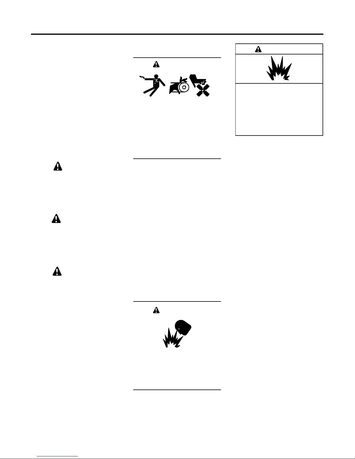
This manual has severaltypesofsafety
precautions and instructions: Danger,
Warning, Caution, and Notice.
DANGER
Danger indicates the presence of a
hazard that will cause severe
personal injury,death,orsubstantial
property damage.
WARNING
Warning indicates the presence of a
hazard that can cause severe
personal injury,death,or substantial
property damage.
CAUTION
Caution indicates the presence of a
hazard that will or can cause minor
personal injury or property damage.
NOTICE
Notice communicates installation,
operation, or maintenance information
that is safety related but not hazard
related.
Safety decals affixed to the equipment
in prominent places alert the operator
or service technician to potential
hazards and explain how to act safely.
The decals are shown throughout this
publication to improve operator
recognition. Replace missing or
damaged decals.
Accidental Starting
WARNING
Accidental starting.
Can cause severe injury or death.
Disconnect the battery cables before
working on the generator set.
Remove the negative (--) lead first
when disconnecting the battery.
Reconnect the negative (--) lead last
when reconnecting the battery.
Disabling the generator set.
Accidental starting can cause
severe injury or death. Before
working on the generator set or
connected equipment, disable the
generator set as follows: (1) Move the
generator set master switch to the OFF
position. (2) Disconnect the power to
the battery charger. (3) Remove the
battery cables, negative (--) lead first.
Reconnect the negative (--) lead last
when reconnecting the battery. Follow
these precautions to prevent starting of
the generator set by an automatic
transfer switch, remote start/stop
switch, or engine start command from a
remote computer.
Battery
WARNING
Sulfuric acid in batteries.
Can cause severe injury or death.
Wear protective goggles and
clothing. Battery acid may cause
blindness and burn skin.
WARNING
Explosion.
Can cause severe injury or death.
Relays in the battery charger
cause arcs or sparks.
Locate the battery in a well-ventilated
area. Isolatethe battery charger from
explosive fumes.
Battery electrolyte is a diluted
sulfuric acid. Battery acid can cause
severe injury or death. Battery acid
can cause blindness and burn skin.
Always wear splashproof safety
goggles, rubber gloves, and boots
when servicing the battery. Do not
open a sealed battery or mutilate the
battery case. Ifbattery acid splashes in
the eyes or on the skin, immediately
flush the affected area for 15 minutes
with large quantities of clean water.
Seek immediate medical aid in the case
of eye contact. Never add acid to a
battery after placing the battery in
service, as this may result in hazardous
spattering of battery acid.
Battery acid cleanup. Battery acid
can cause severe injury or death.
Battery acid is electrically conductive
and corrosive. Add 500 g (1 lb.) of
bicarbonate of soda (baking soda) to a
containerwith4L(1gal.)ofwaterand
mix the neutralizing solution. Pour the
neutralizing solution on the spilled
battery acid and continue to add the
neutralizing solution to the spilled
battery acid until all evidence of a
chemical reaction (foaming) has
ceased. Flush the resulting liquid with
water and dry the area.
TP-6049 9/02 ISafety Precautions and Instructions
Page 6

Battery gases. Explosion can cause
severe injury or death. Battery gases
can cause an explosion. Do not smoke
or permit flames or sparks to occur near
a battery at any time, particularly when
it is charging. Do not dispose of a
battery in a fire. To prevent burns and
sparks that could cause an explosion,
avoid touching the battery terminals
with tools or other metal objects.
Remove all jewelry before servicing the
equipment. Discharge static electricity
from your body before touching
batteries by first touching a grounded
metal surface away from the battery. To
avoid sparks, do not disturb the battery
charger connections while the battery
is charging. Always turn the battery
charger off before disconnecting the
battery connections. Ventilate the
compartments containing batteries to
prevent accumulation of explosive
gases.
Battery short circuits. Explosion
can cause severe injury or death.
Short circuits can cause bodily injury
and/or equipment damage.
Disconnect the battery before
generator set installation or
maintenance. Remove all jewelry
before servicing the equipment. Use
tools with insulated handles. Remove
the negative (--) lead first when
disconnecting the battery. Reconnect
the negative (--) lead last when
reconnecting the battery. Never
connect the negative (--) battery cable
to the positive (+) connection terminal
of the starter solenoid. Do not test the
battery condition by shorting the
terminals together.
Engine Backfire/Flash
Fire
WARNING
Fire.
Can cause severe injury or death.
Do not smoke or permit flames or
sparks near fuels or the fuel system.
Servicing the air cleaner. A sudden
backfire can cause severe injury or
death. Do not operate the generator
set with the air cleaner removed.
Exhaust System
WARNING
Carbon monoxide.
Can cause severe nausea,
fainting, or death.
The exhaust system must be
leakproof and routinely inspected.
Generator set operation. Carbon
monoxide can cause severe nausea,
fainting, or death. Carbon monoxide
is an odorless, colorless, tasteless,
nonirritating gas that can cause death if
inhaled for even a short time. Avoid
breathing exhaust fumes when working
on or near the generator set. Never
operate the generator set inside a
building unless the exhaust gas is
piped safely outside. Never operate
the generator set where exhaust gas
could accumulate and seep back inside
a potentially occupied building.
Carbon monoxide symptoms.
Carbon monoxide can cause severe
nausea, fainting, or death. Carbon
monoxide is a poisonous gas present in
exhaust gases. Carbon monoxide
poisoning symptoms include but are
not limited to the following:
D Light-headedness, dizziness
D Physical fatigue, weakness in
joints and muscles
D Sleepiness, mental fatigue,
inability to concentrate
or speak clearly, blurred vision
D Stomachache, vomiting, nausea
If experiencing any of these symptoms
and carbon monoxide poisoning is
possible, seek fresh air immediately
and remain active. Do not sit, lie down,
or fall asleep. Alert others to the
possibility of carbon monoxide
poisoning. Seek medical attention if
the condition of affected persons does
not improve within minutes of breathing
fresh air.
Fuel System
WARNING
Explosive fuel vapors.
Can cause severe injury or death.
Use extreme care when handling,
storing, and using fuels.
The fuel system. Explosive fuel
vapors can cause severe injury or
death. Vaporized fuels are highly
explosive. Use extreme care when
handling and storing fuels. Store fuels
inawell-ventilatedareaawayfrom
spark-producing equipment and out of
the reach of children. Never add fuel to
the tank while the engine is running
because spilled fuel may ignite on
contact with hot parts or from sparks.
Do not smoke or permit flames or
sparks to occur near sources of spilled
fuel or fuel vapors. Keep the fuel lines
and connections tight and in good
condition. Do not replace flexible fuel
lines with rigid lines. Use flexible
sections to avoid fuel line breakage
caused by vibration. Donot operate the
generator set in the presence of fuel
leaks, fuel accumulation, or sparks.
Repair fuel systems before resuming
generator set operation.
Explosive fuel vapors can cause
severe injury or death. Tak e
additional precautions when using the
following fuels:
Propane (LP)—Adequate ventilation
is mandatory. Because propane is
heavier than air, install propane gas
detectors low in a room. Inspect the
detectors per the manufacturer’s
instructions.
Natural Gas—Adequate ventilation is
mandatory. Because natural gas rises,
install natural gas detectors high in a
room. Inspect the detectors per the
manufacturer’s instructions.
TP-6049 9/02II Safety Precautions and Instructions
Page 7
Gas fuel leaks. Explosive fuel
vapors can cause severe injury or
death. Fuel leakage can cause an
explosion. Check the LP vapor gas or
natural gas fuel system for leakage by
using a soap and water solution with
the fuel system test pressurized to
6--8 ounces per square inch
(10--14 inches water column). Do not
use a soap solution containing either
ammonia or chlorine because both
prevent bubble formation. A successful
test depends on the ability of the
solution to bubble.
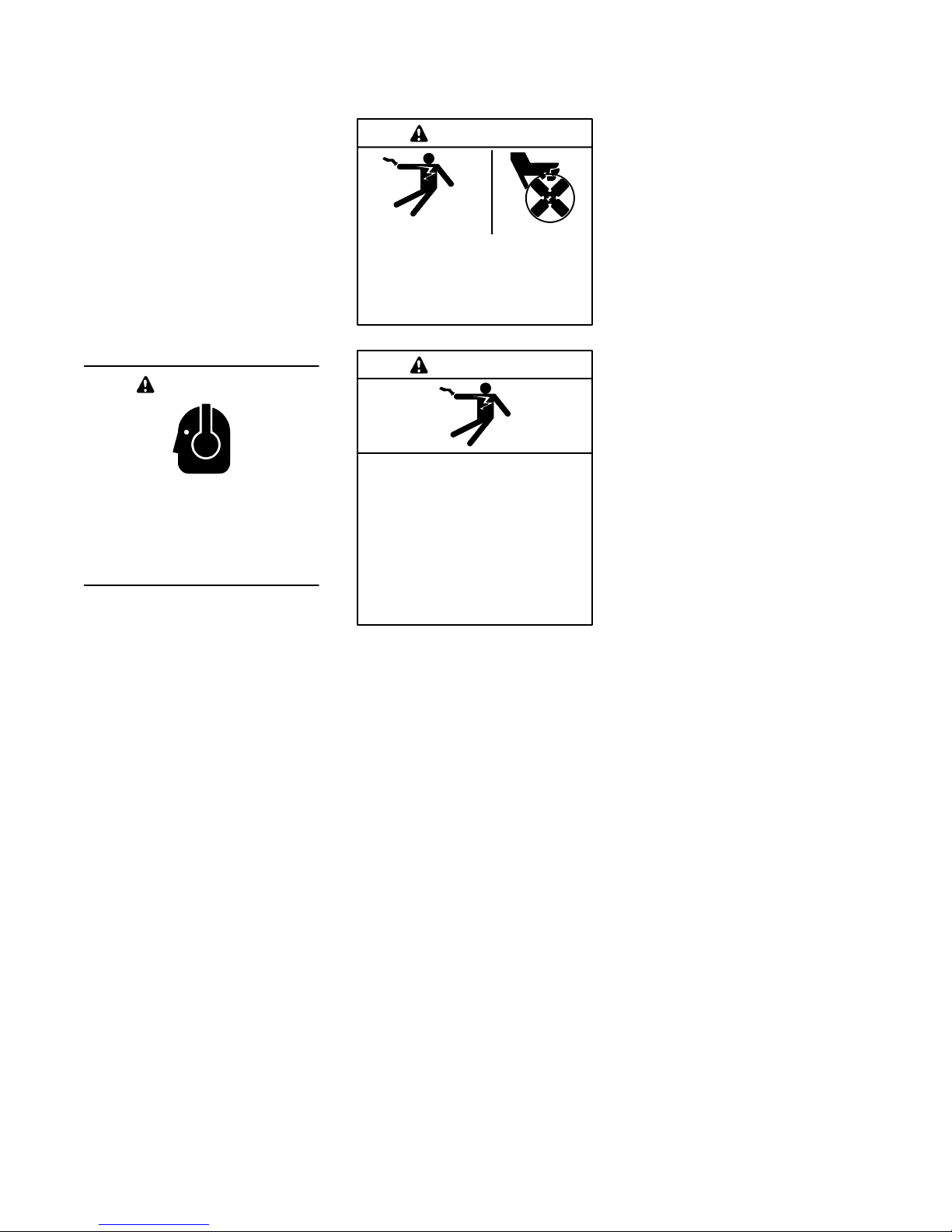
Hazardous Noise
CAUTION
Hazardous noise.
Can cause hearing loss.
Never operate the generator set
without a muffler or with a faulty
exhaust system.
Engine noise. Hazardous noise can
cause hearing loss. Generator sets
not equipped with sound enclosures
can produce noise levels greater than
105 dBA. Prolonged exposure to noise
levels greater than 85 dBA can cause
permanent hearing loss. Wear hearing
protection when near an operating
generator set.
Hazardous Voltage/
Electrical Shock
WARNING
Hazardous voltage.
Can cause severe injury or death.
Operate the generator set only when
all guards and electrical enclosures
areinplace.
WARNING
Hazardous voltage.
Backfeed to the utility system can
cause property damage, severe
injury, or death.
If the generator set is used for
standby power, install an automatic
transfer switch to prevent inadvertent
interconnection of standby and
normal sources of supply.
Grounding electrical equipment.
Hazardous voltage can cause
severe injury or death. Electrocution
is possible whenever electricity is
present. Open the main circuit
breakers of all power sources before
servicing the equipment. Configure the
installation to electrically ground the
generator set, transfer switch, and
related equipment and electrical
circuits to comply with applicable codes
and standards. Never contact
electrical leads or appliances when
standing in water or on wet ground
because these conditions increase the
risk of electrocution.
High voltage test. Hazardous
voltage can cause severe injury or
death. Follow the instructions of the
test equipment manufacturer when
performing high-voltage tests on the
rotor or stator. An improper test
procedure can damage equipment or
lead to generator set failure.
Moving rotor.
Installing the battery charger.
Hazardous voltage can cause
severe injury or death. An
ungrounded battery charger may
cause electrical shock. Connect the
battery charger enclosure to the ground
of a permanent wiring system. As an
alternative, install an equipment
grounding conductor with circuit
conductors and connect it to the
equipment grounding terminal or the
lead on the battery charger. Install the
battery charger as prescribed in the
equipment manual. Install the battery
charger in compliance with local codes
and ordinances.
Connecting the battery and the
battery charger. Hazardous voltage
can cause severe injury or death.
Reconnect the battery correctly,
positive to positive and negative to
negative, to avoid electrical shock and
damage to the battery charger and
battery(ies). Have a qualified
electrician install the battery(ies).
Short circuits. Hazardous
voltage/current can cause severe
injury or death. Short circuits can
cause bodily injury and/or equipment
damage. Do not contact electrical
connections with tools or jewelry while
making adjustments or repairs.
Remove all jewelry before servicing the
equipment.
Testing the voltage regulator.
Hazardous voltage can cause
severe injury or death. High voltage
is present at the voltage regulator heat
sink. To prevent electrical shock do not
touch the voltage regulator heat sink
when testing the voltage regulator.
(PowerBoostt, PowerBoostt III, and
PowerBoostt V voltage regulator
models only)
Electrical backfeed to the utility.
Hazardous backfeed voltage can
cause severe injury or death. Install
a transfer switch in standby power
installations to prevent the connection
of standby and other sources of power.
Electrical backfeed into a utility
electrical system can cause severe
injury or death to utility personnel
working on power lines.
TP-6049 9/02 IIISafety Precautions and Instructions
Page 8

Heavy Equipment
Moving Parts
Notice
WARNING
Unbalanced weight.
Improper lifting can cause severe
injury or death and equipment
damage.
Do not use lifting eyes.
Lift the generator set using lifting bars
inserted through the lifting holes on
the skid.
Hot Parts
WARNING
Hot engine and exhaust system.
Can cause severe injury or death.
Do not work on the generator set until
it cools.
Servicing the generator. Hot parts
can cause severe injury or death.
Avoid touching the generator set field
or exciter armature. When shorted, the
generator set field and exciter armature
become hot enough to cause severe
burns.
Servicing the exhaust system. Hot
parts can cause severe injury or
death. Do not touch hot engine parts.
The engine and exhaust system
components become extremely hot
during operation.
WARNING
Hazardous voltage.
Can cause severe injury or death.
Operate the generator set only when
all guards and electrical enclosures
areinplace.
Moving rotor.
WARNING
Rotating parts.
Can cause severe injury or death.
Operate the generator set only when
all guards, screens, and covers are in
place.
Tightening the hardware. Flying
projectiles can cause severe injury
or death. Loose hardware can cause
the hardware or pulley to release from
the generator set engine and can cause
personal injury. Retorque all
crankshaft and rotor hardware after
servicing. Do not loosen the crankshaft
hardware or rotor thrubolt when making
adjustments or servicing the generator
set. Rotate the crankshaft manually in
a clockwise direction only. Turning the
crankshaft bolt or rotor thrubolt
counterclockwise can loosen the
hardware.
Servicing the generator set when it
is operating. Exposed moving parts
can cause severe injury or death.
Keep hands, feet, hair, clothing, and
test leads away from the belts and
pulleys when the generator set is
running. Replace guards, screens, and
covers before operating the generator
set.
NOTICE
This generator set has been
rewired from its nameplate voltage
to
246242
NOTICE
Voltage reconnection. Affix a notice
to the generator set after reconnecting
the set to a voltage different from the
voltage on the nameplate. Order
voltage reconnection decal 246242
from an authorized service
distributor/dealer.
NOTICE
Hardware damage. The engine and
generator set may use both American
Standard and metric hardware. Use
the correct size tools to prevent
rounding of the bolt heads and nuts.
NOTICE
When replacing hardware, do not
substitute with inferior grade
hardware. Screws and nuts are
available in different hardness ratings.
To indicate hardness, American
Standard hardware uses a series of
markings, and metric hardware uses a
numeric system. Check the markings
on the bolt heads and nuts for
identification.
NOTICE
Canadian installations only.For
standby service connect the output of
the generator set to a suitably rated
transfer switch in accordance with
Canadian Electrical Code, Part 1.
TP-6049 9/02IV Safety Precautions and Instructions
Page 9
Introduction
This manual provides operation and installation
instructions for model 8.5RMY and 11RMY generator
sets equipped with sound enclosures. This manual
covers both single-fuel systems and multi-fuel systems.
To identify the generator set’s fuel system, see Section
1.5, Service Views, and Section 6.7, Fuel Systems.
Information in this publication represents data available
at the time of print. The manufacturer may provide this
manual for models not listed on the front cover. Kohler
Co. reserves the right to change this publication and the
products represented without notice and without any
obligation or liability whatsoever.
Read this manual and carefully follow all procedures
and safety precautions to ensure proper equipment
operation and to avoid bodily injury. Read and follow the
Safety Precautions and Instructions section at the
beginning of this manual. Keep this manual with the
equipment for future reference.
The equipment service requirements are very important
to safe and efficient operation. Inspect the parts often
and perform required service at the prescribed intervals.
Obtain service from an authorized service distributor/
dealer to keep equipment in top condition.
EPA and California Emission
Certification
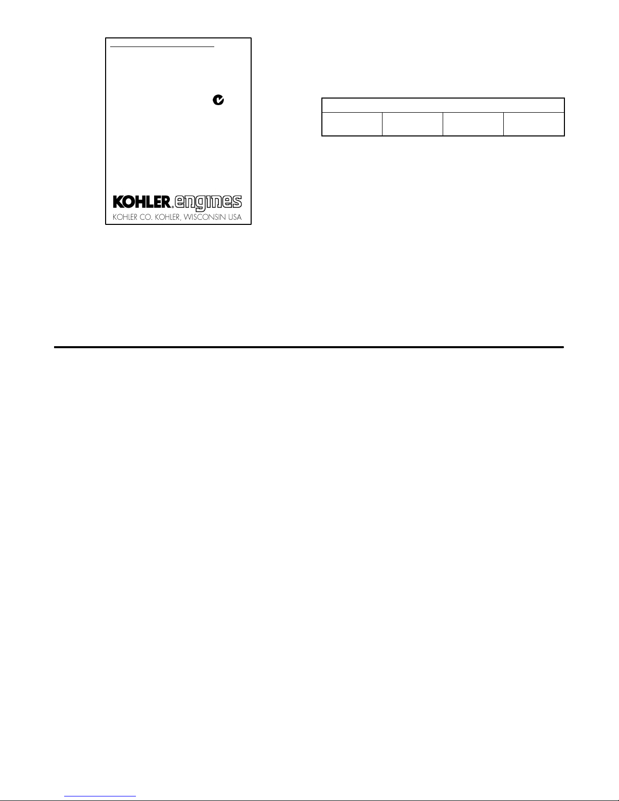
An engine or generator set with one of the following
identification labels is certified to meet Small Off-Road
Engine (SORE) emission standards for EPA/CARB.
*
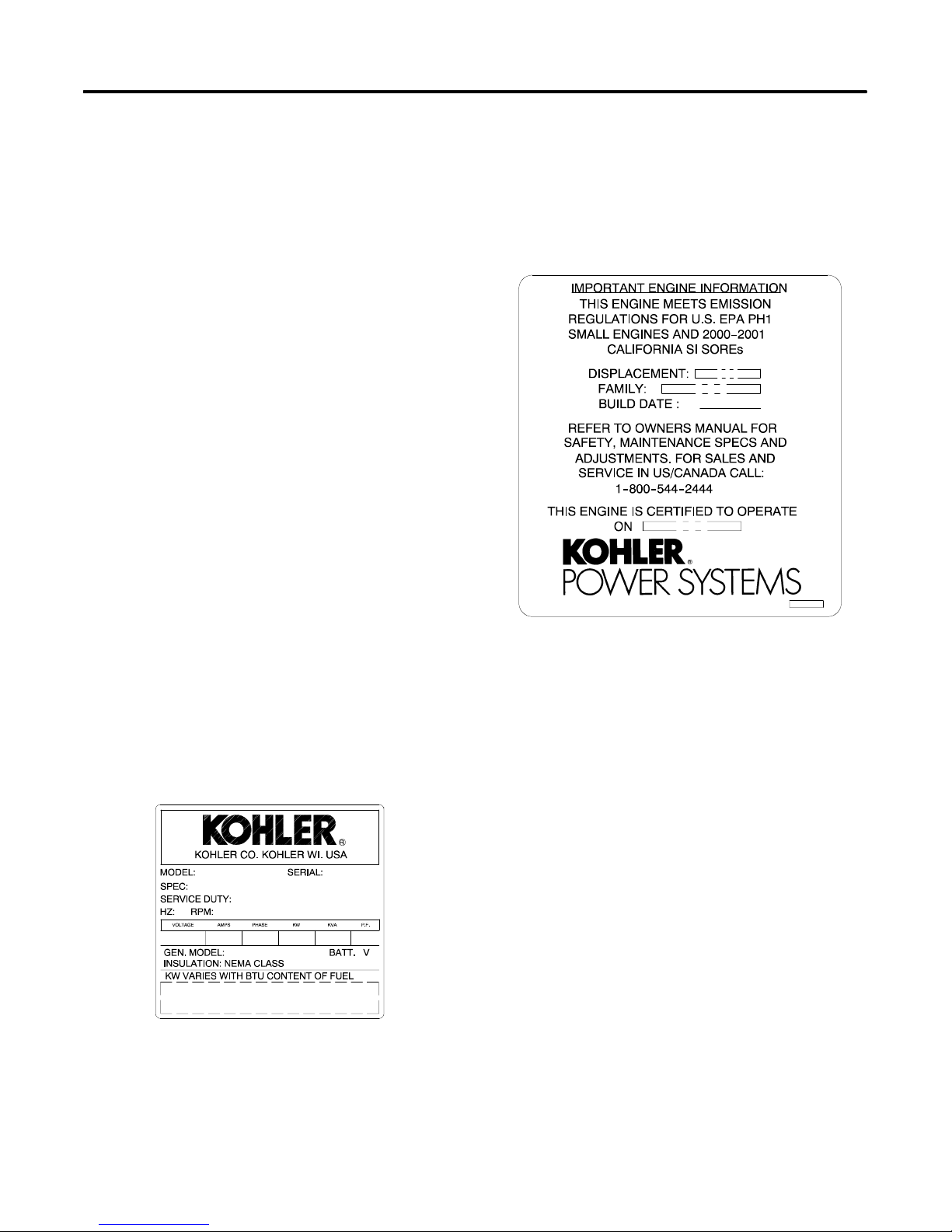
Nameplate
The following illustration shows a typical generator set
nameplate. Copy the model, serial, and specification
numbers from the nameplate into the spaces provided in
the product information section on the inside front cover
of this manual. See Section 1.5, Service Views, for the
nameplate location.
* Spark-Ignited Small Off-Road Engines
This engine/generator is certified to operate using
natural gas or propane fuel.
This engine is certified with engine modifications made
by the generator set manufacturer.
TP-6049 9/02 iIntroduction
Page 10
IMPORTANT ENGINE INFORMATION
THIS ENGINE MEETS U.S. EPA PHASE 1 AND
CALIFORNIA 2006 AND LATER EMISSION
CONTROL REGULATIONS FOR SI SORE
FAMILY
DISPL (CC)
MODEL NO.
SPEC. NO.
SERIAL NO.
EMISSION COMPLIANCE PERIOD:
EPA: CARB: EXTENDED
THIS ENGINE IS CERTIFIED TO OPERATE ON:
PROPANE / NATURAL GAS
REFER TO OWNER’S MANUAL FOR SAFETY,
MAINTENANCE SPECS AND ADJUSTMENTS.
FOR SALES AND SERVICE IN US/CANADA,
CALL:
1--800 --544--2444
WWW.KOHLERENGINES.COM
N11236
The Emission Compliance Period referred to on the
Emission Control or Air Index label indicates the number
of operating hours for which the engine has been shown
Service Assistance
to meet CARB emission requirements. The following
table provides the engine compliance period (in hours)
associated with the category descriptor found on the
certification label.
Emission Compliance Period (hours)
CARB
Moderate,
125
Intermediate,
250
Extended,
500
Refer to the certification label for engine displacement.
The exhaust emission control system for the 8.5RMY
and 11RMY (CH25) is EM.
Look for the identification label shown above to
determine whether generator sets with single-fuel
systems are emission-certified. All model 8.5RMY and
11RMY generator sets with multi-fuel systems are
emission-certified and include one of the identification
labels shown above.
For professional advice on generator power
requirements and conscientious service, please contact
your nearest Kohler distributor or dealer.
D Consult the Yellow Pages under the heading
Generators—Electric
D Visit the Kohler Power Systems website at
KohlerPowerSystems.com
D Look at the labels and stickers on your Kohler product
or review the appropriate literature or documents
included with the product
D Call toll free in the US and Canada 1-800-544-2444
D Outside the US and Canada, call the nearest regional
office
Africa, Europe, Middle East
London Regional Office
Langley, Slough, England
Phone: (44) 1753-580-771
Fax: (44) 1753-580-036
Asia Pacific
Power Systems Asia Pacific Regional Office
Singapore, Republic of Singapore
Phone: (65) 264-6422
Fax: (65) 264-6455
China
North China Regional Office, Beijing
Phone: (86) 10 6518 7950
(86) 10 6518 7951
(86) 10 6518 7952
Fax: (86) 10 6518 7955
East China Regional Office, Shanghai
Phone: (86) 21 6288 0500
Fax: (86) 21 6288 0550
India, Bangladesh, Sri Lanka
India Regional Office
Bangalore, India
Phone: (91) 80 3366208
(91) 80 3366231
Fax: (91) 80 3315972
Japan, Korea
North Asia Regional Office
Tokyo, Japan
Phone: (813) 3440-4515
Fax: (813) 3440-2727
Latin America
Latin America Regional Office
Lakeland, Florida, USA
Phone: (863) 619-7568
Fax: (863) 701-7131
X:in:008:001a
TP-6049 9/02ii Service Assistance
Page 11

Section 1 Features
1.1 Specifications
The generator set specification sheets provide specific
generator and engine information. Refer to the spec
sheet for data not supplied in this manual. Consult the
generator set service manual, engine operation manual,
and engine service manual for additional specifications.
Obtain copies of the latest spec sheets, manuals,
diagrams, and drawings from your local
distributor/dealer.
1.2 Generator
The generator uses Kohler’s unique PowerBoostt
voltage regulation system, which provides instant
response to load changes.
PowerBoostt ensures reliable motor starting and
consistent voltage levels. PowerBoostt utilizes a
voltage excitation system that employs a winding
independent of the main output windings to provide
excitation voltage.
1.3 Engine
The generator set has a four-cycle, twin cylinder,
air-cooled Kohlerr engine. The engine operates on
clean-burning natural gas or propane (LP) vapor.
Engine features include:
D Efficient overhead valve design and full pressure
lubrication for maximum power, torque, and reliability
under all operating conditions.
D Dependable, maintenance-free electronic ignition.
D Precision-formulated cast iron construction of parts
subjected to the most wear and tear.
D Field-convertible multi-fuel systems that allow fuel
changeover from natural gas to LP vapor (and
vice-versa) while maintaining CARB emission
certification.
1.4 Controller
The generator set has a Decision-Makert 1 relay
controller. For a specific description of the controller,
see Section 2, Operation. Controller features include
the following:
D Fault shutdowns
D Overcrank
D Overspeed
D Low oil pressure
D High engine temperature
D Running-time meter
D Switches and standard features
D Switch, run/reset-off/auto (engine start)
D Cranking, cyclic
D Line circuit breaker:
D 8.5RMY: 40 amps
D 11RMY: 50 amps
D Common fault lamp (on some controllers)
TP-6049 9/02 1Section 1 Features
Page 12
1.5 Service Views
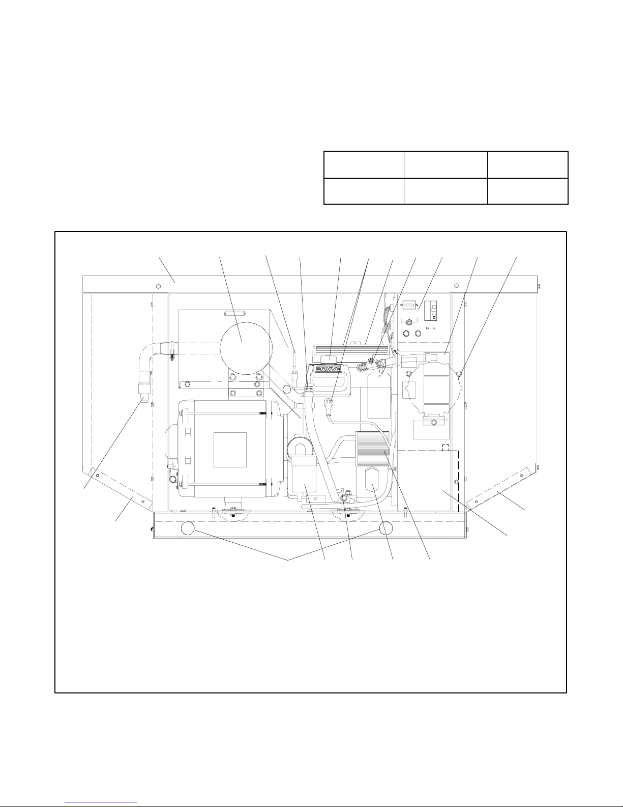
This section includes two generator set service views.
See Figure 1-1 and the descriptions below to determine
which service view applies to your generator set.
Figure 1-2 shows single-fuel generator sets, which can
be identified in two ways:
D Single-fuel model specification numbers begin with
PA-. See the generator set nameplate for the spec
number.
D Single-fuel models have the fuel valve shown in
Figure1-2,item8.
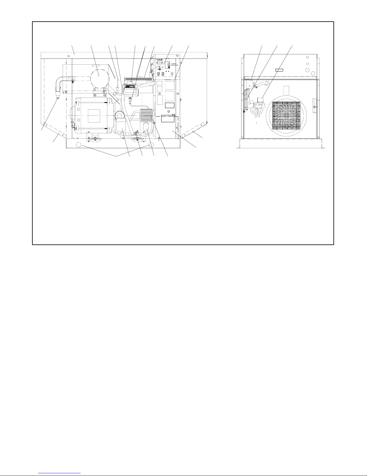
Figure 1-3 Shows multi-fuel generator sets, which can
be identified in two ways:
D Multi-fuel model specification numbers begin with
GM. See the generator set nameplate for the spec
number.
D Multi-fuel models have the multi-fuel block shown in
Figure 1-3, item 10.
Spec Number
Format
Fuel System Service View
PA-xxxxxx Single-fuel Figure 1-2
GMxxxxx Multi-fuel Figure 1-3
Figure 1-1 Service View Identification
19
12
123 679 11
~
5
84 10
ON
OFF
RESET/
AUTOOFF
RUN
F210 AMP
F110 AMP
TYPEABCTYPEABC
12
13
1. Generator set sound enclosure
2. Muffler
3. Oil check
4. Oil drain hose
5. Oil fill
6. Spark plugs
7. Air cleaner
8. Fuel valve (Do not adjust on emission-certifed models.)
9. Controller
10. Nameplate
Figure 1-2 Generator Set Service View, Single-Fuel Systems (spec numbers PA-)
18
1617
11. Gas regulator assembly
12. Rodent screens
13. Engine starting battery location
14. Engine oil cooler
15. Engine battery charge regulator
16. Oil drain valve
17. Oil filter
18. Rodent plugs
19. Spark arrestor
1415
P-358000-C
TP-6049 9/022 Section 1 Features
Page 13
20
13
123 678 11
4 9 12
5
10
13
14
19
1718
1516
GM24829A-A
1. Generator set sound enclosure
2. Muffler
3. Oil check
4. Oil drain hose
5. Oil fill
6. Spark plugs
7. Air cleaner
8. Controller
9. Nameplate
10. Multi-fuel block
11. Gas regulator assembly
12. Fuel solenoid valve
13. Rodent screens
14. Engine starting battery location
15. Engine oil cooler
16. Engine battery charge regulator
17. Oil drain valve
18. Oil filter
19. Rodent plugs
20. Spark arrestor
Figure 1-3 Generator Set Service View, Multi-Fuel Systems (spec numbers GMxxxxx)
TP-6049 9/02 3Section 1 Features
Page 14

Notes
TP-6049 9/024 Section 1 Features
Page 15

Section 2 Operation
2.1 Prestart Checklist
To ensure continued satisfactory operation, perform the
following checks or inspections before or at each
startup, as designated, and at the intervals specified in
the service schedule. In addition, some checks require
verification after the unit starts.
Air Cleaner. Check for a clean and installed air cleaner
element to prevent unfiltered air from entering the
engine.
Air Inlets. Check for clean and unobstructed air inlets.
Battery. Check for tight battery connections. Consult
the battery manufacturer’s instructions regarding
battery care and maintenance.
Exhaust System. Check for exhaust leaks and
blockages. Check the muffler and piping condition and
check for tight exhaust system connections.
Inspect the exhaust system components (exhaust
manifold, exhaust line, flexible exhaust, clamps, muffler,
and outlet pipe) for cracks, leaks, and corrosion.
D Check for corroded or broken metal parts and replace
them as needed.
D Check for loose, corroded, or missing clamps and
hangers. Tighten or replace the exhaust clamps
and/or hangers as needed.
D Check that the exhaust outlet is unobstructed.
D Visually inspect for exhaust leaks (blowby). Check
for carbon or soot residue on exhaust components.
Carbon and soot residue indicates an exhaust leak.
Seal leaks as needed.
Oil Level. Maintain the oil level at or near, not over, the
full mark on the dipstick.
Operating Area. Check for obstructions that could
block the flow of cooling air. Keep the air intake area
clean. Do not leave rags, tools, or debris on or near the
generator set.
x:op:001:002
2.2 Exercising the Generator Set
Operate the generator set under load once each week
for one hour. If the generator set does not have a
programmed exercise mode or an automatic transfer
switch (ATS) with an exercise option, exercise the unit in
the presence of an operator.
During the exercise period apply a minimum of 35% load
based on the nameplate standby rating.
The operator should perform all of the prestart checks
before starting the exercise procedure. Start the
generator set according to the starting procedure in the
controller section of this manual. While the generator
set is operating, listen for a smooth-running engine and
visually inspect the generator set for fluid or exhaust
leaks. Check the air inlets and outlets and remove any
items restricting the air flow.
TP-6049 9/02 5Section 2 Operation
Page 16
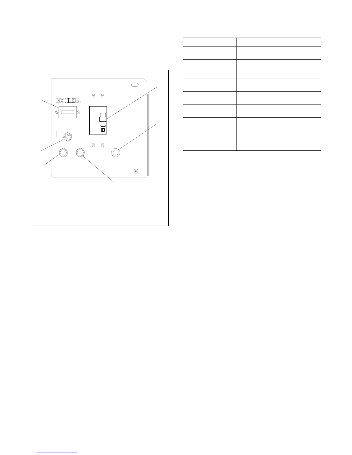
2.3 Decision-Maker 1 Controller
Operation
For identification of the Decision-Makert 1 controller’s
indicators and controls and their functions, refer to
Figure 2-1.
2
1
RUN
6
F1 10 AMP
5
1. Hourmeter
2. AC circuit breaker
3. Fault lamp
4. Voltage regulator fuse
5. 10-amp controller fuse
6. Generator set master switch
Figure 2-1 Decision-Makert 1 Controller (with Fault
2.3.1 Controls and Indicators
RESET/
AUTOOFF
F2 10 AMP
TYPE ABCTYPE ABC
Lamp)
R
ON
OFF
FAULT
3
GM10615
4
Note: The controller provides up to 30 seconds of cyclic
cranking before the overcrank shutdown occurs.
Name Description
Generator set master
switch
Hourmeter Hourmeter records the generator set
Voltage regulator fuse,
10-amp
Controller fuse, 10-amp Fuse protects the controller circuitry
AC circuit breaker Circuit breaker trips when a fault is
Fault lamp Lamp lights when a fault shuts the
Switch functions as the controller reset
and generator set operation switch.
total operating hours for reference in
maintenance scheduling.
Fuse protects the voltage regulator
circuitry.
from short circuits and overloads.
detected in the AC output circuit.
generator set down and remains lit until
the generator set master switch is
moved to the OFF/RESET position.
See Section 2.3.4 for fault shutdown
information.
Figure 2-2 Decision-Makert 1 Controls and
Indicators
2.3.3 Stopping the Generator Set
The following procedures describe the actions required
to stop the generator set.
Automatic Stopping
1. The ATS or other device disconnects the load from
the generator set.
2. The generator set continues to run for a preset
cooldown time if the ATS is equipped with an
engine cooldown time delay.
The table in Figure 2-2 describes the controls and
indicators located on the controller.
2.3.2 Starting the Generator Set
The following procedures describe the actions required
to start the generator set.
Local Starting. Move the generator set to the RUN
position to immediately start the generator set.
Auto (Automatic) Starting. Move the generator set
master switch to the AUTO position to allow startup by
the ATS or the remote start/stop switch (connected to
controller terminals TB1-3 and TB1-4).
3. The ATS or other device opens the connection
between controller terminals TB1-3 and TB1-4.
The generator set shuts down if the generator set
master switch is in the AUTO position.
Local Stopping
1. Cooldown. Run the generator set at no load for at
least 2 minutes to ensure adequate engine
cooldown.
2. Stopping. Move the generator set master switch
to the OFF/RESET position. The engine stops.
TP-6049 9/026 Section 2 Operation
Page 17

2.3.4 Fault Shutdowns
The generator set shuts down automatically under the
fault conditions listed in Figure 2-3 and cannot be
restarted until the fault condition is corrected. The
generator set shutdown switches automatically reset
when the problem is corrected. The high engine
temperature switch automatically resets when the
generator set cools.
After a fault shutdown leave the generator set master
switch in the RESET/OFF position for a couple of
seconds before attempting to restart the generator set.
3. Start the generator set by moving the generator set
master switch to RESET/OFF and then to RUN.
4. Verify that the cause of the shutdown has been
corrected by test operating the generator set.
5. Reconnect the generator set to the load using the
line circuit breaker or ATS.
6. Move the generator set master switch to the AUTO
position for startup by remote transfer switch or
remote start/stop switch.
2.4 Circuit Protection
Fault Description
High engine
temperature
Low oil pressure Shutdown occurs 5 seconds after the fault.
Overcrank Shutdown occurs after 30 seconds of cyclic
Overspeed Shutdown occurs immediately when the
Shutdown occurs 5 seconds after the fault.
The high engine temperature shutdown does
not function during the first 5 seconds after
startup.
The low oil pressure shutdown does not
function during the first 5 seconds after
startup.
Note: The low oil pressure shutdown does
not protect against low oil level. Check the oil
level at the engine.
cranking. The factory sets the circuit board
for three starting attempts of 8 seconds each
(crank 8 seconds, wait 3 seconds, crank 8
seconds, wait 3 seconds, crank 8 seconds).
The generator set also shuts down if the
output line voltage is lost. Shuts down 1
second after the fault is detected.
governed frequency on 50 and 60 Hz models
exceeds 70 Hz.
Figure 2-3 Fault Shutdowns
2.3.5 Resetting the Controller after a
Fault Shutdown
Use the following procedure to restart the generator set
after a fault shutdown.
See Figure 2-1 for the line circuit breaker, controller
fuse, and voltage regulator fuse locations.
Note: If the generator set circuit breaker trips or the
fuses blow repeatedly, see Section 4,
Troubleshooting, for possible causes.
Line Circuit Breaker. A line circuit breaker interrupts
the generator output in the event of a fault in the wiring
between the generator and the load. See Figure 2-4 for
the circuit breaker ratings. If the circuit breaker trips,
reduce the load and switch the breaker back to the ON
position. With the breaker in the OFF position the
generator set runs but the generator output is
disconnected from the load.
Circuit Breaker
Model
8.5RMY 40
11R M Y 50
Rating, Amps
Figure 2-4 Line Circuit Breakers
Controller Fuse. A replaceable 10-amp fuse protects
the controller circuitry. If the generator set does not
crank, check the battery and battery connections and
then check the controller fuse. Replace the fuse if it is
blown.
1. Disconnect the generator set from the load using
the line circuit breaker or ATS. See the safety
precautions at the beginning of this section before
proceeding.
2. Correct the cause of the fault shutdown. See the
safety precautions at the beginning of this section
before proceeding.
TP-6049 9/02 7Section 2 Operation
Voltage Regulator Fuse. A replaceable 10-amp fuse
protects the voltage regulator circuitry. The generator
set shuts down if the fuse blows. When the operator
starts a generator set with a blown voltage regulator
fuse, the generator set typically starts and then shuts
down in 8 seconds.
x:op:007:001
Page 18

Notes
TP-6049 9/028 Section 2 Operation
Page 19
Section 3 Scheduled Maintenance
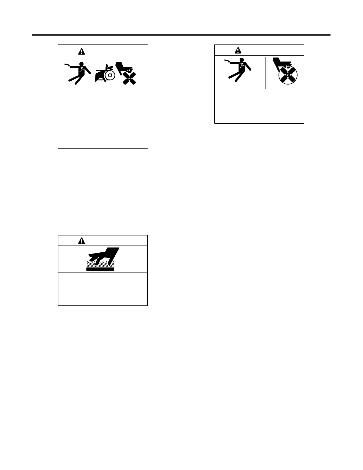
WARNING
Accidental starting.
Can cause severe injury or death.
Disconnect the battery cables before
working on the generator set.
Remove the negative (--) lead first
when disconnecting the battery.
Reconnect the negative (--) lead last
when reconnecting the battery.
Disabling the generator set. Accidental starting can
cause severe injury or death. Before working on the
generator set or connected equipment, disable the generator
set as follows: (1) Move the generator set master switch to the
OFF position. (2) Disconnect the power to the battery charger.
(3) Remove the battery cables, negative (--) lead first.
Reconnect the negative (--) lead last when reconnecting the
battery. Follow these precautions to prevent starting of the
generator set by an automatic transfer switch, remote
start/stop switch, or engine start command from a remote
computer.
WARNING
WARNING
Hazardous voltage.
Can cause severe injury or death.
Operate the generator set only when
all guards and electrical enclosures
areinplace.
Servicing the generator set when it is operating. Exposed
moving parts can cause severe injury or death. Keep
hands, feet, hair, clothing, and test leads away from the belts
and pulleys when the generator set is running. Replace
guards, screens, and covers before operating the generator
set.
Moving rotor.
3.1 Routine Maintenance
Refer to the service schedule following and the
hourmeter located on the generator set controller to
schedule routine maintenance. Have an authorized
distributor/ dealer perform all generator set service.
Perform maintenance on each item in the service
schedule at the designated interval for the life of the
generator set. Service units subject to extreme weather,
long operating hours, or dusty or dirty conditions more
frequently.
Hot engine and exhaust system.
Can cause severe injury or death.
Do not work on the generator set until it
cools.
3.2 Service Schedule
Perform the items listed in the following service
schedule at the designated intervals for the life of the
generator set. For example, an item serviced every
Servicing the exhaust system. Hot parts can cause
severe injury or death. Do not touch hot engine parts. The
engine and exhaust system components become extremely
hot during operation.
100 hours of operation or 3 months must also be
serviced after 200 hours or 6 months, 300 hours or
9 months and so on. Rough operation, lack of power,
and excessive oil use indicate serious generator set
problems. Have an authorized distributor/ dealer
perform all generator set service.
TP-6049 9/02 9Section 3 Scheduled Maintenance
Page 20
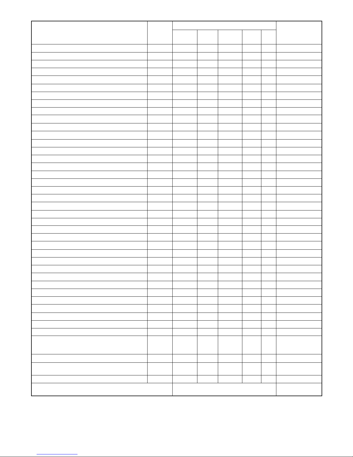
Procedure
Visually
Inspect
Check Change Clean Test
Frequency
System Component or Procedure
See
Section
Fuel
Flexible lines and connections X R Quarterly
Main tank supply level X Weekly
Fuel piping X Yearly
Lubrication
Oil level X X Daily or before use
Crankcase breather* X X Yearly or 500 hours
Change oil X Yearly or 100 hours
Replace filter* X Yearly or 200 hours
Cooling
Air ducts, louvers X X Yearly
Exhaust Line
Leakage X X Weekly
Insulation, fire hazards X Yearly
Hangers and supports X Yearly
DC Electrical System
Battery charger operation, charge rate (if equipped) X Monthly
Remove corrosion, clean and dry battery and rack X X Yearly
Clean and tighten battery terminals X X Yearly
Battery electrolyte level and specific gravity[
3.3
3.6
3.7
3.8
X Yearly
AC Electrical System
Visible wear or damage X Quarterly
Wire abrasions where subject to motion X X Six Months
Tighten control and power wiring connections X Yearly
Wire-cable insulation breakdown* X 3 Years or 500 hours
Engine And Mounting
Visible wear or damage X Weekly
Air cleaner service 3.5 R Yearly or 100 hours
Spark plugs 3.4 X Yearly or 300 hours
Remote Control System
Compartment condition X X Weekly
Remote control X Monthly
Run generator set X Weekly
Generator
Visible wear or damage 2.1 X Quarterly
Exercise generator set 2.2 X Monthly
Rotor and stator* X X Yearly
Measure and record resistance readings of
windings with insulation tester (Megger, with
SCR assembly or rectifier disconnected)
X 3 Years
General Condition of Equipment
Evidence of vibration, leakage, excessive noise,
temperature, or deterioration
Interior of sound shield housing X X Quarterly
* Consult your local distributor/dealer for parts or service.
[ Not necessary for maintenance-free batteries.
X X X Weekly
XAction
R Replace as necessary
Figure 3-1 Service Schedule
TP-6049 9/0210 Section 3 Scheduled Maintenance
Page 21

3.3 Lubrication System
3.3.4 Oil Change Procedure
See Section 3.2, Service Schedule, for oil change and
oil filter replacement intervals. See Section 1.5, Service
Views, for the oil drain, oil check, oil fill, and oil filter
locations.
3.3.1 Low Oil Pressure Shutdown
The low oil pressure shutdown feature protects the
engine against internal damage if the oil pressure drops
below 24.1 kPa ±13.8 kPa (3.5 psi ±1.5 psi) because of
oil pump failure or other malfunction. The shutdown
feature does not protect against damage caused by
operating with the oil level below the safe range; it is not
a low oil level shutdown. Check the oil level regularly,
and add oil as needed.
3.3.2 Oil Check
The generator set is shipped with oil. Before operating a
new generator set, check the engine oil in the
crankcase. See 1.5, Service Views. Verify that the oil
level is at the F mark on the dipstick. Add oil that has a
viscosity appropriate for the climate. See Section 3.3.3,
Engine Oil Recommendation, for engine oil
recommendations.
Drain the oil while it is still warm.
1. Drain the oil.
a. Place the generator set master switch in the
OFF position.
b. Disconnect the power to the battery charger, if
equipped.
c. Disconnect the generator set engine starting
battery, negative (--) lead first.
d. Remove the housing side panel.
e. Remove the oil drain hose from its retaining
clip. Remove the cap from the oil drain hose
and lower the hose into an oil collection
container.
f. Open the oil drain valve on the engine.
g. Allow time for the engine oil to drain completely.
h. Close the oil drain valve.
i. Replace the cap on the oil drain hose. Replace
theoildrainhoseinitsretainingclip.
Do not check the oil level when the generator set is
running. Shut down the generator set and wait several
minutes before checking the oil level.
3.3.3 Engine Oil Recommendation
Use API (American Petroleum Institute) Service Class
SG, SH, or SJ synthetic oil. Synthetic oil oxidizes and
thickens less than other oils and leaves the engine
intake valves and pistons cleaner. Select the viscosity
based on the air temperature at the time of operation.
SeeFigure3-2.
10W-30
5W-20, 5W-30
-- 2 0
°C°F-- 3 0
Temperature Range Expected Before Next Oil Change
-- 2 0
01020
-- 1 0
Figure 3-2 Engine Oil Selection
32 60 80 100
40
02040
30
2. Replace the oil filter.
a. Remove the oil filter by rotating it
counterclockwise with an oil filter wrench.
b. Clean the gasket sealing surface of the oil filter
adapter.
c. Apply a light coat of clean oil to the rubber seal
of the new oil filter.
d. Install the new oil filter following the instructions
provided with the filter.
Note: Dispose of all waste materials (engine
oil, fuel, filter, etc.) in an environmentally
safe manner.
3. Fill with oil.
a. Remove the oil fill cap and fill the engine to the F
mark on the dipstick. The engine oil capacity is
1.9 L (2.0 qt.). See Section 3.3.3, Engine Oil
Recommendation, for oil selection.
b. Reinstall the dipstick and the oil fill cap.
c. Check that the generator set master switch is in
the OFF position.
TP-6049 9/02 11Section 3 Scheduled Maintenance
Page 22
d. Reconnect the generator set engine starting
battery, negative (--) lead last.
e. Reconnect the power to the battery charger, if
equipped.
f. Start and run the generator set for a minute to
allow the oil pressure to reach the operating
range.
g. Stop the generator set, wait 1 minute, and then
recheck the oil level. Add oil to bring the level
up to the F mark on the dipstick.
4. Check for leaks.
a. Check for oil leaks.
b. Fix leaks and recheck the oil level.
c. Reinstall the housing side panel.
3.4 Spark Plugs
1--511
Figure 3-4 Adjusting the Spark Plug Gap
3.5 Air Cleaner Element and
Precleaner
The engine has a replaceable high-density paper air
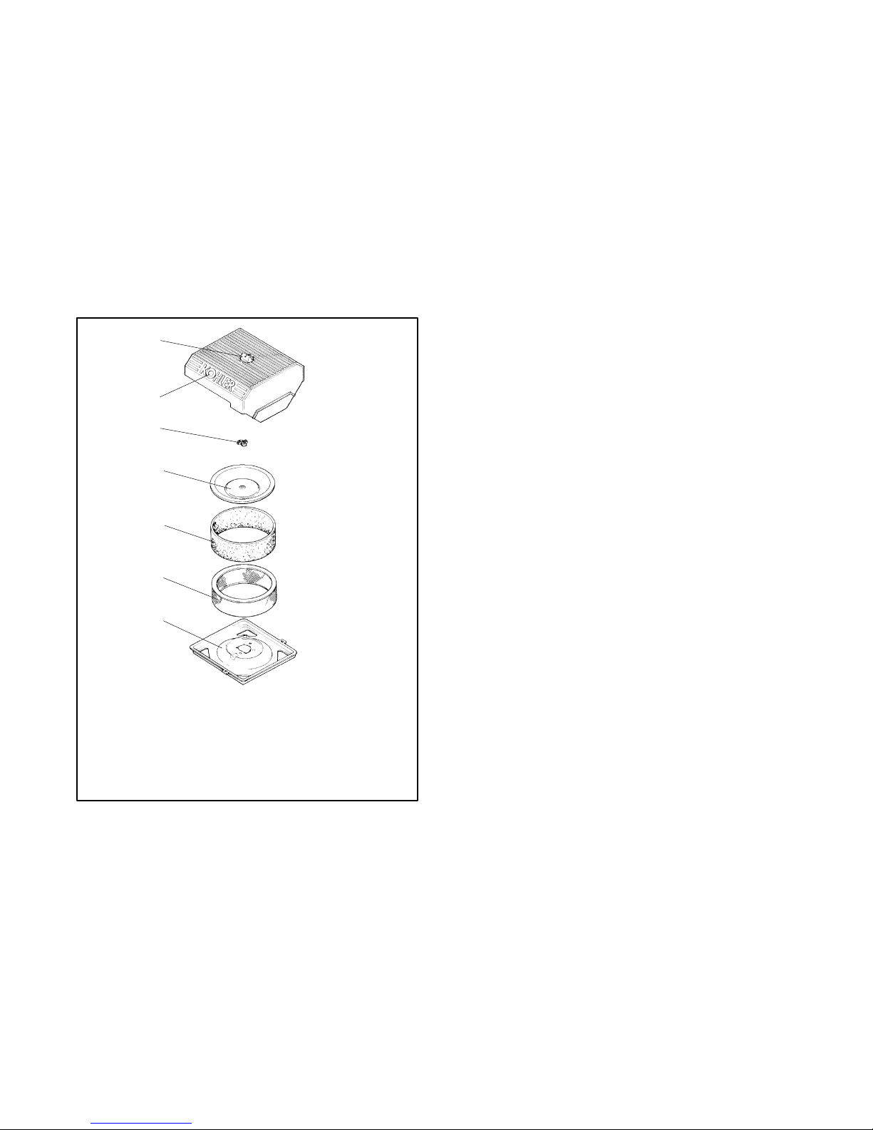
cleaner element with an oiled foam precleaner. See
Figure 3-5.
Check for a buildup of dirt and debris around the air
cleaner system. Keep this area clean.
Reset the spark plug gap or replace the plugs with new
plugs as necessary.
1. Clean the area around the base of the spark plug to
keep dirt and debris out of the engine.
2. Remove the spark plug and check its condition.
Replace the spark plug if it is worn or if its reuse is
questionable.
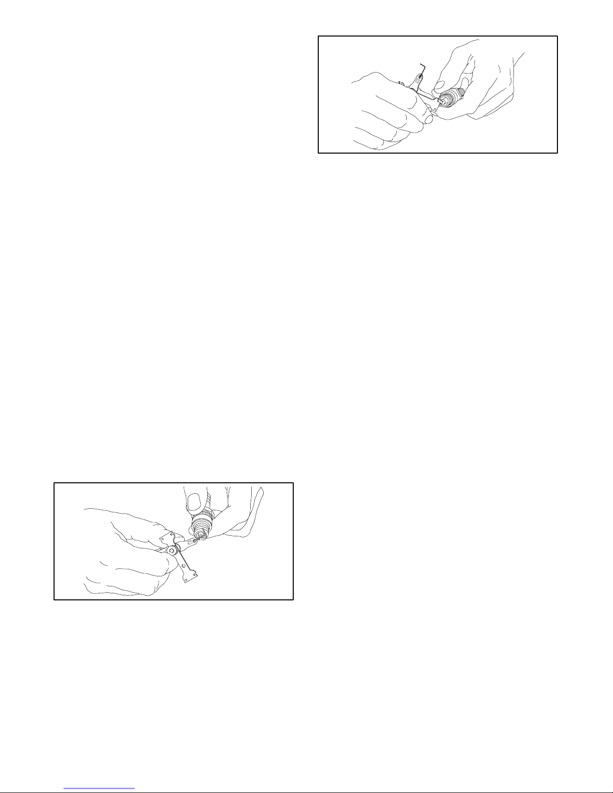
3. Check the spark plug gap using a wire feeler
gauge. Adjust the gap to 0.76 mm (0.030 in.) by
carefully bending the ground electrode. See
Figure 3-3 and Figure 3-4.
1--514
Figure 3-3 Checking the Spark Plug Gap
Note: Operating the engine with loose or damaged air
cleaner components could allow unfiltered air
into the engine causing premature wear and
failure.
3.5.1 Precleaner Service
Use the following procedure to wash and reoil the
precleaner as indicated in the service schedule. Wash
and reoil the precleaner more often under extremely
dusty or dirty conditions.
1. Place the generator set master switch in the
OFF/RESET position.
2. Disconnect the power to the battery charger, if
equipped.
3. Disconnect the battery, negative (--) lead first.
4. Loosen the cover retaining knob and remove the
cover. Remove the precleaner from the paper
element. Wash the precleaner in warm water with
detergent. Rinse the precleaner thoroughly until all
traces of detergent are eliminated. Squeeze out
TP-6049 9/0212 Section 3 Scheduled Maintenance
Page 23
excess water (do not wring). Allow the precleaner
to air dry.
5. Saturate the precleaner with new engine oil.
Squeeze out all of the excess oil.
6. Reinstall the precleaner over the paper element.
7. Reinstall the air cleaner cover. Secure the cover
with the cover retaining knob.
8. Reconnect the power to the battery charger, if
equipped.
9. Reconnect the generator set engine starting
battery, negative (--) lead last.
1
2
3
4
3.5.2 Paper Element Service
Use the following procedure to replace the paper
element at the intervals specified in the service
schedule. Replace the paper element more often under
extremely dusty or dirty conditions.
1. Place the generator set master switch in the
OFF/RESET position.
2. Disconnect the power to the battery charger, if
equipped.
3. Disconnect the generator set engine starting
battery, negative (--) lead first.
4. Loosen the cover retaining knob and remove the
cover.
5. Remove the element cover nut, element cover, and
the paper element with precleaner.
6. Remove the precleaner from the paper element.
Note: Do not wash the paper element or clean it
with pressurized air, as this will damage the
element.
5
6
7
1. Cover knob
2. Air cleaner cover
3. Element cover nut
4. Element cover
5. Foam precleaner
6. Air cleaner element
7. Air cleaner base
Figure 3-5 Air Cleaner Components
586536
7. Replace the element if it is dirty, bent, or damaged.
8. Check the air cleaner base. Make sure it is secure
and not bent or damaged. Also check the element
cover for damage and fit. Replace all damaged air
cleaner components. Remove any loose dirt or
debris from the air cleaner base. Wipe the base
carefully so that no dirt drops into the intake throat.
Check the condition of the rubber seal on the air
cleaner stud and replace the seal if necessary.
9. Reinstall the paper element, precleaner, element
cover, element cover nut, and the air cleaner cover.
Secure the cover with the cover retaining knob.
10. Reconnect the power to the battery charger, if
equipped.
11. Reconnect the generator set engine starting
battery, negative (--) lead last.
TP-6049 9/02 13Section 3 Scheduled Maintenance
Page 24
3.6 Cooling System
3.8 Battery
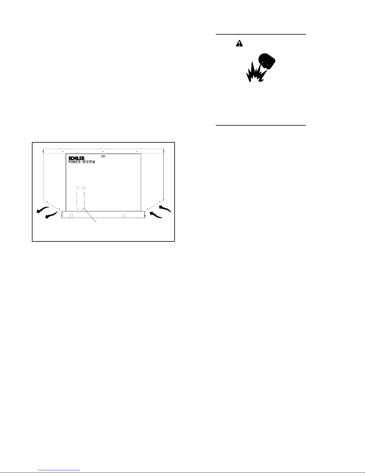
The engine fan draws cooling air through the opening in
the base next to the battery. The generator fan draws
cooling air through an opening on the rear wall of the
enclosure. The cooling air flows to the alternator at the
far end of the unit and over the exhaust system. The air
then mixes with the engine exhaust and is discharged at
the cabinet outlet. To prevent generator set damage
caused by overheating, keep the housing cooling inlets
and outlets clean and unobstructed at all times. See
Figure 3-6.
Note: Do not block the generator set cooling air inlet or
mount other equipment above it. Overheating
and severe generator damage may occur.
WARNING
Sulfuric acid in batteries.
Can cause severe injury or death.
Wear protective goggles and clothing.
Battery acid may cause blindness and
burn skin.
Battery electrolyte is a diluted sulfuric acid. Battery acid
can cause severe injury or death. Battery acid can cause
blindness and burn skin. Always wear splashproof safety
goggles, rubber gloves, and boots when servicing the battery.
Do not open a sealed battery or mutilate the battery case. If
battery acid splashes in the eyes or on the skin, immediately
flush the affected area for 15 minutes with large quantities of
clean water. Seek immediate medical aid in the case of eye
contact. Neveradd acid to a battery after placing the battery in
service, as this may result in hazardous spattering of battery
acid.
Outlet
1. Air intake (on back; specs GM24829 and later)
1
Inlet
GM24829
Figure 3-6 Cooling Air Intake and Exhaust
3.7 Exhaust System
Remove all combustible materials from the exhaust
location. Combustible materials include building
materials as well as natural surroundings. Keep dry field
grass, foliage, and combustible landscaping material a
minimum of 0.3 m (1 ft.) from the exhaust outlet.
Periodically inspect the exhaust system components
(exhaust manifold, exhaust line, flexible exhaust,
clamps, silencer, and outlet pipe) for cracks and
corrosion.
D Check for corroded or broken metal parts and replace
them as needed.
D Check for loose, corroded, or missing clamps and
hangers. Tighten or replace clamps and/or hangers
as needed.
Battery acid cleanup. Battery acid can cause severe
injury or death. Battery acid is electrically conductive and
corrosive. Add 500 g (1 lb.) of bicarbonate of soda (baking
soda) to a container with 4 L (1 gal.) of water and mix the
neutralizing solution. Pour the neutralizing solution on the
spilled battery acid and continue to add the neutralizing
solution to the spilled battery acid until all evidence of a
chemical reaction (foaming) has ceased. Flush the resulting
liquid with water and dry the area.
Battery gases. Explosion can cause severe injury or
death. Battery gases can cause an explosion. Do not smoke
or permit flames or sparks to occur near a battery at any time,
particularly when it is charging. Do not dispose of a battery in a
fire. To prevent burns and sparks that could cause an
explosion, avoid touching the battery terminals with tools or
other metal objects. Remove all jewelry before servicing the
equipment. Discharge static electricity from your body before
touching batteries by first touching a grounded metal surface
away from the battery. To avoid sparks, do not disturb the
battery charger connections while the battery is charging.
Always turn the battery charger off before disconnecting the
battery connections. Ventilate the compartments containing
batteries to prevent accumulation of explosive gases.
D Check for and remove loose insulation in the exhaust
duct.
D Check that the exhaust outlet is clear.
TP-6049 9/0214 Section 3 Scheduled Maintenance
Page 25
Battery short circuits. Explosion can cause severe injury
or death. Short circuits can cause bodily injury and/or
equipment damage. Disconnect the battery before generator
set installation or maintenance. Remove all jewelry before
servicing the equipment. Use tools with insulated handles.
Remove the negative (--) lead first when disconnecting the
battery. Reconnect the negative (--) lead last when
reconnecting the battery. Never connect the negative (--)
battery cable to the positive (+) connection terminal of the
starter solenoid. Do not test the battery condition by shorting
the terminals together.
Refer to this section for general battery information and
maintenance. All generator set models use a negative
ground with a12-volt engine electrical system. Consult
the generator set nameplate for the engine electrical
system voltage. Consult the generator spec sheet for
battery capacity recommendations for replacement
purposes. Wiring diagrams provide battery connection
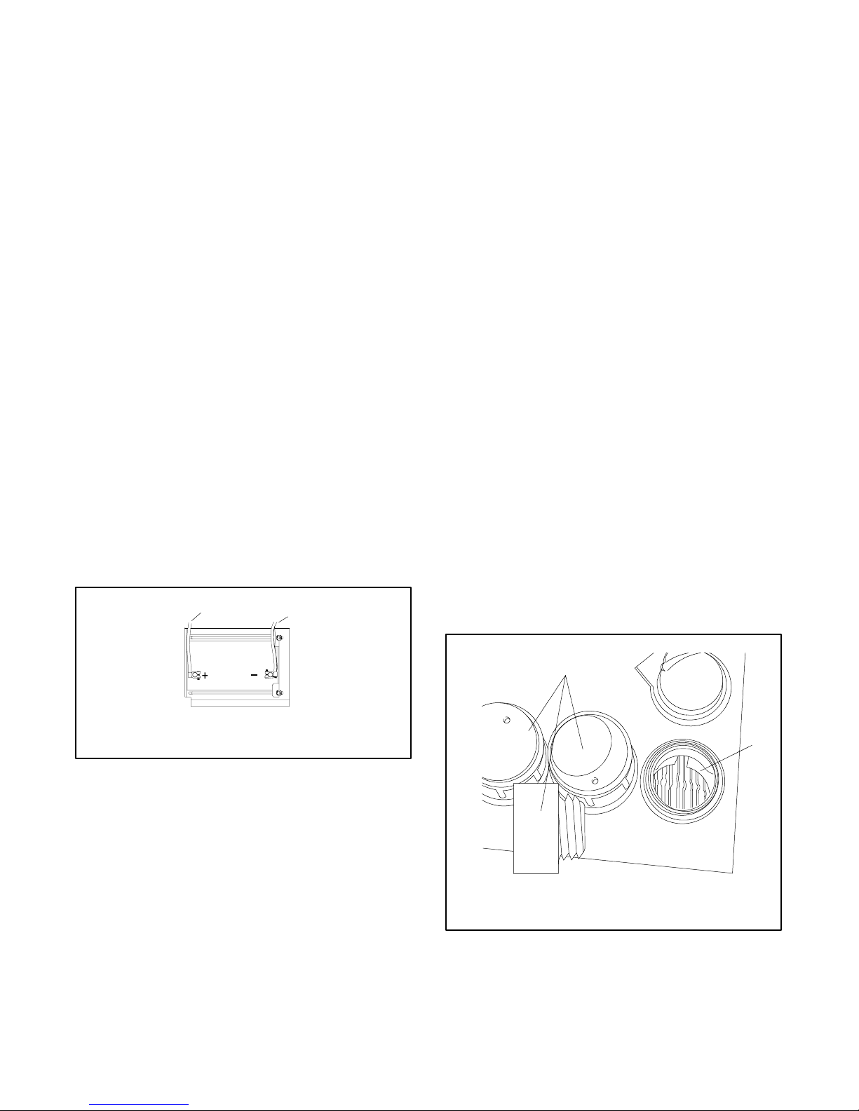
information. See Figure 3-7 for typical battery
connections, including multiple battery configurations.
3.8.1 Cleaning the Battery
To prevent dirt and grime buildup, occasionally wipe the
battery with a damp cloth.
To prevent corrosion, maintain tight, dry electrical
connections at the battery terminals. To remove
corrosion from battery terminals, disconnect the cables
from the battery and scrub the terminals with a wire
brush. Clean the battery and cables with a solution of
baking soda and water. Do not allow the cleaning
solution to enter the battery’s cells. After cleaning, flush
the battery and cables with clean water and wipe them
with a dry, lint-free cloth.
After reconnecting the battery cables, coat the battery
terminals with petroleum jelly, silicone grease, or other
nonconductive grease.
3.8.2 Checking Battery Electrolyte
Level
Check the electrolyte level and specific gravity of
batteries with filler caps. Maintenance-free batteries do
not require electrolyte level checking or specific gravity
testing.
Clean the battery and cables and tighten battery
terminals using the service schedule recommendations.
Clean the battery by wiping it with a damp cloth. Keep
the electrical connections dry and tight.
1
1. To positive (+) terminal on starter solenoid.
2. To ground (--) terminal on or near starter motor.
2
EZ-273000-J
Figure 3-7 12-Volt Engine Electrical System Single
Starter Motor, Typical Battery Connection
Check the battery electrolyte level before each startup.
Remove the filler caps and verify that the electrolyte
level reaches the bottoms of the filler holes; see
Figure 3-8. Refill as necessary with distilled water or
clean tap water. Do not add electrolyte. Install and
tighten filler caps. After adding water to the battery in
freezing temperatures, run the generator set
20--30 minutes to mix the added water and the battery
electrolyte. Mixing the water and the electrolyte
prevents the added water from freezing and damaging
the battery.
1
2
TP-6049 9/02 15Section 3 Scheduled Maintenance
5810321
1. Filler caps
2. Electrolyte level
Figure 3-8 Checking Electrolyte Level
Page 26
3.8.3 Checking Electrolyte Specific
Gravity
Use a battery hydrometer to check the specific gravity of
the electrolyte in each battery cell. Use the
hydrometer’s test instructions, if available, or Figure 3-9
for bead-type testers.
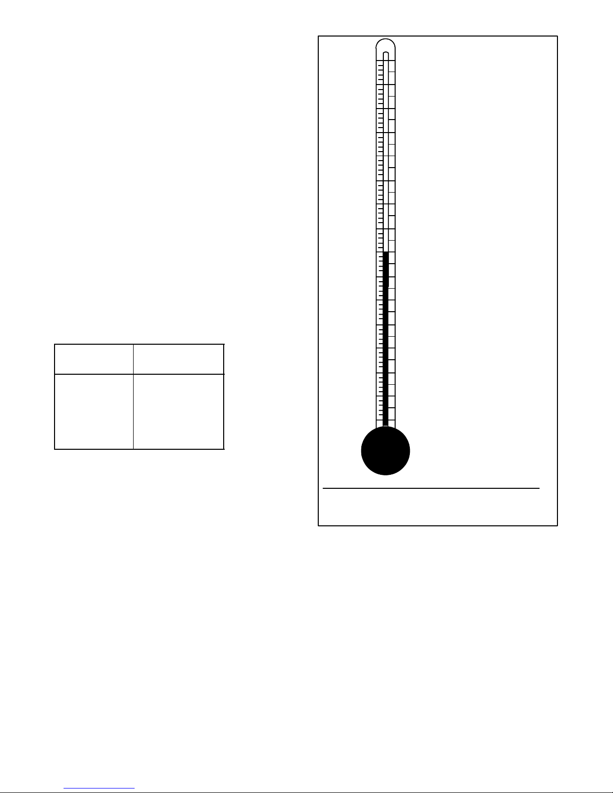
Temperature affects specific gravity; correct the
indicated hydrometer readings for temperature. If the
hydrometer does not have a correction table, use
Figure 3-10. A fully charged battery should have a
specific gravity of 1.260 with the electrolyte at 26.7 _C
(80_F). Charge the battery if the specific gravity from
cell to cell varies by more than 0.01. Charge the battery
if the specific gravity is less than 1.215 with the
electrolyte at 26.7_C(80_F).
3.8.4 Charging
Use a battery charger to maintain a fully charged battery
when the generator set is used in a standby application.
The engine battery-charging system charges the
battery while the generator set is running.
Number of
Beads Floating
5 Overcharged
4 Full Charge
3 Adequate Charge
1, 2 Low Charge
0 Battery Dead
Battery
Condition
°C °F
71.1
65.6
60.0
54.4
48.9
43.3
37.8
32.2
26.7
21.1
15.6
10
4.4
-- 1 . 1
-- 6 . 7
-- 12.2
160
150
140
130
120
110
100
Correction
+ .032
+ .030
+ .028
Example 1:
+ .026
Temperature below 26.7
+ .024
+ .022
Hydrometer Reading 1.250
+ .020
Electrolyte Temperature
+ .018
+ .016
+ .014
+ .012
+ .010
+ .008
+ .006
90
80
70
60
50
40
30
20
10
+ .004
+ .002
0
-- .002
-- .004
--. 006
-- .008
-- .010
-- .012
-- .014
-- .016
-- .018
-- .020
-- .022
-- .024
-- .026
-- .028
°C(20°F)
--6.7
Subtract .024 Specific Gravity
Corrected Specific Gravity is 1.226
Example 2:
Temperature above 26.7
Hydrometer Reading 1.235
Electrolyte Temperature
°C (100°F)
37.8
Add .008 Specific Gravity
Corrected Specific Gravity is
1.243
°C(80°F)
°C(80°F)
Figure 3-9 Electrolyte Testing Chart
The temperature correction amounts to about .004 (4 points) of
specific gravity for each 5.5°C(10°F) change in electrolyte
temperature.
5810322
Figure 3-10 Specific Gravity Temperature Correction
TP-6049 9/0216 Section 3 Scheduled Maintenance
Page 27

3.9 Storage Procedure
3.9.3 Cylinder Lubrication
Perform the following storage procedure before
removing the generator set from service for three
months or longer. Follow the engine manufacturer’s
recommendations for storage, if available.
Note: Run the generator set monthly whenever
possible.
3.9.1 Lubricating System
1. Operate the generator set until it reaches operating
temperature, or about 15 minutes.
2. Stop the generator set.
3. While the engine is still warm, drain the engine
lubrication oil from the engine crankcase.
4. Refill the engine crankcase with oil. See Section
3.3.3 for oil recommendations.
5. Run the generator set for a few minutes to
distribute the clean oil.
6. Stop the generator set.
3.9.2 Fuel System
1. Start the generator set.
1. Remove the spark plugs.
2. Pour one tablespoon of engine oil into each spark
plug hole. Install the spark plugs and ground the
spark plug leads. Do not connect the leads to the
plugs.
3. Toggle the generator set master switch to crank the
engine two or three revolutions to lubricate the
cylinders.
3.9.4 Exterior Preparation
1. Clean the exterior surface of the generator set.
2. Seal all openings in the engine with nonabsorbent
adhesive tape.
3. Mask all areas to be used for electrical contact.
4. Spread a light film of oil over unpainted metallic
surfaces to prevent rust and corrosion.
3.9.5 Battery
Perform battery storage last.
1. Place the generator set master switch in the
OFF/RESET position.
2. With the generator set running, shut off the gas
supply.
3. Run the generator set until the engine stops.
4. Place the generator set master switch in the
OFF/RESET position.
2. Disconnect the battery, negative (--) lead first.
3. Clean the battery. Refer to Section 3.8.1 for the
cleaning procedure.
4. Place the battery in a warm, dry location.
5. Connect the battery to a float/equalize battery
charger, or charge the battery monthly using a
trickle charger. Follow the battery charger
manufacturer’s recommendations.
TP-6049 9/02 17Section 3 Scheduled Maintenance
Page 28

Notes
TP-6049 9/0218 Section 3 Scheduled Maintenance
Page 29

Section 4 Troubleshooting
g
start,startshar
d,lacks
p,p
p
p
This section contains generator set troubleshooting,
diagnostic, and repair information.
If the procedures in this manual do not explain how to
correct the problem, contact an authorized distributor/
dealer. Maintain a record of repairs and adjustments
Use the following chart to diagnose and correct common
problems. First check for simple causes such as a dead
engine starting battery or an open circuit breaker. The
performed on the equipment. Use the record to help
describe the problem and repairs or adjustments made
to the equipment.
chart includes a list of common problems, possible
causes of the problem, and recommended corrective
actions.
Note: Contact an authorized distributor/dealer if the
corrective actions described in the following chart
do not solve the problem.
Problem Possible Cause Corrective Action
The generator set
does not crank.
The generator set
cranks but does not
power, or operates
erratically.
No AC output. AC circuit breaker in the OFF position Place the circuit breaker in the ON position.
Low output or
excessive drop in
voltage.
Generator set stops
suddenly.
Battery weak or dead Recharge or replace; check battery charger operation.
Battery connections reversed or poor Check the connections.
Controller fuse blown Replace the fuse.
Generator master switch in the OFF position Move the master switch to the RUN position.
Air cleaner clogged Clean and/or replace the air cleaner.
Battery weak or dead Recharge or replace the battery.
Battery connection poor Clean and tighten the battery connections.
Spark plug wire connection loose Check the spark plug wires.
Low oil pressure shutdown Check the oil level.
Fuel pressure insufficient Check the fuel supply and valves.
Engine malfunction Contact the distributor/dealer.
AC circuit breaker tripping because of overload Reduce the load on the generator set.
AC circuit breaker tripping because of short circuit Correct the cause of the short circuit. Contact the
Voltage regulator fuse blown Replace the fuse.
Generator set overloaded Reduce the load.
Low oil pressure shutdown Check the oil level.
Outoffuel Check fuel supply.
Overcrank shutdown Reset the controller. If the overcrank fault occurs again,
Controller fuse blown Replace the fuse. If the fuse blows again, contact the
Overspeed shutdown Reset the controller. If the overspeed fault occurs again,
Generator set master switch in the OFF/RESET
position
Engine malfunction Contact the distributor/dealer.
Check battery charging circuit (circuit breaker, module, and
wiring), if equipped.
distributor/dealer.
contact the distributor/dealer.
distributor/dealer.
contact the distributor/dealer.
Move the switch to the correct position (RUN or AUTO).
Figure 4-1 General Troubleshooting Chart
TP-6049 9/02 19Section 4 Troubleshooting
Page 30

Notes
TP-6049 9/0220 Section 4 Troubleshooting
Page 31
5.1 Specification Numbers
At the time of print, this manual applied to the model
numbers and specification (spec) numbers in
Figure 5-1. On occasion the manufacturer may provide
this manual with units that are not listed below, such as
when similar new specs are created prior to the updated
reprint or in other cases when the manual is a suitable
substitute for a manual under development.
Controller
Model No.
8.5RMY PA-195021 No
8.5RMY PA-195025 Yes
8.5RMY GM16902-GA1 Ye s
8.5RMY GM24829-GA1 Ye s
11RMY PA-195022 No
11RMY PA-195026 Yes
11RMY GM16902-GA2 Ye s
11RMY GM24829-GA2 Ye s
Figure 5-1 Generator Set Specification Numbers
Spec. No.
Fault Lamp
Section 5 Wiring Diagrams
R
ON
50
RESET/
RUN
F1 10 AMP
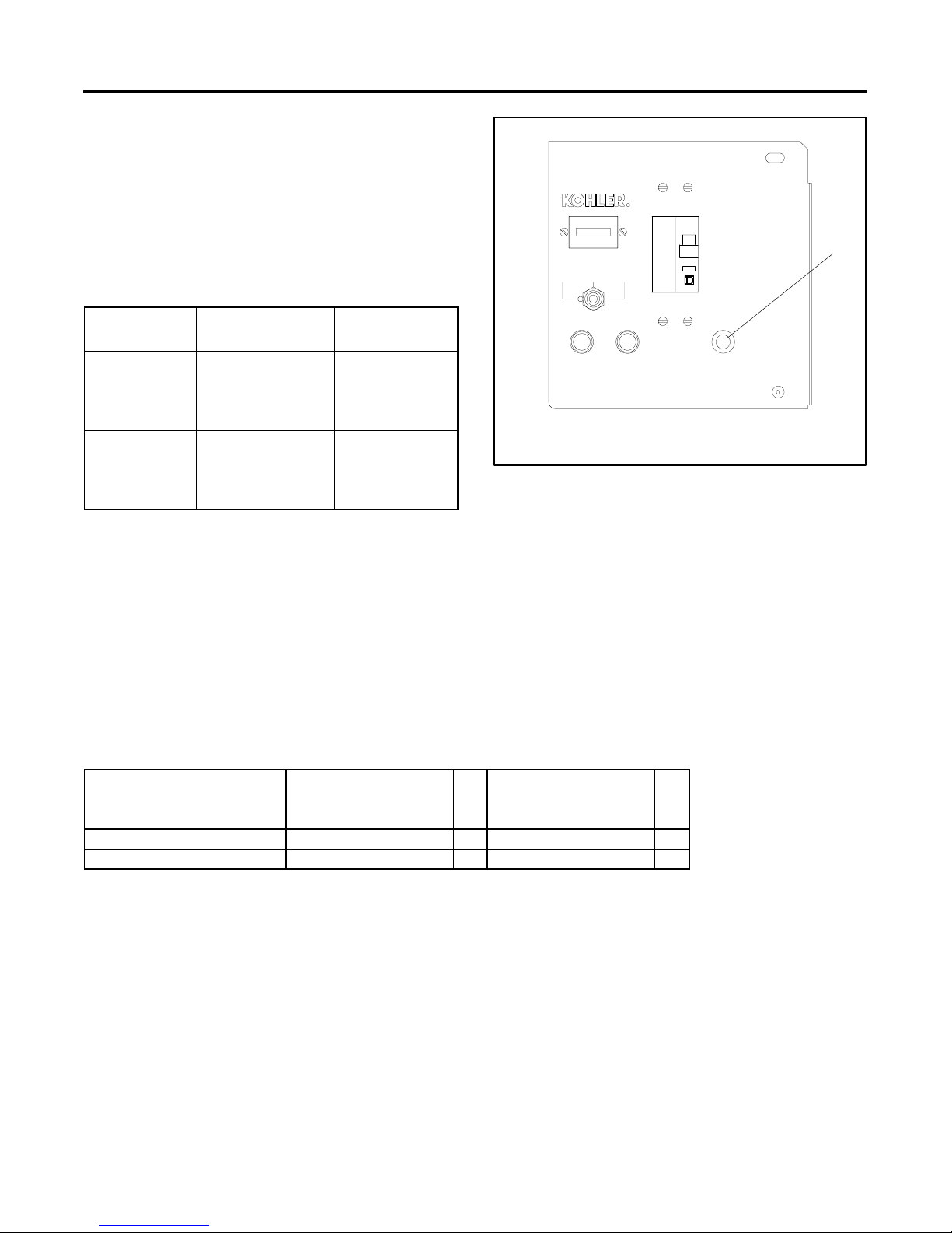
1. Fault lamp (not included on early models)
AUTOOFF
F2 10 AMP
TYPE ABCTYPE ABC
Figure 5-2 Controller
OFF
1
FAULT
GM10615
5.2 Controller Wiring Diagram
Reference
Compare the front of the generator set controller with
Figure 5-2. Use the version 1 diagrams for units that do
not have a fault lamp on the front of the controller. Use
the version 2 diagrams for units that have a fault lamp.
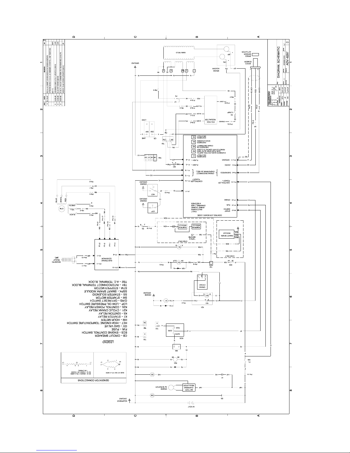
Figure 5-3 lists the wiring diagram numbers and
locations.
Controllers
Without Fault Lamps
Wiring Diagram Description
Schematic Diagram ADV-6297-D 23 ADV-6524- 25
Point-to-Point Wiring Diagram GM10164-A 24 GM10619- 26
(Version 1)
Pg
Figure 5-3 Controller Wiring Diagrams
Controllers
With Fault Lamps
(Version 2)
Pg
TP-6049 9/02 21Section 5 Wiring Diagrams
Page 32

Notes
TP-6049 9/0222 Section 5 Wiring Diagrams
Page 33
TP-6049 9/02 23Section 5 Diagrams and Drawings
Relay Controller, Schematic Diagram, 1 Phase, ADV-6297-D
Page 34
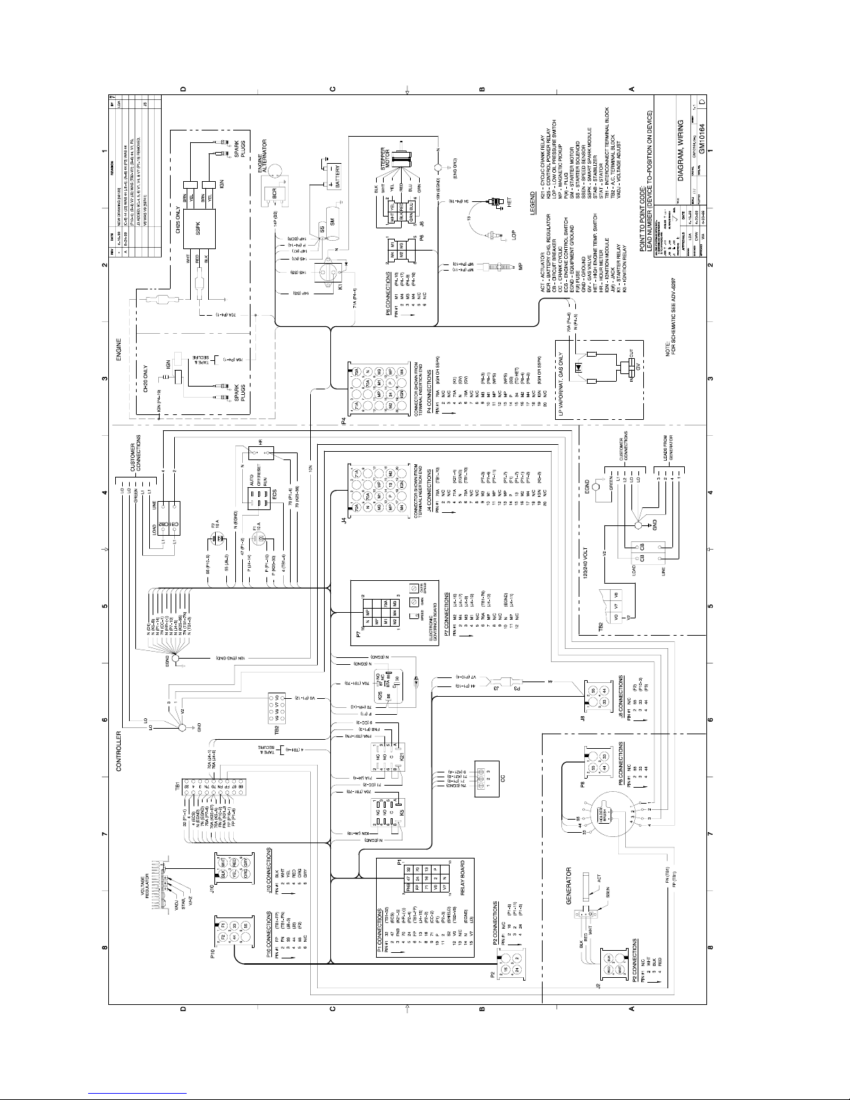
TP-6049 9/0224 Section 5 Diagrams and Drawings
Relay Controller, Point-to-Point Wiring Diagram, 1 Phase, GM10164-A
Page 35
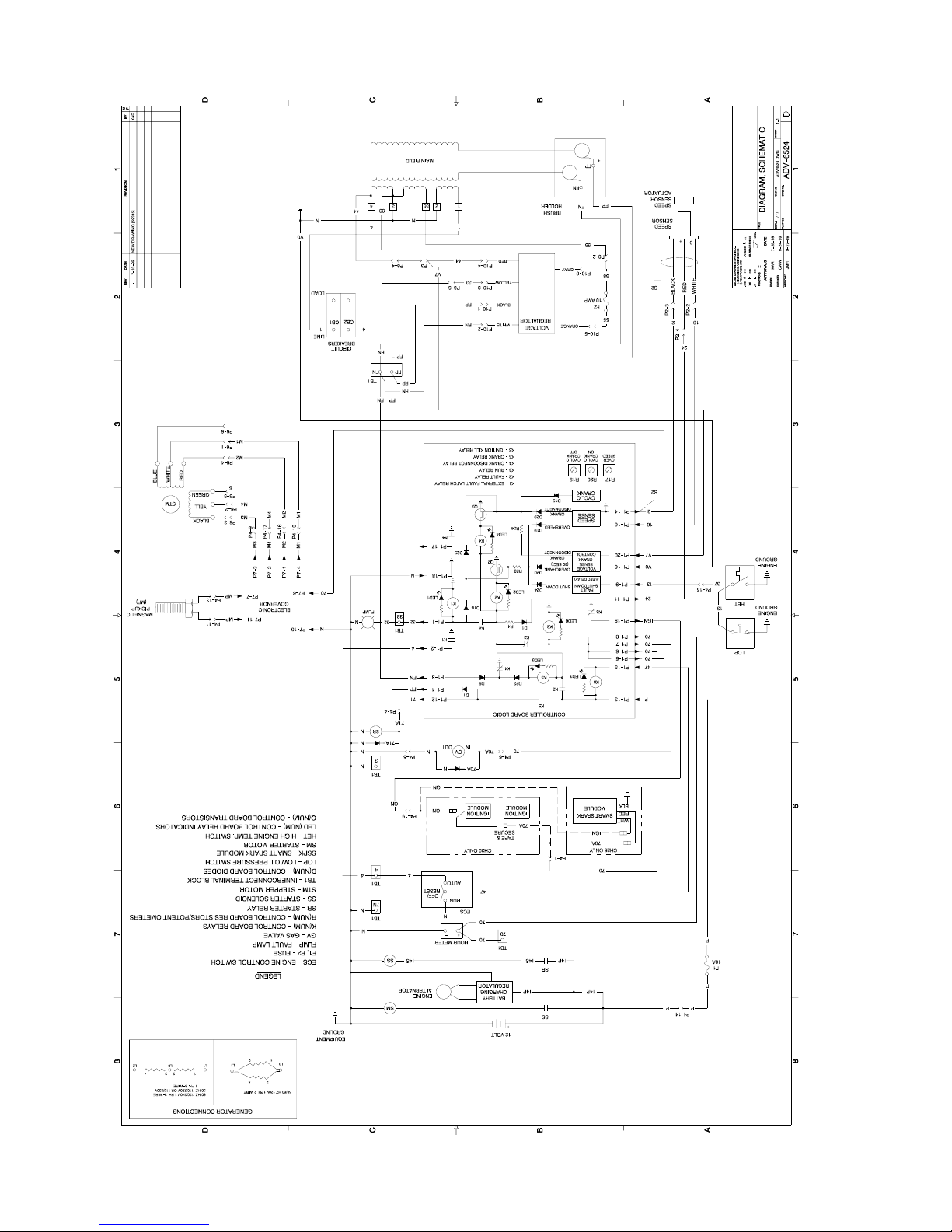
TP-6049 9/02 25Section 5 Diagrams and Drawings
Relay Controller, Schematic Diagram, ADV-6524-
Page 36
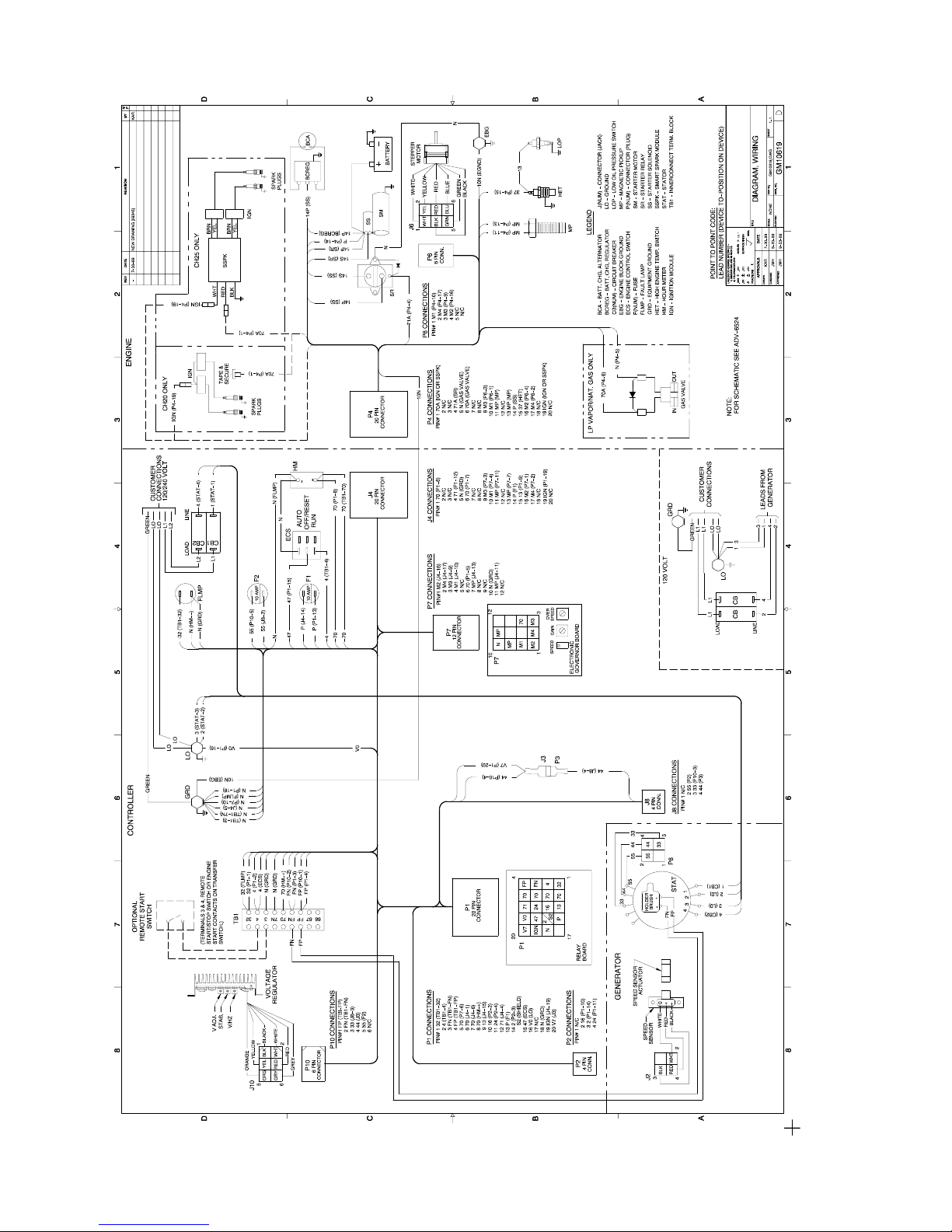
TP-6049 9/0226 Section 5 Diagrams and Drawings
6
Relay Controller, Point-to-Point Wiring Diagram, GM10619-
Page 37
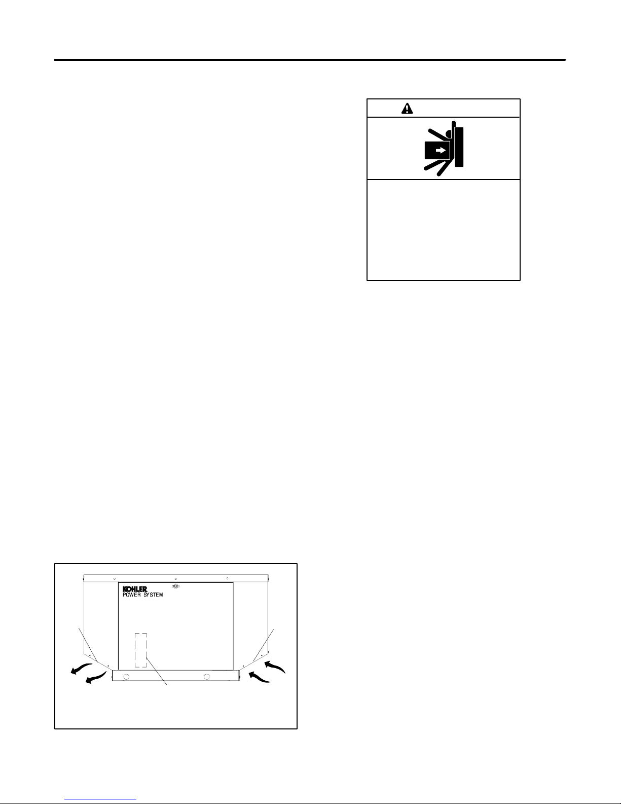
Section 6 Installation
6.1 General
Installation must comply with these installation
instructions. Install the generator set to comply with
state and local code requirements.
Use the specifications provided here only in the initial
planning. Use the respective spec sheets, dimension
drawings, and wiring diagrams for installation. Contact
an authorized service distributor/dealer for the most
current information.
Provide a 110- or 120-volt outlet connected to the utility
power supply for the carburetor heater and battery
charger, if used.
6.2 Air Requirements
The generator set requires correct air flow for cooling
and combustion. The inlet and outlet openings in the
sound enclosure housing provide the cooling and
combustion air. Figure 6-1 shows the locations of the
cooling air intake and exhaust vents. Do not block or
otherwise interfere with the airflow through these
openings.
Inspect the air inlet and outlet openings inside and
outside the housing to ensure that debris does not block
the air flow. Mount the generator so that the hot exhaust
does not blow on plants or shrubs. Maintain a minimum
of 0.3 m (1 ft.) between the exhaust outlet and
combustible materials.
6.3 Exhaust Requirements
6.4 Weight
WARNING
Unbalanced weight.
Improper lifting can cause severe
injury or death and equipment
damage.
Do not use lifting eyes.
Lift the generator set using lifting bars
inserted through the lifting holes on
the skid.
The genertor set weighs approximately 182 kg
(400 lbs.). Use lifting bars inserted through the holes in
the skid to lift the unit. See Figure 6-2 for lifting hole
locations.
6.5 Generator Set Inspection
Complete a thorough inspection of the generator set.
Check for the following:
1. Inspect the generator set for loose or damaged
parts or wires. Repair or tighten any loose parts
before installation.
2. Check the engine oil. Fill, if necessary, with the
recommended make and grade of oil. See
Section 3.3.3 for engine oil recommendations.
The exhaust system is complete for generator sets
installed outdoors. Do not install this generator set
indoors.
1
2
1. Exhaust outlet
2. Alternator air intake (on back)
3. Engine air intake
Figure 6-1 Cooling Air Intake and Exhaust
TP-6049 9/02 27Section 6 Installation
3
GM24829
6.6 Mounting
Do not install the generator set directly on the ground.
Mount the generator set on a level pad. Use a simple
concrete slab, precast base, or other non-combustible,
stable material. The mounting pad should be at least
1320 mm (52 in.) long and 800 mm (31.6 in.) wide.
Center the unit on the mounting pad.
Figure 6-2 shows the generator set dimensions,
mounting hole locations, and fuel and electric stub-up
locations. The drawing dimensions are shown in mm
with inches in parentheses.
Secure the generator set and ensure that it does not
move while operating.
Page 38
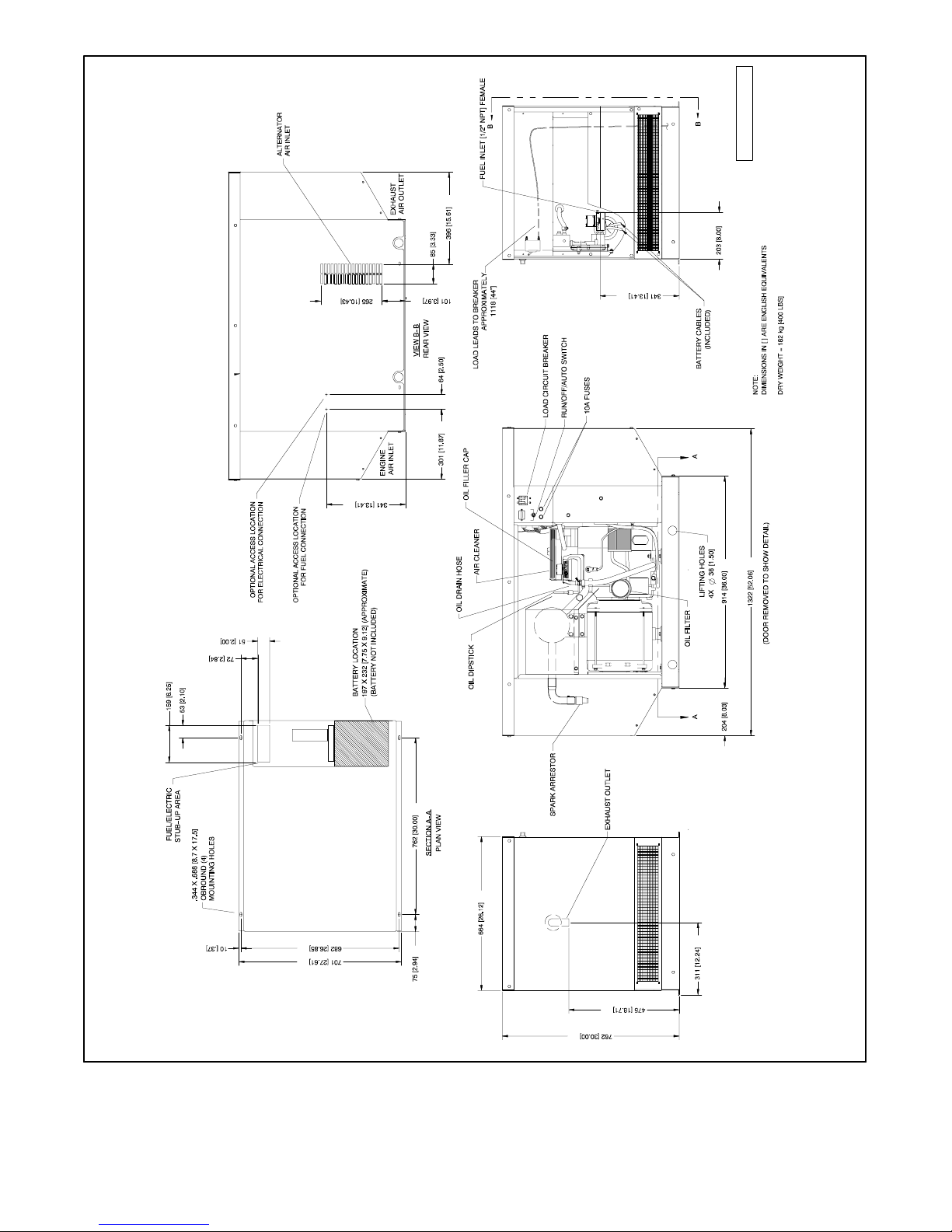
METRIC CAD FILE
ADV-6788
Figure 6-2 Generator Set Mounting Details and Dimensions
TP-6049 9/0228 Section 6 Installation
Page 39
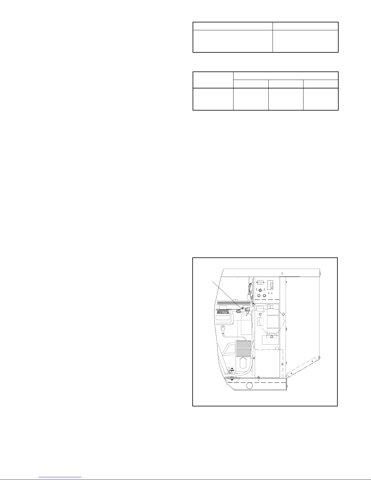
6.7 Fuel System
The generator set operates using natural gas or LP
vapor fuel. The multi-fuel system allows conversion
from natural gas to LP vapor (or vice-versa) in the field
while maintaining emissions-standard compliance. A
trained technician or authorized distributor/dealer can
convert the fuel system. Generator sets with multi-fuel
systems are CARB- and EPA-certified for both natural
gas and LP vapor fuels.
6.7.1 Fuel Supply
Comply with local, state, and federal codes regarding
the correct storage of fuel. Because of variable climates
and geographical considerations, contact an authorized
service distributor/dealer for fuel system planning and
installation. Figure 6-2 shows the location of the fuel
inlet connection, the fuel and electric stub-up area, and
the rear panel access holes. Bring the fuel supply lines
through either the bottom or the rear access openings.
Protect all fuel lines from machinery or equipment
contact, adverse weather conditions, and environmental
damage.
Verify that the output pressure from the primary gas
utility (or LP tank) pressure regulator is 1.7--2.7 kPa
(7--11 in. water column) and that the utility gas meter
flow rate is sufficient to supply the generator set plus all
other gas-consuming appliances. Figure 6-3 shows the
flow rate required for the generator set. Contact the
natural gas utility for flow rate information or a gas meter
upgrade.
Generator Set Model Gas Flow Rate, Btu/hr.
8.5RMY 132,000
11R MY 192,000
12RMY 202,000
Figure 6-3 Natural Gas Flow Rate
Maximum Pipe Length m (ft.)
Pipe Size
3/4 in. NPT 18.3 (60) 9.2 (30) 9.2 (30)
1 in. NPT 61 (200) 30 (100) 30 (100)
1 1/4 in. NPT 91.5 (300) 68.6 (225) 68.6 (225)
8.5RMY 11RMY 12RMY
Figure 6-4 Maximum Natural Gas Pipe Length
6.7.3 Single-Fuel Systems
Generator sets with single-fuel systems are equipped
with the fuel valve shown in Figure 6-5 and have
specification numbers starting with PA-.
Single-fuel generator sets that have the decal shown in
the Introduction section are emission-certified. The fuel
systems on emission-certified single-fuel generator sets
are not field-convertible or adjustable. The factory sets
the fuel system for the specified fuel and seals it to
prevent adjustments.
Note: Do not adjust or convert the fuel system on an
emission-certified single-fuel generator set.
Changing the fuel or adjusting the fuel systems
on these units may violate federal or state laws.
1
6.7.2 Fuel Pipe Size
Ensure that the natural gas pipe size and length meet
RUN
TYPEABC
F110 AMP
ON
OFF
RESET/
AUTOOFF
F210 AMP
TYPEABC
the specifications in Figure 6-4. Measure the pipe
length from the primary gas pressure regulator to the
pipe connection on the generator set fuel inlet. Add
2.4 m (8 ft. ) to the measured length for each 90 degree
elbow. Compare the pipe size and length with the chart
in Figure 6-4. If the piping is longer than the maximum
length shown for that size, replace it with the specified
size before proceeding.
Contact the local LP provider for LP installation
information.
P-358000-C
1. Fuel valve
Figure 6-5 Single-Fuel Generator Set Fuel Valve
Location
TP-6049 9/02 29Section 6 Installation
Page 40
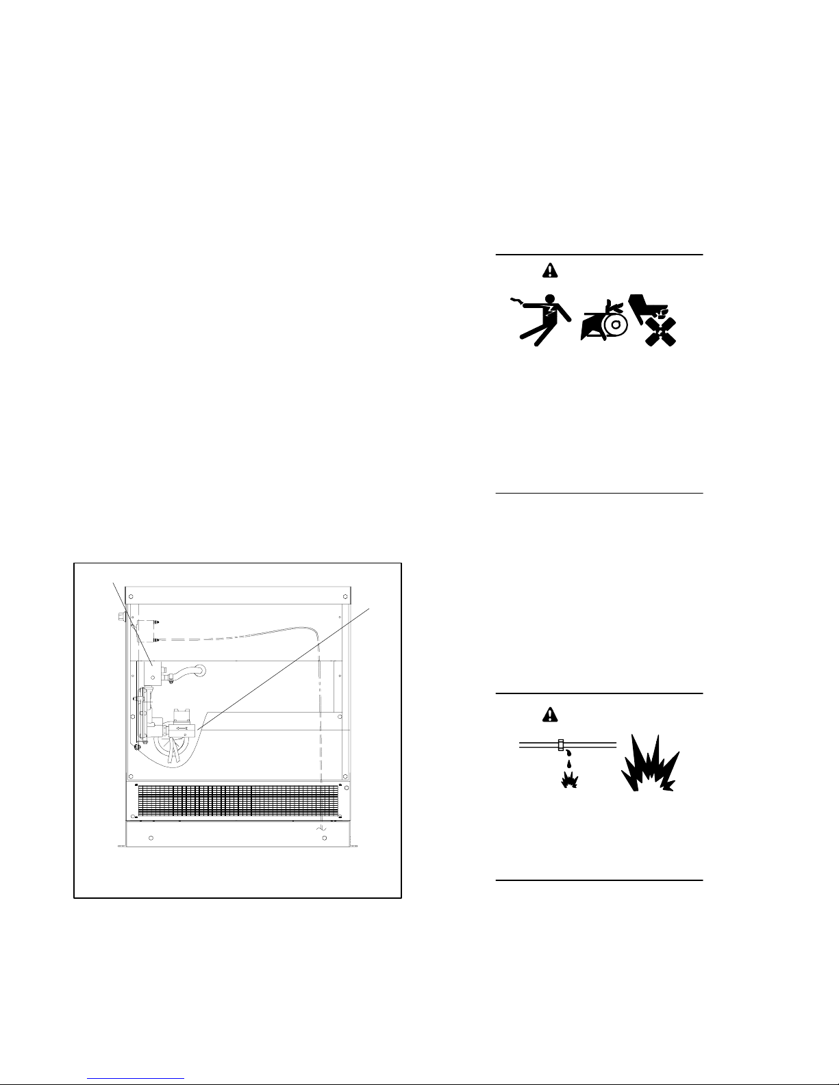
Single-fuel generator sets that are not
emission-certified do not have the emission decal. An
authorized distributor/dealer can convert the fuel
system from natural gas to LP vapor (or vice-versa) on a
non-certified unit. Converting the fuel system includes
adjusting the fuel metering valve and checking the
exhaust emissions. The generator set service manual
explains the adjustment procedures.
6.7.4 Multi-Fuel Systems
Generator sets with multi-fuel systems are CARB- and
EPA-certified for both natural gas and LP vapor fuels.
Multi-fuel units are equipped with the fuel block shown in
Figure 6-6 and have specification numbers beginning
with GM. The multi-fuel system allows conversion from
natural gas to LP vapor (or vice-versa) in the field while
maintaining emissions-standard compliance. A trained
technician or authorized distributor/dealer can convert
the fuel system.
6.7.5 Fuel Conversion (multi-fuel
models only)
Two fuel connections on the fuel block allow fieldconversion between natural gas and LP vapor. The fuel
metering valves are factory-set and sealed to comply
with applicable emission standards and to provide the
best possible hot and cold starting.
1
2
Note: Do not adjust the factory-sealed fuel-metering
adjustments on the fuel block. Changing the
fuel-metering adjustments on multi-fuel units
may violate federal or state laws.
The manufacturer ships the generator set with the fuel
system connected for natural gas. To convert to LP gas,
use the following procedure to move the fuel line from
the natural gas outlet port to the LP outlet port in the fuel
block (or from the LP outlet to the natural gas outlet to
convert from LP to natural gas). See Figure 6-6 for the
fuel block and fuel inlet locations.
WARNING
Accidental starting.
Can cause severe injury or death.
Disconnect the battery cables before
working on the generator set.
Remove the negative (--) lead first
when disconnecting the battery.
Reconnect the negative (--) lead last
when reconnecting the battery.
Disabling the generator set. Accidental starting can
cause severe injury or death. Before working on the
generator set or connected equipment, disable the generator
set as follows: (1) Move the generator set master switch to the
OFF position. (2) Disconnect the power to the battery charger.
(3) Remove the battery cables, negative (--) lead first.
Reconnect the negative (--) lead last when reconnecting the
battery. Follow these precautions to prevent starting of the
generator set by an automatic transfer switch, remote
start/stop switch, or engine start command from a remote
computer.
OUT IN
1. Fuel block
2. Fuel inlet, 1/2 in. NPT female
Figure 6-6 Multi-Fuel Generator Set Fuel Block
Location, Air Inlet Side
ADV-6600
WARNING
Explosive fuel vapors.
Can cause severe injury or death.
Use extreme care when handling,
storing, and using fuels.
TP-6049 9/0230 Section 6 Installation
Page 41

Fuel Conversion Procedure for Multi-Fuel
Systems
1. Place the generator set master switch in the OFF
position.
2. Disconnect the power to the battery charger, if
equipped.
3. Disconnect the generator set engine starting
battery, negative (--) lead first.
4. Turn off the fuel supply.
10. Connect the new fuel supply.
11. Turn on the fuel supply and check for leaks using a
gas leak detector.
12. Check that the generator set master switch is in the
OFF position.
13. Reconnect the generator set engine starting
battery leads, negative (--) lead last.
14. Reconnect power to the battery charger, if
equipped.
5. Remove the hose clamp and fuel hose from the
hose fitting in the fuel block. See Figure 6-7.
6. Remove the hose fitting from the natural gas (or
LP) outlet port in the fuel block.
7. Remove the plug from the LP (or natural gas) port
in the fuel block. Clean the plug with a dry cloth or
brush, apply fresh pipe sealant, and install the plug
into the natural gas (or LP) outlet port.
8. Clean the hose fitting with a dry cloth or brush,
apply fresh pipe sealant to the threads, and install
the fitting into the LP (or natural gas) port.
Note: Do not adjust the fuel metering valves.
9. Slide the hose onto the hose fitting and secure it
with the clamp.
1
NG
LP
3
42
6.8 Electrical Connections
6.8.1 Accessory Electrical Connections
Some accessories, including a run relay and a common
fault relay, can be connected to the generator set.
Contact an authorized service distributor/dealer for a list
of accessories.
Have the accessories installed by an authorized
distributor/dealer or a licensed electrician. Follow the
installation instructions provided with each kit. Most
accessories operate on 12 volts DC; some may require
AC line voltage. Use separate conduit for AC and DC
leads to reduce the possibility of electrical interference.
Verify that the leads and conduit do not interfere with the
operation of the generator set or obstruct the service
areas. Verify that the electrical installation complies with
the National Electrical Code (NEC) and all applicable
local and state codes. See Section 5, Wiring Diagrams,
for more information regarding generator set electrical
connections.
5
OUT IN
1. Fuel block
2. Fuel metering valves—factory-sealed, do not adjust
3. Clamp
4. Fuel line hose
5. Plug
6. Fuel inlet, 1/2 in. NPT
Figure 6-7 Fuel Block Connections, Natural Gas
System Shown
TP-6049 9/02 31Section 6 Installation
6
ADV-6600
Page 42
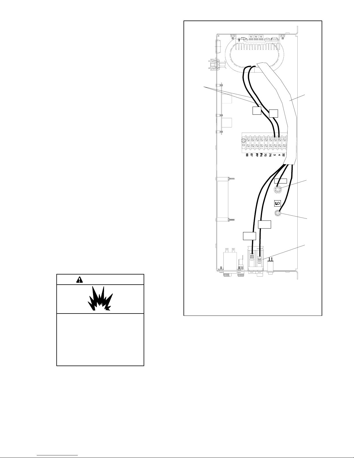
6.8.2 AC Load Lead Connections
Have an authorized distributor/dealer or a licensed
electrician make the following load connections.
Connect the AC output leads in the controller
compartment to the AC circuit breaker. Route AC and
DC leads through the bottom of the generator set or
through flexible conduit directly to the AC circuit breaker
box. See Figure 6-2. Verify that the leads and conduit
do not interfere with the operation of the generator set or
obstruct the service areas.
5
1
See Figure 6-8 and Section 5, Wiring Diagrams, for the
generator set electrical connections. Make the following
AC connections:
1. Connect the output leads going to the transfer
switch (L1/L2 black leads) to the AC circuit breaker
load side (top).
2. Connect the L0 white leads from the ATS and the
main panel to the neutral stud.
3. Connect the green lead to the equipment ground
stud (labeled GRD).
Verify that the electrical installation complies with the
National Electrical Code (NEC) and all applicable local
and state codes.
NOTICE
Canadian installations only. For standby service connect
the output of the generator set to a suitably rated transfer
switch in accordance with Canadian Electrical Code, Part 1.
6.8.3 Battery
6868
L1
3
4
6767
7N7N
7070
FPFP
FNFN
L2
33
44
GRD
3232
2
3
4
WARNING
Explosion.
Can cause severe injury or death.
Relays in the battery charger
cause arcs or sparks.
Locate the battery in a well-ventilated
area. Isolatethe battery charger from
explosive fumes.
GM10615A-A
1. AC load leads
2. Ground terminal (GRD)
3. Neutral terminal (L0)
4. Circuit breaker
5. ATS engine start leads
Figure 6-8 Typical Controller, Top View with
Field-Installed Wiring
TP-6049 9/0232 Section 6 Installation
Page 43
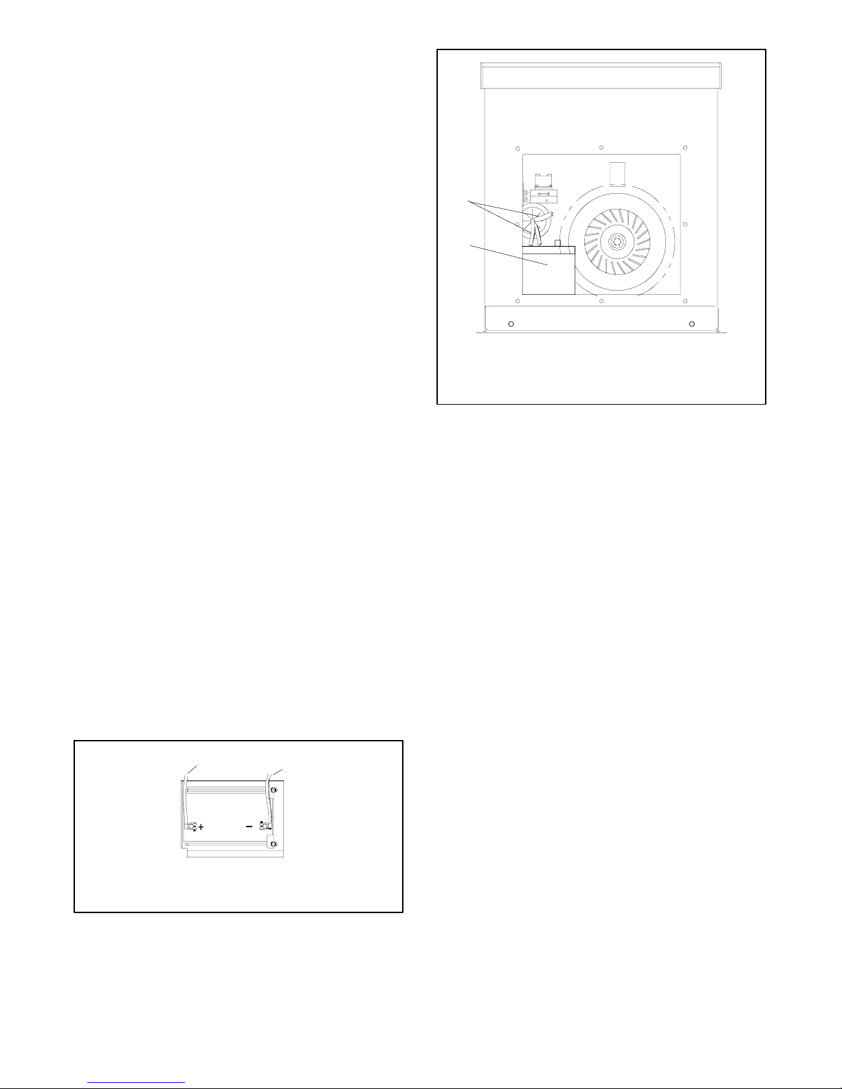
Battery gases. Explosion can cause severe injury or
death. Battery gases can cause an explosion. Do not smoke
or permit flames or sparks to occur near a battery at any time,
particularly when it is charging. Do not dispose of a battery in a
fire. To prevent burns and sparks that could cause an
explosion, avoid touching the battery terminals with tools or
other metal objects. Remove all jewelry before servicing the
equipment. Discharge static electricity from your body before
touching batteries by first touching a grounded metal surface
away from the battery. To avoid sparks, do not disturb the
battery charger connections while the battery is charging.
Always turn the battery charger off before disconnecting the
battery connections. Ventilate the compartments containing
batteries to prevent accumulation of explosive gases.
Battery short circuits. Explosion can cause severe injury
or death. Short circuits can cause bodily injury and/or
equipment damage. Disconnect the battery before generator
set installation or maintenance. Remove all jewelry before
servicing the equipment. Use tools with insulated handles.
Remove the negative (--) lead first when disconnecting the
battery. Reconnect the negative (--) lead last when
reconnecting the battery. Never connect the negative (--)
battery cable to the positive (+) connection terminal of the
starter solenoid. Do not test the battery condition by shorting
the terminals together.
1
2
1. Battery cables and carburetor heater power cord, if
equipped
2. Engine starting battery
OUT IN
Figure 6-10 Battery Location, Engine End
Battery Installation Procedure
A-358000A-C
Use a 12-volt battery with a minimum rating of 675 cold
cranking amps at 0_F. The generator set uses a
negative ground with a 12-volt engine electrical system.
See Figure 6-9 for battery connections. Make sure that
the battery is correctly connected and the terminals are
tight.
Note: The generator set will not start and circuit board
damage may occur if the battery is connected in
reverse.
Figure 6-10 shows the location of the engine starting
battery. Standard battery cables provide easy
connection to the battery. Use the following procedure
to install and connect the battery.
1
1. To positive (+) terminal on starter solenoid.
2. To ground (--) terminal on or near starter motor.
2
EZ-273000-J
Figure 6-9 12-Volt Engine Electrical System Single
Starter Motor Typical Battery Connection
1. Ensure that the starting battery is fully charged
before placing the battery in service.
2. Clean the battery posts and/or adapters if
necessary.
3. Install the battery post adapters, if needed.
4. Place the battery in the housing.
5. Verify that the controller master switch is in the OFF
position.
6. Connect the positive (+) lead to the engine starting
battery.
7. Connect the negative (--) lead to the engine starting
battery.
Refer to Section 3.8 for battery maintenance
instructions.
6.8.4 Battery Charger
Generator sets that are not exercised regularly require
an external battery charger to keep the starting battery
fully charged. Obtain a battery charger from your
generator set supplier. Observe the battery polarity
when connecting the battery charger. Plug the battery
TP-6049 9/02 33Section 6 Installation
Page 44
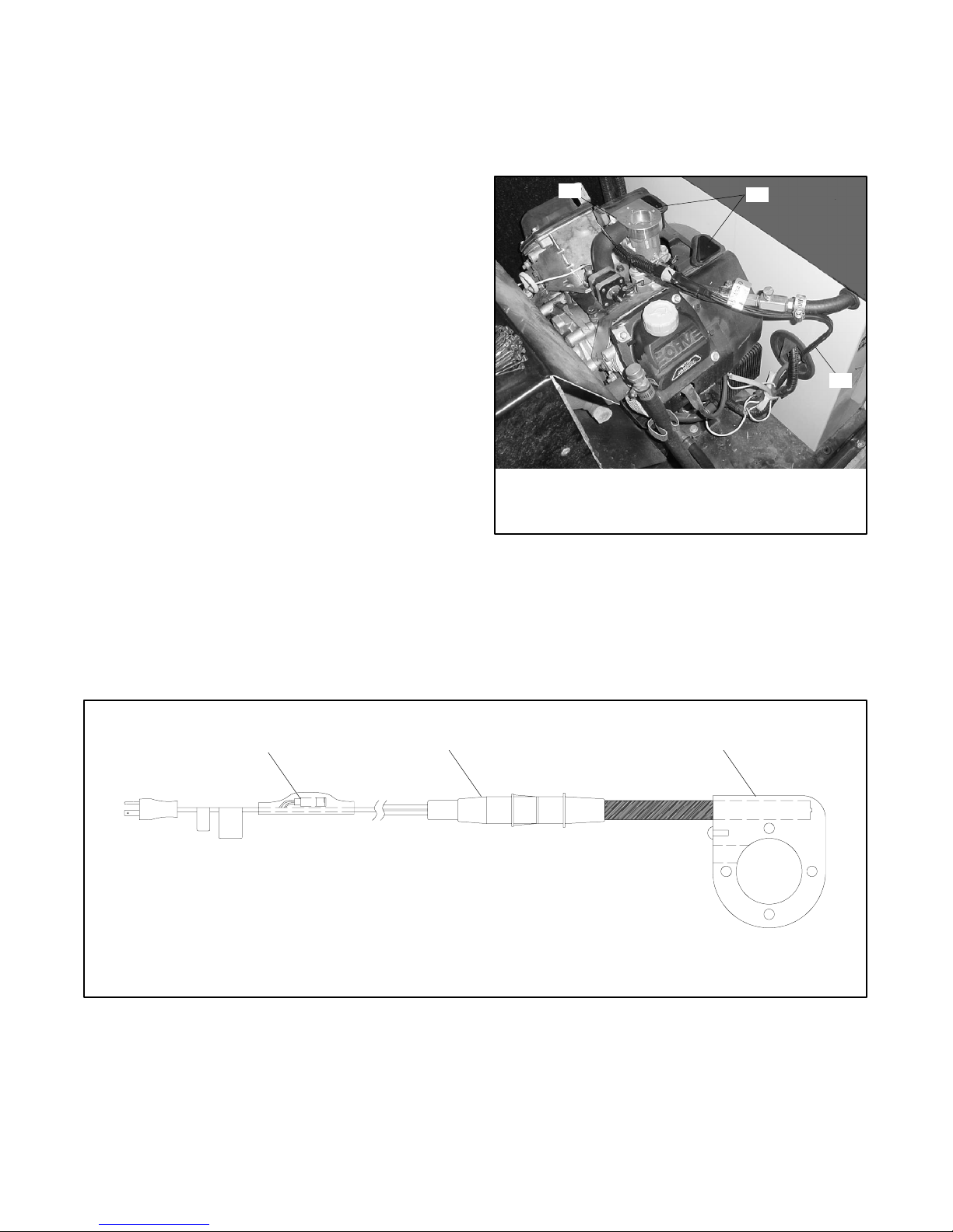
charger into a 110 or 120-volt outlet connected to the
utility power.
Figure 6-11 shows the blower housing covers installed.
The covers are not used on all units.
6.8.5 Carburetor Heater
The generator set may be equipped with a carburetor
heater. The carburetor heater prevents condensation
and carburetor icing. The heater turns on when the
temperature at the thermostat falls below approximately
4_C(40_F) and turns off when the temperature rises
above approximately 16_C(60_F). The thermostat
continously senses temperature and controls the
carburetor heater.
The heater requires a continuous source of 120 V
power. The heater power cord and thermostat are
located in the generator set housing air intake
area/battery compartment. See Figure 6-10. Plug the
carburetor heater into an outlet that has continuous 120
volt power.
Figure 6-11 shows the heater power cord running from
inside the engine compartment to the air intake
area/battery compartment. The heater thermostat is
installed in the cord. Figure 6-12 shows the location of
the thermostat on the power cord.
A DC version of the carburetor heater is available. Refer
to the installation instructions provided with the DC
carburetor heater kit.
1
1. Carburetor heater (air cleaner removed to show heater)
2. Blower housing covers (not used on all units)
3. Carburetor heater power cord
2
3
005tp1
Figure 6-11 Carburetor Heater Power Cord
Note: Do not place the heater thermostat inside the
generator set engine compartment. The
thermostat must be exposed to the ambient air.
The thermostat will shut off power to the heater
when the ambient temperature reaches
approximately 60_F(16_C).
1
1. Thermostat
2. Connector
3. Heater
2 3
Figure 6-12 Carburetor Heater with Thermostat
GM19463
TP-6049 9/0234 Section 6 Installation
Page 45
6.9 Generator Reconnection
The generator set can produce a variety of voltages at
either 50 or 60 Hz. See Figure 6-13. This section gives
voltage reconnection instructions. For frequency
adjustments, refer to the generator set service manual,
TP-5867.
Verify that the installation complies with the National
Electrical Code (NEC) and all applicable local and state
codes.
Wires 60 Hz 50 Hz
3* 120/240 110/220
2[
2[
* Factory connection
[ Field reconnection
Figure 6-13 Generator Connection Options
6.9.1 Voltage Reconnection
240 220
120 110
Disabling the generator set. Accidental starting can
cause severe injury or death. Before working on the
generator set or connected equipment, disable the generator
set as follows: (1) Move the generator set master switch to the
OFF position. (2) Disconnect the power to the battery charger.
(3) Remove the battery cables, negative (--) lead first.
Reconnect the negative (--) lead last when reconnecting the
battery. Follow these precautions to prevent starting of the
generator set by an automatic transfer switch, remote
start/stop switch, or engine start command from a remote
computer.
WARNING
Hazardous voltage.
Can cause severe injury or death.
Operate the generator set only when
all guards and electrical enclosures
areinplace.
Moving rotor.
The following information illustrates the reconnection of
4-lead generator sets. Refer to the following connection
schematics. Follow all the safety precautions and
instructions at the beginning of this manual and in this
section while performing the reconnection procedure.
Note: Order voltage reconnection decal 246242 from
an authorized service distributor/dealer and affix
the decal to the generator set after reconnecting
to a voltage different from the nameplate.
WARNING
Accidental starting.
Can cause severe injury or death.
Disconnect the battery cables before
working on the generator set.
Remove the negative (--) lead first
when disconnecting the battery.
Reconnect the negative (--) lead last
when reconnecting the battery.
Grounding electrical equipment. Hazardous voltage can
cause severe injury or death. Electrocution is possible
whenever electricity is present. Open the main circuit
breakers of all power sources before servicing the equipment.
Configure the installation to electrically ground the generator
set, transfer switch, and related equipment and electrical
circuits to comply with applicable codes and standards. Never
contact electrical leads or appliances when standing in water
or on wet ground because these conditions increase the risk of
electrocution.
Short circuits. Hazardous voltage/current can cause
severe injury or death. Short circuits can cause bodily injury
and/or equipment damage. Do not contact electrical
connections with tools or jewelry while making adjustments or
repairs. Remove all jewelry before servicing the equipment.
TP-6049 9/02 35Section 6 Installation
Page 46
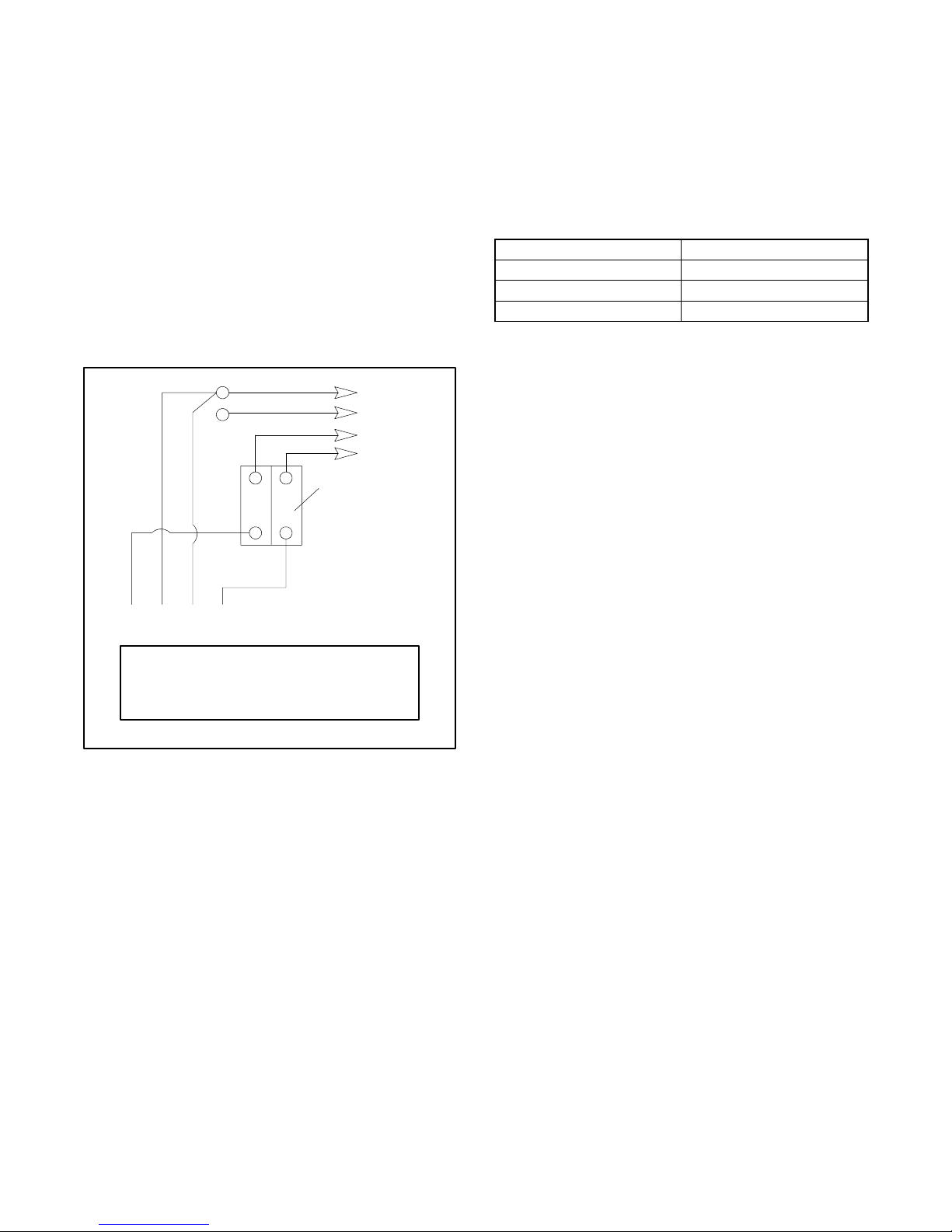
6.9.2 Factory Connections, 110/220 Volt
50 Hz or 120/240 Volt 60 Hz
Generator sets are available from the factory connected
for 110/220 Volt 50 Hz or 120/240 Volt 60 Hz. See
Figure 6-14 for the factory connections.
6.9.3 Reconnection Options
The following reconnections can be made using the
factory two-pole circuit breaker provided. It is the
responsibility of the individual performing the
reconnection to meet all the electrical codes.
Leads L1 and L2 are of different phases. Never connect
leads L1 and L2 together. After connection adjust the
voltage regulator to obtain the desired voltage.
Note: Use a circuit breaker manufacturer’s two-pole
circuit breaker. Two single-pole circuit breakers
do not conform to NEC requirements when
supplying a 220 or 240 volt load. This is true even
if they are mechanically attached together.
LO (Neutral)
Ground
Load
Side
Line
Side
4321
Stator Leads
L0-L1
L0-L2
L1-L2
120 volt
120 volt
240 volt
60 Hz
LO
GRD
L2
L1
Factory two-pole
circuit breaker
50 Hz
110 volt
110 volt
220 volt
TP-5867
Figure 6-14 110/220 and 120/240 Volt, 3-Wire
Configurations
See Figure 6-15 for four-lead reconnectable (singlephase) generator set voltage options.
60 Hz 50 Hz
120 Volt 110 Volt
120/240 Volt 110/220 Volt
240 Volt 220 Volt
Figure 6-15 Four-Lead, Single-Phase Generator Set
Voltage Connection Options
110 and 120 Volt Configurations
When connecting stator phase leads, size output lead
(L1) accordingly. Use a jumper lead with the same
ampere rating as the output lead L1 on the side of the
circuit breaker shown. After connection adjust the
voltage regulator to obtain the desired voltage.
Note: Electrical Codes: The 110 and 120 Volt
reconnection configurations require a jumper lead
on one end of the circuit breaker. This configuration
is acceptable per the National Electrical Code,
NFP A #70. Never jumper both the line and load
ends of the circuit breaker. A jumper on both
the line and load ends violates the National
Electrical Code by paralleling the breaker
poles. On occasion local electrical inspectors have
objected to a jumper on the load side of the circuit
breaker. It is the responsibility of the individual who
is reconnecting the output to make certain the
reconnection satisfies the local inspector. The
purchase and installation of a single pole breaker to
replace the two-pole breaker may be necessary .
Note: Jumper Sizing: Use a jumper lead with the same
ampere rating as the output lead L1 on the side of
the circuit breaker shown.
TP-6049 9/0236 Section 6 Installation
Page 47
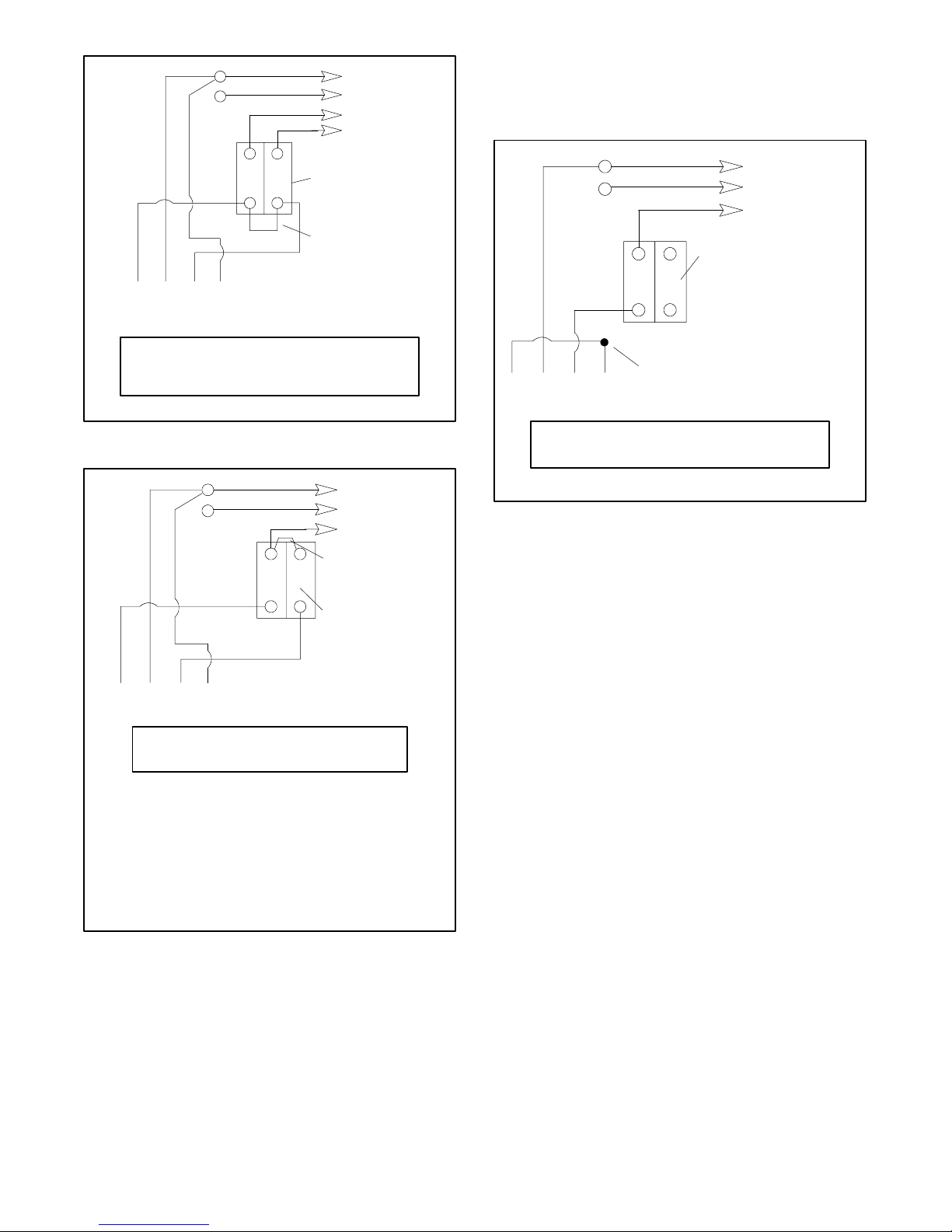
Ground
Load
Side
Line
Side
43 21
Stator Leads
LO (Neutral)
LO
GRD
L1
L2
Factory two-pole
circuit breaker
Field installed
jumper lead
220 and 240 Volt Configuration
A jumper lead is not used. After connection adjust the
voltage regulator to obtain the desired voltage.
Load
Side
Line
Side
LO (Neutral)
Ground
Factory two-pole
circuit breaker
LO
GRD
L1
L0-L1
L0-L2
60 Hz
120 volt
120 volt
50 Hz
110 volt
110 volt
TP-5867
Figure 6-16 110 and 120 Volt, 3-Wire Configurations
Ground
Load
Side
4321
Stator Leads
L0-L1
100--120 volt
LO (Neutral)
Line
Side
60 Hz
LO
GRD
L1
Field installed
jumper lead
Two-pole
circuit breaker
50 Hz
110--120 volt
Note: The existing ammeter lower scale indicates
half of the actual L1 current. DO NOT PUT
THE CT ON L1. Either label the ammeter
with a note indicating lower scale times two,
or purchase a new ammeter scaled twice the
existing ammeter and install the new
ammeter.
TP-5867
4321
Stator Leads
L0-L1
Tape to insulate
from ground
60 Hz
240 volt
50 Hz
220 volt
TP-5867
Figure 6-18 220 and 240 Volt, 2-Wire Configurations
6.10 Prestart Installation Check
Review the entire installation section. Inspect all wiring
and connections to verify that the generator set is ready
for operation. Check that there are no obstructions to
the air inlet and outlet.
Complete the startup procedure and installation
checklists supplied with the startup notification form.
Return the form to the distributor/dealer or mail it directly
to:
Kohler Power Systems
Generator Warranty Administrator
M.S. 072
Kohler, Wisconsin 53044
Figure 6-17 110 and 120 Volt, 2-Wire Configurations
TP-6049 9/02 37Section 6 Installation
Page 48

Notes
TP-6049 9/0238 Section 6 Installation
Page 49

Appendix A Abbreviations
The following list contains abbreviations that may appear in this publication.
A, amp ampere
ABDC after bottom dead center
AC alternating current
A/D analog to digital
ADC analog to digital converter
adj. adjust, adjustment
ADV advertising dimensional
AHWT anticipatory high water
AISI American Iron and Steel
ALOP anticipatory low oil pressure
alt. alternator
Al aluminum
ANSI American National Standards
AO anticipatory only
API American Petroleum Institute
approx. approximate, approximately
AR as required, as requested
AS as supplied, as stated, as
ASE American Society of Engineers
ASME American Society of
assy. assembly
ASTM American Society for Testing
ATDC after top dead center
ATS automatic transfer switch
auto. automatic
aux. auxiliary
A/V audiovisual
avg. average
AVR automatic voltage regulator
AWG American Wire Gauge
AWM appliance wiring material
bat. battery
BBDC before bottom dead center
BC battery charger, battery
BCA battery charging alternator
BCI Battery Council International
BDC before dead center
BHP brake horsepower
blk. black (paint color), block
blk. htr. block heater
BMEP brake mean effective pressure
bps bits per second
br. brass
BTDC before top dead center
Btu British thermal unit
Btu/min. British thermal units per minute
C Celsius, centigrade
cal. calorie
CARB California Air Resources Board
CB circuit breaker
cc cubic centimeter
CCA cold cranking amps
ccw. counterclockwise
CEC Canadian Electrical Code
cert. certificate, certification, certified
drawing
temperature
Institute
Institute
(formerly American Standards
Association, ASA)
suggested
Mechanical Engineers
Materials
charging
(engine)
cfh cubic feet per hour
cfm cubic feet per minute
CG center of gravity
CID cubic inch displacement
CL centerline
cm centimeter
CMOS complementary metal oxide
cogen. cogeneration
com communications (port)
coml commercial
Coml/Rec Commercial/Recreational
conn. connection
cont. continued
CPVC chlorinated polyvinyl chloride
crit. critical
CRT cathode ray tube
CSA Canadian Standards
CT current transformer
Cu copper
cu. in. cubic inch
cw. clockwise
CWC city water-cooled
cyl. cylinder
D/A digital to analog
DAC digital to analog converter
dB decibel
dBA decibel (A weighted)
DC direct current
DCR direct current resistance
deg., ° degree
dept. department
dia. diameter
DI/EO dual inlet/end outlet
DIN Deutsches Institut fur Normung
DIP dual inline package
DPDT double-pole, double-throw
DPST double-pole, single-throw
DS disconnect switch
DVR digital voltage regulator
E, emer. emergency (power source)
EDI electronic data interchange
EFR emergency frequency relay
e.g. for example (exempli gratia)
EG electronic governor
EGSA Electrical Generating Systems
EIA Electronic Industries
EI/EO end inlet/end outlet
EMI electromagnetic interference
emiss. emission
eng. engine
EPA Environmental Protection
EPS emergency power system
ER emergency relay
ES engineering special,
ESD electrostatic discharge
est. estimated
substrate (semiconductor)
Association
e. V.
(also Deutsche Industrie
Normenausschuss)
Association
Association
Agency
engineered special
E-Stop emergency stop
etc. et cetera (and so forth)
exh. exhaust
ext. external
F Fahrenheit, female
fglass. fiberglass
FHM flat head machine (screw)
fl. oz. fluid ounce
flex. flexible
freq. frequency
FS full scale
ft. foot, feet
ft. lbs. foot pounds (torque)
ft./min. feet per minute
ggram
ga. gauge (meters, wire size)
gal. gallon
gen. generator
genset generator set
GFI ground fault interrupter
GND,
gov. governor
gph gallons per hour
gpm gallons per minute
gr. grade, gross
GRD equipment ground
gr. wt. gross weight
H x W x D height by width by depth
HC hex cap
HCHT high cylinder head temperature
HD heavy duty
HET high exhaust temperature,
hex hexagon
Hg mercury (element)
HH hex head
HHC hex head cap
HP horsepower
hr. hour
HS heat shrink
hsg. housing
HVAC heating, ventilation, and air
HWT high water temperature
Hz hertz (cycles per second)
IC integrated circuit
ID inside diameter, identification
IEC International Electrotechnical
IEEE Institute of Electrical and
IMS improved motor starting
in. inch
in. H
in. Hg inches of mercury
in. lbs. inch pounds
Inc. incorporated
ind. industrial
int. internal
int./ext. internal/external
I/O input/output
IP iron pipe
ground
high engine temperature
conditioning
Commission
Electronics Engineers
O inches of water
2
TP-6049 9/02 Appendix A-1
Page 50

ISO International Organization for
Standardization
J joule
JIS Japanese Industry Standard
k kilo (1000)
K kelvin
kA kiloampere
KB kilobyte (2
kg kilogram
2
kg/cm
kgm kilogram-meter
kg/m
kilograms per square
centimeter
3
kilograms per cubic meter
10
bytes)
kHz kilohertz
kJ kilojoule
km kilometer
kOhm, kW kilo-ohm
kPa kilopascal
kph kilometers per hour
kV kilovolt
kVA kilovolt ampere
kVAR kilovolt ampere reactive
kW kilowatt
kWh kilowatt-hour
kWm kilowatt mechanical
L liter
LAN local area network
L x W x H length by width by height
lb. pound, pounds
3
lbm/ft
pounds mass per cubic feet
LCB line circuit breaker
LCD liquid crystal display
ld. shd. load shed
LED light emitting diode
Lph liters per hour
Lpm liters per minute
LOP low oil pressure
LP liquefied petroleum
LPG liquefied petroleum gas
LS left side
L
wa
sound power level, A weighted
LWL low water level
LWT low water temperature
m meter, milli (1/1000)
M mega (10
3
m
3
m
units), male
cubic meter
/min. cubic meters per minute
6
when used with SI
mA milliampere
man. manual
max. maximum
MB megabyte (2
20
bytes)
MCM one thousand circular mils
MCCB molded-case circuit breaker
meggar megohmmeter
MHz megahertz
mi. mile
mil one one-thousandth of an inch
min. minimum, minute
misc. miscellaneous
MJ megajoule
mJ millijoule
mm millimeter
mOhm, mW
milliohm
MOhm, MW
megohm
MOV metal oxide varistor
MPa megapascal
mpg miles per gallon
mph miles per hour
MS military standard
m/sec. meters per second
MTBF mean time between failure
MTBO mean time between overhauls
mtg. mounting
MW megawatt
mW milliwatt
mF microfarad
N, norm. normal (power source)
NA not available, not applicable
nat. gas natural gas
NBS National Bureau of Standards
NC normally closed
NEC National Electrical Code
NEMA National Electrical
Manufacturers Association
NFPA National Fire Protection
Association
Nm newton meter
NO normally open
no., nos. number, numbers
NPS National Pipe, Straight
NPSC National Pipe, Straight-coupling
NPT National Standard taper pipe
thread per general use
NPTF National Pipe, Taper-Fine
NR not required, normal relay
ns nanosecond
OC overcrank
OD outside diameter
OEM original equipment
manufacturer
OF overfrequency
opt. option, optional
OS oversize, overspeed
OSHA Occupational Safety and Health
Administration
OV overvoltage
oz. ounce
p., pp. page, pages
PC personal computer
PCB printed circuit board
pF picofarad
PF power factor
ph., Æ phase
PHC Phillips head crimptite (screw)
PHH Phillips hex head (screw)
PHM pan head machine (screw)
PLC programmable logic control
PMG permanent-magnet generator
pot potentiometer, potential
ppm parts per million
PROM programmable read-only
memory
psi pounds per square inch
pt. pint
PTC positive temperature coefficient
PTO power takeoff
PVC polyvinyl chloride
qt. quart, quarts
qty. quantity
R replacement (emergency)
power source
rad. radiator, radius
RAM random access memory
RDO relay driver output
ref. reference
rem. remote
Res/Coml Residential/Commercial
RFI radio frequency interference
RH round head
RHM round head machine (screw)
rly. relay
rms root mean square
rnd. round
ROM read only memory
rot. rotate, rotating
rpm revolutions per minute
RS right side
RTV room temperature vulcanization
SAE Society of Automotive
Engineers
scfm standard cubic feet per minute
SCR silicon controlled rectifier
s, sec. second
SI Systeme international d’unites,
International System of Units
SI/EO side in/end out
sil. silencer
SN serial number
SPDT single--pole, double--throw
SPST single--pole, single-- throw
spec, specs
specification(s)
sq. square
sq. cm square centimeter
sq. in. square inch
SS stainless steel
std. standard
stl. steel
tach. tachometer
TD time delay
TDC top dead center
TDEC time delay engine cooldown
TDEN time delay emergency to
normal
TDES time delay engine start
TDNE time delay normal to
emergency
TDOE time delay off to emergency
TDON time delay off to normal
temp. temperature
term. terminal
TIF telephone influence factor
TIR total indicator reading
tol. tolerance
turbo. turbocharger
typ. typical (same in multiple
locations)
UF underfrequency
UHF ultrahigh frequency
UL Underwriter’s Laboratories, Inc.
UNC unified coarse thread (was NC)
UNF unified fine thread (was NF)
univ. universal
US undersize, underspeed
UV ultraviolet, undervoltage
V volt
VAC volts alternating current
VAR voltampere reactive
VDC volts direct current
VFD vacuum fluorescent display
VGA video graphics adapter
VHF very high frequency
W watt
WCR withstand and closing rating
w/ with
w/o without
wt. weight
xfmr transformer
TP-6049 9/02A-2 Appendix
Page 51

Page 52

TP-6049 9/02f
E 1999, 2000, 2001, 2002 by Kohler Co. All rights reserved.
KOHLER CO. Kohler, Wisconsin 53044
Phone 920-565-3381, Fax 920-459-1646
For the nearest sales/service outlet in the
US and Canada, phone 1-800-544-2444
KohlerPowerSystems.com
Kohler Power Systems
Asia Pacific Headquarters
7 Jurong Pier Road
Singapore 619159
Phone (65)264-6422, Fax (65)264-6455
 Loading...