

Page 1

Operation
Industrial Generator Sets
Models:
10-1000 kW
Controller:
APM402/Decision-Makerr 3000
TP-6694 7/18j
Page 2
W ARNING: This product can expose you
to chemicals, including carbon monoxide
and benzene, which are known to the State
of California to cause cancer and birth
defects or other reproductive harm.
For more information go to
www.P65warnings.ca.gov
Product Identification Information
W ARNING: Breathing diesel engine
exhaust exposes you to chemicals known to
the State of California to cause cancer and
birth defects or other reproductive harm.
S Always start and operate the engine in
a well-ventilated area.
S If in an enclosed area, vent the exhaust
to the outside.
S Do not modify or tamper with the
exhaust system.
S Do not idle the engine except as
necessary.
For more information go to
www.P65warnings.ca.gov/diesel
Product identification numbers determine service parts.
Record the product identification numbers in the spaces
below immediately after unpacking the products so that
the numbers are readily available for future reference.
Record field-installed kit numbers after installing the
kits.
Generator Set Identification Numbers
Record the product identification numbers from the
generator set nameplate(s).
Model Designation
Specification Number
Serial Number
Accessory Number Accessory Description
Engine Identification
Record the product identification information from the
engine nameplate.
Manufacturer
Model Designation
Serial Number
Controller Identification
Record the controller description from the generator set
operation manual, spec sheet, or sales invoice. Record
the Controller Serial Number from the controller
nameplate.
Controller DescriptionAPM402/Decision-Maker
Controller Serial Number
r 3000
Firmware/Software Version Numbers
Record the version and reference numbers as shipped
from the manufacturer. Determine the Application
Program Version Number as shown in Menu 20.
Determine the Personality Profile Reference Number
from the disk supplied with the literature packet.
Application Program Version Number
Personality Profile Reference Number
User Parameter File Reference Number
Version Number Upgrades/Updates
Record the version number upgrade/updates when
installed.
Version No./Date Installed
Software Options
Record the software options.
Number and Description
Page 3

Table of Contents
Product Identification Information 2...........................................................
Safety Precautions and Instructions 7.........................................................
Introduction 13...............................................................................
Abbreviations 13...............................................................
SiteTech Software 13...........................................................
List of Related Materials 13......................................................
Service Assistance 14.........................................................................
Section 1 Specifications and Features 15......................................................
1.1 Introduction 15...........................................................
1.2 Controller Features 15....................................................
1.2.1 Switches and Controls 16..........................................
1.2.2 Annunciator Lamps 16............................................
1.2.3 Digital Display 18.................................................
1.2.4 Controller Fault Diagnostics 23.....................................
1.2.5 Digital Display Circuit Board and Connections 25.....................
1.2.6 Main Logic Circuit Board 25........................................
1.2.7 Terminal Jumper 26...............................................
1.2.8 Communication Ports 26..........................................
1.2.9 Fuses 26........................................................
1.3 Controller Logic Specifications 27...........................................
1.3.1 Status Event and Fault Specifications 27............................
1.3.2 Voltage Regulator and Calibration Specifications 33...................
1.3.3 Voltage Regulator Adjustments 33..................................
Section 2 Operation 35........................................................................
2.1 Prestart Checklist 35......................................................
2.2 Exercising Generator Set 35...............................................
2.3 Operation in Cold Weather Climates 36.....................................
2.4 Controller Operation 36...................................................
2.4.1 Starting 36.......................................................
2.4.2 Stopping (User Stopping and Fault Shutdown) 37.....................
2.4.3 Emergency Stop Switch Resetting 37...............................
2.4.4 System Status Lamps 38..........................................
2.4.5 System Fault Warning Lamp with Digital Displays 38..................
2.4.6 System Fault Shutdown Lamp With Digital Displays 40................
2.4.7 Status and Notice Digital Displays 43...............................
2.4.8 Controller Resetting (Following System Shutdown or Warning) 45.......
2.4.9 Powering Up the Engine Control Module (ECM) 45...................
2.5 Menu Displays 46........................................................
2.6 Monitoring and Programming Setup 49......................................
2.6.1 PC Communications 49...........................................
2.6.2 Modbus Communications 49.......................................
2.7 Reviewing Menu Displays 50...............................................
2.7.1 Error Messages 51...............................................
2.7.2 Overview 52.....................................................
2.7.3 Engine Metering 52...............................................
2.7.4 Generator Metering (and Calibration) 53
2.7.5 GenSet Information 54............................................
2.7.6 GenSet Run Time 54.............................................
2.7.7 GenSet System 54...............................................
2.7.8 GenSet Calibration 56.............................................
.............................
TP-6694 7/18 Table of Contents 3
Page 4

Table of Contents, continued
2.7.9 Voltage Regulator 57..............................................
2.7.10 Digital Inputs 58..................................................
2.7.11 Digital Outputs 59................................................
2.7.12 Analog Inputs 60.................................................
2.7.13 Battery Charger 1 and 2 61........................................
2.7.14 Event Log 62....................................................
2.7.15 Volt Select 62....................................................
Section 3 Scheduled Maintenance 63..........................................................
3.1 Alternator Service 63......................................................
3.2 Engine Service 63........................................................
3.3 Service Schedule 64......................................................
3.4 Alternator Bearing Service 66..............................................
3.4.1 20--300 kW Models 66............................................
3.4.2 300--1000 kW Models with 4M/5M/7M Single-Bearing Alternator 66.....
3.5 Diesel Fuel Systems 66...................................................
3.5.1 Bleeding Air from Fuel System 66..................................
3.6 Gaseous Fuel Systems 67.................................................
3.6.1 Gaseous Fuel System Concept (Single Fuel) 67......................
3.6.2 LPG Liquid Withdrawal Fuel System Concept 67.....................
3.6.3 Natural Gas and LPG Conversion 67................................
3.6.4 Fuel System Changeover Kits (Dual Fuel) 68.........................
3.7 Crankcase Ventilation (CCV) Heater Kit GM78171-KP1 68.....................
3.8 Air Cleaner Restrictor Indicator (if equipped) 70..............................
3.9 Cooling System 70.......................................................
3.9.1 Coolant Level Check 70...........................................
3.9.2 Cooling System Component Inspection 70...........................
3.9.3 Procedure to Drain Cooling System 71..............................
3.9.4 Procedure to Flush and Clean Cooling System 71....................
3.9.5 Procedure to Refill Cooling System 71..............................
3.10 Battery 72...............................................................
3.10.1 Clean Battery 73.................................................
3.10.2 Electrolyte Level Inspection 73.....................................
3.10.3 Specific Gravity Check 73.........................................
3.10.4 Charge Battery 74................................................
3.11 Storage Procedure 74.....................................................
3.11.1 Lubricating System 75............................................
3.1 1.2 Cooling System 75...............................................
3.11.3 Fuel System 75..................................................
3.1 1.4 Internal Engine Components (Gaseous-Fueled Engines) 75............
3.11.5 Exterior 75.......................................................
3.11.6 Battery 76.......................................................
Section 4 General Troubleshooting 77.........................................................
4.1 General Troubleshooting Chart 78..........................................
4.2 Controller Display and Voltage Regulation Troubleshooting Chart 81............
Section 5 Voltage Reconnection 83............................................................
5.1 Introduction 83...........................................................
5.2 Voltage Reconnection Procedure 83........................................
5.3 Voltage Reconnection Procedure 84........................................
TP-6694 7/18Table of Contents4
Page 5

Table of Contents, continued
Section 6 Accessories 89.....................................................................
6.1 Accessories and Connections 89...........................................
6.1.1 Battery Charger Kit with Alarm Option 89............................
6.1.2 Common Fault/Failure (32A) Relay Kit 90............................
6.1.3 Fifteen-Relay Dry Contact Kit 91....................................
6.1.4 Gas Fuel Valve Kit 94.............................................
6.1.5 Input/Output (I/O) Module Board 95.................................
6.1.6 Key Switch 96....................................................
6.1.7 Low Fuel (Level/Pressure) Switch 96................................
6.1.8 Manual Speed Adjust (Engine RPM Menu) 97........................
6.1.9 Prime Power Switch Kit 97.........................................
6.1.10 Remote Emergency Stop Kit 98....................................
6.1.11 Remote Reset Feature 98.........................................
6.1.12 Remote Serial Annunciator 99......................................
6.1.13 Run Relay Kit 101.................................................
6.1.14 Shunt-Trip Line Circuit Breaker 101..................................
6.2 Accessory Connections 102.................................................
Appendix A Abbreviations 107................................................................
Appendix B Programmer-Defined Settings 109.................................................
Appendix C Voltage Regulator Definitions and Adjustments 115.................................
Appendix D Alternator Protection 119..........................................................
Appendix E Controller Displays from the Engine ECM 121.......................................
TP-6694 7/18 Table of Contents 5
Page 6

Notes
TP-6694 7/186
Page 7
Safety Precautions and Instructions
IMPORTANTSAFETY INSTRUCTIONS.
Electromechanical equipment,
including generator sets, transfer
switches, switchgear, and accessories,
can cause bodily harm and pose
life-threatening danger when
improperly installed, operated, or
maintained. To prevent accidents be
aware of potential dangers and act
safely. Read and follow all safety
precautions and instructions. SAVE
THESE INSTRUCTIONS.
This manual has several types of safety
precautions and instructions: Danger,
Warning, Caution, and Notice.
DANGER
Danger indicates the presence of a
hazard that will cause severe
personal injury, death,orsubstantial
property damage.
WARNING
Warning indicates the presence of a
hazard that can cause severe
personal injury, death, or substantial
property damage.
CAUTION
Caution indicates the presence of a
hazard that will or can cause minor
personal injury or property damage.
NOTICE
Notice communicates installation,
operation, or maintenance information
that is safety related but not hazard
related.
Safety decals affixed to the equipment
in prominent places alert the operator
or service technician to potential
hazards and explain how to act safely.
The decals are shown throughout this
publication to improve operator
recognition. Replace missing or
damaged decals.
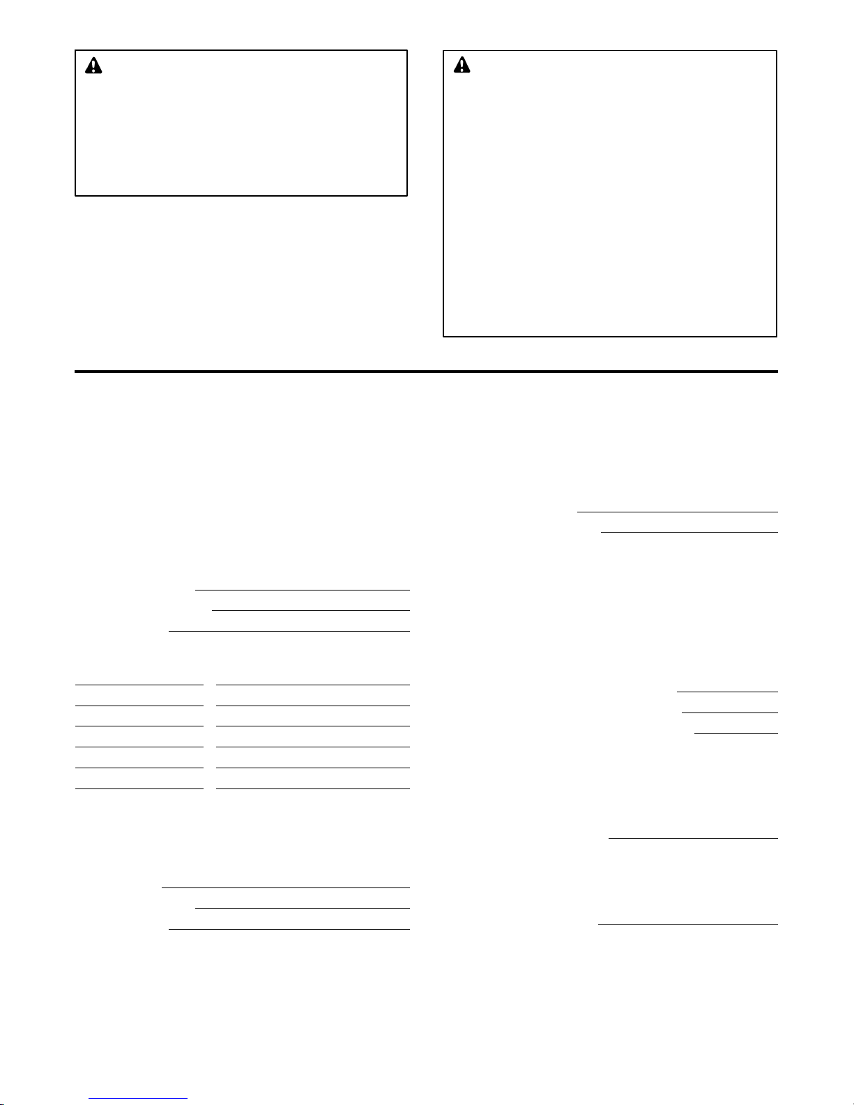
Accidental Starting
WARNING
Accidental starting.
Can cause severe injury or death.
Disconnect the battery cables before
working on the generator set.
Remove the negative (--) lead first
when disconnecting the battery.
Reconnect the negative (--) lead last
when reconnecting the battery.
Disabling the generator set.
Accidental starting can cause
severe injury or death. Before
working on the generator set or
equipment connected to the set,
disable the generator set as follows:
(1) Press the generator set off/reset
button to shut down the generator set.
(2) Disconnect the power to the battery
charger, if equipped. (3) Remove the
battery cables, negative (--) lead first.
Reconnect the negative (--) lead last
when reconnecting the battery. Follow
these precautions to prevent the
starting of the generator set by the
remote start/stop switch.
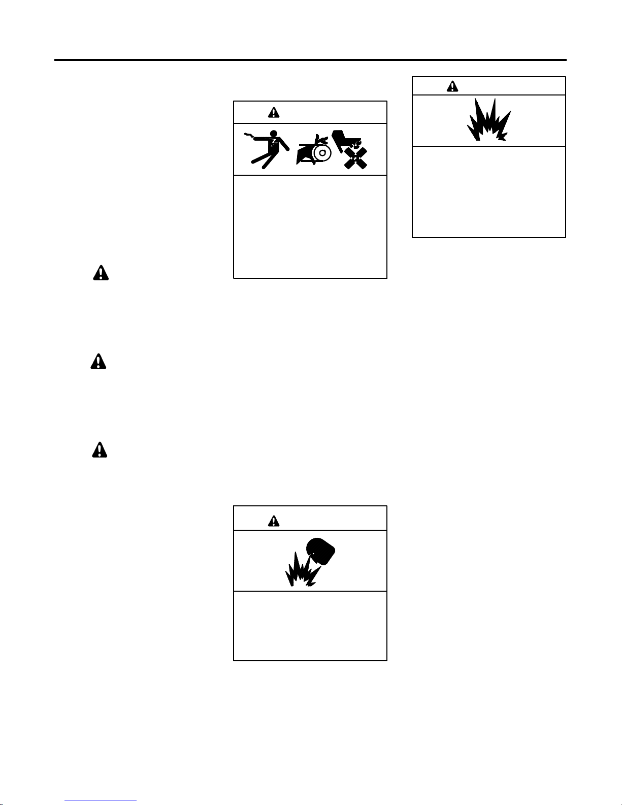
Battery
WARNING
Sulfuric acid in batteries.
Can cause severe injury or death.
Wear protective goggles and
clothing. Battery acid may cause
blindness and burn skin.
WARNING
Explosion.
Can cause severe injury or death.
Relays in the battery charger
cause arcs or sparks.
Locate the battery in a well-ventilated
area. Isolate the battery charger from
explosive fumes.
Battery electrolyte is a diluted
sulfuric acid. Battery acid can cause
severe injury or death. Battery acid
can cause blindness and burn skin.
Always wear splashproof safety
goggles, rubber gloves, and boots
when servicing the battery. Do not
open a sealed battery or mutilate the
battery case. If battery acid splashes in
the eyes or on the skin, immediately
flush the affected area for 15 minutes
with large quantities of clean water.
Seek immediate medical aid in the case
of eye contact. Never add acid to a
battery after placing the battery in
service, as this may result in hazardous
spattering of battery acid.
Battery acid cleanup. Battery acid
can cause severe injury or death.
Battery acid is electrically conductive
and corrosive. Add 500 g (1 lb.) of
bicarbonate of soda (baking soda) to a
container with 4 L (1 gal.) of water and
mix the neutralizing solution. Pour the
neutralizing solution on the spilled
battery acid and continue to add the
neutralizing solution to the spilled
battery acid until all evidence of a
chemical reaction (foaming) has
ceased. Flush the resulting liquid with
water and dry the area.
7Safety Precautions and InstructionsTP-6694 7/18
Page 8
Battery gases. Explosion can cause
severe injury or death. Battery gases
can cause an explosion. Do not smoke
or permit flames or sparks to occur near
a battery at any time, particularly when
it is charging. Do not dispose of a
battery in a fire. To prevent burns and
sparks that could cause an explosion,
avoid touching the battery terminals
with tools or other metal objects.
Remove all jewelry before servicing the
equipment. Discharge static electricity
from your body before touching
batteries by first touching a grounded
metal surface away from thebattery. To
avoid sparks, do not disturb the battery
charger connections while the battery
is charging. Always turn the battery
charger off before disconnecting the
battery connections. Ventilate the
compartments containing batteries to
prevent accumulation of explosive
gases.
Battery short circuits. Explosion
can cause severe injury or death.
Short circuits can cause bodily injury
and/or equipment damage.
Disconnect the battery before
generator set installation or
maintenance. Remove all jewelry
before servicing the equipment. Use
tools with insulated handles. Remove
the negative (--) lead first when
disconnecting the battery. Reconnect
the negative (--) lead last when
reconnecting the battery. Never
connect the negative (--) battery cable
to the positive (+) connection terminal
of the starter solenoid. Do not test the
battery condition by shorting the
terminals together.
Battery gases. Explosion can cause
severe injury or death. Incorrect use
of the equalize charge state may leadto
hazardous situations. Equalization is
ONLY applicable for flooded lead acid
(FLA) type batteries and will damage
gel, absorbed glass mat (AGM), or
nickel-cadmium (NiCad) type batteries.
In the controller menu or SiteTecht
settings, verify that the battery topology
is set correctly for the battery typeused.
Do not smoke or permit flames, sparks,
or other sources of ignition to occur
near a battery at any time.
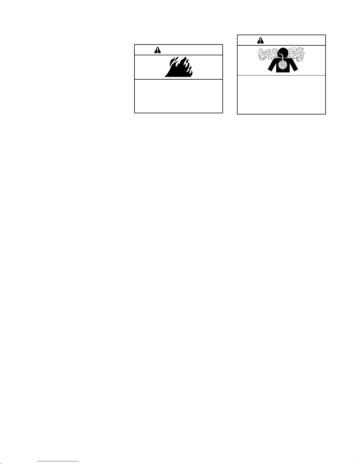
Engine Backfire/Flash
Fire
WARNING
Risk of fire.
Can cause severe injury or death.
Do not smoke or permit flames or
sparks near fuels or the fuel system.
Servicing the fuel system. A flash
fire can cause severe injury or death.
Do not smoke or permit flames or
sparks near the carburetor, fuel line,
fuel filter, fuel pump, or other potential
sources of spilled fuels or fuel vapors.
Catch fuels in an approved container
when removing the fuel line or
carburetor.
Servicing the air cleaner. A sudden
backfire can cause severe injury or
death. Do not operate the generator
set with the air cleaner removed.
Combustible materials. A fire can
cause severe injury or death.
Generator set engine fuels and fuel
vapors are flammable and explosive.
Handle these materials carefully to
minimize the risk of fire or explosion.
Equip the compartment or nearby area
with a fully charged fire extinguisher.
Select a fire extinguisher rated ABC or
BC for electrical fires or as
recommended by the local fire code or
an authorized agency. Train all
personnel on fire extinguisher
operation and fire prevention
procedures.
Exhaust System
WARNING
Carbon monoxide.
Can cause severe nausea,
fainting, or death.
The exhaust system must be
leakproof and routinely inspected.
Generator set operation. Carbon
monoxide can cause severe nausea,
fainting, or death. Carbon monoxide
is an odorless, colorless, tasteless,
nonirritating gas that can cause death if
inhaled for even a short time. Avoid
breathing exhaust fumes when working
on or near the generator set. Never
operate the generator set inside a
building unless the exhaust gas is
piped safely outside. Never operate
the generator set where exhaust gas
could accumulate and seep back inside
a potentially occupied building.
Carbon monoxide symptoms.
Carbon monoxide can cause severe
nausea, fainting, or death. Carbon
monoxide is a poisonous gas present in
exhaust gases. Carbon monoxide is an
odorless, colorless, tasteless,
nonirritating gas that can cause death if
inhaled for even a short time. Carbon
monoxide poisoning symptoms include
but are not limited to the following:
D Light-headedness, dizziness
D Physical fatigue, weakness in
joints and muscles
D Sleepiness, mental fatigue,
inability to concentrate
or speak clearly, blurred vision
D Stomachache, vomiting, nausea
If experiencing any of these symptoms
and carbon monoxide poisoning is
possible, seek fresh air immediately
and remain active. Do not sit, lie down,
or fall asleep. Alert others to the
possibility of carbon monoxide
poisoning. Seek medical attention if
the condition of affected persons does
not improve within minutes of breathing
fresh air.
8 Safety Precautions and Instructions TP-6694 7/18
Page 9

Fuel System
WARNING
Explosive fuel vapors.
Can cause severe injury or death.
Use extreme care when handling,
storing, and using fuels.
The fuel system. Explosive fuel
vapors can cause severe injury or
death. Vaporized fuels are highly
explosive. Use extreme care when
handling and storing fuels. Store fuels
in a well-ventilated area away from
spark-producing equipment and out of
the reach of children. Never add fuel to
the tank while the engine is running
because spilled fuel may ignite on
contact with hot parts or from sparks.
Do not smoke or permit flames or
sparks to occur near sources of spilled
fuel or fuel vapors. Keep the fuel lines
and connections tight and in good
condition. Do not replace flexible fuel
lines with rigid lines. Use flexible
sections to avoid fuel line breakage
caused by vibration. Do not operatethe
generator set in the presence of fuel
leaks, fuel accumulation, or sparks.
Repair fuel systems before resuming
generator set operation.
Explosive fuel vapors can cause
severe injury or death. Take
additional precautions when using the
following fuels:
Propane (LPG)—Adequate ventilation
is mandatory. Because propane is
heavier than air, install propane gas
detectors low in a room. Inspect the
detectors per the manufacturer’s
instructions.
Natural Gas—Adequate ventilation is
mandatory. Because natural gas rises,
install natural gas detectors high in a
room. Inspect the detectors per the
manufacturer’s instructions.
Fuel tanks. Explosive fuel vapors
can cause severe injury or death.
Gasoline and other volatile fuels stored
in day tanks or subbase fuel tanks can
cause an explosion. Store only diesel
fuel in tanks.
Draining the fuel system. Explosive
fuel vapors can cause severe injury
or death. Spilled fuel can cause an
explosion. Use a container to catch fuel
when draining the fuel system. Wipe up
spilled fuel after draining the system.
Gas fuel leaks. Explosive fuel
vapors can cause severe injury or
death. Fuel leakage can cause an
explosion. Check the LPG vapor or
natural gas fuel system for leakage by
using a soap and water solution with
the fuel system test pressurized to
6--8 ounces per square inch
(10--14 inches water column). Do not
use a soap solution containing either
ammonia or chlorine because both
prevent bubble formation. A successful
test depends on the ability of the
solution to bubble.
LPG liquid withdrawal fuel leaks.
Explosive fuel vapors can cause
severe injury or death. Fuel leakage
can cause an explosion. Check the
LPG liquid withdrawal fuel system for
leakage by using a soap and water
solution with the fuel system test
pressurized to at least 90 psi
(621 kPa). Do not use a soap solution
containing either ammonia or chlorine
because both prevent bubble
formation. A successful test depends
on the ability of the solution to bubble.
Hazardous Noise
CAUTION
Hazardous noise.
Can cause hearing loss.
Never operate the generator set
without a muffler or with a faulty
exhaust system.
Engine noise. Hazardous noise can
cause hearing loss. Generator sets
not equipped with sound enclosures
can produce noise levels greater than
105 dBA. Prolonged exposure to noise
levels greater than 85 dBA can cause
permanent hearing loss. Wear hearing
protection when near an operating
generator set.
Hazardous Voltage/
Moving Parts
DANGER
Hazardous voltage.
Will cause severe injury or death.
Disconnect all power sources before
opening the enclosure.
DANGER
Hazardous voltage. Moving parts.
Will cause severe injury or death.
Operate the generator set only when
all guards and electrical enclosures
areinplace.
WARNING
Hazardous voltage.
Backfeed to the utility system can
cause property damage, severe
injury, or death.
If the generator set is used for
standby power, install an automatic
transfer switch to prevent inadvertent
interconnection of standby and
normal sources of supply.
Grounding electrical equipment.
Hazardous voltage will cause severe
injury or death. Electrocution is
possible whenever electricity is
present. Ensure you comply with all
applicable codes and standards.
Electrically ground the generator set,
transfer switch, and related equipment
and electrical circuits. Turn off the main
circuit breakers of all power sources
before servicing the equipment. Never
contact electrical leads or appliances
when standing in water or on wet
ground because these conditions
increase the risk of electrocution.
9Safety Precautions and InstructionsTP-6694 7/18
Page 10
High voltage test. Hazardous
voltage will cause severe injury or
death. Follow the instructions of the
test equipment manufacturer when
performing high-voltage tests on the
rotor or stator. An improper test
procedure can damage equipment or
lead to generator set failure.
Installing the battery charger.
Hazardous voltage will cause severe
injury or death. An ungrounded
battery charger may cause electrical
shock. Connect the battery charger
enclosure to the ground of a permanent
wiring system. As an alternative, install
an equipment grounding conductor
with circuit conductors and connect it to
the equipment grounding terminal or
the lead on the battery charger . Install
the battery charger as prescribed in the
equipment manual. Install the battery
charger in compliance with local codes
and ordinances.
Connecting the battery and the
battery charger. Hazardous voltage
will cause severe injury or death.
Reconnect the battery correctly,
positive to positive and negative to
negative, to avoid electrical shock and
damage to the battery charger and
battery(ies). Have a qualified
electrician install the battery(ies).
Short circuits. Hazardous
voltage/current will cause severe
injury or death. Short circuits can
cause bodily injury and/or equipment
damage. Do not contact electrical
connections with tools or jewelry while
making adjustments or repairs.
Remove all jewelry before servicing the
equipment.
Engine block heater. Hazardous
voltage will cause severe injury or
death. The engine block heater can
cause electrical shock. Remove the
engine block heater plug from the
electrical outlet before working on the
block heater electrical connections.
Testing live electrical circuits.
Hazardous voltage or current will
cause severe injury or death. Have
trained and qualified personnel take
diagnostic measurements of live
circuits. Use adequately rated test
equipment with electrically insulated
probes and follow the instructions of the
test equipment manufacturer when
performing voltage tests. Observe the
following precautions when performing
voltage tests: (1) Remove all jewelry.
(2) Stand on a dry, approved electrically
insulated mat. (3) Do not touch the
enclosure or components inside the
enclosure. (4) Be prepared for the
system to operate automatically.
(600 volts and under)
Servicing the generator set when it
is operating. Exposed moving parts
will cause severe injury or death.
Keep hands, feet, hair, clothing, and
test leads away from the belts and
pulleys when the generator set is
running. Replace guards, screens, and
covers before operating the generator
set.
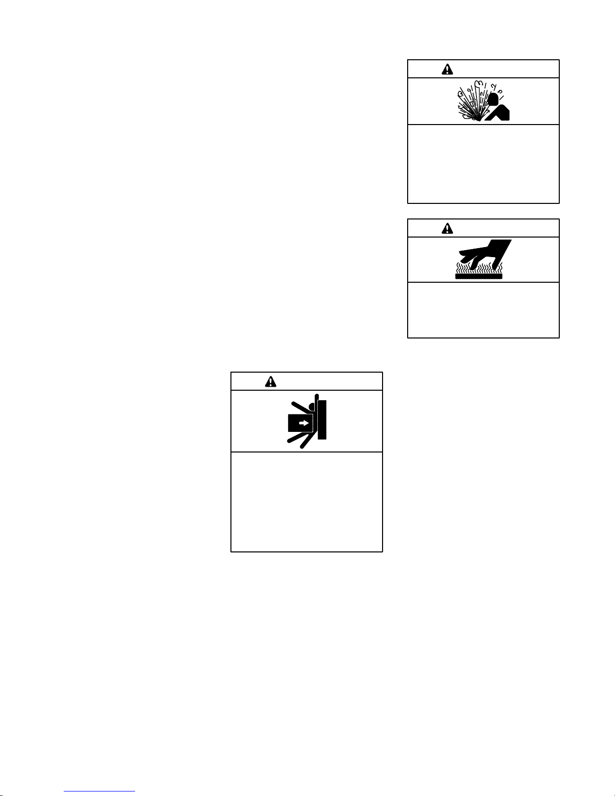
Heavy Equipment
WARNING
Unbalanced weight.
Improper lifting can cause severe
injury or death and equipment
damage.
Do not use lifting eyes.
Lift the generator set using lifting bars
inserted through the lifting holes on
the skid.
Hot Parts
WARNING
Hot coolant and steam.
Can cause severe injury or death.
Before removing the pressure cap,
stop the generator set and allow it to
cool. Then loosen the pressure cap
to relieve pressure.
WARNING
Hot engine and exhaust system.
Can cause severe injury or death.
Do not work on the generator set until
it cools.
Servicing the alternator. Hot parts
can cause severe injury or death.
Avoid touching the alternator field or
exciter armature. When shorted, the
alternator field and exciter armature
become hot enough to cause severe
burns.
Servicing the exhaust system. Hot
parts can cause severe injury or
death. Do not touch hot engine parts.
The engine and exhaust system
components become extremely hot
during operation.
Electrical backfeed to the utility.
Hazardous backfeed voltage can
cause severe injury or death. Install
a transfer switch in standby power
installations to prevent the connection
of standby and other sources of power.
Electrical backfeed into a utility
electrical system can cause severe
injury or death to utility personnel
working on power lines.
10 Safety Precautions and Instructions TP-6694 7/18
Page 11

Notice
NOTICE
This generator set has been
rewired from its nameplate voltage
to
246242
NOTICE
Voltage reconnection. Affix a notice
to the generator set after reconnecting
the set to a voltage different from the
voltage on the nameplate. Order
voltage reconnection decal 246242
from an authorized service
distributor/dealer.
NOTICE
Canadian installations only.For
standby service connect the output of
the generator set to a suitably rated
transfer switch in accordance with
Canadian Electrical Code, Part 1.
11Safety Precautions and InstructionsTP-6694 7/18
Page 12

Notes
12 Safety Precautions and Instructions TP-6694 7/18
Page 13

Introduction
This manual provides operation instructions for 10 kW
and larger generator sets equipped with the following
controllers:
D APM402 generator set controller
D Decision-Makerr 3000 generator set controller
Note: In 2018, Kohler adopted a global controller
naming convention. To support this, the name of
the Decision-Makerr 3000 controller has
transitioned to APM402. The APM402 has the
same form, fit and function as the
Decision-Makerr 3000 and supports the same
accessories.
Wiring diagram manuals are availableseparately. Refer
to the engine operation manual for generator set engine
scheduled maintenance information.
Information in this publication represents data available
at the time of print. Kohler Co. reserves the right to
change this publication and the products represented
without notice and without any obligation or liability
whatsoever.
SiteTecht Software
Several instances in this manual refer to SiteTecht
software, which can be used for programming the
APM402 or Decision-Makerr 3000 controller.
SiteTecht software is required for updating the
controller application code (firmware), loading
personality profiles, and saving or loading controller
configuration files. Contact your local distributor/dealer
for assistance.
Note: The APM402 controller uses different firmware
than the Decision-Makerr 3000 controller. Do
not attempt to load Decision-Makerr 3000
firmware on an APM402 controller, or vice-versa.
To determine the generator set controller software
version, go to the Overview menu.
List of Related Materials
Separate literature contains communication and
software information not provided in this manual.
Figure 1 lists the available literature part numbers.
Read this manual and carefully follow all procedures
and safety precautions to ensure proper equipment
operation andto avoid bodily injury. Read and follow the
Safety Precautions and Instructions section at the
beginning of this manual. Keep this manual with the
equipment for future reference.
The equipmentservice requirements are very important
to safe and efficient operation. Inspect the parts often
and perform required service atthe prescribedintervals.
Maintenance work must be performed by appropriately
skilled and suitably trained maintenance personnel
familiar with generator set operation and service.
Abbreviations
This publication makes use of numerous abbreviations.
Typically, the word(s) are spelled out along with the
abbreviation in parentheses when shown for the first
time in a section. Appendix A, Abbreviations, also
includes many abbreviation definitions.
Literature Description Literature Part No.
APM402 Controller Spec Sheet
Decision-Makerr 3000 Controller Spec
Sheet
Generator Set/Controller
Wiring Diagram Manual
Modbusr Communications Protocol
Operation Manual
SiteTecht Software Operation Manual
Remote Serial Annunciator (RSA III) TT-1625
Remote Serial Annunciator (RSA II) TT-1485
Converters, Connections, and Controller
Setup for Network Communication
G6-161
G6-100
Multiple Part Numbers
Contact your
Distributor/Dealer
TP-6113
TP-6701
TT-1405
Figure 1 Related Literature
Several engine manufacturers provide engines with
electronic controls. These electronic controls indicate
engine fault codes in addition to the generator set
controller. The engine operation and service literature
provide information for identifying engine fault codes.
For the latest literature part numbers,see therespective
Parts Catalog.
Modbusr is a registered trademark of Schneider Electric.
13IntroductionTP-6694 7/18
Page 14

Service Assistance
For professional advice on generator set power
requirements and conscientiousservice, please contact
your nearest Kohler distributor or dealer.
D Visit the Kohler Co. website at KOHLERPower.com.
D Look at the labels and decals on your Kohler product
or review the appropriate literature or documents
included with the product.
D Call toll free in the US and Canada 1-800-544-2444.
D Outside the US and Canada,call the nearest regional
office.
Headquarters Europe, Middle East, Africa
(EMEA)
Kohler EMEA Headquarters
Netherlands B.V.
Kristallaan 1
4761 ZC Zevenbergen
The Netherlands
Phone: (31) 168 331630
Fax: (31) 168 331631
Asia Pacific
Kohler Asia Pacific Headquarters
Singapore, Republic of Singapore
Phone: (65) 6264-6422
Fax: (65) 6264-6455
China
North China Regional Office, Beijing
Phone: (86) 10 6518 7950
(86) 10 6518 7951
(86) 10 6518 7952
Fax: (86) 10 6518 7955
East China Regional Office, Shanghai
Phone: (86) 21 6288 0500
Fax: (86) 21 6288 0550
India, Bangladesh, Sri Lanka
India Regional Office
Bangalore, India
Phone: (91) 80 3366208
(91) 80 3366231
Fax: (91) 80 3315972
Japan, Korea
North Asia Regional Office
Tokyo, Japan
Phone: (813) 3440-4515
Fax: (813) 3440-2727
14 Service Assistance TP-6694 7/18
Page 15
Section 1 Specifications and Features
1.1 Introduction
The spec sheets for each generator set provide modelspecific generator and engine information. The
controller spec sheet provides specifications for this
controller. Refer to the respective spec sheet for data
not supplied in this manual. Refer to the generator set
service manual, installation manual, engine operation
manual, and engine service manual for additional
specifications.
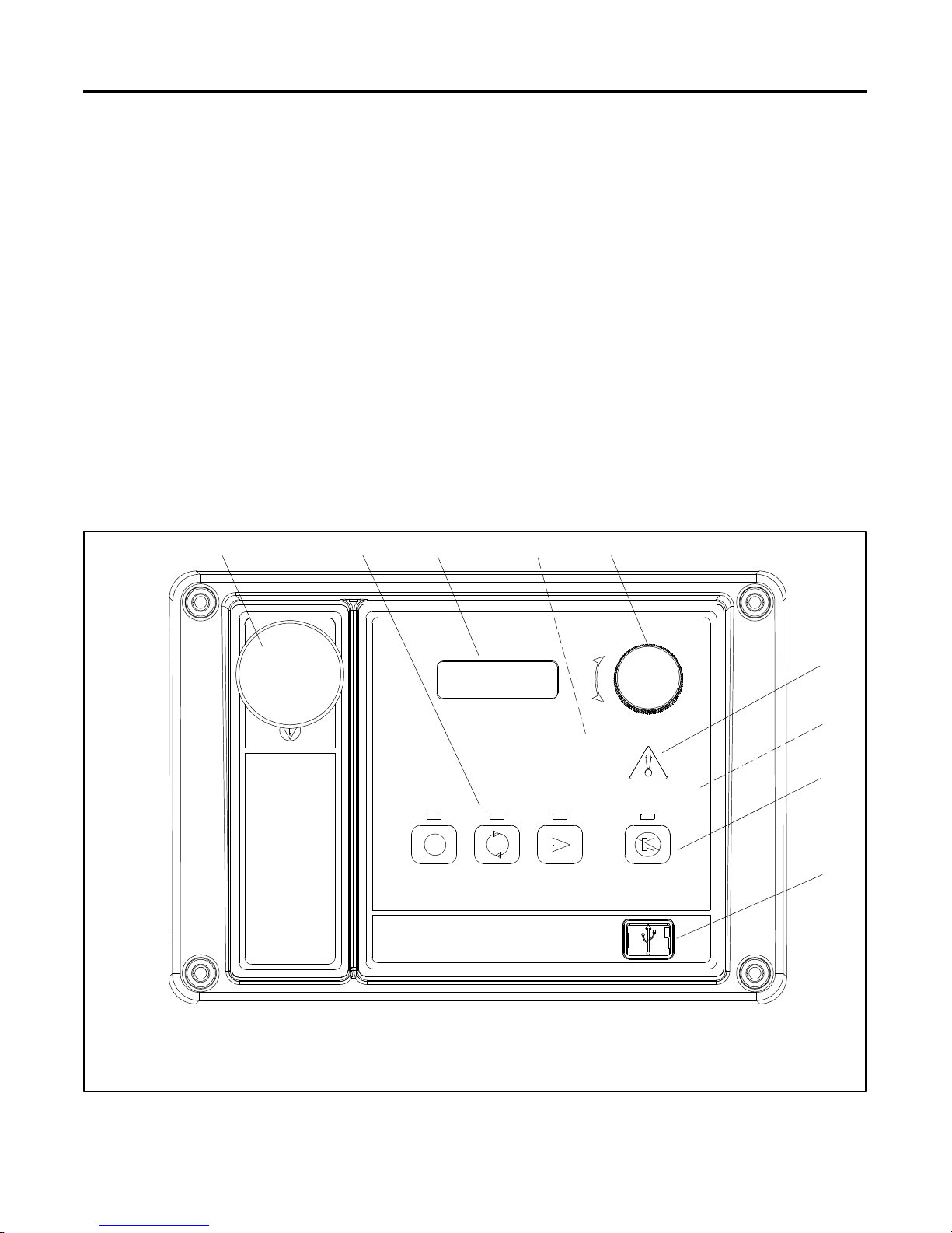
1.2 Controller Features
The controller features include the annunciator lamp,
digital display and pushbutton/rotary selector dial,
switches and controls, and fuses and terminal strip. The
following paragraphs detail the features by general
topics.
See Figure 1-1 for an illustration of the controller front
panel.
12 45
3
The controller features,accessories, and menudisplays
depend upon the engine electronic control module
(ECM) setup and features. Controller features apply to
generator set models with ECM and non-ECM engines
unless otherwise noted.
Note: Press the pushbutton/rotary selector dial to turn
on the controller lights and display. The lights and
display turn off 60 minutes after the last entry
when in the AUTO mode.
Note: After about 5 minutes of no user input
(pushbutton/rotary selector dial or buttons), the
menu is reset to the top of the main menus and
auto-paging activates for the Overview
submenus.
Note: Measurements display in metric or English units.
Use the Generator Set System menu to change
the measurement display.
OFF/RESET AUTO RUN ALARM SILENCE/
1. Emergency stop switch
2. Generator set master control switches,
OFF/RESET-- AUTO--RUN buttons with lamps
3. Digital display
4. Alarm horn (behind panel)
5. Pushbutton/rotary selector dial
6. Annunciator fault lamp
7. Controller terminal strips (on circuit board)
8. Alarm silence/lamp test button with lamp
9. Mini USB connection
Figure 1-1 Controller with Digital Display and Pushbutton/Rotary Selector Dial
FAU LT
LAMP TEST
6
7
8
9
GM65741-
TP-6694 7/18 15Section 1 Specifications and Features
Page 16

1.2.1 Switches and Controls
Note: US/Metric Display is selectable in Section
1.2.3—Digital Display—Generator Set System
Menu.
Alarm Horn. The alarm horn alerts theoperator or other
attendants that a shutdown or warning condition exists.
Alarm (Horn) Silence. The alarm silence/lamp test
switch silences the alarm horn at the operator’s
discretion. Press the master control switch AUTO
button before pressing the alarm silence/lamp test
button. The alarm horn cannot be silenced unless the
master control switch AUTO button is pressed.
Note: Additional alarm silencing options are shown in
Section 1.2.3—Digital Display—Generator Set
System Menu.
Restore alarm horn switches at all locations including
those on remote annunciator kits after correcting the
fault shutdown to avoidreactivating the alarm horn. See
Section 2—Operation, 2.4.8 Controller Resetting for
resetting the controller.
Emergency Stop. The operator-activated pushbutton
immediately shuts down the generator set inemergency
situations. Reset the emergency stop switch after
shutdown by pulling the emergency stop switch
outward. Usethe emergency stopswitch for emergency
shutdowns only. Use the master control switch
OFF/RESET button for normal shutdowns.
The pushbutton/rotary selector dial hasseveral features
and functions:
D Momentarily press the dial to activate the digital
display if dark.
D Rotate the dial to navigate through the main
menus—turn clockwise to go forward (down) and
counterclockwise to go back (up). The menus do not
wrap to the beginning.
D Press the dial at a given main menu to access the
submenus within the selected main menu.
D When in the submenu, rotate the dial to navigate
through the submenu—clockwise to go forward
(down) and counterclockwise to go back (up). The
menus do not wrap to the beginning.
D Momentarily press the dial when in the submenu to
make a user selection choice (if available) or to go
back to the respective main menu.
D Press the dial forat least3 seconds to return tothe top
of the main menus (Overview) regardless if you are in
the main menus or submenus.
D After about 5 minutes of no user input (pushbutton/
rotary selector dial or buttons), the menu resets to the
top of the main menus and auto-paging activates for
the Overview submenus.
1.2.2 Annunciator Lamps
The controller has a single annunciator fault lamp
providing visual generator set status. In addition, each
button has a corresponding lamp. See Figure 1-2.
Generator Set Master Control Switches
(OFF/RESET--AUTO--RUN). These switches reset the
controller fault lamps and start/stops the generator set.
Additional information in shown in Section 2—
Operation.
Lamp Test. Press and hold the Alarm Silence/Lamp
Test button for two seconds to test the controller
indicator lamps, alarm horn, and digital display.
Manual Speed Adjust (Engine RPM). The control
allows varying the engine speed for applications using
closed transition ATS. The user can set the nominal
running frequency slightly above or below the utility
frequency to ensure that synchronization occurs.
Additional information is shown in 2.7.7 GenSet
System. Available as a factory-installed option o r
requires a new factory personality profile.
Pushbutton/Rotary Selector Dial. This control
provides access to the menus for monitoring. Press the
selector dial to activate the digital display and to select
choices shown on the display. Rotate the dial to
navigate through the menus.
Lamp/Button Lamp Color
Alarm (Fault) Lamp Yellow (Warning) or Red (Shutdown)
Off/Reset Button Red
Auto Button Green (System Ready)
Run Button Yellow
Alarm Silence/Lamp
Test Button
Yellow
Figure 1-2 Annunciator Lamps
System Status Lamps (Master Control Switches)
The green lamp illuminates on the master controlswitch
AUTO (automatic start) button indicating the system
senses no faults and the unit is ready to start by remote
command.
The red lamp illuminates on the master control switch
OFF/RESET button indicating the generator set is
stopped.
The yellow lamp illuminates onthe master control switch
RUN button indicating the generator set is cranking or
running from a local command.
Only one of the three master control switch lamps will
illuminate at any given time.
TP-6694 7/1816 Section 1 Specifications and Features
Page 17

Alarm Silence Lamp. Yellow lamp illuminates
indicating the alarm horn was silenced.
(System) Fault Lamp. Yellow lamp illuminates
indicating a warning condition or red lamp illuminates
indicating a shutdown condition. See System Warning
Fault Lamp and System Shutdown Fault Lamp following
for system fault conditions.
System Warning Fault Lamp. Yellow lamp identifies
an existing fault condition that does not shut down the
generator set. A continuing system warning fault
condition may cause a system shutdown. Correct all
system warnings as soon as practical.
See Section 2.4.5, System Fault Warning Lamp with
Digital Displays, for definitions of the items listed. The
following conditions cause a system warning:
D AC sensing loss
D Auxiliary input (analog or digital)
D Battery charger communication loss
D Battery charger fault *
Note: Optional input sensors not required with charger
GM87448.
D Battery charger identity conflict
D Battery charger parameter mismatch
D Battery fault
D Common warning
D Critical high fuel level (diesel-powered models only) *
D Default parameters loaded
D ECM diagnostics (multiple engine inputs)
D Fuel tank leak (diesel-powered models only) *
D Ground fault *
D High battery voltage
D High coolant temperature
D High fuel level (diesel-powered models only) *
D Input/output communication loss
D Low battery voltage
D Low coolant temperature
D Low cranking voltage
D Low engine oil level *
D Low fuel (level for diesel-powered models) *
D Low fuel (pressure for gas-powered models) *
D Low oil pressure
D Not-in-auto (master control switch)
D Speed sensor fault
* Requires optional input sensors with all battery chargers except
battery charger GM87448.
System Shutdown Fault Lamp. Red lamp indicates
that the generator set has shut down because of a fault
condition. The unit will not start without resetting the
controller, see Section 2.4.8, Controller Resetting
procedure.
See Section 2.4.6, System Fault Shutdown Lamp with
Digital Displays, for definitions of the items listed. The
following conditions cause a system shutdown:
D AC sensing loss
D Alternator protection
D Auxiliary input (analog or digital)
D Common fault
D ECM address conflict
D ECM communications loss
D ECM diagnostics (multiple engine inputs)
D ECM model mismatch
D Emergency stop
D Enclosure temperature: high shutdown (available on
select Telecom units only)
D Engine over speed
D Engine under speed
D File system error (controller firmware fault)
D Fuel tank leak (diesel-powered models only) *
D High coolant temperature
D Internal failure
D kW overload
D Locked rotor (failed to crank)
D Loss of fuel
D Low coolant level *
D Low engine oil level *
D Low fuel level (diesel-powered models only) *
D Low oil pressure
D Megajector communications loss
(GM/PSI and Doosan gas-powered models only)
D Metering communication loss
D No coolant temperature signal
D No oil pressure signal
D Overcrank
D Overfrequency
D Overvoltage (each phase)
D Run relay overload
D Underfrequency
D Undervoltage (each phase)
D (Voltage) regulator communication loss
* Requires optional input sensors.
TP-6694 7/18 17Section 1 Specifications and Features
Page 18

1.2.3 Digital Display
Overview Menu
Press the pushbutton/rotary selector dial to turn on the
controller lamps and display. The lamps and display
turn off 60 minutes after the last entry.
Note: The APM402 controller takes about 5--10
seconds to power on.
The generator set must be running for some displays to
indicate values. If the generator set is not running some
values will display zero or N/A (not available).
Some displays are engine dependent, refer to the
Appendix, Controller Displays from the Engine ECM.
The 12-character, 2-line backlit heated display provides
generator set and engine data, system status, and fault
information. See Figure 1-1. The digital display shows
abbreviations in some instances, refer to 1.3.1 Status
Event and Fault Specifications for theabbreviations and
their full descriptions.
Note: US/Metric Unit Display is selectable in
Generator Set System.
Note: Display Contrast is selectable in Generator Set
System. The contrast display adjustment allows
user selected resolution values to improve digital
display clarity.
Note: After about 5 minutes of no user input
(pushbutton/rotary selector dial or buttons), the
menu resets to the top of the main menus and
auto-paging activates for the Overview
submenus.
The main menus are listed below. Within each main
menu are multiple submenus with descriptions
following.
D Overview
D Engine Metering
D Generator Metering
D GenSet Information
D GenSet Run Time
D GenSet System
D GenSet Calibration (Decision-Makerr 3000
controllers before Version 3.0.25)
D Voltage Regulation
D Digital Inputs
D Digital Outputs
D Analog Inputs
D Event Log
D Volt Select
When a new shutdown or warning fault occurs, the
auto-paging display feature activates.
Active Shutdowns display if any are present. This
alerts the user to single or multiple shutdown fault
conditions. See 1.2.2—Annunciator Lamps—System
Shutdown Fault Lamp for a list of possible shutdown
faults.
Active Warnings display if any are present. This alerts
the user to single or multiple warning fault conditions.
See 1.2.2—Annunciator Lamps—System Warning
Fault Lamp for a list of possible warning faults.
Generator Set State displays the generator set status:
D Off
D Standby
D Running
D Cooldown
D Stopping
Average Volts Line-to-Line value displays. For
three-phase configurations the average line-to-line
voltage of L1, L2, and L3 is displayed. Single-phase
configurations show the L1-L2 voltage.
Frequency (Hz) value displays for the output AC
voltage.
Current value displays as the average for three-phase
configurations or the current value for L1-L2 with
single-phase configurations.
Average kW displays. For three-phase configurations
the average line-to-line kilowatts of L1, L2, and L3 is
displayed. Single-phase configurations show the L1-L2
kilowatts.
Coolant Temperature diplays for the engine coolant
temperature.
Oil Pressure displays the engine oil pressure.
Fuel Level % displays the fuel tank level for diesel-
powered models when so equipped.
Fuel Pressure displays fuel pressurefor someengines.
Refer to the Appendix, Controller Displays from the
Engine ECM.
Battery displays the DC voltage of the engine starting
battery(ies).
CHG1 and CHG2 display battery charger voltage and
current (amps) if one or two CAN-enabled 10 Amp
battery chargers (GM87448 only) have been
connected. Shows N/A if charger GM87448 was
TP-6694 7/1818 Section 1 Specifications and Features
Page 19

connected and then removed. (DEC3000 version 4.11
or higher, and APM402)
Engine Run Time displays the total run time hours.
The calibration values are r eviewable at all times and
provide the calibration of the voltage and current
sensing logic. Changing the systemvoltage or replacing
the circuit board requires a calibration adjustment.
Software Version displays in the Overview menu. Use
the version number to determine if an upgrade is
needed and/or when troubleshooting the controller.
Engine Metering Menu
Note: The Engine Metering Menu may vary depending
upon if the selector dial is rotated clockwise or
counterclockwise.
Engine Speed (Tachometer) displays the engine
speed in RPM.
Oil Pressure displays the engine oil pressure. This
value also shows in the Overview Menu.
Coolant Temperature displays the engine coolant
temperature. This value also shows in the Overview
Menu.
Fuel Level % displays the fuel tank level for dieselpowered models if so equipped. This value also shows
in the Overview Menu.
Battery displays the DC voltage of the engine starting
battery(ies). This value also shows in the Overview
Menu.
Fuel Pressure displays fuel pressurefor someengines.
Refer to the Appendix, Controller Displays from the
Engine ECM. This value also shows in the Overview
Menu.
Generator Metering Menu
Total Power kVA and kW displays alternator output as
actual output values.
To enable calibration
, start the generator set and select
the Volts L1-L2 display. Then push and hold the
pushbutton/rotary selector dial until the Calibration
Enabled popup appears. Calibration of each display is
now available. The display will show the following
values for three-phase generator sets. Single-phase
generator sets will only display items marked (*).
D Volts L1-L2 *
D Volts L2-L3
D Volts L3-L1
D Volts L1-N *
D Volts L2-N *
D Volts L3-N
D Current L1 *
D Current L2 *
D Current L3
The user can change individual values or can select
Reset Calib?--Yes to reset all values. The Reset Calib?
display will only show if calibration is enabled. Refer to
the requirements shown with Generator Set Calibration
in 2.4.7 Status and Notice Digital Displays.
To disable calibration
, Rotate the pushbutton/rotary
selector dial until the <-- Return popup appears.
Momentarily press the pushbutton/rotary selector dial.
Stop the generator set if not already done.
Generator Set Information Menu
GenSet M/N displays the generator set model number.
GenSet S/N displays the generator set serial number.
Controller S/N displays the controller serial number.
Rated Power displays alternator output as a
percentage of the entered data value.
Volt s displays the alternator output AC voltages. The
display shows all line-to-line and line-to-neutral voltage
combinations for three-phase or single-phase
configurations.
Current displays the alternator output AC amps. The
display shows each line (L1-L2-L3) of three-phase
models or L1-L2 current for single-phase models.
Frequency (Hz) value displays for the output AC
voltage. This value also shows in the Overview Menu.
Reset Calibration providing the means to reset the
configuration values is available in this menu.
TP-6694 7/18 19Section 1 Specifications and Features
Generator Set Run Time Menu
Engine Run Time displays the total run time hours.
This value also shows in the Overview Menu.
Engine Loaded displays the total loaded hours.
Engine Starts displays the total number of generator
set startup events.
Total Ene rgy displays the total kW hours.
Page 20

Generator Set System Menu
Generator Set (Reset) Calibration Menu
The values in this menus are user-entered for the
generator set configuration and are NOT measured
values of the generator set.
Changes to the Generator Set System menu require the
use of SiteTecht software except for Measure System
and Contrast selections.
System Frequency displays the programmer-entered
L1-L2-L3 output voltage frequency for three-phase or
the L1-L2 output voltage frequency for single-phase.
System Phase displays the programmer-entered
configuration as Single Phase, Single Phase Dog Leg,
Three Phase Wye, or Three Phase Delta.
System Voltage displays the programmer-entered
L1-L2-L3 output voltage for three-phase or the L1-L2
output voltage for single-phase.
Power Rating displays the programmer entered kW
value for the generator set.
Amp Rating displays the programmer entered current
value for the generator set.
Power Type displays the programmer entered
generator set application configuration as Standby or
Prime.
Battery Voltage displays the engine electrical system
12 or 24 volts.
Measurement System displays the user selected unit
of measure as Metric or English.
Contrast displays user selected resolution values to
improve digital display clarity.
Alarm (Horn) Silence displays the programmer
selected alarm silence method as Always or Auto Only
using SiteTecht software. TheAlways selectionallows
the alarm to be silenced in any of the
OFF/RESET--AUTO--RUN modes. The Auto Only
selection allows silencing of the alarm only while in the
Auto mode.
This menu is only available in Decision-Makerr 3000
controller firmware versions before 3.0.25. On
Decision-Makerr 3000 controllers with later firmware
versions, or on APM402 controllers, go to Generator
Metering Menu—Reset Calibration.
The calibration values are r eviewable at all times and
provide the calibration of the voltage and current
sensing logic. Changing the systemvoltage or replacing
the circuit board requires a calibration adjustment. In
order to review the values when the generator set is
NOT running, enter Yes when the Enter Calib? is
displayed. The user can review the values but
attempting to change the values will cause a Cannot
calibrate error message.
If the unit is NOT running and No is entered when the
Enter Calib? is shown, the display returns to the
Generator Set Calibration main menu and entry to the
Generator Set Calibration menu is denied.
If the unit is running and Yes is entered when the Enter
Calib? is shown, the display will show the following
values for three-phase generator sets. Single-phase
generator sets will only display items marked (*).
D Volts L1-L2 *
D Volts L2-L3
D Volts L3-L1
D Volts L1-N *
D Volts L2-N *
D Volts L3-N
D Current L1 *
D Current L2 *
D Current L3
The user can change individual values or can enter Yes
when Reset all Calib? is displayed. At the end of the
Generator Set Calibration menu, Exit calibration is
shown. Press the pushbutton/rotary selector dial to exit
this menu. Refer to the requirements shown with
Generator Set Calibration in 2.4.7 Status and Notice
Digital Displays.
Note: Press the Alarm Silence/Lamp Test button to
silence the alarm horn.
Manual Speed Adjust (Engine RPM) is available as a
user selectable adjustment. The user can set the
nominal running frequency slightly above or below the
utility frequency to ensure that synchronization occurs.
Refer to 2.7.7 GenSet System for more information.
Available as a factory-installed option or requires a new
factory personality profile.
TP-6694 7/1820 Section 1 Specifications and Features
Page 21

Voltage Regulator Menu
Digital Inputs Menu
Decision-Makerr 3000 Controller firmware before
3.0.25:
The voltage regulator value is reviewable at all times. In
order to review the value when the generator set is NOT
running, enter Yes when the Enter volt reg? is displayed.
The user can review the value but attempting to change
the value will cause a Cannot edit when stopped error
message.
If the unit is NOT running and No is entered when the
Enter volt reg? is shown, the display returns to the
Voltage Regulator main menu and entry to the Voltage
Regulator menu is denied.
If the unit is running and Yes is entered when the Enter
volt reg? is shown, the display will show the value.
The usercan change the value at this time. At the endof
the Voltage Regulator menu, Exit voltage reg is
shown----press the pushbutton/rotary selector dial to exit
this menu.
Decision-Makerr 3000 Controller firmware 3.0.25 and
higher, or APM402 Controller:
The voltage regulator value is reviewable at all times
and provides the ability to fine adjust voltage. Changing
the system voltage or replacing the circuit board
typically requires a voltage adjustment.
To enable calibration
, start the generator set and select
the VR Volt Adj display. Then push and hold the
pushbutton/rotary selector dial until the Editing Enabled
popup appears. Editing of thevoltage adjustment isnow
available.
This menu allows the user to review the settings. There
are up to three digital inputs that are programmer
selectable if not reserved by factory options.
The displays for digital inputs appear as shown below
with Values true or false. Items shown in the digital
displayasTrueareactive.
D DIn A1 (digital input A1) standard
D DIn A2 (digital input A2) standard
D DIn A3 (digital input A3) standard (see note below)
D DIn B1 (digital input B1) with I/O module board
D DIn B2 (digital input B2) with I/O module board
Changes to the Digital Inputs menu requires the use of
SiteTecht software. The digitalinput caneither openor
close the circuit to activate.
Note: DIn A3 digital input is factory reserved for
Enclosure Temperature: High Shutdown on
select Telecom units.
Digital Outputs Menu
This menu allows the user to review the settings. There
is one digital output standard with the controller that is
programmer selectable. The one SPDT switch has
2 amp. contacts at 32 VDC or 0.5 amp. contacts at
120 VAC max.
There is an optional 2 input/5 output (I/O) module board
available that can provide five digital outputs. The
standard digital output on the controller is used to drive
the optional I/O Module board and becomes factory
reserved and no longer available as programmer
selectable.
The user can change the individual value or can select
Reset VR?--Yes to reset to the default value. The Reset
VR Settings display will only show if editing is enabled.
To disable calibration
, Rotate the pushbutton/rotary
selector dial until the <-- Return popup appears.
Momentarily press the pushbutton/rotary selector dial.
Stop the generator set if not already done.
The displays for digital outputs appear as shown in the
following list with Values as True or False. Items shown
in the digital display as True are active.
D DOut A1 (digital output A1) standard
D DOut B1 (digital output B1) with I/O module board
D DOut B2 (digital output B2) with I/O module board
D DOut B3 (digital output B3) with I/O module board
D DOut B4 (digital output B4) with I/O module board
D DOut B5 (digital output B5) with I/O module board
Changes to the Digital Outputs menu requires the use of
SiteTecht software. The digital output can either open
or close the circuit to activate.
TP-6694 7/18 21Section 1 Specifications and Features
Page 22

Analog Inputs Menu
Volt Select Menu
This menu allows the user to review the settings. There
is one analog input that is programmer selectable if not
reserved by factory options.
There is an optional 2 input/5 output (I/O) module board
available that can provide two additional analog inputs.
The displays for analog inputs appear as shown below
with Values of 0--5 volts.
D AIn A1 (analog input A1) standard
(reserved and not user programmable)
D AIn A2 (analog input A2) standard
D AIn B1 (analog input B1) with I/O module board
D AIn B2 (analog input B2) with I/O module board
Changes to the Analog Inputs menu requires the use of
SiteTecht software.
Event Log Menu
This menu allows the user to reviewup to1000 entries of
system events including shutdown faults, warning
faults, and status events. See 1.2.4 Controller Fault
Diagnostics for a list of the items that appear on the
Event Log.
Note: The generator set must be stopped before
changing the voltage selection.
This menu allows the user to readily change controller
voltage settings. Thevolt select feature is typically used
in towable or temporary applications.
Note: The volt select menu requires initial activation by
SiteTecht software. In SiteTecht software,
select True to activate the volt select menu.
Note: The generator set output leads require voltage
reconnection if the generator set does not have a
voltage selector switch installed.
With the generator set stopped, go to the Volt Select
menu. Then push and hold the pushbutton/rotary
selector dial until the voltage selection starts to flash.
Volt selection is now available. Scroll to the desired
voltage and momentarily press the pushbutton/rotary
selector dial to confirm the voltage selection.
The displays for Volt Select appear as shown in the
following list.
D 120/240 V 1 Ph
D 120/208 V 3 Ph
D 139/240 V 3 Ph
D 277/480 V 3 Ph
D 120/240 V 3 Ph
TP-6694 7/1822 Section 1 Specifications and Features
Page 23

1.2.4 Controller Fault Diagnostics
This table provides descriptions of the system events
and their types—warning, shutdown, status, and notice.
Warnings show yellow fault lamp and signal an
impending problem. Shutdowns show red fault lamp
and stopthe generator set. Status isan event that is not
an alert but is part of the event history. Notice is an alert
System Events Display Message List
that is NOT part of the event history. System events are
available as a Relay Output as shown.
Throughout this manual there are examples of the
display text. In some cases, the message words and
phrases are abbreviated or shortened to accommodate
the number of characters in the 12 x 2 digital display.
See the following table fora full description of thesystem
event display messages.
Warning
Description Display Message
Engine Functions
Critically high fuel level (diesel-powered models only) * Fuel Level Critically High X X
ECM communications loss ECM Comm Err Shutdwn X X
ECM diagnostics (multiple inputs) [
ECM diagnostics (multiple inputs) [
ECM faults (address conflict) ECM Addr Err Shutdwn X X
ECM faults (model mismatch) ECM Mismatch Shutdwn X X
Engine over speed Eng Speed High Shutdwn X] X
Engine start aid active Starting Aid Notice N X
Engine under speed Eng Speed Low Shutdwn X X
Fuel tank leak * Fuel Leak Warning X X
Fuel tank leak * Fuel Leak Shutdwn X X
High battery voltage Battery High Warning X X
High coolant (engine) temperature Coolnt Temp High Warning X X
High coolant (engine) temperature Coolnt Temp High Shutdwn X] X
High fuel level (diesel-powered models only) * Fuel Level High Warning X X
Loss of fuel Loss of fuel X X
Low battery voltage Battery Low Warning X X
Low coolant level * Coolant Lvl Low Shutdwn X X
Low coolant temperature Coolant Temp Low Warning X X
Low cranking voltage Lo Crank Vlt Warning X X
Low engine oil level * Oil Level Low Warning X X
Low engine oil level * Oil Level Low Shutdwn X X
Low fuel level (diesel models) * Fuel Level Low Warning X X
Low fuel level (diesel models) * Fuel Level Low Shutdwn X X
Low fuel pressure (gas models) * Fuel Press Low Warning X X
Low oil pressure Oil Press Low Warning X X
Low oil pressure Oil Press Low Shutdwn X] X
No coolant temperature signal Temp Sig Loss Shutdwn X X
No oil pressure signal Press Sig Loss Shutdwn X X
Overcrank Over Crank Shutdwn X] X
Speed sensor fault Spd Sens Flt Warning X X
ECM xxxxxx Warning X X
ECM xxxxxx Shutdwn X X
Function
Shutdown
Function
Status/
Notice
Relay
Output
TP-6694 7/18 23Section 1 Specifications and Features
Page 24

Warning
Description
General Functions
Alarm horn silenced (Alarm Silence LED only) X
Alarm silence, auto only (NFPA 110) or always AlrmSilence: Auto Only or
Aux. inputs 0--5 VDC, 1 analog
(2 additional inputs available with I/O module option)
Aux. inputs 0--5 VDC, 1 analog
(2 additional inputs available with I/O module option)
Auxiliary inputs, up to 3 digital
(2 additional inputs available with I/O module option)
Auxiliary inputs, up to 3 digital
(2 additional inputs available with I/O module option)
Backup parameters loaded Backup Pars Status S No
Battery charger 1 communication loss Bat1CommLoss X
Battery charger 2 communication loss Bat2CommLoss X
Battery charger fault * (* does not apply to charger
GM87448)
Battery charger identity conflict BatIdErr X
Battery charger parameter mismatch Param Mismatch X
Battery Fault Battery Flt X
Chicago code active Auto Locked Notice N X
Common fault (includes ])
Common warning fault Common Warng X N X
Default parameters loaded Default Pars Warning X X
Emergency stop Emerg Stop Shutdwn X] X
Enclosure temperature: high shutdown Enclsr Temp: High Shutdwn X X
Engine cooldown (delay) active Eng Cooldown Notice N X
Engine start delay active Start Delay Notice N X
Engine started Engine Start Status S X
Engine stopped Engine Stop Status S X
EPS supplying load Emerg Pwr On Notice N X
File system error (controller fault) File Error Shutdwn X X
Generator running Gen Running Notice N X
Input/output (module option board) communication loss OB1 Com Loss X X
Internal failure Intern Error Shutdwn X X
Metering communication loss MeterCommLos Shutdwn X X
NFPA 110 alarm active NFPA Alarm Notice N X
Not in auto (master switch) Not In Auto Warning X X
Remote start Remote Start Status S X
System ready System Ready Status S X
System timer failed TimerErrorNotice N X
Generator Functions
AC sensing loss AC Sens Loss Warning X X
AC sensing loss AC Sens Loss Shutdwn X X
Alternator protection Alt Protect Shutdwn X X
Ground fault input * Ground Fault Warning X X
kW overload Total Power High Shutdwn X X
Locked rotor (failed to crank) Locked Rotor Shutdwn X X
Overfrequency Freq High Shutdwn X X
Overvoltage (each phase) Volts xx--xx High Shutdwn X X
Underfrequency Frequency Low Shutdwn X X
Undervoltage (each phase) Volts xx--xx Low Shutdwn X X
(Voltage) regulator communication loss RegCommLoss Shutdwn X X
* Function requires optional input sensors or kits or is engine ECM dependent on some generator set models.
[ ECM inputs are engine manufacturer dependent.
] The Common Fault Shutdown includes the items marked X] in the Shutdown Function column.
Display Message
AlrmSilence: Always
Aux Input Warning X X
Aux Input Shutdwn X X
Aux Input Warning X X
Aux Input Shutdwn X X
Batt Chg Flt X
Common Fault Shutdwn X N X
Function
Shutdown
Function
Status/
Notice
S No
Relay
Output
X
TP-6694 7/1824 Section 1 Specifications and Features
Page 25
1.2.5 Digital Display Circuit Board and
Connections
The digital display circuit board provides:
D The backlit LCD (liquid crystal display) for monitoring
the generator set functions and output values
D Master control switches with status lights
D Fault lamp
D Pushbutton/rotary selector dial to navigate the
generator set displays
D Alarm horn and alarm silence/lamp test switch/light
D Mini USB connector for PC setup using SiteTecht
software
See Figure 1-3 for the circuit board connections.
Circuit Board Connections
P9 Connector the 24-pin connector attaches directly to
the main logic circuit board.
P10 Connector mini USB for PC upgrades located on
the front panel using SiteTecht software.
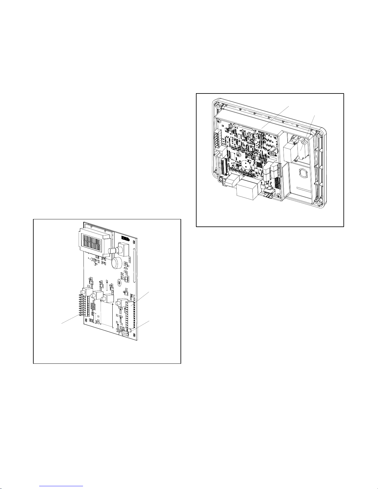
1.2.6 Main Logic Circuit Board
The main logic circuit board provides the terminal strips
and connection sockets to connect the controller to the
engine/generator, input/output connections, optional
I/O module kit, and circuit protection fuses. See
Figure 1-4 and Figure 1-5 for the circuit board
connections. See Section 6, Accessories for more
information.
1
2
P11 Connector is a 20-pin connector (not used).
1
2
3
GM65741-
1. P9 24-pin connector (opposite side) connects to main board
2. P10 5-pin mini USB connector
3. P11 20-pin connector (not used)
Figure 1-3 Digital Display Circuit Board Connectors
1. Main logic circuit board
2. Remote emergency stop switch
GM65741-
Figure 1-4 Main Circuit Board and Emergency Stop
Switch
Circuit Board Connections
P1 (24-Pin) Connector for engine/generator wiring
harness.
P2 (6-Pin) Connector for AC current.
(4) Push-on Connectors for V7/V8/V9/V0 for
generator set output voltage connection.
TP-6694 7/18 25Section 1 Specifications and Features
Page 26
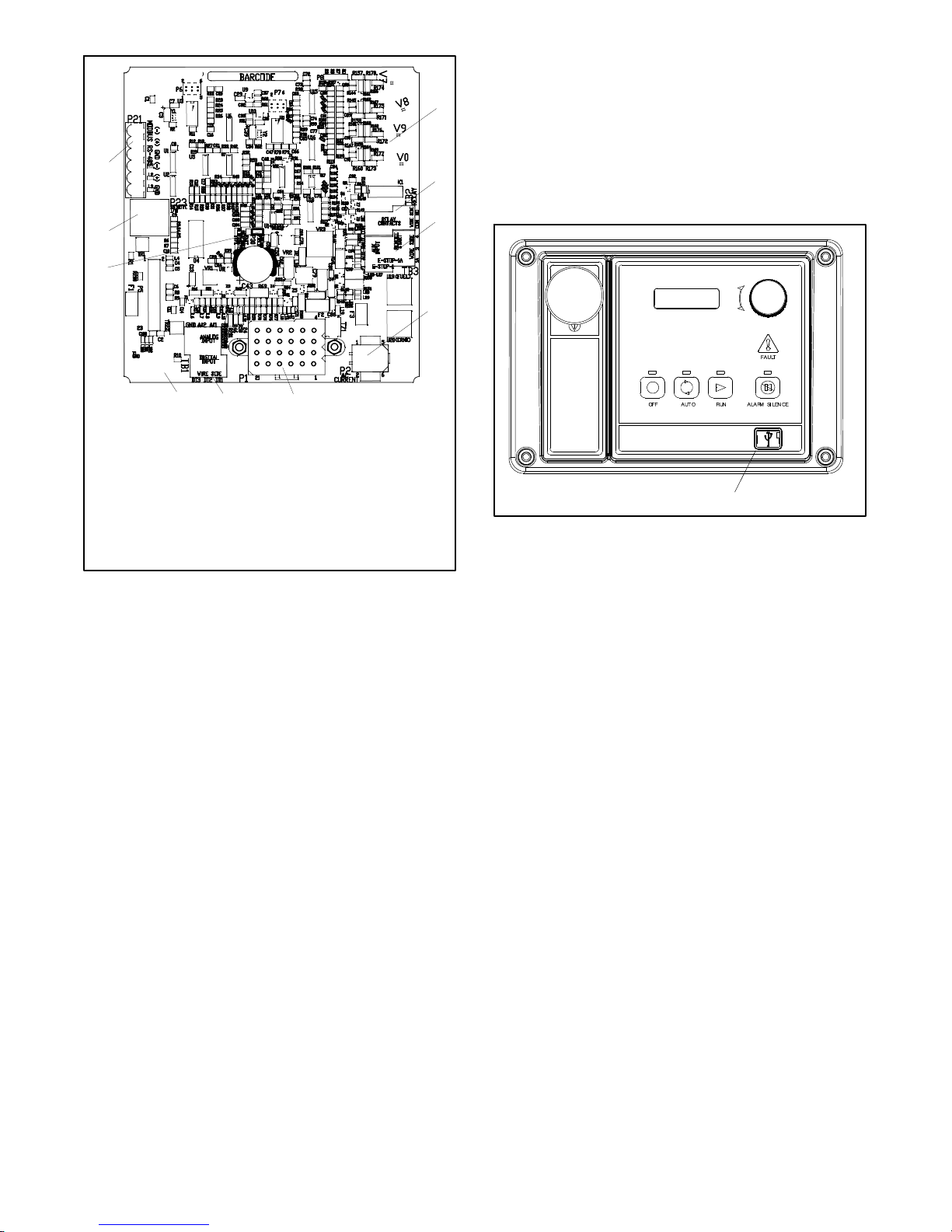
1.2.8 Communication Ports
10
9
8
7
1. (4) push-on terminal connectors
2. TB2 4-position terminal block
3. TB3 6-position terminal block
4. P2 6-pin connector
5. P1 24-pin connector
6. TB1 6-position terminal block
7. P22 3-pin connector
8. P30 jumper (Wound Field or Fast Response)
9. P23 8-pin connector (RJ45)
10. P21 6-pin connector (for RS-485 communication)
6
5
Figure 1-5 Main Circuit Board Connectors
4
GM64345-1-A
1
The main logic circuit board contains a single mini USB
communication port forPC connections, seeFigure 1-6.
For Modbusr communication using RS-485, see
Figure 1-5 (P21). Refer to the List of Related Materials
2
in the Introduction for corresponding SiteTecht
software and/orcommunication installationinformation.
3
GM65741-
1. Mini USB connection
1
Figure 1-6 Communication Port
1.2.9 Fuses
P21 (6-Pin) Connector for (RS-485) connection of
optional RSA or Modbusr communication.
P22 (3-Pin) Connector for engine ECM. Alternate CAN
connection.
P23 (8-Pin) Connector (RJ45) for optional input/output
(I/O) module circuit board.
Refer to Section 6.2, Accessory Connections for
specific connections of the following terminal block
connections.
TB1 (6-Position) Terminal Block for analog and digital
inputs.
TB2 (4-Position) Terminal Block for K1 relay outputs.
TB3 (6-Position) Terminal Block for E-stop, remote
start contacts, and aux. input connections.
1.2.7 Terminal Jumper
A circuit board P30 jumper is set based on alternator
type—Wound Field (300 kW and larger) or
Fast Response (less than 350 kW). The jumper is
factory set and needs no further adjustment. See
Figure 1-5 for location of the P30 jumper.
AC Circuit Fuses (TB5). Fuses are located inside the
generator set control box. See Figure 1-7
D 1.5-Amp (V7) fuse protects L1 sensing input to
interconnection circuit board.
D 1.5-Amp (V8) fuse protects L2 sensing input to
interconnection circuit board.
D 1.5-Amp (V9) fuse protects L3 sensing input to
interconnection circuit board.
DC Circuit Fuses are located on the controller circuit
board. See Figure 1-8.
D 1-Amp (F1) auto-resettable, fuse protects the
controller circuits.
D 1-Amp (F2) auto-resettable fuse protects the
controller circuits.
D 12-Amp (F3) non-replaceable fuse protects the
engine/starting circuitry and accessories.
Modbusr is a registered trademark of Schneider Electric.
TP-6694 7/1826 Section 1 Specifications and Features
Page 27
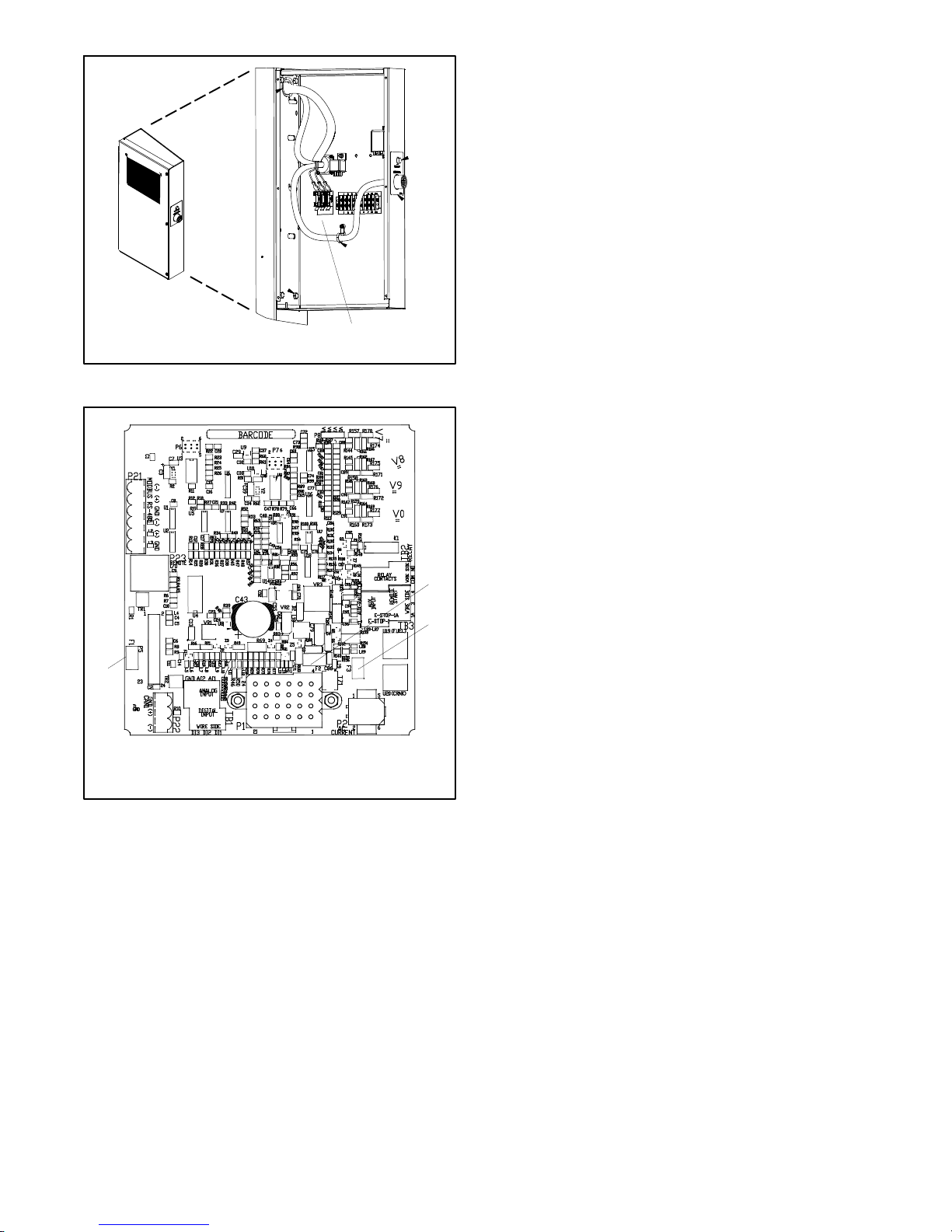
1
1. V7/V8/V9 fuses, 1.5 Amp. (qty. 3)
Figure 1-7 AC Circuit Fuses in Control Box
GM69407
1.3 Controller Logic Specifications
The controller logic specifications sectionis an overview
of the various features and functions of the controller.
Certain features function only when optional
accessories are connected. See Section 2, Operation,
for details.
The default selection time delays and digital outputs are
factory set and adjustable. Data entries require using a
PC and SiteTecht software. See the SiteTecht
software operation manual for details.
Inhibit Time Delay. The inhibit time delay is the time
period following crank disconnect during which the
generator set stabilizes and the controller does not
detect a fault or status event. Select the desired inhibit
time delay from 0 to 60 seconds.
TIme Delay (Shutdown or Warning). The time delay
follows the inhibit time delay. The time delay is the time
period between whenthe controller first detects a fault or
status event and the controller warning or shutdown
lamp illuminates. The delay prevents nuisance alarms.
Select the desired time delay from 0 to 60 seconds.
1
1. F1 1 Amp. auto-resettable
2. F2 1 Amp. auto-resettable
3. F3 12 Amp. non-replaceable
Figure 1-8 Controller DC Fuses
GM64345-C
1.3.1 Status Event and Fault
2
The Factory-Defined Settings List contains all status
3
events and faults with ranges and time delays including
items that do not have user adjustments.
Note: The engine ECM may limit the crank cycle even if
Specifications
the controller is set to a longer time period.
TP-6694 7/18 27Section 1 Specifications and Features
Page 28

Factory-Defined Settings List
Description
Controller Display
Message
Alarm
Horn
Fault
Lamp
Warning
hutdown
S
Write
Access
Display
Si
Engine Functions
Critically high fuel level
(diesel-powered models only) *
ECM communications loss ECMCommErr
ECM diagnostics (multiple
inputs) [
ECM diagnostics (multiple
inputs) [
ECM faults (address conflict) ECM Addr Err
ECM faults (model mismatch) ECM Mismatch
Engine over speed Eng Speed High
Fuel Level Critically
High
Shutdwn
On W 0--100% 95% 0--10 5
On S Fixed 10
ECM xxxxxx Warning On W
ECM xxxxxx Shutdwn On S
Shutdwn
Shutdwn
Shutdwn
On S
On S 0--255 0
On S S A 105-- 120% 115%
Engine start aid active Starting Aid Notice
Engine under speed Eng Speed Low
Shutdwn
On S S A 75--95% 85%
Fuel tank leak * Fuel Leak Warning On W
Fuel tank leak * Fuel Leak Shutdwn On S
High battery voltage Battery High Warning On W S A 110--135% 125% Fixed 10
High coolant temperature
High coolant temperature
High fuel level (diesel-powered
models only) *
Coolnt Temp High
Warning
Coolnt Temp High
Shutdwn
Fuel Level High
Warning
On W
On S
On W 0--100% 90% 0--10 5
Loss of fuel Loss of Fuel On S
Low battery voltage Battery Low Warning On W S A 80--105% 100% Fixed 90
Low coolant level * Coolant Lvl Low
Shutdwn
Low coolant temperature
Coolant Temp Low
Warning
On S Fixed 5
On W Fixed
Low cranking voltage Lo Crank Vlt Warning On W Fixed 60% Fixed 6
Low engine oil level * Oil Level Low Warning On W
Low engine oil level * Oil Level Low Shutdwn On S
Low fuel level (diesel models) * Fuel Level Low
Warning
Low fuel level (diesel models) * Fuel Level Low
Shutdwn
Low fuel pressure
(gas models) *
Fuel Press Low
Warning
On W 0--100% 35% 0--10 10
On S 0--100% 5% 0--10 0
On W
Low oil pressure
Oil Press Low Warning On W
Low oil pressure
Oil Press Low
Shutdwn
On S
* Function requires optional input sensors or is engine ECM dependent on some generator set models.
[ ECM inputs are engine-manufacturer dependent.
] Changeable only by resetting the controller with a personality profile (SiteTech 1.4 or higher).
** Denotes the default parameter range. Typically, ranges for the NiCad battery topology are slightly wider. For more details, refer to the
battery charger operation manual.
teTech
GenSet
Mode
Always
unning
R
S
topped
Range
Setting
Default
Selection
16_C
(60_F)
Time
Delay
Range
(sec.)
0--10
(0--30
inhibit)
0--10
(0--30
inhibit)
0--10
(0--30
inhibit)
Fixed
(Fixed
inhibit)
Fixed
(Fixed
inhibit)
Default
Delay
(sec.)
(5 FAA)
inhibit)
inhibit)
inhibit)
inhibit)
inhibit)
Time
0
(0
0
(0
5
(0
0
(30
5
(30
ST-- Short Term, LT--Long Term
TP-6694 7/1828 Section 1 Specifications and Features
Page 29

GenSet
Time
Default
Time
Delay
(sec.)
inhibit)
Controller Display
Description
Message
No coolant temperature signal Temp Sig Loss
Shutdwn
No oil pressure signal Press Sig Loss
Shutdwn
Overcrank
Over Crank Shutdwn On S Fixed
Write
Access
Display
teTech
Si
Mode
Always
unning
R
topped
S
Range
Setting
Default
Selection
Delay
Range
(sec.)
Alarm
Horn
Fault
Lamp
Warning
hutdown
S
On S
On S Fixed 5
Speed sensor fault Spd Sens Flt Warning On W
General Functions
Alarm silence, 0--Auto only
(NFPA 110), 1--Always
AlarmSilenceMode S A 0--1 1
Aux. inputs 0--5 VDC, 1 analog Aux Input Warning On W 0--100% 100% 0--10 0
Aux. inputs 0--5 VDC, 1 analog Aux Input Shutdwn On S 0--100% 100% 0--10 0
Auxiliary inputs, up to 3 digital
(2 additional digital inputs
available with I/O module
option)
Auxiliary inputs, up to 3 digital
(2 additional digital inputs
available with I/O module
option)
Aux Input Warning On W
Aux Input Shutdwn On S
0--10
(0--30
inhibit)
0--10
(0--30
inhibit)
0(0
inhibit)
0(0
inhibit)
Backup parameters loaded Backup Pars Status
Battery charger 1
communication loss
Battery charger 2
communication loss
Bat1CommLoss On W
Bat2CommLoss On W
Battery charger fault *
(does not apply to charger
Batt Chg Flt On W
GM87448)
Battery charger identity conflict BatIdErr On W
Battery charger parameter
mismatch
ParMisatch On W
Battery fault Battery Flt On W
Chicago code active * Auto Locked Notice
Common fault Common Fault
Shutdwn
On S
Common warning Common Warng On W
Default parameters loaded Default Pars Warning On W
Emergency stop Emerg Stop Shutdwn On S
Enclosure temperature: high
shutdown
Enclsr Temp: High
Shutdwn
On S Fixed Active Fixed
5(20
inhibit)
Engine cooldown (delay) active Eng Cooldown Notice
Engine start delay active Start Delay Notice
Engine started Engine Start Status
Engine stopped Engine Stop Status
EPS supplying load Emerg Pwr On Notice
File system error (controller
fault)
File Error Shutdwn On S
Generator running Gen Running Notice
Input/output (optional module
board) communication loss
OB1 Com Loss On W
Internal failure Intern Error Shutdwn On S
* Function requires optional input sensors or is engine ECM dependent on some generator set models.
[ ECM inputs are engine-manufacturer dependent.
] Changeable only by resetting the controller with a personality profile (SiteTech 1.4 or higher).
** Denotes the default parameter range. Typically, ranges for the NiCad battery topology are slightly wider. For more details, refer to the
battery charger operation manual.
(30
ST-- Short Term, LT--Long Term
TP-6694 7/18 29Section 1 Specifications and Features
Page 30
GenSet
Time
Default
Time
Delay
(sec.)
Controller Display
Description
Measurement Units,
0--English, 1--Metric
Message
Measurement Display DS A 0--1 1
Metering communication loss MeterCommLos
Shutdwn
Alarm
Horn
On S
Fault
Lamp
Warning
hutdown
S
Write
Access
Display
teTech
Si
Mode
Always
unning
R
topped
S
Range
Setting
Default
Selection
Delay
Range
(sec.)
NFPA 110 alarm active NFPA Alarm Notice
Not in auto (master control
buttons)
Prime power application,
0-- Standby, 1--Prime
Not In Auto Warning On W
Power Type DS A 0--1 0
Remote start Remote Start Status
System ready System Ready Status
System timer failed TimerErrorNotice
Generator Functions
AC sensing loss AC Sens Loss
Warning
AC sensing loss AC Sens Loss
Shutdwn
On W
On S Fixed 3
Alternator protection Alt Protect Shutdwn On S
Ground fault input * Ground Fault Warning On W
kW overload
Total Power High
Shutdwn
On S Fixed
102%
standby,
112%
Fixed 60
prime
Locked rotor (failed to crank) Locked Rotor Shutdwn On S S A 1--5 5
Overfrequency Freq High Shutdwn On S 102--140% 110% Fixed 10
Overvoltage (each phase) Volts (L1--L2, L2--L3,
or L3-- L1) High
On S S A 105-- 135% 120% 2--10 2
Shutdwn
Power rating Pwr Rating DS S 10--5000 275
System frequency System Freq DS S 50--60 60
System voltage System Volt DS S 110--600 208
Underfrequency Frequency Low
Shutdwn
On S 80--95% 90% Fixed
10 ST
60 LT
Undervoltage (each phase) Volts (L1--L2, L2--L3,
or L3-- L1) Low
On S S A 70--95% 80% 5--30 10
Shutdwn
Voltage/phase configuration,
0--Single phase, 1--Single
phase dogleg, 2--three phase
SystemPhase DS S 0--3 2
wye, 3--three phase delta
Voltage regulator average
voltage adjustment
(Voltage) regulator
communication loss
VR Volt Adj DS R 108--600 208
RegCommLoss
Shutdwn
On S
SiteTech Read/Write Display Only
Charger Absorption Current
Termination Target (A)
S A 1–5 2
Charger Automatic Equalize
Enable
Note: Equalize is only
available with FLA/VRLA
S A
Active
Inactive
Inactive
topology selected.
* Function requires optional input sensors or is engine ECM dependent on some generator set models.
[ ECM inputs are engine-manufacturer dependent.
] Changeable only by resetting the controller with a personality profile (SiteTech 1.4 or higher).
** Denotes the default parameter range. Typically, ranges for the NiCad battery topology are slightly wider. For more details, refer to the
battery charger operation manual.
ST-- Short Term, LT--Long Term
TP-6694 7/1830 Section 1 Specifications and Features
Page 31

Write
Access
Display
teTech
Si
Mode
Always
unning
R
topped
S
Range
Setting
Default
Selection
Time
Delay
Range
(sec.)
Description
Controller Display
Message
Alarm
Horn
Fault
Lamp
Warning
hutdown
S
Charger Charge Cycles
Between Auto Equalize Cycles
GenSet
Note: Equalize is only
S A 0–99
available with FLA/VRLA
topology selected.
Charger Custom Profile Enable
Charger Depleted Battery
Current Limit
Charger Depleted Battery
Voltage Target
S A
S A 1–5 2
S A
Active
Inactive
4–12
(12 V)
18–24
(24 V)
Inactive
10
(12 V)
20
(24 V)
Charger Equalize Stage
Duration (Min)
Note: Equalize is only
S A 60 – 480
available with FLA/VRLA
topology selected.
Charger Manual Equalize
Cycle Activation
Note: Equalize is only
available with FLA/VRLA
S A
Active
Inactive
Inactive
topology selected.
Charger Maximum Absorption
Time Threshold (Min.)
S A
60 – 360
60 – 600
(NiCad
240
only)
Charger Maximum Bulk Time
Threshold (Min)
Charger Refresh Charge Cycle
Time (Hr)
Charger Return To Bulk State
Voltage Threshold (V)
S A 60 – 600 480
S A
S A
0,
23 – 672
10–13
(12 V)**
20–26
(24 V)**
335
12.8
(12 V)
25.6
(24 V)
Charger Starter Battery
Topology
Note: Verify that the battery
topology is set correctly for the
battery type that is used.
Incorrect charger output
system voltage may cause
irreversible damage to the
S A
Default
FLA/VRLA
AGM
Gel
NiCad
Default
battery and abnormal out
gassing.
Charger System Battery
Voltage
Note: Verify that the system
voltage is set correctly for the
battery type that is used.
Incorrect charger output
system voltage may cause
S A
System 12
VDC
System 24
VDC
12 VDC
irreversible damage to the
battery and abnormal out
gassing.
* Function requires optional input sensors or is engine ECM dependent on some generator set models.
[ ECM inputs are engine-manufacturer dependent.
] Changeable only by resetting the controller with a personality profile (SiteTech 1.4 or higher).
** Denotes the default parameter range. Typically, ranges for the NiCad battery topology are slightly wider. For more details, refer to the
battery charger operation manual.
Default
Time
Delay
(sec.)
ST-- Short Term, LT--Long Term
TP-6694 7/18 31Section 1 Specifications and Features
Page 32

GenSet
Time
Default
Time
Delay
(sec.)
Description
Charger Temperature
Compensation Enable
Charger Temperature
Compensation Slope
(mV/ C)
Charger Voltage Absorption
(V)
Charger Voltage Bulk (V)
Charger Voltage Equalize (V)
Note: Equalize is only
available with FLA/VRLA
topology selected.
Charger Voltage Float (V)
Current transformer ratio ]
Controller Display
Message
Alarm
Horn
Fault
Lamp
Warning
hutdown
S
Write
Access
Display
teTech
Si
Mode
Always
unning
R
topped
S
S A
Range
Setting
Active
Inactive
--40–0
S A
(12 V)
-80–0
(24 V)
13–15
S A
(12 V)**
26–30
(24 V)**
13–15
S A
(12 V)**
26–30
(24 V)**
14–16
S A
(12 V)
28–32
(24 V)
13–14
S A
(12 V)**
26–28
(24 V)**
S S 1-- 1200
Default
Selection
Inactive
-30
(12 V)
-- 6 0
(24 V)
14.25
(12 V)
28.5
(24 V)
14.25
(12 V)
28.5
(24 V)
13.25
(12 V)
26.5
(24 V)
Delay
Range
(sec.)
ECM power S S 0--1 0
Engine cooldown delay S A 0--600 300
Engine (cyclic) crank on S A 10--30 15
Engine (cyclic) crank pause S A 1--60 15
Engine ECM start delay S A 0--300 0
Engine idle duration S A 0--60 60
Engine no. of (cyclic) crank
cycles
S S 1--6 3
Engine restart delay S A 1--10 10
Engine start aid delay S A 0--10 0
Engine start delay S A 0--300 0
Equalize Current Limit (A)
Note: Equalize is only
available with FLA/VRLA
S A 1–5
topology selected.
Forced Charge Cycle Reset
S A
Active
Inactive
Inactive
Output Enable Fixed Active
System battery voltage ]
S S 12--24 12
Voltage regulator gain S R 1--255 128
Voltage regulator stability
adjust
Voltage regulator, volts per
Hertz slope
Voltage regulator, volts per
Hertz cut in frequency
S R 1--255 128
S R 1--10 5
S R 42--62 57.5
* Function requires optional input sensors or is engine ECM dependent on some generator set models.
[ ECM inputs are engine-manufacturer dependent.
] Changeable only by resetting the controller with a personality profile (SiteTech 1.4 or higher).
** Denotes the default parameter range. Typically, ranges for the NiCad battery topology are slightly wider. For more details, refer to the
battery charger operation manual.
ST-- Short Term, LT--Long Term
TP-6694 7/1832 Section 1 Specifications and Features
Page 33

1.3.2 Voltage Regulator and Calibration
Specifications
The controller has a voltage regulation function that is
internal to the processor. This means that no external
voltage regulator is necessary. The voltage regulation
of the controller uses root mean square (rms) sensing
for fast response to changes in indicated and regulated
voltages resulting in excellent regulation accuracy.
1.3.3 Voltage Regulator Adjustments
The descriptions of the voltage regulator adjustments
and features follow. Refer to the Factory-Defined
Settings List shown in 1.3.1 for voltage regulator
adjustments. See Appendix C, Voltage Regulator
Definitions and Adjustments, for additional information
and to customize adjustments for specific applications.
Voltage Adjustment. The voltage adjustment allows
the user to enter the desired generator set output level.
This regulated level setting is the average of the three
line-to-line voltages in three-phase configurations or
L1-to-L2 in single phase configurations.
Submenus display the individual line-to-line voltages.
These voltages are for reference only and are relevant
in unbalanced load conditions. The voltage adjust
setpoint can be changed to accommodate an important
phase in an unbalanced system.
Underfrequency Unload Frequency Setpoint. This
adjustment affects the voltage droop (voltsper Hz) when
load is applied and underfrequency occurs. The
underfrequency unload setting defines the
where underfrequency starts
setpoint causes the voltage to drop thus reducing the
load allowing the engine speed to recover according to
the underfrequency unload slope setting.
Engine speed recovery depends upon characteristics
such as engine make, fuel type, load types, and
operating conditions. The underfrequency unload
setting should match the engine speed recovery
characteristics for the application.
Underfrequency Unload Slope. This setting
determines how much the voltage drops during an
underfrequency condition. Typically, applying a large
electrical load causes a dip in engine speed and
frequency. The voltage regulator reduces voltage,
allowing engine speed recovery. The volts-per-Hz
setting determines the amount of voltage drop
Regulator Gain. Regulator gain refers to thegain ofthe
control system. Generally, the higher the gain the faster
the system responds to changes and the lower the gain,
the more stable the system.
If the voltage is slow to recover when loads are applied
or removed,increase the regulator gain. If the voltage is
unstable, decrease the regulator gain.
. Any frequency below the
setpoint
.
TP-6694 7/18 33Section 1 Specifications and Features
Page 34

Notes
TP-6694 7/1834 Section 1 Specifications and Features
Page 35

Section 2 Operation
2.1 Prestart Checklist
To ensure continued satisfactory operation, perform the
following checks or inspections before or at each
startup, as designated, and at the intervals specified in
the service schedule. In addition, some checks require
verification after the unit starts.
DANGER
Hazardous voltage. Moving parts.
Will cause severe injury or death.
Operate the generator set only when
all guards and electrical enclosures
areinplace.
Air Cleaner. Check for a clean and installed air cleaner
element to prevent unfiltered air from entering engine.
Air Inlets. Check for clean and unobstructed air inlets.
Battery. Check for tight battery connections. Consult
the battery manufacturer’s instructions regarding
battery care and maintenance.
D Check for loose, corroded, or missing clamps and
hangers. Tighten or replace the exhaust clamps
and/or hangers as needed.
D Check that the exhaust outlet is unobstructed.
D Visually inspect for exhaust leaks (blowby). Check
for carbon or soot residue on exhaust components.
Carbon and soot residue indicates an exhaust leak.
Seal leaks as needed.
Fuel Level. Check the fuel level and keep the tank(s)
full to ensure adequate fuel supply.
Oil Level. Maintain the oil level at or near, not over, the
full mark on the dipstick.
Operating Area. Check for obstructions that could
block the flow of cooling air. Keep the air intake area
clean. Do not leave rags, tools, or debris on or near the
generator set.
2.2 Exercising Generator Set
DANGER
Coolant Level. Check the coolantlevel according tothe
cooling system maintenance information.
Note: Block Heater Damage. The block heater will fail
if the energized heater element is not immersed
in coolant. Fill the cooling system before turning
on the block heater. Run the engine until it is
warm, and refill the radiator to purge the air from
the system before energizing the block heater.
Drive Belts. Check the belt condition and tension of the
radiator fan, water pump, and battery charging
alternator belt(s) according to the drive belt system
maintenance information.
Exhaust System. Check for exhaust leaks and
blockages. Check the silencer and piping condition and
check for tight exhaust system connections.
Inspect the exhaust system components (exhaust
manifold, exhaust line, flexible exhaust, clamps,
silencer, and outlet pipe) for cracks, leaks, and
corrosion.
D Check for corroded or broken metalparts andreplace
them as needed.
Hazardous voltage. Moving parts.
Will cause severe injury or death.
Operate the generator set only when
all guards and electrical enclosures
areinplace.
Operate the generator set under load once each week
for one hour. Perform the exercise in the presence of an
operator when the generator set does not have an
automatic transfer switch with an exercise option.
During the exercise period, apply a minimum of 35%
load based on the nameplate standby rating, unless
otherwise instructed in the engine operation manual.
The operator should perform all of the prestart checks
before starting the manual exercise procedure. Start
the generator set according to the starting procedure in
Section 2.4, Controller Operation. While the generator
set is operating, listen for a smooth-running engine and
visually inspect generator set for fluid or exhaust leaks.
The generator set controller does not provide weekly
scheduled exercise periods. For scheduled exercise
periods, refer to the automatic transfer switch (if
equipped) literature.
TP-6694 7/18 35Section 2 Operation
Page 36

2.3 Operation in Cold Weather
Climates
Cold weather operation is generallyconsidered ambient
temperatures below freezing 0C(32F). The following
items are recommendedfor coldweather starting and/or
operation when the unit is located in an enclosure or
unheated structure. Have a licensed electrician install
120 VAC, 15 amp outlets as needed if not already in the
immediate area.
Refer to the engine operation manual regarding engine
oil viscosity, fuel composition, and coolant mixture
recommendations.
D The engine block heater is generally recommended
for most units when operated below 0C(32F) and
required as part of NFPA 110. Refer to the respective
spec sheet for temperature recommendations in
available options.
D A battery heater is generally recommended for most
units when operated below 0C(32F). Refer to the
respective spec sheet for model availability.
D An alternator strip heater is available for most
generator sets providing a heat source to prevent
moisture and frost buildup.
D The crankcase ventilation (CCV) heater kit
provides a controlled heating source to the crankcase
ventilation system preventing freezing water buildup
during cold weather. The thermostat turns on at 4_C
(40_F) and turns off at 16_C(60_F). Refer to
Section 3, Scheduled Maintenance for more
information. (Applies to 125/150 kW, 8.1 L GM- and
8.8 L PSI- powered generator set models only.)
D Heater tape is recommended when the generator set
is equipped with a closed crankcase ventilation
system and operated at or below 50% of rated load.
Wrap the UL/CSA compliant heater tape around the
crankcase canister/breather system hose that runs
from the crankcase to the air intake and use cable ties
as needed to secure the heater tape. If the heater
tape is within 152 mm (6 in.) of the exhaust system,
use thermal insulation material to protect the heater
tape.
40--60REOZK Models only. When the ambient
temperature drops below --15_C(5_F) a turbocharger
pre-lube sequence begins when the crank cycle is
initiated. During the first10 seconds of cranking, thefuel
system is disabled to ensure engine oil is present at the
turbocharger. This is necessary for the longevity of the
turbocharger on the KDI 3404TM engine. The fuel
system is then enabled for the next 5 seconds of cyclic
cranking and the engine will start as normal.
2.4 Controller Operation
The controller operation includes several types of
starting and stopping functions as detailed in the
following paragraphs. The controller master control
switch buttons, lamps, and alarm horn functions are
summarizedinFigure2-1.
2.4.1 Starting
Local Starting
Press the master control RUN button to start the
generator set at the controller.
Note: The alarm horn sounds and the Not-In-Auto
Warning display appears whenever the
generator set master control button is not in the
AUTO mode.
Generator Set
Button Mode
AUTO
OFF/RESET Off Red Yellow
RUN
(unit fails to start)
RUN
(unit starts)
* Alarm silence only works when in the Auto mode unless the Always selection is made using SiteTecht.
Refer to 2.7.7 GenSet System for more information.
Status
Off
On (or Cranking) — Off — —
Running and then
Off
Off (or Cranking)
Off Red
Off (or Cranking)
On Off Pressed Yellow
Running and then
Off
Figure 2-1 Master Control Button Function Summary
Button
Lamp
Green
Yellow
Yellow Yellow
Yellow Red
Fault Lamp
— Off — —
Red
Yellow
Alarm
Alarm Silence
Horn
On — —
Off Pressed Yellow
On — —
Off Pressed Yellow
On — —
Off Pressed Yellow
On — —
Off Pressed Yellow
On — —
On — —
Off Pressed Yellow
Button *
Alarm Silence
Lamp
Controller Display
Scrolling Overview Menu
Only
Shutdown Message
Not In Auto Warning
Not in Auto Warning
Locked Rotor Shutdown (or
other shutdown message)
Not in Auto Warming
Shutdown Message
TP-6694 7/1836 Section 2 Operation
Page 37

Note: The transient start/stop function of the controller
prevents accidental cranking of the rotating engine.
The generator set stops and recranks when the
OFF/RESET button is momentarily pressed and
then the RUN button is pressed.
The controller has a programmable cooldown timer that
functions only when the master control button is in the
AUTO mode. To stop the generator set, press the
generator set master control OFF/RESET button and
wait until the generator set comes to a complete stop.
Auto Starting
Press the master control AUTO button to allow startup
by the automatic transfer switch or remote start/stop
switch (connected to controller terminals 3 and 4).
Terminals 3 and 4 connect to a circuit that automatically
starts the generator set crank cycle when an external
source closes the circuit.
Note: The controller provides up to 30 seconds of
programmable cyclic cranking and up to
60 seconds rest with up to 6 cycles. The default
setting is 15 seconds cranking and 15 seconds
rest for 3 cycles. Make cyclic cranking
adjustments using SiteTecht software.
Prime Power Switch
The controller has an optional prime power mode of
operation. The prime power mode requires installation
of an optional prime power switch kit. See Section 6,
Accessories, for instructions on how to install the
optional prime power switch kit. Theprime power switch
kit prevents engine starting battery drain when the
generator set is shut down and no external battery
charging is available.
Move the primepower switch located on thejunction box
to the CONTROLLER ON position before attempting to
start the generator set. When the prime power mode is
off, all controller functions including the digital display,
LEDs, and alarm horn are operative.
Note: The cooldown cycle times out before the
generator set stops when a remote switch or
automatic transfer switch initiates the generator
set start/stop sequence.
Emergency Stopping
Use the controller emergency stop switch or optional
remote emergency stop for immediate shutdown.
The emergency stop switch bypasses the time delay
engine cooldown and immediately shuts down the
generator set.
Note: Use the emergency stop switch(es) for
emergency shutdowns only. Use the generator
set master control OFF/RESET button for normal
shutdowns.
The controller fault lamp lights and the unit shuts down
when the local or remote emergency stop switch
activates.
2.4.3 Emergency Stop Switch Resetting
Use the following procedure to reset the generator set
after shutdown by a local or remote emergency stop
switch. Refer to Section 2.4.8, Controller Resetting
procedure, to restart the generator set following a fault
shutdown.
1. Investigate and correct the cause of the
emergency stop.
Stop the generator set using the stopping procedures in
Section 2.4.2 before placing the generator set in the
prime power mode. Move the prime power switch
located on the junction box to the CONTROLLER OFF
position. When the generator set is is the prime power
mode, all controller functions including the digital
display, LEDs, alarm horn, and communications are
inoperative.
2.4.2 Stopping (User Stopping and
Fault Shutdown)
Normal Stopping
Run the generator set without load for 5 minutes to
ensure adequate engine cooldown.
TP-6694 7/18 37Section 2 Operation
2. Reset the optional remote emergency stop switch by
replacing the glass piece, when equipped. Additional
glass rods are available as a service part. Reset the
controller emergency stop switch by pulling the
switch dial outward.
3. Press the generator set master control
OFF/RESET button.
4. After resetting all faults using the controller reset
procedure in Section 2.4.8, press the generatorset
master control RUN or AUTO button to restart the
generator set. The generator setwill notcrank until
the reset procedure completes.
Page 38

2.4.4 System Status Lamps
The (OFF/RESET--AUTO--RUN) master controlbuttons
indicate the status condition with an integrated lamp at
the button.
AC Sensing Loss. The fault lamp illuminates yellow
and the alarm horn sounds when the controller does not
detect the nominal generatorset ACoutput voltage after
crank disconnect. The controller displaysAC Sens Loss
Warning.
The green lamp
(automatic start) button indicatingthe system senses no
faults and the unit is ready to start by remote command.
The red lamp
OFF/RESET button indicating the generator set is
stopped.
The yellow lamp
button indicating the generator setis cranking orrunning
from a local command.
Only one of the three master control button lamps will
illuminate at any given time.
illuminates on the master control AUTO
illuminates on the master control
illuminates on the master control RUN
2.4.5 System Fault Warning Lamp with
Digital Displays
The system FAULT lamp glows yellow and the alarm
horn sounds indicating a warning fault but does not shut
down the generator set. The fault lamp illuminates
yellow and the alarm horn sounds when the fuel tank
level on diesel-fueled models approaches empty. This
fault requires an optional low fuel level switch for the
lamp to function. The local display shows Fuel Level
Low Warning. See Section 2.4.8, Controller Resetting
procedure, for instructions on resetting a system
warning.
When the system warning lamp is on and no message
displays, rotate the selector dial to view messages.
When the system warning continues, it may lead to a
fault and cause a system shutdown.
Use the Silence Alarm button to silence the alarm horn
at the operator’s discretion.
If the controller is setup for a n NFPA 110 application
press the AUTO button before silencing the alarm horn.
The alarm horn cannot be silenced unless the master
control button is in the AUTO mode. See 2.4.7 Status
and Notice Digital Displays for more information.
Note: Text shown in italics in this section of the manual
represents digital display messages.
Auxiliary Input (Warning). The fault lamp illuminates
yellow and the alarm horn sounds when an auxiliary
digital or analog input signals the controller. The digital
inputs do not function during first the 30 seconds after
startup. Use SiteTecht software to define inputs as
shutdowns or warnings. The local display shows Aux
Input Warning.
Battery Charger Communication Loss. The warning
fault lamp on the controller illuminates yellow and the
alarm horn sounds when CAN communication with the
battery charger has been lost. Local display shows
either bat1CommLoss or bat2CommLoss.
Note: bat2CommLoss indicates communication loss
for battery charger number 2. bat2CommLoss is
only relevant for generator sets with more than
one battery charger.
Battery Charger Fault. The warning lamp on controller
illuminates yellow and the alarm horn sounds when the
battery charger malfunctions. Local display shows Batt
Chg Flt.
Battery Charger Identity Conflict. The warning lamp
on the controller illuminates yellow and the alarm horn
sounds when there is a CAN address communication
error. The battery charger has the same CAN address
as another generator set component. To correct a CAN
address error, verify the address identification in the
harness and power cycle the controller. Local display
shows BatIdErr.
Battery Charger Parameter Mismatch. The warning
lamp on controller illuminates yellow and the alarm horn
sounds when the battery charger metering is not in
range of the specified parameters. Local display shows
,
ParMisatch.
Battery Fault. The warning lamp on controller
illuminates yellow and the alarm horn sounds when
there is an issue with the battery such as a connection
problem or a dead battery. When the temperature
compensation sensor is connected, whether active or
inactive, and the temperature rises above 60_C (140_F)
or below --20_C(--4_F), the battery failure warning will
also be displayed indicating that the battery is unable to
take charge due to temperature. Absorption timeout will
also cause a failure since the battery was unable to
accept the expected charge in the time frame given
which indicates a potential battery issue. Local display
shows Battery Flt.
TP-6694 7/1838 Section 2 Operation
Page 39

Common Warning. The fault lamp illuminates yellow
and the alarm horn sounds when the controller is
signaled by a common warning. Use SiteTecht
software to activate the common warning. The local
display shows Common Warng. The common warning
comprises all of the warnings under a single alert.
High Coolant Temperature. The fault lamp illuminates
yellow and the alarm horn sounds when the engine
coolant temperature approaches the shutdown range.
The high coolant temperature warning does not function
during the preset inhibit time delay period after startup.
The local display shows Coolnt T emp High Warning.
Critical High Fuel Level (diesel-powered models
only). The fault lamp illuminates yellow and the alarm
horn sounds when the fuel tank level on diesel models
approaches full. This fault requires an optional critical
high fuel switch and fuel tank for the lamp to function.
The local display shows Fuel Level Critically High.
Default Parameters Loaded. The fault lamp
illuminates yellow and the alarm horn sounds when the
controller detects that the default parameter software
was loaded using SiteTecht software. The local
display shows Default Pars Warning.
ECM Diagnostics (Multiple Engine Inputs). The fault
lamp illuminates yellow and the alarm horn sounds
when ECM diagnostics signals the controller. The local
display shows ECM xxxxx Warning. The specific
display (xxxxx) will be a brief message or fault code that
is engine manufacturer dependent. The engine
literature provides the fault code description and further
information.
Fuel Tank Leak (diesel-powered models only). The
fault lamp illuminates yellow and the alarm horn sounds
when the fuel tank signals a leak of the inner tank. This
fault requires an optional fuel tank leak switch for the
lamp to function. The local display shows Fuel Leak
Warning.
Ground Fault. The fault lampilluminates yellow andthe
alarm horn sounds when a user-supplied ground fault
detector signals the controller. The local display shows
Ground Fault Warning.
High Battery Voltage. Thefault lamp illuminatesyellow
and the alarm horn sounds when the battery voltage
rises above the preset level for more than 10 seconds.
The local display shows Battery High Warning.
Figure 2-2 shows high battery voltage specifications.
The high battery voltage feature monitors the battery
and battery charging system in the generator set
operating and off modes.
Engine Electrical
System Voltage
12 13.2--16.2 15
24 26.4--32.4 30
High Battery
Voltage Range
High Battery Voltage
Default Setting
High Fuel Level (diesel-powered models only). The
fault lamp illuminates yellow and the alarm horn sounds
when the fuel tank level on diesel models approaches
near full. This fault requires an optional high fuel switch
and fuel tank for the lamp to function. The local display
shows Fuel Level High Warning.
Input/Output Communication Loss. The fault lamp
illuminates yellow and the alarm horn sounds when the
controller loses the input/output communication signal
from the optional I/O module board. The local display
shows OB1 Com Loss.
Low Battery Voltage. The fault lamp illuminates yellow
and the alarm horn sounds when the battery voltage
drops below a preset level for more than 90 seconds.
The local display shows Low Battery Warning.See
Figure 2-3 for low battery voltage specifications.
Engine Electrical
System Voltage
12 9.6-- 12.6 12
24 19.2--25.2 24
Low Battery
Voltage Range
Low Battery Voltage
Default Setting
Figure 2-3 Low Battery Voltage Specs
The low battery voltage feature monitors the battery and
battery charging system in the generator set operating
and off modes. The controller logic inhibits the low
battery voltage warning during the crank cycle.
Low Coolant Temperature. The fault lamp illuminates
yellow and the alarm horn sounds when the engine
coolant temperature is low. The low coolant
temperature warning doesnot function during the preset
inhibit time delay period after startup. The local display
shows Coolant Temp Low Warning.
Low Cranking Voltage. The fault lamp illuminates
yellow and the alarm horn sounds when the battery
voltage drops below 60% of the nominal voltage (12
VDC or 24 VDC) for more than 6 seconds during the
crank cycle. The local display shows Lo Crank Vlt
Warning.
Figure 2-2 High Battery Voltage Specs
TP-6694 7/18 39Section 2 Operation
Page 40

Low Engine Oil Level. The fault lamp illuminates
yellow and the alarm horn sounds because of low
engine oil level. This fault feature requires a n optional
low engine oil level sensorfor the lamp to function. Local
display shows Oil Level Low Warning.
Low Fuel Level (diesel-powered models only). The
fault lamp illuminates yellow and the alarm horn sounds
when the fuel tank level on diesel-fueled models
approaches empty. This fault requires an optional low
fuel level switch for the lamp to function. The local
display shows Fuel Level Low Warning.
AC Sensing Loss. The fault lamp illuminates red, the
alarm horn sounds, and the unit shuts down when the
controller does not detect the nominal generator set AC
output voltage for more than 3 seconds after crank
disconnect. The controller displays AC Sens Loss
Shutdwn.
Alternator Protection. The fault lamp illuminates red
and the unit shuts down because of an alternator
overload or short circuit. The local display shows Alt
Protect Shutdwn. See Appendix D, Alternator
Protection for more information.
Low Fuel Pressure (gas-powered models only). The
fault lamp illuminates yellow and the alarm horn sounds
when low fuel pressure on gaseous-fueled models
occurs. This fault requires an optional low fuel pressure
switch for the lamp to function. The local display shows
Fuel Press Low Warning.
Low Oil Pressure. The fault lamp illuminates yellow
and the alarm horn sounds when the engine oil pressure
approaches the shutdown range. The low oil pressure
warning does not function during first the 30 seconds
after startup. The local display shows Oil Press Low
Warning.
Not in Auto (Generator Master Control Switches).
The fault lamp illuminates yellow and the alarm horn
sounds when the generator set master control button is
in the RUN or OFF/RESET mode. The local display
shows Not In Auto Warning.
Speed Sensor Fault. The fault lamp illuminates yellow
and the alarm horn sounds when the speed signal is
absent for one second while thegenerator setruns. The
local display shows Spd Sens Flt Warning.
2.4.6 System Fault Shutdo wn Lamp
With Digital Displays
The system FAULT lamp glows red, the alarm horn
sounds, and the unit shuts down to indicate a fault
shutdown under the following conditions. See Section
2.4.8, Controller Resettingprocedure, for information on
resetting a system shutdown.
Use the Alarm Off button to silence the alarm horn at the
operator’s discretion.
If the controller is set up for an NFPA 110 application
press the AUTO button before silencing the alarm horn.
The alarm horn cannot be silenced unless the master
control button is in the AUTO mode. See 2.4.7 Status
and Notice Digital Displays for more information.
Auxiliary Input (Shutdown). The fault lamp
illuminates red, the alarm horn sounds, and the unit
shuts down when an auxiliary digital or analog inputs
signals the controller. The digital inputs do not function
during first the 30 secondsafter startup. Use SiteTecht
software to define inputs as shutdowns or warnings.
The local display shows Aux Input Shutdwn.
Common Fault. The fault lamp illuminates red, the
alarm horn sounds, and the unit shuts down when the
controller is signaled by a common fault. Use
SiteTecht software to activate the common fault
shutdown. The local display shows Common Fault
Shutdwn. The common fault comprises the following
shutdowns under a single alert.
D Emergency stop
D Engine over speed
D High coolant temperature
D Low oil pressure
D Overcrank
ECM Address Conflict. The fault lamp illuminates red,
the alarm horn sounds, and the unit shuts down when
the controller detects an error with the ECM address.
The local display shows ECMAddr Err Shutdwn.
ECM Communications Loss. The fault lamp
illuminates red, the alarm horn sounds, and the unit
shuts down when the ECM communication link is
disrupted. The local display shows ECM Comm Err
Shutdwn.
ECM Diagnostics (Multiple Engine Inputs). The fault
lamp illuminates red, the alarm horn sounds, and the
unit shuts down when ECM diagnostics signals the
controller. The local display shows ECM xxxxx
Shutdwn. The specific display (xxxxx) will be a brief
,
message or fault code that is engine manufacturer
dependent. The engine literature provides the fault
code description and further information.
Note: Text shown in italics in this section of the manual
represents digital display messages.
TP-6694 7/1840 Section 2 Operation
Page 41

ECM Model Mismatch. The fault lamp illuminates red,
the alarm horn sounds, and the unit shuts down when
the controller detects an error with the ECM model. The
local display shows ECM Mismatch Shutdwn.
Emergency Stop. The fault lamp illuminates red, the
alarm horn sounds, and the unit shuts down when the
local or optional remote emergency stop switch
activates. The local display shows Emerg Stop
Shutdwn.
Enclosure Temperature: High Shutdown (Available
on select Telecom units only). The fault lamp
illuminates red, the alarm horn sounds, and the unit
shuts down when the enclosure reaches high
temperature. The digital input does not function during
first the 20 seconds after startup and has a 5 second
delay. The local display shows Enclsr Temp: High
Shutdwn.
Engine Over Speed. The fault lamp illuminates red, the
alarm horn sounds, and the unit shuts down immediately
when the governed frequency on 50 and 60 Hz models
exceeds the over speed setting. The local display
shows Eng Speed High Shutdwn.
Engine Under Speed. The fault lamp illuminates red,
the alarm horn sounds, and the unit shuts down
immediately when the governed frequency on 50 and
60 Hz models drops belowthe under speed setting. The
local display shows Eng Speed Low Shutdwn.
File System Error. The fault lamp illuminates red, the
alarm horn sounds, and the unit shuts down when the
internal controller diagnostics detect a firmware file
error. The local display shows File Error Shutdwn.
kW Overload. The fault lamp illuminates red, the alarm
horn sounds, and the unit shuts down when the
generator set supplies more than 102% of the rated
standby output kW (or 112% of the rated prime power
output kW) for more than 60 seconds. The local display
shows Total Power High Shutdwn.
Locked Rotor (failed to crank). If none of the speed
sensing inputs show engine rotation within the preset
time delay of initiating engine cranking, the ignition and
crank circuits turn off for the preset period and the cycle
repeats. The fault lamp illuminates red, the alarm horn
sounds, and the unit shuts down after the second cycle
of the preset period ofcranking. Thelocal displayshows
Locked Rotor Shutdown.
Loss of Fuel. The fault lamp illuminates red and the
alarm horn sounds when the unit shuts down without
receiving a signal from the controller to do so. On
diesel-fueled units this condition includes fuel pump
failure, loss o f fuel prime, and/or an empty fuel tank. On
gaseous-fueled units this condition includes loss of fuel
pressure and/or an empty fuel tank. The local display
shows Loss of Fuel.
Low Coolant Level. The fault lamp illuminates red, the
alarm horn sounds, and the unit shuts down because of
low coolant level. Shutdown occurs 5 seconds after low
coolant level is detected. Local display shows Coolant
Lvl Low Shutdwn.
Low Engine Oil Level. The fault lamp illuminates red,
the alarm hornsounds, and theunit shuts downbecause
of low engine oil level. This fault feature requires an
optional low engine oil level sensor for the lamp to
function. Local display shows Oil Level Low Shutdwn.
Fuel Tank Leak (diesel-powered models only). The
fault lamp illuminates red, the alarm horn sounds, and
the unit shuts down when the fuel tank signals a leak of
the inner tank. This fault requires an optional fuel tank
leak switch for the lamp to function. The local display
shows Fuel Leak Shutdwn.
Low Fuel Level (diesel-powered models only). The
fault lamp illuminates red, the alarm horn sounds, and
the unit shuts down when the fuel tank level on
diesel-fueled models approaches empty. This fault
requires an optional low fuel level switch for the lamp to
function. The local display shows Fuel Level Low
Shutdwn.
High Coolant Temperature. The fault lamp illuminates
red, the alarm horn sounds, and the unit shuts down
because of high engine coolant temperature. The high
coolant temperature shutdown does not function during
the preset inhibit time delay period after startup. The
local display shows Coolnt Temp High Shutdwn.
Note: The high engine temperature shutdown function
and the low coolant level shutdown function are
independent. A low coolant level condition may
not activate the high engine temperature switch.
Internal Fault. The fault lamp illuminates red, the alarm
horn sounds, and the unit shuts down when the internal
diagnostics detect a controller malfunction. The local
Low Oil Pressure. The fault lamp illuminates red, the
alarm horn sounds, and the unit shuts down because of
low oil pressure. The shutdown occurs 5 seconds after
the low pressure condition is detected. The low oil
pressure shutdown does not function during first the
30 seconds after startup. The local display shows Oil
Press Low Shutdwn.
MegaJector Communications Loss (GM/PSI and
Doosan gas-powered models only). The fault lamp
illuminates red, the alarm horn sounds, and the unit
shuts down when the communication link is disrupted.
The local display shows MJ Comm Loss.
display shows Intern Error Shutdwn.
TP-6694 7/18 41Section 2 Operation
Page 42

Metering Communications Loss. The fault lamp
illuminates red, the alarm horn sounds, and the unit
shuts down when the metering to controller
communication link is disrupted. The local display
shows MeterCommLos Shutdwn.
No Coolant Temperature Signal. The fault lamp
illuminates red, the alarm horn sounds, and the unit
shuts down when the engine coolant temperature
sender circuit is open. The local display shows Temp
Sig Loss Shutdwn.
No OilPressure Signal. The fault lampilluminates red,
the alarm horn sounds, and the unit shuts down when
the engine oil pressure sender circuit is open for more
than 5 seconds. Thelocal display shows Press Sig Loss
Shutdwn.
Overcrank. The fault lamp illuminates red, the alarm
horn sounds, and cranking stops when the unit does not
start within the defined cranking period. The local
display shows Over Crank Shutdwn. See Section 2.4.1,
Auto Starting, and Section 1.3.1, Status Event and Fault
Specifications for cyclic crank specifications.
Note: The controller is equipped with an automatic
restart function. When speed drops below 25 Hz
(750 rpm) while the engine is running, the unit
attempts to recrank. The unit then follows the
cyclic cranking cycle and, whenthe engine fails to
start, will shut down on an overcrank fault
condition.
Overfrequency. The fault lamp illuminates red, the
alarm horn sounds, and the unit shuts down when the
frequency is above theoverfrequency setting. The local
display shows Freq High Shutdwn. See Figure 2-4.
Overvoltage
Setting Range
105%-- 135% of
nominal
Time Delay
Range
2--10 sec. 120% at 2 sec.
Overvoltage Default
Setting
Figure 2-5 Overvoltage Specs
Run Relay Overload. The fault lamp illuminates red,
the alarm horn sounds, and the unit shuts down when
the controller smart switch that operates generator set
wire number 70 (Run) is overloaded. The local display
shows Run Relay Overload.
Underfrequency. The fault lamp illuminates red, the
alarm horn sounds, and the unit shuts down when the
frequency drops below the underfrequency setting. The
local display shows Frequency Low Shutdwn.See
Figure 2-6 for underfrequency specifications.
Underfreq. Setting
Range
80%-- 95% of
nominal
Time Delay
10 sec. (short term) 90% of nominal
Underfrequency
Default Setting
Figure 2-6 Underfrequency Specs
Note: The long-term shutdown occurs if the frequency
is 1 Hz or more below the system frequency for
60 sec. The long-term shutdown is not
adjustable.
Undervoltage. The fault lamp illuminates red, the
alarm horn sounds, and the unit shuts down when the
voltage drops below the undervoltage setting for the
time delay period. The local display shows Volts
(L1--L2, L2--L3, or L3--L1) Low Shutdwn.See
Figure 2-7 for undervoltage specifications
Overfrequency
Setting Range
102%-- 140% of nominal 10 sec. 110% of nominal
Time Delay
Overfrequency
Default Setting
Figure 2-4 Overfrequency Specs
Overvoltage (Each Phase). The fault lamp illuminates
red, the alarm horn sounds, and the unit shuts down
when the voltage exceeds the overvoltage setting for
the preset time delay period. The local display shows
Volts (L1--L2, L2--L3, or L3--L1) High Shutdwn.See
Figure 2-5 for overvoltage specifications.
Note: Overvoltage can damage sensitive equipment in
less than one second. Install separate
overvoltage protection on online equipment
requiring faster than 2-second shutdown.
Undervoltage
Setting Range
70%-- 95% of
nominal
Time Delay Range
5--30 sec.
Undervoltage
Default Setting
80% of nominal at
10 sec.
Figure 2-7 Undervoltage Specs
(Voltage) Regulator Communications Loss. The
fault lamp illuminates red, the alarm horn sounds, and
the unit shuts down when the voltage regulator to
controller communication link is disrupted. The local
display shows RegCommLos Shutdwn.
TP-6694 7/1842 Section 2 Operation
Page 43

2.4.7 Status and Notice Digital Displays
Warnings and shutdown faults appear on the digital
display and become part of the event history. Beyond
the warnings and shutdowns there are several events
which also appear on the digital display. Status is an
event that is not an alert but is part of the event history.
Notice is an alert that is not part of the event history.
The controller allows a selected number of changes by
the user for setting up the controller application which
are covered in this section.
Engine Cooldown (Delay) Active. This notice
message indicatesthat the delay for engine cooldown is
active where the generator set will continue to run after
the OFF/RESET button is pressed. The unit will
continue to run until the time delay times out. The local
display shows Eng Cooldown Notice.
Engine Start Aid Active. This notice message
indicates that the start aid is active and will energize an
engine equipped preheat or ether system during the
crank cycle. Use SiteTecht software to set up this
feature. The local display shows Starting Aid Notice.
Note: Text shown in italics in this section of the manual
represents digital display messages.
Alarm Silence. This status message indicates whether
the alarm horn can be silenced in any button mode
(OFF/RESET--AUTO--RUN) or requires the AUTO
button be pressed first compliant per NFPA 110. Use
SiteTecht software to change this setting. See Section
2.4.8, Controller Resettingprocedure, for information on
resetting the system.
The local display shows AlrmSilence: Always when the
alarm horn can be silenced with the master control
buttons in any position (default setting).
The local display shows AlrmSilence: Auto Only when
the alarm horn can be silenced only when in the AUTO
mode.
Backup Parameters Loaded. This status message
indicates that backup parameter firmware is now loaded
on the controller using SiteTecht software. The local
display shows Backup Pars Status.
Chicago Code Active. This notice message indicates
that a pass code is required to access the controller.
Use SiteTecht software to set up the feature. The local
display shows Auto Locked Notice.
Engine Start Delay Active. This notice message
indicates that the delay for engine start is active where
the generator set will not start right after the RUN button
is pressed. The unit will start cranking after the time
delay times out. The local display shows Start Delay
Notice.
Engine Started. This status indicates that the
generator set startcircuit is closedallowing the engine to
crank and run. The local display shows Engine Start
Status.
Engine Stopped. This status indicates that the
generator set start circuit is open causing the engine to
shut down. The local display shows Engine Stop Status.
Generator Running. This notice indicates that the
generator set has started and is running. The local
display shows Gen Running Notice.
Emergency Power System (EPS) Supplying Load.
This notice message indicates when the generator set
supplies more than 1% of the rated standby output
current. The local display shows Emerg Pwr On Notice.
TP-6694 7/18 43Section 2 Operation
Page 44

Generator Set Calibration (User Defined). This
selectable display is in the GenSet Calibration Menu
allowing the user to calibrate the controller and
generator set. Use the Pushbutton/Rotary Selector Dial
to navigate and select this feature.
Changes to this display must be done withthe generator
set running. The local display shows Enter calib? No or
Yes. Select No to make no change. Select Yes to
calibrate the following values:
D VoltsL1--L2:x.xV
D VoltsL2--L3:x.xV
D VoltsL3--L1:x.xV
D Volts L1 - -N: x.x V
D Volts L2 - -N: x.x V
D Volts L3 - -N: x.x V
D Current L1: x.x A
D Current L2: x.x A
D Current L3: x.x A
The user can individually calibrate the values above or
reset all of them. The local display Reset all calib? No or
Yes. Select No to make no changes and exit GenSet
Calibration. Select Yes to reset all of the values.
When calibrating voltage, the metered value and the
number being entered as the calibrated value must be
within 10% of the system operating voltage.
NFPA 110 Alarm Active. This notice message
indicates that the alarmfor NFPA 110 is active. The fault
lamp illuminates yellow (warning) or red (shutdown), the
alarm horn sounds, and the units shuts down (if a
shutdown fault is detected) when the NFPA 110 fault
signals the controller. The local display shows the
respective fault message. The NFPA 110 faults include:
D Battery charger fault
D EPS supplying load
D High battery voltage
D High coolant temperature shutdown
D High coolant temperature warning
D High engine speed
D Low battery voltage
D Low coolant level
D Low coolant temperature warning
D Low fuel (level or pressure)
D Low oil pressure shutdown
D Low oil pressure warning
D Master switch not in auto
D Overcrank
Remote Start. This status indicates that the generator
set start circuit was closed from a remote location
allowing the engine to crank and run. The remote
location is typically a set of contacts on a transfer switch
or remote start switch. The local display shows Remote
Start Status.
When calibrating current, the metered value must be at
least 25% of the rated current on units smaller than
100 kW and at least 50 amps on units rated larger than
100 kW. The number being entered as the calibrated
value must be within 10% of the metered value.
Measurement Units (User Defined). This selectable
display is in the GenSet System Menu allowing the user
to choose between Metric andEnglish displays. Use the
Pushbutton/Rotary Selector Dial to navigate and select
this feature. Changes to this display can be done with
the generator set running or stopped. The local display
shows Meas Units: Metric or Meas Units: English.
System Ready. This status indicates that the generator
set isin the AUTO mode and available to start if the start
circuit is closed. The local display shows System
Ready.
System Timer Failed. This notice indicates that the
controller timer logic has failed to time out a designated
function. The local display shows TimerErrorNotice.
Voltage Regulator Adjustment (User Defined). This
feature is in the Voltage Regulator Menu allowing the
user to fine adjust the output voltage. Use the
Pushbutton/Rotary Selector Dial to navigate and select
this feature. Changes to this display must be done with
the generator set running. The local display shows
Enter volt reg? No or Yes. Select No to exit the voltage
regulator menu. Select Yes to change the local display
VR Volt Adj: xxx.x V.
TP-6694 7/1844 Section 2 Operation
Page 45

2.4.8 Controller Resetting (Following
System Shutdown or Warning)
Use the following procedure to restart the generator set
after a system shutdown or to clear a warning lamp
condition. This procedure includes the resetting of the
optional remote annunciator.
Refer to Section 2.4.3, Emergency Stop Switch Reset
Procedure, to reset the generator set after an
emergency stop.
1. Disconnect the generator set load using the line
circuit breaker or automatic transfer switch.
2. Correct thecause of the fault shutdown or warning.
See the Safety Precautions and Instructions
section of this manual before proceeding.
3. Start the generator set by pressing the generator
set master control OFF/RESET button and then
press the RUN button.
When equipped, the remote annunciator alarm
horn sounds. Press the ALARM SILENCE/LAMP
TEST button to stop the alarm horn. The lamp
turns off.
4. Test operate the generator set to verify correction
of the shutdown cause.
ways to power up the engine ECM without starting the
generator set:
D Use SiteTecht to power up the engine ECM. Refer
to Procedure for Powering Up the Engine ECM using
SiteTecht for Firmware Versions Before 3.10
following.
D Update the firmware to version 3.10 or higher using a
PC with SiteTecht software and access Tech Tools
for the firmware update. Refer to the SiteTecht
Software Operation Manual TP-6701 as needed.
Use thefollowing information to determine the controller
firmware version and perform the engineECM powerup
procedure.
Procedure for Checking the Firmware Version
1. Confirm that a fully charged battery is connected to
the generator set.
2. Press the generator set controller OFF/RESET
key.
3. Momentarily press the selector dial to activate the
digital display if dark.
4. Rotate the selector dial counterclockwise to
navigate through the main menus to the Overview
Menu as shown in Figure 2-8.
5. Press the generator set master control
OFF/RESET button to stop the generator set.
6. Press the generator set master control AUTO
button.
7. Reconnect the generator set load via the line circuit
breaker or automatic transfer switch.
2.4.9 Powering Up the Engine Control
Module (ECM)
Adapted from Service Bulletin SB-724 10/12.
The Decision-Makerr 3000 controller (with firmware
version 3.10 and higher) and the APM402 controller
have the capability to power up the engine ECM. On
generator sets with John Deere engines, the engine
ECM power-up feature allows service technicians to
access fault codes and other troubleshooting data using
their John Deere Diagnostic tools without the need to
start the generator set. Refer to Procedure for Powering
Up the Engine ECM on the following pages.
If the Decision-Makerr 3000 generator set controller
has a firmware version earlier than 3.10, there are two
Overview -- -->
##.# hr
Figure 2-8 Overview Menu
5. Press the selector dial at the Overview Menu in
order to access the Overview submenus.
6. Rotate the selector dial clockwise to navigate to the
(firmware) SW Version submenu as shown in
Figure 2-9.
SW Version:
3.10
Figure 2-9 SW Version Submenu
7. For Decision-Makerr 3000 controllers, if the
firmware version is earlier than 3.10, go to the
Procedure for Powering Up the Engine ECM using
SiteTecht. For Decision-Makerr 3000 controllers
with firmware version 3.10 or higher,or forAPM402
controllers, continue to Procedure for Powering Up
the Engine ECM.
TP-6694 7/18 45Section 2 Operation
Page 46

Procedure for Powering Up the Engine ECM
This procedure applies to Decision-Makerr 3000
controllers with firmware version 3.10 and higher and to
APM402 controllers with firmware versions 1.0 and
higher.
1. Navigate to the SW Version menu (Figure 2-10) as
described in the previous procedure. Press and
hold the selector dial until the display screen
confirms that the ECM is powered as shown in
Figure 2-11.
SW Version:
3.10
Figure 2-10 SW Version Display
1
1. Locate Genset System Configuration--ECM Power in
SiteTecht
2. Click drop down arrow and select True to power up the
engine ECM
2
Figure 2-13 SiteTecht Software Display Screen
SB-724
ECM
Powered
Figure 2-11 ECM Powered Display
2. After several seconds, the display will change to
provide the option to power down the controller.
See Figure 2-12.
ECM powered
Push to Stop
Figure 2-12 ECM Power Down Display
3. If desired, press the selector dial to power down the
engine ECM.
OR
Rotate the selector dial to navigate to any of the
available menus.
Procedure for Powering Up the Engine ECM using
SiteTecht (for Decision-Makerr 3000 controllers
with Firmware Versions Before 3.10)
2.5 Menu Displays
Use the Menu Summary List section after reading and
understanding the features of the pushbutton/rotary
selector dial. See Section 1.2.3, Digital Display.
The Menu Summary List provides a quick reference to
the digital display data. Some digital display data may
not be identical to your display due to generator set
application differences. The closed bullet items
represent main level data and the open bullet items are
sub-level data. The Menu Summary List indicates items
that are user selectable. Use SiteTecht software for
changing all other programmable information.
Some displays are engine dependent; refer to the
Appendix, Controller Displays from the Engine ECM.
Section 2.7, Reviewing the Menu Displays, provides a
digital display menu overview and explains the
navigation using the pushbutton/rotary selector dial.
Connect a PC with SiteTecht software to the generator
set controller. Refer to the SiteTecht Software
Operation Manual TP-6701 as needed.
Follow the instructions shown in Figure 2-13.
TP-6694 7/1846 Section 2 Operation
Page 47

Menu Summary List (Legend: D First level submenu, d second level submenu)
Overview Menu (DEC3000
before version 4.11)
Available as scrolling or
fixed display text
D Active Shutdowns (if
present)
D Active Warnings (if
present)
D Genset State
D Average Volts
Line-to-Line
D Frequency
D Current
D Average kW
D Coolant Temperature
D Oil Pressure
D Fuel Level % (with
diesel-powered models
and optional fuel tank
sender)
D Fuel Pressure (engine
dependent)
D Battery DC Voltage
D Engine Run Time
D Software Version
Overview Menu (DEC3000
version 4.11 and APM402)
Available as scrolling or
fixed display text
D Active Shutdowns (if
present)
D Active Warnings (if
present)
D Genset State
D Average Volts
Line-to-Line
D Frequency
D Current
D Average kW
D Coolant Temperature
D Oil Pressure
D Fuel Level % (with
diesel-powered models
and optional fuel tank
sender)
D Fuel Pressure (engine
dependent)
D Battery DC Voltage
D Engine Run Time
D Battery Charger Volts
and Amps, CHG1 and
CHG2 (with charger
GM87448 only)
D Software Version
Engine Metering
Menu
D Engine Speed
(Tachometer)
D Oil Pressure
D Coolant Temperature
D Fuel Level (with
diesel-powered models
and optional fuel tank
sender)
D Battery DC Voltage
D Fuel Pressure (engine
dependent)
Generator Metering
Menu
D Total Power kVA (shown
as actual output values)
D Total Power kW (shown
as actual output values)
D Rated Power
D Volts, L1--L2 *
D Volts, L2--L3 *
D Volts, L3--L1 *
D Volts, L1 - -N *
D Volts, L2 - -N *
D Volts, L3 - -N *
D Current, L1 *
D Current, L2 *
D Current, L3 *
D Frequency
D Reset Calibration (User
can reset individual volt
and current values or
reset all values)
GenSet Information
Menu
D Generator Set Model No.
D Generator Set Serial No.
D Controller Serial No.
GenSet Run Time
Menu
D Engine Run Time
D Engine Loaded
D Engine Starts
D Total Energy kWh
GenSet System
Menu
D System Frequency
D System Phase (Single
Phase, Single Phase
Dogleg, Three Phase
Wye, or Three Phase
Delta)
D System Volts
D Power Rating
D Amp Rating
D Power Type (Standby or
Prime)
D Battery DC Voltage
D Measurement System
(Metric or English) *
D Contrast (display) *
D Alarm Silence (Always or
Auto Only)
D Manual Speed Adjust
(available option)
GenSet Calibration
Menu (DEC3000 before
version 3.0.25)
D Enter Calibration
(Yes or No) *
d Volts, L1--L2
d Volts, L2--L3
d Volts, L3--L1
d Volts, L1 - -N
d Volts, L2 - -N
d Volts, L3 - -N
d Current, L1
d Current, L2
d Current, L3
d Reset Calibration
d Reset All Calibration
(Yes or No)
d Exit Calibration
* User-Defined (changeable) Menu Displays. Use SiteTecht software to change other settings including User-Defined Menu Displays.
NOTE: Some changes require activating the calibration or adjustment mode. Some displays may only appear when in the calibration or adjustment
mode. Refer to Section 2.7 Reviewing Menu Displays to activate the calibration or adjustment mode.
TP-6694 7/18 47Section 2 Operation
Page 48

Menu Summary List Continued (Legend: D First level submenu, d second level submenu)
Voltage Regulator
Menu (DEC3000 before
Version 3.0.25)
D Enter Voltage Regulator?
(Yes or No) *
d Voltage Regulator
Adjust
d Exit Voltage Regulator
Voltage Regulator Menu
(DEC3000 Version 3.0.25
or higher, and APM402)
D Voltage Regulator Voltage
Adjust *
D Reset Voltage Regulator
Settings *
d Reset Voltage
Regulator?
Digital Inputs
Menu
D DIn A1
D DIn A2
D DInA3(Reservedfor
Enclosure Temperature:
High Shutdown on select
Telecom units only)
D DIn B1 (with I/O Board)
D DIn B2 (with I/O Board)
Digital Outputs
Menu
D DOut A1
D DOut B1 (with I/O Board)
D DOut B2 (with I/O Board)
D DOut B3 (with I/O Board)
D DOut B4 (with I/O Board)
D DOut B5 (with I/O Board)
Analog Inputs
Menu
D AIn A1 (factory reserved
and not user
programmable)
D AIn A2
D AIn B1 (with I/O Board)
D AIn B2 (with I/O Board)
Battery Charger 1
Menu
D Output Volts
D Output Amps
D Charger State
D Software Version
D Reduced Out
D Temperature
Compensation
Battery Charger 2
Menu
D Output Volts
D Output Amps
D Charger State
D Software Version
D Reduced Out
D Temperature
Compensation
Event Log
Menu
D See 1.2.4 for a list of
items that can appear in
Event Log
Volt Select Menu
(DEC3000 Version 2.8.22
or higher, and APM402)
D Volt Select: *
d 120/240 V 1 Ph
d 120/208 V 3 Ph
d 139/240 V 3 Ph
d 277/480 V 3 Ph
d 120/240 V 3 Ph
* User-Defined (changeable) Menu Displays. Use SiteTecht software to change other settings including User-Defined Menu Displays.
NOTE: Some changes require activating the calibration or adjustment mode. Some displays may only appear when in the calibration or adjustment
mode. Refer to Section 2.7 Reviewing Menu Displays to activate the calibration or adjustment mode.
TP-6694 7/1848 Section 2 Operation
Page 49

2.6 Monitoring and Programming
Setup
The user programmer can access the controller data
with the controller digital display or a personal computer
(PC) with optional SiteTecht software tomonitor and/or
program. Access the controller system with a PC using
a USB cable with a mini USB plug. Refer to the
Introduction, List of Related Materials for related
software literature.
Personal
Computer
with NIC
Personal
Computer
OR
Ethernet
Network
Telephone
lines
Remote
Network
(Modem)
Modbusr/
Ethernet
Converter
RS-232 to
RS-485 Port
Converter
RS-485 up to 1220 m (4000 ft.)
Generator Set
Controller or
Transfer
Switch Control
While this manual focuses on data access through the
controller pushbutton/rotary selector dial and display,
most data entries require input using a PC for initial
setup. The PC entriestypically include alpha characters
such as digital input descriptions.
2.6.1 PC Communications
Communicate between a PC and the generator set
controller logic using USB communicationprotocol. The
PC connections require optional SiteTecht software.
Contact your authorized distributor/dealer for
assistance.
Local Single Connection
A PC connects to the USB port of the generator set
controller using a mini USBconnector. See Figure 2-14.
Generator Set
Controller
USB Cable
Personal
Computer
Figure 2-15 Remote Single Connections
2.6.2 Modbusr Communications
The controllercommunicates using Modbusr as a slave
connection with the Modbusr master initiating the
communication. The controller seeks the system and
alternator parameters and diagnostic information then
responds back to the Modbusr master. In addition, the
controller accepts information to alter controller
parameters including generator set starting and
stopping. See Figure 2-16. Refer to the List of Related
Materials for available Modbusr literature.
Note: Only one Modbusr master can be connected to
the controller. Examples include the remote
serial annunciator, Monitor III, and switchgear
applications.
RS-485
up to 1220 m (4000 ft.)
Generator Set
Controller
Modbusr Master
Figure 2-14 Local Single Connection
Figure 2-16 Modbusr Connections
Remote Single Connection
A modem connects a PC to a single device. The PC
communicates with the device via telephone line or an
ethernet network. See Figure 2-15.
Modbusr is a registered trademark of Schneider Electric.
TP-6694 7/18 49Section 2 Operation
Page 50

2.7 Reviewing Menu Displays
Use this section to review a summary of the generator
set controller data. See Figure 2-17 or Figure 2-18 for
which menus provide data monitoring, data
adjustments, or require SiteTecht software to make
data adjustments.
Use the pushbutton/rotary selector dial to navigate to
the respective menus.
Controller
Menu Name
Overview X
Engine Metering X
Generator Metering X
GenSet Information X X
GenSet Run Time X
GenSet System X X X
GenSet Calibration X X
Voltage Regulation X X X
Digital Inputs X X
Digital Outputs X X
Analog Inputs X X
Event Log X
Viewable
Controller
Adjustable
SiteTech
Adjustable
Controller
Menu Name
Overview X
Engine Metering X
Generator Metering X X
GenSet Information X X
GenSet Run Time X
GenSet System X X X
Voltage Regulation X X X
Digital Inputs X X
Digital Outputs X X
Analog Inputs X X
Battery Charger 1 X X
Battery Charger 2 X X
Event Log X
Volt Select X X X*
* Requires initial activation using SiteTecht
Viewable
Controller
Adjustable
SiteTech
Adjustable
Figure 2-19 Menu Displays for Viewing and Adjusting
(DEC3000 firmware version 4.8.4 and
higher, and APM402)
See Section 1, Specifications and Features, to review
set point ranges and default settings for comparison to
the actual setup.
Figure 2-17 Menu Displays for Viewing and Adjusting
(DEC3000 Before Firmware
Version 3.0.25)
Controller
Menu Name
Overview X
Engine Metering X
Generator Metering X X
GenSet Information X X
GenSet Run Time X
GenSet System X X X
Voltage Regulation X X X
Digital Inputs X X
Digital Outputs X X
Analog Inputs X X
Event Log X
Volt Select X X X*
* Requires initial activation using SiteTecht
Viewable
Controller
Adjustable
SiteTech
Adjustable
Figure 2-18 Menu Displays for Viewing and Adjusting
(DEC3000 Firmware Version 3.0.25 to
4.8.4)
Menus displaying the # symbol represent one of the
following data types:
D System-calculated data
D System-measured data
D User-entered data
Note: The examples given on the following pages
represent digital displays with the Measurement
System set to English.
Some displays are engine-dependent. Refer to the
Appendix, Controller Displays from the Engine ECM.
TP-6694 7/1850 Section 2 Operation
Page 51

2.7.1 Error Messages
Certain entries or attempted entries may cause the
controller to display an error message. Some of the
error messages shown here are also shown as part of
2.4.5 System Fault Warning Lamp with Digital Displays
and 2.4.6 System Fault Shutdown Lamp with Digital
Displays.
Cannot Calibrate appears when attempting to calibrate
the voltage and current values inthe GenSetCalibration
menu with the unit stopped. The unit must be running in
order to make adjustments.
Cannot Edit When Stopped appears in the Voltage
Regulator menu when attempting to change the VR Volt
Adj value when the unit is not running.
Default Parameters Loaded. The fault lamp
illuminates yellow and the alarm horn sounds when the
controller detects that the default parameter settings
were loaded using SiteTecht software. The local
display shows Default Pars Warning.
ECM Address Conflict. The fault lamp illuminates red,
the alarm horn sounds, and the unit shuts down when
the controller detects an error with the ECM address.
The local display shows ECMAddr Err Shutdwn.
ECM Model Mismatch. The fault lamp illuminates red,
the alarm horn sounds, and the unit shuts down when
the controller detects an error with the ECM model. The
local display shows ECM Mismatch Shutdwn.
File System Error. The fault lamp illuminates red, the
alarm horn sounds, and the unit shuts down when the
internal controller diagnostics detect a firmware file
error. The local display shows File Error Shutdwn.
Max Alternator Current Low. The current value listed
in the maximum alternator current personality
parameter is too low compared to the kW setting within
the personality.
TP-6694 7/18 51Section 2 Operation
Page 52

2.7.2 Overview
Displays basic and commonly sought after information
about the generator set. This information scrolls
automatically after about 5 minutes of no user input
(pushbutton/rotary selector dial or button activity).
To change from auto scrolling to fixed display, press the
rotary dial and the main menu will appear. Press the
rotary dial again to select the first menu item Overview.
Turn the rotary dial to select the desired fixed view.
Note: Some displays are engine dependent; refer to the
Appendix, Controller Displays from the Engine
ECM.
Overview (Auto Scrolling Display)
Overview ---->
##.# hr
Active Shutdowns
(if present)
Active Warnings
(if present)
GenSet State ######
Avg V L--L:
#.# V
Frequency:
#.# Hz
Current:
#.# A
Average kW
#### kW
Overview (Fixed Display)
Overview ---->
##.# hr
English Display
Measurements -->
Metric Display
Measurements -->
With 10 Amp Charger
GM87448 Only
(N/A if no charger) -->
The battery charger displays appear only if the
CAN-enabled 10 amp charger GM87448 has been
connected. Charger displays will show N/A if the
charger is connected and then removed.
### V ##.# Hz
### A #### kW
###_F ###%
### PSI ##.# V
###_ C ##.# %
#.# MPa ##.# V
CHG1: ##.# V
##.# A
CHG1: ##.# V
##.# A
2.7.3 Engine Metering
Displays engine operating data as measured by the
engine and other sensors.
Note: Some displays are engine dependent, refer to the
Appendix, Controller Displays from the Engine
ECM.
Diesel Powered
Models (requires fuel
tank sensor) -->
Engine Dependent
(see NOTE above) -->
With 10 Amp Charger
GM87448 Only
(N/A if no charger) -->
Coolnt Temp:
### F
Oil Pressure:
# PSI
Fuel Level:
#%
Fuel Pressure:
## PSI
Battery:
##.# V
Eng Runtime:
##.# h
CHG1: ##.#V
##.# A
CHG2: ##.#V
##.# A
SW Version:
1.02
Engine Metering
Engine ---->
Metering
Diesel Powered Models
(requires fuel tank
sensor) -->
Engine Dependent
(see NOTE above) -->
Eng Speed:
#R/min
Oil Pres:
# PSI
Coolnt Temp:
### F
Fuel Level:
#%
Battery:
##.# V
Fuel Pressure:
## PSI
TP-6694 7/1852 Section 2 Operation
Page 53

2.7.4 Generator Metering (and
Calibration)
Displays generator output data includingline-to-line and
line-to-neutral voltages, current, frequency, total
kilowatts, and total kVA. The menu displays
three-phase voltage and current readings when
applicable.
All menu displays apply to both single-phase or threephase voltages on the menu overview. The phase
designation does not appear in the controller menu
displays. Some displays will show 0 values when
single-phase connections are shown.
Note: For Decision-Makerr 3000 controllers with
firmware versions before 3.0.25, see Section
2.7.8 for generator calibration.
values for three-phase generator sets. Single-phase
generator sets will only display items marked (*).
D Volts L1-L2 *
D Volts L2-L3
D Volts L3-L1
D Volts L1-N *
D Volts L2-N *
D Volts L3-N
D Current L1 *
D Current L2 *
D Current L3
The user can change individual values or can select
Reset Calib?--Yes to reset all voltage and current
values. The Reset Calib? display will only show if
calibration is enabled.
Display also provides access to the calibration factors
for metering (volts and amps). Changing the system
voltage or replacing the main logic control circuit board
requires calibration adjustment. Connect a meter with a
minimum accuracy of 1% to the generator set output
leads to calibrate the voltage-sensing logic.
To enable calibration
, start the generator set and select
the Volts L1-L2 display. Then push and hold the
pushbutton/rotary selector dial until the Calibration
Enabled popup appears. Calibration of each display is
now available. The display will show the following
When calibrating voltage, the metered value and the
number being entered as the calibrated value must be
within 10% of the system operating voltage.
When calibrating current, the metered value must be at
least 25% of the rated current on units smaller than
100 kW and at least 50 amps on units rated larger than
100 kW. The number being entered as the calibrated
value must within 10% of the metered value.
To disable calibration
, Rotate the pushbutton/rotary
selector dial until the <-- Return popup appears.
TP-6694 7/18 53Section 2 Operation
Page 54

Momentarily press the pushbutton/rotary selector dial.
Stop the generator set if not already done.
Generator Metering
Generating---->
Metering
Total Power:
#VA
2.7.5 GenSet Information
Displays generator set and controller information.
Displayed data is factory entered.
GenSet Information
GenSet -- -->
Information
Genset M/N:
##
Select this Display to
Enable or Disable
Calibration -->
Total Power:
#W
Rated Power:
#%
Volts L1 --L2:
#.# V
Volts L2 --L3:
#.# V
Volts L3 --L1:
#.# V
Volts L1 - -N:
#.# A
Volts L2 - -N:
#.# A
Volts L3 - -N:
#.# A
Current L1:
#.# A
GenSet S/N:
##
Cntrllr S/N:
##
2.7.6 GenSet Run Time
Displays the generator set’s operating record including
total run time loaded and unloaded, number of starts,
and total energy kW hours.
GenSet Run Time
GenSet -- -->
Run Time
Eng Runtime:
##.# h
Eng Loaded:
#.# h
Eng Starts:
#
TotalEnergy:
#.# kWh
2.7.7 GenSet System
Current L2:
#.# A
Current L3:
#.# A
Frequency:
#.# Hz
Reset
Calibration
Reset
Calib? No
OR
Reset
Calib? Yes
Display shows the generator set system data including
voltage, frequency, phase connection, etc. Use the
values enteredin this menu to help determine shutdown
values and time delays.
The programming user defines the data shown in the
GenSet System menu. It is NOT data measured by the
controller and associated sensing devices. The
programming user defines these values for purposes of
calibrating the control.
Some alternators are designed to operate at limited
voltage, frequency,or phase connectionsand as aresult
some settings may have limited parameters.
Display for Measurement System is user selectable as
English or Metric.
Contrast display is user adjustable to help improve
digital display visibility in dimly lit rooms or in direct
sunlight.
TP-6694 7/1854 Section 2 Operation
Page 55

Note: The contrast feature is a controller hardware
change and may not be available on older units
even if the firmware is updated.
GenSet System
GenSet -- -->
System
System Freq:
##.# Hz
The alarm (horn) silence display is programmer
selectable to Always or Auto Only using SiteTecht
software. The Always selection allows the alarm to be
silenced in any of the OFF/RESET--AUTO--RUN
modes. The Auto Only selection allows silencing of the
alarm only while in the Auto mode.
The manual speed adjustment is made using the
Engine RPM
menu. This feature is available as a
factory-installed option or requires a new factory
personality profile. Adjustments can be made while the
unit is running or stopped. To make adjustments, press
and hold the selector dial and the RPM display will start
to flash. Then rotatethe selectordial to the desired RPM
and press and hold the selector dial until the RPM
display stops flashing. The adjustment range is
1751--1849 RPM (58--62 Hz) for 60 Hz and 1451--1549
RPM (48--52 Hz) for 50 Hz.
User Selectable -- >
User Selectable -- >
SystemPhase:
#####
System Volt:
###.# V
Pwr Rating:
##.# kW
Amp Rating:
##.# A
Power Type:
#####
Battery V:
## V
Meas System
English or Metric
Contrast
#####
User Selectable
(see manual speed
adjustment above) -- >
AlrmSilence:
Always or Auto Only
Engine RPM
#####
TP-6694 7/18 55Section 2 Operation
Page 56

2.7.8 GenSet Calibration
This menu is only available in Decision-Makerr 3000
controllers with firmware versions before 3.0.25. Go to
Generator Metering Menu—Reset Calibration with
controller firmware version 3.0.25 or higher.
Display provides access to the calibration factors for
metering (volts and amps). Changing the system
voltage or replacing the main logic control circuit board
requires calibration adjustment. Connect a meter with a
minimum accuracy of 1% to the generator set output
leads to calibrate the voltage-sensing logic.
GenSet Calibration
GenSet -- -->
Calibration
User Selectable -- >
Enter calib?
No
Enter calib?
Yes
Volts L1 --L2:
#.# V
GenSet -- -->
Calibration
OR
The user can individually calibrate the values or reset all
of them. The local display Reset all calib? No or Yes.
Select No to make no changes and exit GenSet
Calibration. Select Yes to reset all of the values.
When calibrating voltage, the metered value and the
number being entered as the calibrated value must be
within 10% of the system operating voltage.
When calibrating current, the metered value must be at
least 25% of the rated current on units smaller than
100 kW and at least 50 amps on units rated larger than
100 kW. The number being entered as the calibrated
value must within 10% of the metered value.
Volts L2 --L3:
#.# V
Volts L3 --L1:
#.# V
Volts L1 - -N:
#.# V
Volts L2 - -N:
#.# V
Volts L3 - -N:
#.# V
Current L1:
#.# A
Current L2:
#.# A
Current L3:
#.# A
Reset
calibration
Reset
calibration
Reset
calibration
<----Exit
Calibration
Reset all
calib? No
OR
Reset all
calib? Yes
TP-6694 7/1856 Section 2 Operation
Page 57

2.7.9 Voltage Regulator
Decision-Makerr 3000 Controllers with Firmware
Versions Before 3.0.25.
running, enter Yes when the Enter volt reg? is displayed.
The user can review the value but attempting to change
the value will cause a Cannot edit when stopped error
message.
Displays the voltage regulator adjustment value. All
other voltage regulator adjustments are changed using
SiteTecht software.
The voltage regulator value is reviewable at all times. In
order to review the value when the generator set is NOT
Voltage Regulator
V o l t a g e -- -- >
Regulator
User Selectable -- >
Decision-Makerr 3000 Controllers with Firmware
Version 3.0.25 or Higher, or APM402 Controllers.
Displays the voltage regulator adjustment value. All
other voltage regulator adjustments are changed using
SiteTecht software.
The voltage regulator value is reviewable at all times
and provides the ability to fine adjust voltage. Changing
the system voltage or replacing the circuit board
typically requires a voltage adjustment.
To enable calibration
the VR Volt Adj display. Then push and hold the
Enter volt
reg? No
V o l t a g e -- -- >
Regulator
OR
Enter volt
reg? Yes
VR Volt Adj:
xxx.x
<---- Exit
voltage reg
, start the generator set and select
If the unit is running and Yes is entered when the Enter
volt reg? is shown, the display will show the value. The
user can change the value at this time.
pushbutton/rotary selector dial until the Editing Enabled
popup appears. Editing of thevoltage adjustment isnow
available.
The user can change the individual value or can select
Reset VR?--Yes to reset to the default value. The Reset
VR Settings display will only show if editing is enabled.
To disable calibration
, Rotate the pushbutton/rotary
selector dial until the <-- Return popup appears.
Momentarily press the pushbutton/rotary selector dial.
Stop the generator set if not already done.
Voltage Regulator
V o l t a g e -- -- >
Regulator
User Selectable -- >
TP-6694 7/18 57Section 2 Operation
VR Volt Adj:
xxx.x
Reset VR -->
Settings
<-- Select this Display to
Enable or Disable Editing
Reset VR?
No
OR
Reset VR?
Yes
Page 58

2.7.10 Digital Inputs
Displays the selected programming user-defined digital
notice, warning, and shutdown inputs. These inputs
provide a multitude of choices for configuring
customized auxiliary inputs. See Figure 2-20 for a list of
digital input choices. For descriptions ofthe inputslisted
refer to the following:
D 2.4.5 System Fault Warning Lamp with Digital
Displays
D 2.4.6 System Fault Shutdown Lamp with Digital
Displays
D 2.4.7 Status and Notice Digital Displays
There is an optional 2 input/5 output (I/O) module board
available that can provide two additional digital (or
analog) inputs.
The displays for digital inputs appear as shown below
with Values true or false. Items shown in the display as
True are active.
D DIn A1 (digital input A1) standard
D DIn A2 (digital input A2) standard
D DIn A3 (digital input A3) standard (see note below)
D DIn B1 (digital input B1) with I/O module board
D DIn B2 (digital input B2) with I/O module board
D Inhibit Time Delay. The inhibit time delay is the time
period following crank disconnect during which the
generator set stabilizes and the controller does not
detect the fault or status event. The controller will
ignore the input until the inhibit time expires. If the
inhibit time is set to zero, the input is monitored at all
times, even when the generator is not running. The
inhibit time delay range is from 0 to 60 seconds.
D Time Delay (shutdown or warning). The timedelay
follows the inhibit time delay. The time delay is the
time period between when the controller first detects
the fault or status event and the controller warning or
shutdown lamp illuminates. The delay prevents any
nuisance alarms. The time delay range is from 0 to
60 seconds.
Digital Inputs
Digital ---->
Inputs
DIn A1
#####
DIn A1
Value: True or False
DIn A2
#####
All digital input selection and setup adjustments are done
using SiteTecht software. The following terms and
DIn A2
Value: True or False
descriptions are part of the setup procedure.
Note: DIn A3 digital input is factory reserved for
DIn A3
#####
Enclosure Temperature: High Shutdown on
select Telecom units.
DIn A3
D Enabled. This menu indicates whether or not the
Value: True or False
input is enabled. If the input is not enabled, the
controller will ignore this input signal.
Analog and
igital Inputs
D
Auxiliary Input AD AD
Battery Charger Fault AD
Chicago Code Active AD
Enclosure Temperature: High
Shutdown (Din A3)
Engine Fuel Level AD D D D
Fuel Tank Leak AD D
Ground Fault AD
Low Engine Oil Level AD D
Low Fuel Pressure AD
Notice Warning
Low
Warning
High
Warning
Critical High
Warning
Shutdown
D
Shutdown
Figure 2-20 Analog and Digital Inputs
Low
High
Shutdown
TP-6694 7/1858 Section 2 Operation
Page 59

2.7.11 Digital Outputs
Displays the selected programming user-defined digital
notice, warning, and shutdown outputs. These outputs
provide a multitude of choices for configuring
customized auxiliary outputs. See Figure 2-21 for a list
of digital output choices. For descriptions of the outputs
listed refer to the following:
D 2.4.5 System Fault Warning Lamp with Digital
Displays
D 2.4.6 System Fault Shutdown Lamp with Digital
Displays
D 2.4.7 Status and Notice Digital Displays
Digital Outputs
Digital ---->
Outputs
DOut A1
#####
DOut A1
Value: True or False
DOut B1
#####
DOut B1
Value: True or False
There is an optional 2 input/5 output (I/O) module board
available that can provide five additional digital outputs.
The displays for digital outputs appear as shown below
with Values true or false. Items shown in the display as
True are active.
D DOut A1 (digital output A1) standard
D DOut B1 (digital output B1) with I/O module board
D DOut B2 (digital output B2) with I/O module board
D DOut B3 (digital output B3) with I/O module board
D DOut B4 (digital output B4) with I/O module board
D DOut B5 (digital output B5) with I/O module board
Use SiteTecht software for digital output selection and
setup adjustments. Each output is tied to a userselectable function. The function can be a common
fault, common warning, NFPA 110 alarm active, or a
specific warning or shutdown.
DOut B2
#####
DOut B2
Value: True or False
DOut B3
#####
DOut B3
Value: True or False
DOut B4
#####
DOut B4
Value: True or False
DOut B5
#####
DOut B5
Value: True or False
TP-6694 7/18 59Section 2 Operation
Page 60

Low
Digital Outputs
AC Sensing Lost X X
Alternator Protection X
Auxiliary Input X X
Battery Charger Fault X*
Battery Voltage X* X*
Chicago Code Active X
Common Fault X
Common Warning X
Cranking Voltage X
ECM Comm Loss X
Emergency Stop X
Engine Coolant Level X*
Engine Coolant Temperature X* X* X* X*
Engine Cooldown Active X
Engine Fuel Level X* X* X* X*
Engine Oil Level X X
Engine Oil Pressure X* X* X*
Engine Speed X X*
Engine Start Aid Active X
Engine Start Delay Active X
EPS Supplying Load X
Fuel Pressure X*
Fuel Tank Leak X X
Generator Frequency Average X X
Generator Running X
Generator True Total Power X
Generator Voltage L1--L2 X X
Generator Voltage L2--L3 X X
Generator Voltage L3--L1 X X
Ground Fault X
Locked Rotor X
NFPA 110 Alarm Active X
Not In Auto X*
Overcrank X*
Speed Sensor Fault X
System Ready X
* NFPA 110 Defined Common Alarms
Notice Warning
Warning
High
Warning
Critical
High
Warning
Shutdown
No Signal
Shutdown
Low
Shutdown
Shutdown
Figure 2-21 Digital Outputs with NFPA 110 Defined Common Alarms
High
2.7.12 Analog Inputs
Displays the selected programming user-defined
analog notice, warning, and shutdown inputs. These
inputs provide a multitude of choices for configuring
customized auxiliary inputs. See Figure 2-20 for a list of
analog input choices. For descriptions of the inputs
listed refer to the following:
D 2.4.5 System Fault Warning Lamp with Digital
Displays
D 2.4.6 System Fault Shutdown Lamp with Digital
Displays
D 2.4.7 Status and Notice Digital Displays
There is an optional 2 input/5 output (I/O) module board
available that can provide two additional analog (or
digital) inputs.
The displays for analog inputs appear as shown below
and have an acceptable operating range (0--5 VDC).
The analog input selection typically requires entering
four values—low warning, high warning, low shutdown,
and high shutdown.
D AIn A1 (analog input A1) standard
(reserved and not user programmable)
D AIn A2 (analog input A2) standard
(Identified as A1 on SiteTecht software)
TP-6694 7/1860 Section 2 Operation
Page 61

D AIn B1 (analog input B1) with I/O module board
D AIn B2 (analog input B2) with I/O module board
All analog input selection and setup adjustments are
done using SiteTecht software. The following terms
and descriptions are part of the setup procedure.
D Enabled. This menu indicates whether or not the
input is enabled. If the input is not enabled, the
controller will ignore this input signal.
D Inhibit Time Delay. The inhibit time delay is the time
period following crank disconnect during which the
generator set stabilizes and the controller does not
detect the fault or status event. The controller will
ignore the input until the inhibit time expires. If the
inhibit time is set to zero, the input is monitored at all
times, even when the generator is not running. The
inhibit time delay range is from 0 to 60 seconds.
D Time Delay (shutdown or warning). The timedelay
follows the inhibit time delay. The time delay is the
time period between when the controller first detects
the fault or status event and the controller warning or
shutdown lamp illuminates. The delay prevents any
nuisance alarms. The time delay range is from 0 to
60 seconds.
Analog Inputs
Analog -- -->
Inputs
AIn A1
#####
AIn B1
#####
Battery gases. Explosion can cause severe injury or
death. Incorrect use of the equalize charge state may lead to
hazardous situations. Equalization is ONLY applicable for
flooded lead acid (FLA) type batteries and will damage gel,
absorbed glass mat (AGM), or nickel-cadmium (NiCad) type
batteries. In the controller menu or SiteTecht settings, verify
that the battery topology is set correctly for the battery type
used. Do not smoke or permit flames, sparks, or other sources
of ignition to occur near a battery at any time.
Battery charger menus are available on
Decision-Makerr 3000 Controllers with controller
firmware version 4.8.4 and higher, and on APM402
controllers.
Battery Charger 1 and 2 menus provide battery charger
information and metering. Use this menu to view the
charger output metering and charger states.
Note: Incorrect charger output system voltage may
cause irreversible damage to the battery and
abnormal out gassing. Ensure that the battery
charger parameters match the battery
manufacturer’s specifications beforeusing. In the
controller user interface settings, verify that the
battery topology and system voltage is set
correctly for the battery type that is used.
Note: The battery charger menus are designed to work
with charger GM87448. Unless connected to
charger GM87448 through CAN communication,
the battery chargermenus, although visible, have
no effect on the battery charger.
Battery Charger 1 and 2
Battery Charger 1 ----> Output Volts
AIn B2
#####
2.7.13 Battery Charger 1 and 2
WARNING
Explosion.
Can cause severe injury or death.
Relays in the battery charger
cause arcs or sparks.
Locate the battery in a well-ventilated
area. Isolate the battery charger from
explosive fumes.
Battery Charger 2 ---->
Output Amps
Chrgr State
SFWR Ver
Reduced Out
Temp Com p
TP-6694 7/18 61Section 2 Operation
Page 62

2.7.14 Event Log
Displays up to 1000 stored status, warning, and
shutdown events. After the first 1000 events, each
additional new event replaces the oldest event. See
1.2.4 Controller Fault Diagnostics for a list of possible
events.
Volt Select
Volt Select: ---->
###/### V # Ph
120/240 V 1 Ph
120/208 V 3 Ph
Event Log
Event Log -- --> #####
(Message Text)
(Scroll through up to 1000
max. stored events)
2.7.15 Volt Select
This menu is not available o n Decision-Makerr 3000
Controllers with firmware versions before 2.8.22.
This menu allows the user to readily change controller
voltage settings. Thevolt select feature is typically used
in towable or temporary applications.
NOTICE
Voltagereconnection. Affixa notice tothe generator set after
reconnecting the set to a voltage different from the voltage on
the nameplate. Order voltage reconnection decal 246242
from an authorized service distributor/dealer.
Note: The volt select menu requires initial activation by
SiteTecht software. In SiteTecht software,
select True to activate the volt select menu.
139/240 V 3 Ph
277/480 V 3 Ph
120/240 V 3 Ph
Note: The generator set output leads require voltage
reconnection if the generator set does not have a
voltage selector switch installed.
With the generator set stopped, go to the Volt Select
menu. Then push and hold the pushbutton/rotary
selector dial until the voltage selection starts to flash.
Volt selection is now available. Scroll to the desired
voltage and momentarily press the pushbutton/rotary
selector dial to confirm the voltage selection.
TP-6694 7/1862 Section 2 Operation
Page 63

Section 3 Scheduled Maintenance
Under normal operating conditions, the generator set’s
alternator requires no routine service. Consult
Section 2.1, Prestart Checklist, for a list of routine
checks.
WARNING
Accidental starting.
Can cause severe injury or death.
Disconnect the battery cables before
working on the generator set.
Remove the negative (--) lead first
when disconnecting the battery.
Reconnect the negative (--) lead last
when reconnecting the battery.
Disabling the generator set. Accidental starting can
cause severe injury or death. Before working on the
generator set or equipment connected to the set, disable the
generator set as follows: (1) Move the generator set master
switch to the OFF position. (2) Disconnect the power to the
battery charger. (3) Remove the battery cables, negative (--)
lead first. Reconnect the negative (--) lead last when
reconnecting the battery. Follow these precautions to prevent
starting of the generator set by an automatic transfer switch,
remote start/stop switch, or engine start command from a
remote computer.
WARNING
DANGER
Hazardous voltage. Moving parts.
Will cause severe injury or death.
Operate the generator set only when
all guards and electrical enclosures
areinplace.
Servicing the generator set when it is operating. Exposed
moving parts will cause severe injury or death. Keep
hands, feet, hair, clothing, and test leads away from the belts
and pulleys when the generator set is running. Replace
guards, screens, and covers before operating the generator
set.
3.1 Alternator Service
When operating the generator set under dusty or dirty
conditions, use dry compressed air to blow dust out of
the alternator while the generator set is running. Direct
the stream of air through openings in the generator set
end bracket.
3.2 Engine Service
Perform engine service at the intervals specified in the
engine manufacturer’s service literature. Contact an
authorized service distributor/dealer to obtain service
literature.
Note: Have maintenance work, including battery
service, performed by appropriately skilled and
Hot engine and exhaust system.
Can cause severe injury or death.
Do not work on the generator set until
it cools.
Servicing the exhaust system. Hot parts can cause
severe injury or death. Do not touch hot engine parts. The
engine and exhaust system components become extremely
hot during operation.
TP-6694 7/18 63Section 3 Scheduled Maintenance
suitably trained maintenance personnel familiar
with generator set operation and service.
Kohler recommends the use of Kohler Genuine oil and
filters for maintenance and service.
Page 64

3.3 Service Schedule
Action
System—Component Visually Inspect Check Change Clean Test Interval
Fuel System
Day tank level X X Weekly
Flexible lines and connections X R Weekly
Fuel level switch X X Weekly
Main tank supply level X Weekly
Solenoid valve operation X X Weekly
Transfer pump operation X X Weekly
Water in system, remove
Filter(s)
Fuel piping X Yearly
Tank vents and return lines for obstructions X Yearly
Lubrication System
Oil level
Crankcase breather
Change oil
Replace filter(s)*
Cooling System
Air cleaner to room/enclosure X Weekly
Block heater operation X Weekly
Coolant level
Flexible hoses and connectors X X Weekly
Water pump(s)
Fan and alternator belts
Coolant temperature protection level
Air ducts, louvers X X Yearly
Coolant
Heat exchanger X Yearly
Louver motors and controls X X X Yearly
Radiator exterior X Yearly
Water supply to heat exchanger X Yearly
Exhaust System
Drain condensate trap X Weekly
Leakage X X Weekly
Insulation, fire hazards X Quarterly
Flexible connector(s) X Six Months
Excessive back pressure X Yearly
Hangers and supports X Yearly
DC Electrical System
Battery charger operation, charge rate X Monthly
Battery electrolyte level X Monthly
Battery specific gravity, charge state X Monthly
Recharge after engine start X Monthly
Remove corrosion, clean and dry battery and rack X X Monthly
Clean and tighten battery terminals X X Quarterly
Tighten DC electrical connections X Six Months
D Follow procedures and frequencies indicated in the engine manufacturer ’s maintenance manual.
If not indicated, follow this service schedule. Some items may not apply to all generator sets.
R Replace as necessary.
XAction
* Service more frequently if operated in dusty areas.
D D
D D
D D
D
D D
D D
D
D
D
R Monthly
D
D
Weekly
Quarterly
Weekly
Quarterly
First 50 Hrs., Then
Every 250 Hrs.
Weekly
Weekly
Six Months
Yearly
TP-6694 7/1864 Section 3 Scheduled Maintenance
Page 65

Service Schedule, continued
Action
System—Component Visually Inspect Check Change Clean Test Interval
AC Electrical System
Controller lamp test X R Weekly
General Inspection X Weekly
Circuit breakers, fuses[
Wire abrasions where subject to motion X X Quarterly
Safety and alarm operation X X Six Months
Tighten control and power wiring connections X Yearly
Transfer switch main contacts[
Voltage-sensing device/relay adjustment[ D D
Wire-cable insulation breakdown X X
Engine and Mounting
General inspection
Governor operation, lubricate moving parts
Air cleaner service
Choke, carburetor adjustment
Governor oil (mechanical governor only)
Ignition components
Injector pump and injector flow rate, pressure, spray pattern
Valve clearance
Bolt torque
Remote Control System, etc.
Compartment condition X X Weekly
Remote control X Monthly
Run generator set X Monthly
Alternator
General inspection X Weekly
Rotor and stator X X Yearly
Bearing condition X X R Yearly
Exciter X X X Yearly
Voltage regulator X X X Yearly
Measure and record resistance readings of windings with
insulation tester (Meggerr, with SCR assembly or rectifier
disconnected)
Blow dust out of alternator* X
General Condition of Equipment
Any condition of vibration, leakage, noise, temperature, or
deterioration
Ensure that system is set for automatic operation X Weekly
Interior of equipment room or outdoor weather housing X X Weekly
D Follow procedures and frequencies indicated in the engine manufacturer ’s maintenance manual.
If not indicated, follow this service schedule. Some items may not apply to all generator sets.
R Replace as necessary.
X Action.
* Service more frequently if operated in dusty areas.
[ Do not break manufacturer’s seals or internally inspect these devices.
X X R X X Monthly
X X Yearly
Yearly
3 Years or
500 Hrs.
D
D D
D D
D
D
D D
D D
D
D D
X Yearly
D
X X X Weekly
Weekly
Monthly
Six Months
Six Months
Yearly
Yearly
Yearly
3 Years or
500 Hrs.
3 Years or
500 Hrs.
2 Years or
300 Hrs.
Meggerr is a registered trademark of Biddle Instruments.
TP-6694 7/18 65Section 3 Scheduled Maintenance
Page 66

3.4 Alternator Bearing Service
3.5.1 Bleeding Air from Fuel System
Have an authorized service distributor/dealer perform
service.
3.4.1 20--300 kW Models
Replace the end bracket bearing every 10,000 hours of
operation in prime power applications. Service the
bearing more frequently if the annual inspection
indicates excessive rotor end play or bearing damage.
The sealed end bracket bearing requires no additional
lubrication.
3.4.2 300--1000 kW Models with
4M/5M/7M Single-Bearing
Alternator
The alternator bearing requires lubrication at intervals
specified in the generator set technical manual. Use
Chevron SRI or equivalent antifriction, high-quality
grease with a lubrication temperature range of --30Cto
175C(--22F to 350F).
3.5 Diesel Fuel Systems
WARNING
Bleed air from the fuel system after fuel system
maintenance, such as replacing the fuel filter(s). Use
the hand prime pump kit, when equipped. The hand
prime fuel pump eliminates the need for cranking the
engine to bleed air from the fuel system.
Note: Bleed air from the fuel system according to the
engine manufacturer’s instructions. Trapped air
in the fuel system causes difficult starting and/or
erratic engine operation.
Note: Correct any fuel leaks encountered during the
priming procedure.
1. Place the fuel valves in the fuel system prime
position. Close the fuel valve located between the
pipe tee and the engine. Open the fuel valves on
each side of the fuel prime pump. See Figure 3-1.
Note: The illustration shows a generator set
without a fuel/water separator. The valve
location and position for a generator set
equipped with a fuel/water separator is
similar.
2. Loosen the bleed screw at the engine. Refer to the
engine operation manual for location of the bleed
screw(s). Thebleed screw allows air tobe expelled
from the fuel system when the hand prime pump is
operated.
Explosive fuel vapors.
Can cause severe injury or death.
Use extreme care when handling,
storing, and using fuels.
The fuel system. Explosive fuel vapors can cause severe
injury or death. Vaporized fuels are highly explosive. Use
extreme care when handling and storing fuels. Store fuels in a
well-ventilated area away from spark-producing equipment
and out of the reach of children. Never add fuel to the tank
while the engine is running because spilled fuel may ignite on
contact with hot parts or from sparks. Do not smoke or permit
flames or sparks to occur near sources of spilled fuel or fuel
vapors. Keep the fuel lines and connections tight and in good
condition. Do not replace flexible fuel lines with rigid lines. Use
flexible sections to avoid fuel line breakage caused by
vibration. Do not operate the generator set in the presence of
fuel leaks, fuel accumulation, or sparks. Repair fuel systems
before resuming generator set operation.
Draining the fuel system. Explosive fuel vapors can
cause severe injury or death. Spilled fuel can cause an
explosion. Use a container to catch fuel when draining the fuel
system. Wipe up spilled fuel after draining the system.
Close this Valve
Open this Valve
Open this Valve
Valve Open Valve Closed
PK-272000-H
Figure 3-1 Hand Prime Pump with Valve Positions
for Fuel Priming (generator set without a
fuel/water separator shown), Typical
TP-6694 7/1866 Section 3 Scheduled Maintenance
Page 67

3. Rotate the hand prime pump handle
counterclockwise until fuel flows from the bleed
screw. Stop pumping.
4. Tightenthe bleedscrew. Wipe up any fuelleakage.
5. Place the fuel valves in the normal operation
position. Open the fuel valve located between the
pipe tee and the engine. Close the fuel valves on
each side of the fuel prime pump.
3.6 Gaseous Fuel Systems
Gaseous fuel systems apply to REZG_/RZG_/ERES_
(GM/PSI Powered) and REZX_/RZX_ (Doosan
Powered) generator set models.
This section describes natural gas and liquified
petroleum gas (LPG) fuel systems that are not covered
in the engine operation manual or engine service
manual.
WARNING
Explosive fuel vapors.
Can cause severe injury or death.
Use extreme care when handling,
storing, and using fuels.
3.6.1 Gaseous Fuel System Concep t
(Single Fuel)
The gaseous fuel system uses a fuel valve with a
solenoid to control the fuel flow to the fuelregulator. The
generator set-mounted regulator reduces the fuel
pressure as fuel passes to the fuel mixer. See
Figure 3-2.
The fuel mixer controls the ratio of fuel to air under
varying load and speed conditions. Because the fuel
mixer receives fuel in a gaseous state, it does not have
to vaporize the fuel.
1 2 3 4 5
1. Primary regulator (supplied by gas supplier or user)
2. Pressure gauge
3. Solenoid valve (UL--listed models require 2 solenoid valves)
4. Secondary regulator
5. Fuel mixer
TP-5750-3
Figure 3-2 Fuel Regulator and Valve, Typical
3.6.2 LPG Liquid Withdrawal Fuel
System Concept
The fuel system. Explosive fuel vapors can cause severe
injury or death. Vaporized fuels are highly explosive. Use
extreme care when handling and storing fuels. Store fuels in a
well-ventilated area away from spark-producing equipment
and out of the reach of children. Never add fuel to the tank
while the engine is running because spilled fuel may ignite on
contact with hot parts or from sparks. Do not smoke or permit
flames or sparks to occur near sources of spilled fuel or fuel
vapors. Keep the fuel lines and connections tight and in good
condition. Do not replace flexible fuel lines with rigid lines. Use
flexible sections to avoid fuel line breakage caused by
vibration. Do not operate the generator set in the presence of
fuel leaks, fuel accumulation, or sparks. Repair fuel systems
before resuming generator set operation.
Explosive fuel vapors can cause severe injury or death.
Take additional precautions when using the following fuels:
Propane (LPG)—Adequate ventilation is mandatory.
Because propane is heavier than air, install propane gas
detectors low in a room. Inspect the detectors per the
manufacturer’s instructions.
Natural Gas—Adequate ventilation is mandatory. Because
natural gas rises, install natural gas detectors high in a room.
Inspect the detectors per the manufacturer’s instructions.
With the LPG liquid withdrawal fuel system, pressurized
liquid LPG fuel passes from the tank to a vaporizer. The
vaporizer converts the liquid fuel to gas before sendingit
to the fuel mixer. The system also includes a fuel valve
that shuts off the fuel flow when the engine stops.
Contact an authorized service distributor/dealer for
availability.
3.6.3 Natural Gas and LPG Conversion
Most models operate on either natural gas or LPG fuel
by performing the fuel conversion procedure. A hang
tag on the fuel regulator may provide additional
conversion setup information. Fuel conversion may
decrease generator set output. Refer to the respective
generator set spec sheet for ratings based on fuel
selection. Changing fuel does not alter the emissions
compliance of the generator set engine. Consult your
local generator set distributor/dealer for additional
information.
Note: If a gaseous-fueled model has the fuel type
changed (LPG to natural gas or
LPG), order a new nameplate from an authorized
distributor/ dealer with the updated ratings and
attach to the generator set.
natural gas to
TP-6694 7/18 67Section 3 Scheduled Maintenance
Page 68

To change the fuel type, change the electrical
connections to the engine ECM. The engine ECM has
fuel tables and spark advance curves programmed for
both natural gas and LPG. The information following, in
Figure 3-3, and in Figure 3-5 generally apply to all
models and all fuels. Be sure to review the respective
wiring diagram for your specific model for possible
special applications.
Natural Gas Operation
D Disconnect lead 65 from lead N5.
D Disconnect lead 73B from the fuel valve.
D Connect lead 73A to the fuel valve.
primary fuel is natural gas; the backup fuel is LPG
vapor. Before starting, both fuel valves are closed.
When the generator set starts, the primary fuel valve
opens. The primary fuel line has a pressure switch in
series with a relay connected to the start/run circuit.
When the primary fuel pressure drops below 0.6 kPa
(1.4 oz./in.
2
) or 6.4 cm (2.5 in.) water column , a relay
opens the backupfuel valve and closes the primary fuel
valve. When the primary fuel pressure rises above 0.6
kPa (1.4 oz./in.
2
) or 6.4 cm (2.5 in.) water column, the
generator set uses the primary fuel. Contact an
authorized service distributor/dealer for kit availability.
LPG Vapor Operation
D Disconnect lead 73A from the fuel valve.
D Connect lead 73B to the fuel valve (LPG vapor).
D Connect lead 65 to lead N5 (ground).
LPG Liquid Withdrawal Operation
D Disconnect lead 73A from the fuel valve.
D Connect lead 73B to the fuel valve (LPG liquid
withdrawal).
D Connect lead 65 to lead N5 (ground).
Auto Changeover Natural Gas/LPG Vapor
Operation
D Disconnect lead 65 from N5.
D Connect lead N5 to LFP2 relay common terminal.
D Connect lead 73A to the fuel valve (natural gas).
D Connect lead 73B to the fuel valve (LPG vapor).
Eng.
ECM
73A
73B not used QCON--10 (LPG fuel valve)
70E2 P6--B (15 amp fuse)
Natural
Gas
QCON--7
(NG fuel
valve)
N5 not used 65 65 LFP2--COM
65 not used N5 N5 not used
63 LFP1--NC low fuel pressure sensor (if used)
LPG
Vapor
not used
LPG
Liquid
Auto
Changeover
QCON--7
(NG fuel valve)
Emissions certified models use a single electroniccontrolled pressure regulator (EPR) for both fuels. A tee
fitting connects both fuels together upstream of the
EPR. During operation when usingthe secondary fuel,it
is normal for a small amount of secondary fuel to seep
back through the primary fuel valve. To counter this
situation, one of two methods is used depending upon
the generator set model: (1) a second valve (identical to
the primary fuel valve) is installed in a reverse
configuration on the primary fuel side or (2) a small vent
line is installed between the primary fuel inlet and the air
intake through a solenoid valve.
3.7 Crankcase Ventilation (CCV)
Heater Kit GM78171-KP1
Applies to 125/150 kW, 8.1 L GM- and 8.8 L PSIpowered generator set models. Consult your local
generator set distributor/dealer for additional
information.
The crankcase ventilation (CCV) heater kit provides a
controlled heating source to the crankcase ventilation
system preventing freezing water buildup during cold
weather. The thermostat turns on at 4_C(40_F) and
turns off at 16_C(60_F) reducing energy consumption.
SeeFigure3-4.
Figure 3-3 Gaseous Fuel Electrical Connections
3.6.4 Fuel System Changeover Kits
(Dual Fuel)
Automatic Changeover
A changeover fuel system kit provides automatic
changeover from natural gas to LPG vapor. The
primary and backup fuels each have a fuel valve. The
1
4
1. Heater element
2. Inline connector
2
3
3. Thermostat
4. AC power cord
Figure 3-4 Crankcase Ventilation Heater Kit
TP-6694 7/1868 Section 3 Scheduled Maintenance
TT-1560
Page 69

Figure 3-5 Gaseous Fuel Connections Wiring Diagram
TP-6694 7/18 69Section 3 Scheduled Maintenance
ADV-7600B-B
Page 70

3.8 Air Cleaner Restrictor Indicator
(if equipped)
The air cleaner restriction gauge mounted on the air
cleaner(s) helps determine the air cleaner change
interval.
The air cleaner restriction gauge monitors air flow and
continuously displays restriction readings indicated as
vacuum (see Figure 3-6). Increased restriction
indicates a clogged air cleaner element.
As maximum allowable restriction is reached,the gauge
window turns red indicating the air cleaner element
needs replacement. To reset thegauge, push the gauge
top down and release.
Note: Engine damage. Bleed the air from the cooling
system to prevent overheating and subsequent
engine damage.
Note: Block heater damage. The block heater will fail
if the energized heater element is not immersed
in coolant. Fill the cooling system before turning
on the block heater. Run the engine until it is
warm, and refill the radiator to purge the air from
the system before energizing the block heater.
3.9.1 Coolant Level Check
Check the coolant level in the coolant recovery tank.
Maintain the coolant level between the high and low
marks.
1
3
1. Push down to reset 2. Display 3. Gauge window
10
15
19
22
25
2
273113
Figure 3-6 Restriction Indicators (styles vary)
3.9 Cooling System
The cooling system maintenance information applies to
radiator-cooled models which have a radiator with a
pressure cap and coolant recovery tank.
WARNING
Hot coolant and steam.
Can cause severe injury or death.
Before removing the pressure cap,
stop the generator set and allow it to
cool. Then loosen the pressure cap
to relieve pressure.
Allow the engine to cool. Release pressure from the
cooling system before removing the pressure cap. To
release pressure, cover the pressure cap with a thick
cloth and then slowly turn the cap counterclockwise to
the first stop. Remove the cap after pressure has been
completely released and the engine has cooled. Check
the coolant level at the tank if the generator set has a
coolant recovery tank.
Note: Periodically check the coolant level by removing
the pressure cap. Donot rely solely on the level in
the coolantrecovery tank. Add fresh coolant until
the level is just below the overflow tube opening
of the filler neck.
3.9.2 Cooling System Component
Inspection
To prevent generator set shutdown or damage caused
by overheating:
D Keep the cooling air inlets clean and unobstructed.
D Inspect the radiator’s exterior for obstructions.
Remove dirtand foreign material using a soft brush or
cloth to avoid damaging the radiator fins.
D Check the hoses and connections for leaks. Replace
any cracked, frayed, or spongy hoses.
D Check the condition and tension of the radiator fan
and water pump belt(s). Follow the belt tension
procedure in this manual and/or the engine operation
manual.
D Check thepressure cap sealand replace a cracked or
deteriorated cap. Remove dirt and other debris from
the pressure cap and filler neck. The pressure cap
raises the boiling point of the coolant, enabling higher
operating temperatures. Replace a leaking pressure
cap with one rated for the same pressure. The
pressure cap rating usually appears on the pressure
cap.
TP-6694 7/1870 Section 3 Scheduled Maintenance
Page 71

3.9.3 Procedure to Drain Cooling
System
For optimum protection, drain, flush, and refill the
cooling system at the intervals listed in the service
schedule.
Note: Dispose of all waste materials (oil, fuel, coolant,
filters, and gaskets) in an environmentally safe
manner.
1. Deenergize the block heater, if equipped.
2. Remove the pressure cap to allow the entire
system to drain and prevent air pockets from
restricting coolant flow through the engine block.
3. Open the radiator and/or engine block coolant
drain valve(s) and allow the system to drain.
1. Remove the pressure cap.
2. Close the radiator and/or engine block coolant
drain valve(s) and tighten the cooling system hose
clamps.
3. Open the air-bleed petcocks, if equipped. Close
the air-bleed petcocks when coolant begins to flow
from them.
4. Add coolant additives or water pump lubricants
according to the engine manufacturer’s
recommendations in the engine operation manual.
5. Fill the cooling system with a coolant/antifreeze
mixture based on the engine manufacturer’s
recommendation.
6. Replace the pressure cap.
4. If the inside of the radiator has mineral deposits or
the used coolant contains dirt or grease, refer to
Section 3.9.4, Procedure to Flush and Clean the
Cooling System. If the cooling system does not
have mineral deposits, go to Section 3.9.5,
Procedure to Refill the Cooling System.
3.9.4 Procedure to Flush and Clean
Cooling System
Use the instructions in the engine operation manual
when available to flush and clean the cooling system.
Otherwise, use the following procedure and the cooling
system cleaner manufacturer’s instructions.
1. Flush the cooling system with clean water.
2. If the inside of the radiator still has mineral
deposits, use a radiator cleaner to remove the
remaining deposits following the manufacturer’s
instructions.
3. Drain, clean, and flush the coolant recovery tank.
3.9.5 Procedure to Refill Cooling
System
7. Fill the coolant recovery tank to the low mark.
8. Operate generator set until the thermostat opens
when the upper cooling system hose warms.
9. Stop the engine and allow it to cool.
10. Check and repair any coolant leaks.
11. Remove the pressure cap.
12. Add coolant to bring the coolant level to just below
the overflow tube opening of the filler neck.
13. Replace the pressure cap.
14. Maintain the coolant level in the coolant recovery
tank between the high and low marks.
Air pockets often form in the engine water jacket
when the coolant system is refilled. Check the
coolant level in the coolantrecovery tank after each
generator set operation and add coolant as
necessary until the coolant level stabilizes. Then
check the coolant at the interval specified in the
service schedule.
15. Reenergize the block heater, if equipped.
See the generator set spec sheet for coolant capacity.
Note: Do not add coolant to a hot engine. Adding
coolant to a hot engine can cause the cylinder
block or cylinder head to crack. Wait until the
engine has cooled.
TP-6694 7/18 71Section 3 Scheduled Maintenance
Page 72

3.10 Battery
WARNING
Sulfuric acid in batteries.
Can cause severe injury or death.
Wear protective goggles and
clothing. Battery acid may cause
blindness and burn skin.
Battery electrolyte is a diluted sulfuric acid. Battery acid
can cause severe injury or death. Battery acid can cause
blindness and burn skin. Always wear splashproof safety
goggles, rubber gloves, and boots when servicing the battery.
Do not open a sealed battery or mutilate the battery case. If
battery acid splashes in the eyes or on the skin, immediately
flush the affected area for 15 minutes with large quantities of
clean water. Seek immediate medical aid in the case of eye
contact. Never add acid to a battery after placing the battery in
service, as this may result in hazardous spattering of battery
acid.
Battery acid cleanup. Battery acid can cause severe
injury or death. Battery acid is electrically conductive and
corrosive. Add 500 g (1 lb.) of bicarbonate of soda (baking
soda) to a container with4L(1gal.)ofwaterandmixthe
neutralizing solution. Pour the neutralizing solution on the
spilled battery acid and continue to add the neutralizing
solution to the spilled battery acid until all evidence of a
chemical reaction (foaming) has ceased. Flush the resulting
liquid with water and dry the area.
Refer to this section for general battery information and
maintenance. All generator set models use a negative
ground with a 12-volt or24-volt engine electrical system.
Consult the generator set nameplate for the engine
electrical system voltage. Consult the generator set
spec sheet for battery capacity recommendations for
replacement purposes. The wiring diagrams provide
battery connection information. See Figure 3-7,
Figure 3-8, and Figure 3-9 for typical battery
connections, including multiple battery configurations.
1
12
1. To positive (+) terminal on starter solenoid.
2. To ground (--) terminal on or near starter motor.
2
12
EZ-273000-J
Figure 3-7 12-Volt Engine Electrical System Single
Starter Motor Typical Battery Connection
1
2
Battery gases. Explosion can cause severe injury or
death. Battery gases can cause an explosion. Do not smoke
or permit flames or sparks to occur near a battery at any time,
particularly when it is charging. Do not dispose of a battery in a
fire. To prevent burns and sparks that could cause an
explosion, avoid touching the battery terminals with tools or
other metal objects. Remove all jewelry before servicing the
equipment. Discharge static electricity from your body before
touching batteries by first touching a grounded metal surface
away from the battery. To avoid sparks, do not disturb the
battery charger connections while the battery is charging.
Always turn the battery charger off before disconnecting the
battery connections. Ventilate the compartments containing
batteries to prevent accumulation of explosive gases.
Battery short circuits. Explosion can cause severe injury
or death. Short circuits can cause bodily injury and/or
equipment damage. Disconnect the battery before generator
set installation or maintenance. Remove all jewelry before
servicing the equipment. Use tools with insulated handles.
Remove the negative (--) lead first when disconnecting the
battery. Reconnect the negative (--) lead last when
reconnecting the battery. Never connect the negative (--)
battery cable to the positive (+) connection terminal of the
starter solenoid. Do not test the battery condition by shorting
the terminals together.
1
1. To positive (+) terminal on starter solenoid.
2. To ground (--) terminal on or near starter motor.
2
2
11
1
2
2
Figure 3-8 24-Volt Engine Electrical System Single
Starter Motor Typical Battery Connection
TP-6694 7/1872 Section 3 Scheduled Maintenance
Page 73

4321
12 34
1. To positive (+) terminal on starter solenoid.
2. To ground (--) terminal on or near starter motor.
3. To positive (+) terminal on second starter solenoid.
4. To ground (--) terminal on or near second starter motor.
KW-272000-B
Figure 3-9 24-Volt Engine Electrical System Dual
Starter Motors Typical Battery
Connections
3.10.1 Clean Battery
Clean the battery and cables and tighten the battery
terminals according to the service schedule
recommendations. Clean the battery by wiping it with a
damp cloth. Keep the electrical connections dry and
tight.
If corrosion exists, disconnect the cables from the
battery and remove the corrosion with a wire brush.
Clean the battery and cables with a solution of baking
soda and water. Do not allow the cleaning solution to
enter battery cells. Flush the battery and cables with
clean water and wipe the battery with a dry cloth.
After reconnecting the batterycables, coatthe terminals
with petroleum jelly, silicon grease, or other
nonconductive grease.
1
2
1-046
1. Filler caps
2. Electrolyte level
Figure 3-10 Battery Electrolyte Level Inspection
3.10.3 Specific Gravity Check
Use abattery hydrometer to check the specific gravity of
the electrolyte in each battery cell of batteries with filler
caps. Holding the hydrometer vertically, read the
number on the glass bulb at the top of the electrolyte
level or the number adjacent to the pointer. If the
hydrometer used does not have a correction table,
consult Figure 3-12. Determine the specific gravity and
electrolyte temperature of the battery cells. Locate the
temperature in Figure 3-12 and correct the specific
gravity by the amount shown. The battery is fully
charged if the specific gravity is 1.260 at an electrolyte
temperature of 26.7_C(80_F). Maintain the specific
gravities between cells within 0.01 of each other.
Charge the battery if the specific gravity is below 1.215
at an electrolyte temperature of 26.7_C(80_F).
Note: Some battery testers have four or five beads in a
test tube. Draw electrolyte into the tube as with
the battery hydrometer described in this section
or use the manufacturer’s instructions. Use
Figure 3-11 to interpret typical test results.
3.10.2 Electrolyte Level Inspection
Check the electrolyte level and specific gravity of
batteries that have filler caps. Maintenance-free
batteries do not require electrolyte level checking or
specific gravity testing.
Check the electrolyte level at the specified interval.
Remove the filler caps and verify that the electrolyte
level reaches the bottom of each filler hole. See
Figure 3-10. Refill as necessary with distilled water or
clean tap water. Do not add fresh electrolyte. Tighten
the filler caps. After adding water during freezing
temperatures, run the generator set 20--30 minutes to
mix the electrolyte and the water to prevent battery
damage from freezing.
TP-6694 7/18 73Section 3 Scheduled Maintenance
Number of Floating Beads Battery Condition
5 Overcharged
4 Fully charged
3 A good charge
1or2 A low charge
0 A dead battery
Figure 3-11 Bead-Type Test Interpretation
Page 74

3.10.4 Charge Battery
Use abattery charger to maintain a fully chargedbattery
when the generator set is used in a standby application.
The engine battery-charging alternator charges the
battery while the generator set is running.
WARNING
C F
71.1
65.6
60.0
54.4
48.9
43.3
37.8
32.2
26.7
21.1
15.6
10
4.4
-- 1 . 1
-- 6 . 7
-- 12.2
160
150
140
130
120
110
100
Correction
+ .032
+ .030
+ .028
+ .026
+ .024
+ .022
+ .020
+ .018
+ .016
+ .014
+ .012
+ .010
+ .008
+ .006
90
80
70
60
50
40
30
20
10
+ .004
+ .002
-- .002
-- .004
-- . 006
-- .008
-- .010
-- .012
-- .014
-- .016
-- .018
-- .020
-- .022
-- .024
-- .026
-- .028
Example No. 1
Temperature below 26.7
Hydrometer Reading 1.250
Acid Temperature --6.7
C(20F)
Subtract .024 Specific Gravity
Corrected Specific Gravity is 1.226
1.250 -- .024 = 1.226
Example No. 2
Temperature above 26.7
0
Hydrometer Reading 1.235
Acid Temperature 37.8
C (100F)
Add .008 Specific Gravity
Corrected Specific Gravity is
1.243
1.235 + .008 = 1.243
The temperature correction amounts
to about .004 (4 points) of specific
gravity for each 5.5C(10F) change
in temperature.
C(80F)
C(80F)
Disabling the generator set. Accidental starting can
cause severe injury or death. Before working on the
generator set or equipment connected to the set, disable the
generator set as follows: (1) Move the generator set master
switch to the OFF position. (2) Disconnect the power to the
battery charger. (3) Remove the battery cables, negative (--)
lead first. Reconnect the negative (--) lead last when
reconnecting the battery. Follow these precautions to prevent
starting of the generator set by an automatic transfer switch,
remote start/stop switch, or engine start command from a
remote computer.
Accidental starting.
Can cause severe injury or death.
Disconnect the battery cables before
working on the generator set.
Remove the negative (--) lead first
when disconnecting the battery.
Reconnect the negative (--) lead last
when reconnecting the battery.
WARNING
Hot engine and exhaust system.
Can cause severe injury or death.
TP6895--6
Figure 3-12 Specific Gravity Temperature Correction
Note: If the generator set is in a temporary prime power
application in which the generatorset has periods
of inactivity, the controller circuitry may drain the
battery. If there is no power source for a battery
charger, place the controller in the prime power
mode, if equipped, or disconnect the battery from
the generator set.
3.11 Storage Procedure
Perform the following storage procedure before taking a
generator set out of service for three months or longer.
Follow the engine manufacturer’s recommendations, if
available, for fuel system and internal engine
component storage.
Do not work on the generator set until
it cools.
Servicing the exhaust system. Hot parts can cause
severe injury or death. Do not touch hot engine parts. The
engine and exhaust system components become extremely
hot during operation.
DANGER
Hazardous voltage. Moving parts.
Will cause severe injury or death.
Operate the generator set only when
all guards and electrical enclosures
areinplace.
TP-6694 7/1874 Section 3 Scheduled Maintenance
Page 75

Servicing the generator set when it is operating. Exposed
moving parts will cause severe injury or death. Keep
hands, feet, hair, clothing, and test leads away from the belts
and pulleys when the generator set is running. Replace
guards, screens, and covers before operating the generator
set.
Gaseous-Fueled Engines
1. Start the generator set.
2. With the generator set running, shut off the gas
supply.
3.11.1 Lubricating System
Prepare the engine lubricating system for storage as
follows:
1. Run the generator set for a minimum of 30 minutes
to bring it to normal operating temperature.
2. Stop the generator set.
3. With the engine still warm, drain the oil from the
crankcase.
4. Remove and replace the oil filter.
5. Refill the crankcase with oil suited to the climate.
6. Run the generator set for two minutes to distribute
the clean oil.
7. Stop the generator set.
8. Check the oil level and adjust, if needed.
3.11.2 Cooling System
Prepare the cooling system for storage as follows:
1. Check the coolant freeze protection using a
coolant tester.
2. Add or replace coolant as necessary to ensure
adequate freezing protection. Use the guidelines
included in the engine operation manual.
3. Run the generator set for 30 minutes to redistribute
added coolant.
3. Run the generator set until the engine stops.
4. Stop the generator set.
3.11.4 Internal Engine Components
(Gaseous-Fueled Engines)
If you have access to a fogging agent or SAE 10 oil
prepare the pistons and cylinders for storage as follows:
1. Start the generator set.
2. While the engine is running, spray a fogging agent
or SAE 10 engine oil into the air intake forabout two
minutes until the engine stops.
3. Stop the generator set.
If a fogging agent is not available perform the following:
1. Remove the spark plugs.
2. Pour 15 cc (0.5 oz.) of engine oil into each spark
plug hole.
Ignition System Damage. Refer to the engine
operation manual for ignition system precautions
before cranking the engine while the spark plug
wires are disconnected.
3. Crank the engine two or three revolutions to
lubricate the cylinders.
4. Reinstall the spark plugs and torque them to
specifications.
3.11.5 Exterior
3.11.3 Fuel System
Prepare the fuel system for storage as follows:
Diesel-Fueled Engines
1. Fill the fuel tank with #2 diesel fuel.
2. Condition the fuel system with compatible
additives to control microbial growth.
3. Change the fuel filter/separator and bleed the fuel
system. See the engine owner’s manual.
TP-6694 7/18 75Section 3 Scheduled Maintenance
1. Clean the exterior surface of the generator set.
2. Seal all engine openings except for the air intake
with nonabsorbent adhesive tape.
3. To prevent impurities from entering the air intake
and to allow moisture to escape from the engine,
secure a cloth over the air intake.
4. Mask electrical connections.
5. Spread a light film of oil over unpainted metallic
surfaces to inhibit rust and corrosion.
Page 76

3.11.6 Battery
4. Place the battery in a cool, dry location.
Perform battery storage after all other storage
procedures.
1. Confirm that the generator set is stopped.
2. Disconnect the battery(ies), negative (--) lead first.
3. Clean the battery. Refer to Section 3.10.1 for the
battery cleaning procedure.
5. Connect the batteryto a batterycharger or charge it
monthly with a trickle battery charger. Refer to the
battery charger manufacturer’s recommendations.
Maintain a full charge to extend battery life.
TP-6694 7/1876 Section 3 Scheduled Maintenance
Page 77

Section 4 General Troubleshooting
This section contains generator set troubleshooting,
diagnostic, and repair information.
Use the following charts to diagnose and correct
common problems. First check for simple causes such
as a dead engine starting battery or an open circuit
breaker. The charts include a list of common problems,
possible causes of the problem, recommended
corrective actions, and references to detailed
information or repair procedures.
Maintain a record of repairs and adjustments performed
on the equipment. If the procedures in this manual do
not explain how to correct the problem, contact an
authorized distributor/dealer. Use the record to help
describe the problem and repairs or adjustments made
to the equipment.
TP-6694 7/18 77Section 4 General Troubleshooting
Page 78

Section or
Publication
Reference*
Gen. S/M
Troubleshoot the controller.[
Section 1, W/D
troubleshoot the controller wiring and replace circuit board.[
Replace the controller master control button circuit board. —
Section 2, W/D,
Gen. I/M, S/M
ATS O/M, S/M
W/D, Gen. S/M
Press the controller master control RUN or AUTO button. Section 2
generator set. Troubleshoot the auto start circuit and time
delays.
again, troubleshoot the controller.
—
set side of the circuit breaker.
ATS O/M, S/M
Move the transfer switch test switch to the AUTO position. AT S O /M
Troubleshoot the transfer circuit and time delays.
Check for continuity. Gen. S/M, W/D
Gen. S/M
Test and/or replace the rotor.[
Gen. S/M
Test and/or replace the stator.[
—
SiteTech O/M
Tighten loose components.[
4.1 General Troubleshooting Chart
Trouble Symptoms
Probable Causes Recommended Actions
records inoperative
and/or event
Exercise run time
message/locks up
Displays error
abnormal noise
Excessive or
consumption
High fuel
Low oil pressure
Overheats
Lacks power
Stops suddenly
voltage
No or low output
Starts hard
does not start
Cranks but
Does not crank
x x Controller circuit board(s) inoperative Replace the controller. Gen. S/M
Controller
x x Controller circuit board(s) wiring fault Check the wiring. W/D
x Controller fault
x x x Controller fuse blown Check for continuity across fuse. If fuse is blown,
inoperative
x Controller master control buttons
x Controller master control button in the
OFF/RESET mode
x Engine start circuit open Press the controller master control RUN button to test the
x x Voltage regulation inoperative Replace the junction box sensing fuses. If the fuse blows
x Controller firmware error Review the controller display troubleshooting chart. Section 4.2
Alternator
x AC output circuit breaker open Reset the breaker and check for AC voltage at the generator
x Transfer switch test switch in the OFF
position
field open
(open or grounded)
x Vibration excessive
x Transfer switch fails to transfer load Move the ATS test switch to the AUTO position.
x Wiring, terminals, or pin in the exciter
x Main field (rotor) inoperative
x Stator inoperative (open or grounded)
x Voltage regulator settings incorrect Adjust the voltage regulator. Section 1.3.3,
S/M—Service Manual; S/S—Spec Sheet; W/D—Wiring Diagram Manual
* Sec./Section—numbered section of this manual; ATS—Automatic Transfer Switch; Eng.—Engine; Gen.—Generator Set; I/M—Installation Manual; O/M—Operation Manual;
[ Have an authorized service distributor/dealer perform this service.
TP-6694 7/1878 Section 4 Troubleshooting
Page 79

Section or
Publication
Reference*
Section or
Publication
Reference*
Recommended ActionsProbable Causes
Recommended ActionsProbable Causes
Section 3
Verify that the battery connections are correct, clean, and
tight.
Section 3, S/S
recommended battery CCA rating.
W/D
Disconnect the engine harness connector(s) then reconnect
it to the controller.
Eng. S/M
Check the compression.[
S/S
I/M
I/M
sheet for wattage specifications.
exhaust system components.[
Eng. S/M
Eng. S/M
Eng. O/M, Eng.
S/M
S/M
system components.[
Adjust the governor.[
Adjust the valves.[
Check the ignition system
(spark plugs, spark plug wires, etc.).
x x Battery connections loose, corroded,
Electrical System (DC Circuits)
or incorrect
x x Battery weak or dead Recharge or replace the battery. The spec sheet provides
records inoperative
and/or event
Exercise run time
message/locks up
Displays error
abnormal noise
Excessive or
consumption
High fuel
Low oil pressure
Overheats
Lacks power
Stops suddenly
Trouble Symptoms
TP-6694 7/18 79Section 4 Troubleshooting
voltage
No or low output
Starts hard
does not start
Cranks but
Does not crank
TP-6694 7/18
x x Starter/starter solenoid inoperative Replace the starter or starter solenoid. Eng. S/M
x x Engine harness connector(s) not
locked tight
x Fault shutdown Reset the fault switches and troubleshoot the controller. Section 2
x x x x Air cleaner clogged Clean or replace the filter element. Eng. O/M
Engine
x x x x x Compression weak
x x x x x Engine overload Reduce the electrical load. See the generator set spec
models only)
x Exhaust system leak Inspect the exhaust system. Replace the inoperative
x Exhaust system not securely installed Inspect the exhaust system. Tighten the loose exhaust
x Vibration excessive Tighten all loose hardware. —
x x Valve clearance incorrect
x x x x Governor inoperative
x x x Ignition system inoperative (gas
x x x x x Engine ECM and/or sensors Troubleshoot the engine ECM and/or sensors. Eng. O/M, Eng.
S/M—Service Manual; S/S—Spec Sheet; W/D—Wiring Diagram Manual
* Sec./Section—numbered section of this manual; ATS—Automatic Transfer Switch; Eng.—Engine; Gen.—Generator Set; I/M—Installation Manual; O/M—Operation Manual;
[ Have an authorized service distributor/dealer perform this service.
Page 80

Section or
Publication
Reference*
Section or
Publication
Reference*
Recommended ActionsProbable Causes
Recommended ActionsProbable Causes
Sec. 3, Eng. O/M
cooling system.
Eng. S/M
Eng. S/M
Restore the coolant to normal operating level. Section 3
Replace or repair the ether starting system. Eng. O/M
Rebuild or replace the injection pump.[
Clean, test, and/or replace the inoperative fuel injector.[
Eng. S/M
Troubleshoot the fuel solenoid.[
S/S, Gen. O/M
Check the fuel supply and valves.[
Eng. S/M
Adjust the fuel injection timing.[
Eng. O/M
Change the oil. Use oil with a viscosity suitable for the
operating climate.
Trouble Symptoms
records inoperative
and/or event
Exercise run time
message/locks up
Displays error
abnormal noise
Excessive or
consumption
High fuel
Low oil pressure
Overheats
x x Air openings clogged Clean the air openings. —
Lacks power
Stops suddenly
voltage
No or low output
Starts hard
does not start
Cranks but
Does not crank
Cooling System
equipped
x Coolant level low Restore the coolant to normal operating level. Section 3
x Cooling water pump inoperative Tighten or replace the belt. Replace the water pump. Eng. O/M or S/M
x High temperature shutdown Allow the engine to cool down. Then troubleshoot the
x Thermostat inoperative Replace the thermostat. Eng. S/M
x Low coolant level shutdown, if
Fuel System
x x x Air in fuel system (diesel only) Bleed the diesel fuel system. Eng. O/M
inoperative, if equipped (diesel only)
x x Ether canister empty or system
x x Fuel tank empty or fuel valve shut off Add fuel and move the fuel valve to the ON position. —
x x x Fuel feed or injection pump inoperative
(diesel only)
(diesel only)
x x x Fuel or fuel injectors dirty or faulty
x x x x Fuel filter restriction Clean or replace the fuel filter. Eng. O/M
x Fuel solenoid inoperative
x x Fuel pressure insufficient (gas only)
x x x x Fuel injection timing out of adjustment
(diesel only)
x x x x Crankcase oil type incorrect for
Lube System
ambient temperature
x x x Oil level low Restore the oil level. Inspect the generator set for oil leaks. Eng. O/M
x Low oil pressure shutdown Check the oil level. Eng. O/M
S/M—Service Manual; S/S—Spec Sheet; W/D—Wiring Diagram Manual
* Sec./Section—numbered section of this manual; ATS—Automatic Transfer Switch; Eng.—Engine; Gen.—Generator Set; I/M—Installation Manual; O/M—Operation Manual;
[ Have an authorized service distributor/dealer perform this service.
TP-6694 7/1880 Section 4 Troubleshooting
Page 81

Section or
Publication
Reference*
Generator Service
Manual
Section 1.3.3,
SiteTech O/M
Digital Display,
Section 2.6.4
Probable Causes Recommended Actions
Review the Error Message Section Section 2.7.1
rotary selector dial entry error
Troubleshoot alternator components [
Readjust voltage regulation [
TP-6694 7/18
Trouble Symptoms
Controller Display and Voltage Regulator
Displayisblack No/low battery charge Recharge/replace battery Section 3, Battery
Display shows single segment Low battery voltage Recharge battery Section 3, Battery
Display shows an error message Controller firmware or pushbutton/
Display locks up No/low battery charge Recharge/replace battery Section 3, Battery
4.2 Controller Display and Voltage Regulation Troubleshooting Chart
TP-6694 7/18 81Section 4 Troubleshooting
Output voltage ramps Defective exciter winding
Output voltage unstable Voltage regulation calibration incorrect
Unable to change voltage and current calibrations Calibration not enabled Enable calibration in Generator Metering section Section 1.2.3
Unable to find volt select menu Volt select not enabled Enable volt select in SiteTech SiteTech O/M
S/M—Service Manual; S/S—Spec Sheet; W/D—Wiring Diagram Manual
* Sec./Section—numbered section of this manual; ATS—Automatic Transfer Switch; Eng.—Engine; Gen.—Generator Set; I/M—Installation Manual; O/M—Operation Manual;
[ Have an authorized service distributor/dealer perform this service.
Page 82

Notes
TP-6694 7/1882
Page 83

Section 5 Voltage Reconnection
5.1 Introduction
Use the following voltage reconnection procedure to
change the voltage of 10- and 12-lead generator sets.
Frequency changes require voltage regulator and
governor adjustments. Refer to the respective spec
sheet to determine if frequency is fixed or fieldconvertible. If frequency is adjustable, refer to the
engine service manual and/or governor literature for
conversion information.
Refer to the following procedure and the connection
schematics. Follow the safety precautions at the front of
this manual and in the procedure text and observe
National Electrical Code (NEC) guidelines.
NOTICE
Voltage reconnection. Affix a notice to the generator set
after reconnecting the set to a voltage different from the
voltage on the nameplate. Order voltage reconnection
decal 246242 from an authorized service distributor/
dealer
.
Note: Equipment damage. Verify that the voltage
ratings of the transfer switch,line circuit breakers,
and other accessories match the selected line
voltage.
WARNING
Disabling the generator set. Accidental starting can
cause severe injury or death. Before working on the
generator set or equipment connected to the set, disable the
generator set as follows: (1) Press the generator set off/reset
button to shut down the generator set. (2) Disconnect the
power to the battery charger, if equipped. (3) Remove the
battery cables, negative (--) lead first. Reconnect the negative
(--) lead last when reconnecting the battery. Follow these
precautions to prevent the starting of the generator set by the
remote start/stop switch.
DANGER
Hazardous voltage. Moving parts.
Will cause severe injury or death.
Operate the generator set only when
all guards and electrical enclosures
areinplace.
Grounding electrical equipment. Hazardous voltage will
cause severe injury or death. Electrocution is possible
whenever electricity is present. Ensure you comply with all
applicable codes and standards. Electrically ground the
generator set, transfer switch, and related equipment and
electrical circuits. Turn off the main circuit breakers of all
power sources before servicing the equipment. Never contact
electrical leads or appliances when standing in water or on wet
ground because these conditions increase the risk of
electrocution.
Accidental starting.
Can cause severe injury or death.
Disconnect the battery cables before
working on the generator set.
Remove the negative (--) lead first
when disconnecting the battery.
Reconnect the negative (--) lead last
when reconnecting the battery.
Short circuits. Hazardous voltage/current will cause
severe injury or death. Short circuits can cause bodily injury
and/or equipment damage. Do not contact electrical
connections with tools or jewelry while making adjustments or
repairs. Remove all jewelry before servicing the equipment.
5.2 Voltage Reconnection
Procedure
Note: For Decision-Makerr 3000 Controllers with
software versions before 2.8, go to Section 5.3.
1. Press the generator set master control
OFF/RESET button.
TP-6694 7/18 83Section 5 Voltage Reconnection
Page 84

2. Turn the controller pushbutton/rotary selector dial
until it stops at the Volt Select menu. See
Figure 5-1.
Note: Position current transformers CT1, CT2,
and CT3 with the dot or HI side CT marking
toward the generator set.
Note: If the Volt Select menu does not appear, the
controller voltage selection feature was not
activated using SiteTecht software.
Volt Select: ---->
###/### V # Ph
TP-6694-2
120/240 V 1 Ph
120/208 V 3 Ph
139/240 V 3 Ph
277/480 V 3 Ph
120/240 V 3 Ph
Figure 5-1 Volt Select Menu
3. Press the selector dial and the voltage selection
option (second line onthe display) will start to flash.
9. Reconnect the battery, negative lead last.
10. Press thegenerator set master control RUNbutton
to start the generator set. Check the digital display
for correct voltages using 2.7.4 Generator
Metering.
11. Press the generator set master control
OFF/RESET button to stop the generator set after
completing the voltage adjustments.
5.3 Voltage Reconnection
Procedure
Note: This procedure applies to Decision-Makerr 3000
Controllers with software versions before 2.8
only.
1. Press the generator set master control
OFF/RESET button.
2. Disconnect the generator set engine starting
battery, negative(--) lead first. Disconnect power to
the battery charger (if equipped).
4. Turn the selector dial clockwise or
counterclockwise until the desired voltage
selection option appears.
5. Press the selector dial. The second line on the
display will stop flashing and the new voltage will
appear.
6. Rotate the generator set voltage selector switch (if
equipped) to match the desired voltage shown on
the controller display. Skip steps 7--9 and go to
step 10.
If the generator set does not have a voltage
selection switch, continue to step 7
7. Disconnect the generator set engine starting
battery, negative(--) lead first. Disconnect power to
the battery charger (if equipped).
8. Use Figure 5-2, Figure 5-3, or Figure 5-5 to
determine the generator set voltage configuration.
Note the original voltage and reconnect as needed.
Route leads through current transformers (CTs)
and connect them according to the diagram for the
desired phase and voltage.
3. Use Figure 5-2, Figure 5-3, Figure 5-4, or
Figure 5-5 to determine the generator set voltage
configuration. Note the original voltage and
reconnect as needed. Route leads through current
transformers (CTs) and connect them according to
the diagram for the desired phase and voltage.
Note: Position current transformers CT1, CT2,
and CT3 with the dot or HI side CT marking
toward the generator set.
4. Reconnect the battery, negative lead last.
5. Use SiteTecht software to update the information.
6. Refer to 2.7.8 for generator set calibration at the
controller.
7. Press thegenerator set master control RUNbutton
to start the generator set. Check the digital display
for correct voltages using 2.7.4 Generator
Metering.
8. Press the generator set master control
OFF/RESET button to stop the generator set after
completing the voltage adjustments.
TP-6694 7/1884 Section 5 Voltage Reconnection
Page 85

Figure 5-2 20--150 kW Permanent Magnet Single-Phase Alternators, ADV-5875U-1
TP-6694 7/18 85Section 5 Voltage Reconnection
Page 86

Figure 5-3 20--300 kW Permanent Magnet Alternators, ADV-5875U-2
TP-6694 7/1886 Section 5 Voltage Reconnection
Page 87

Figure 5-4 60 IMS--300 kW Wound Exciter Field & 20--300 kW, 600 V Perm. Magnet Alternators, ADV-5875U-3
TP-6694 7/18 87Section 5 Voltage Reconnection
Page 88

Figure 5-5 300 kW and Larger Pilot-Excited, Permanent Magnet 4M/5M/7M/10M Alternators, ADV-5875U-4
TP-6694 7/1888 Section 5 Voltage Reconnection
Page 89

Section 6 Accessories
6.1 Accessories and Connections
Several accessories help finalize installation, add
convenience to operation and service, and establish
state and local code compliance.
Accessories vary with each generator set model and
controller. Select factory-installed and/or shippedloose accessories. See Figure 6-1 for a list ofavailable
kits. Obtain the most current accessory information
from your local authorized service distributor/dealer.
This section illustrates several accessories available at
print time of this publication. Accessory kits generally
include installation instructions. See wiring diagrams
manual for electrical connections not shown in this
section. See the installation instructions and drawings
supplied with kit for information on kit mounting location.
The instructions provided with the accessory kit
supersede these instructions where there are
differences. In general, run AC and DC wiring in
separate conduit. Use shielded cable for all analog
inputs. Observeall applicable national,state, and local
electrical codes during accessory installation.
See Section 6.2, Accessory Connections, for terminal
identification.
Kit Description
Battery Charger (with alarms)
Common Fault/Failure (32A) Connections
Fifteen-Relay Dry Contact Board with NO and NC Contacts
Gas Fuel Valve
Input/Output Module Board
Key Switch
Low Fuel (Level) Switch
Low Fuel (Pressure) Switch
Manual Speed Adjust
Prime Power Switch
Remote Emergency Stop
Remote Reset Feature
Remote Serial Annunciator
Run Relay
Shunt-Trip Line Circuit Breaker
Figure 6-1 Optional Accessories
6.1.1 Battery Charger Kit with Alarm
Option
The battery charger with alarm option provides battery
charging to the engine starting battery(ies) and
connects to the controller for fault detection. Battery
chargers for 12- or 24-volt models are available as a
generator set accessory. See Figure 6-2 andFigure 6-3
for battery connections.
Note: On charger GM87448, the Battery Charger Fault
is communicated through CAN communication
and the connection on TB1 is not used.
CONNECT TO TB1
CHARGER
MALFUNCTION
LV HV CM
Figure 6-2 Battery Charger Connections
BATTERY CHARGER
ALARM TERMINAL
STRIP
GM16088A-A/TP--6694
GM67191-B
TP-6694 7/18 89Section 6 Accessories
Figure 6-3 Battery Charger to Controller Connection
Page 90

6.1.2 Common Fault/Failure (32A) Relay
Kit
The common fault relay is standard on the controller
circuit board and located at the TB2 terminal strip
connections. Contacts are rated at 2 amps at 32 VDC
or 0.5 amps at 120 VAC max. See Figure 6-4 and
Figure 6-5.
The optional common fault relay shown in Figure 6-5 as
DCB2 has contacts rated at 10 amps at 28 VDC or
120 VAC and can be connected to user-supplied
accessories.
The optional common fault relay shown in Figure 6-5 as
DCB1 has contacts rated at 10 amps at 28 VDC or
120 VAC and is used to trigger the shunt-trip line circuit
breaker kit (mentioned later in this section).
GM67191-B
Figure 6-5 Common Fault Relay Kit and Shunt-Trip
Relay Kit Wiring
GM67191-B
Figure 6-4 Common Fault Relay Wiring (Standard)
TP-6694 7/1890 Section 6 Accessories
Page 91

6.1.3 Fifteen-Relay Dry C ontact Kit
The optional 15-relay dry contact kit is available for
selected models. The 15--relay dry contact kit is not
available with the input/output module (2-input / 5-output
board) described in Section 6.1.5.
Introduction
The optional 15-relay dry contact kit (see Figure 6-6 and
Figure 6-7) provides normally openand normally closed
contacts to activate warning devices and other
user-provided accessories allowing remote monitoring
of the generator set. Connect any controller fault output
to the dry contact kit. Typically, lamps, audible alarms,
or other devices signal the fault conditions.
The 15-relay dry contact board has four digital inputs
and two analog inputs. There are fourteen
programmable relay outputs (K1--K14) and one
common fault relay output (K15).
When a generator fault condition occurs, the contact kit
relay energizes. The relay energization corresponds to
the controller output being activated.
Check the electrical requirements of the user-supplied
accessories prior to installation of the relay dry contact
kit. User-supplied accessories require their own
electrical source and must not exceed the relay contact
ratings.
Connect to the normally open (NO) or normally closed
(NC) terminals as required for each accessory.The relay
contacts (K1 to K14) are rated:
D 10 amp @ 120 VAC
D 10 amp @ 28 VDC (max.)
D 0.01 amp @ 28 VDC (min.)
The common fault relay contact (K15) is rated:
D 500 mA @ 125 VAC
D 2amp@30VDC
1
1. 15-relay dry contact kit
2. Controller location
Figure 6-6 Optional 15-Relay Dry Contact Kit
2
GM75749K-3
TP-6694 7/18 91Section 6 Accessories
Page 92

1
23 4
5
1. TB5 output connections C and NO for the common fault relay K15 (other TB5 terminals are factory connections only)
2. P35 4-position jack connects to controller (factory-connected)
3. TB6 8-position terminal block, digital inputs/digital returns (D11, D12, D13, and D14)
4. P36 8-position pin, analog inputs (see Figure 6-8 for connections)
5. TB7 through TB13, connections for relays K1 through K14 with Normally Open (NO) and Normally Closed (NC) contacts
Figure 6-7 15-Relay Dry Contact Board
Connections
For field connections, read the entire Electrical
Connection procedure and perform the steps in the
order shown. Observe applicable local and national
electrical codes when installing the wiring system.
Observe the following safety precautions while making
connections to the kit.
WARNING
Accidental starting.
Can cause severe injury or death.
Disconnect the battery cables before
working on the generator set.
Remove the negative (--) lead first
when disconnecting the battery.
Reconnect the negative (--) lead last
when reconnecting the battery.
Disabling the generator set. Accidental starting can
cause severe injury or death. Before working on the
generator set or equipment connected to the set, disable the
generator set as follows: (1) Press the generator set off/reset
button to shut down the generator set. (2) Disconnect the
power to the battery charger, if equipped. (3) Remove the
battery cables, negative (--) lead first. Reconnect the negative
(--) lead last when reconnecting the battery. Follow these
precautions to prevent the starting of the generator set by the
remote start/stop switch.
Battery short circuits. Explosion can cause severe injury
or death. Short circuits can cause bodily injury and/or
equipment damage. Disconnect the battery before generator
set installation or maintenance. Remove all jewelry before
servicing the equipment. Use tools with insulated handles.
Remove the negative (--) lead first when disconnecting the
battery. Reconnect the negative (--) lead last when
reconnecting the battery. Never connect the negative (--)
battery cable to the positive (+) connection terminal of the
starter solenoid. Do not test the battery condition by shorting
the terminals together.
Leads 42A and 2 provide power to the relays. Do not
use terminals 42A (+) or 2 (GND) on the controller
connection kit terminal strip to supply voltage to
user-supplied accessories. User-supplied DC
GM78246E-2
TP-6694 7/1892 Section 6 Accessories
Page 93

accessories require separate leads connected directly
to the battery for the voltage supply. Attach
user-supplied 12/24-volt DC accessories to the battery
positive (+) connection at the starter solenoid and to the
battery negative (--) connection at the engine ground.
The 120 VAC accessories require a user-supplied
voltage source.
7. Supply two lengths of stranded wire to make leads
long enough to connect the user- supplied device
to the dry contact terminals and power supply. Use
color-coded wire for easy identification. Make
leads long enough to allow for walls, ductwork, and
other obstructions. Use separate conduit for the
dry contact wiring.
Note: A maximum of three inputs may be connected to
a single relay driver output. Inputs include dry
contacts, remote annunciator, common failure
alarm, A/V alarm, and shunt trip line circuit
breaker.
Note: Only one 15-relay dry contact kit can be
connected to the controller.
Electrical Connection Procedure
1. Press the generator set master control
OFF/RESET button.
2. Disconnect the power to the battery charger, if
equipped.
3. Disconnect the generator set engine starting
battery(ies), negative (--) lead first.
4. Remove the top panel of the controller connection
box. See Figure 6-6 for location of the relay board.
5. See Figure 6-8 for connections of analog inputs.
6. Select the normally open (NO) contacts of the
relay, Form A dry contact, depending upon the
application. Use a two-wire harness for the NO
connections.
8. 12/24-Volt DC Devices. Attach the user-supplied
12/24-volt DC accessories to the starting battery
positive (+) connection at the starter solenoid and
to the battery negative (--) connection at the engine
ground. Otherwise, use a separate 12/24-volt DC
supply. Do not use terminals 42A and 2 on the
controller connection kit terminal strip to supply the
voltage to the relay contacts. Supply separate
leads connected directly to the battery for the
supply voltage. The circuit must include fuse or
circuit breaker protection.
9. 120-Volt AC Devices. Connect the user- supplied
accessories to a separate 120-volt AC power
supply. The circuit must include fuse or circuit
breaker protection.
10. Connect the user-supplied device per the
Instructions and/or schematic supplied with the
device to a power source and to the d ry contact
terminals. Cut the user-supplied leads to length,
strip lead ends, crimp on spade terminals (not
supplied), and connect the leads to the relay
contact screw terminals. Route the wiring for the
relay dry contacts away from the generator set
output leads.
11. Repeat Step 6 for the remaining dry contact relays.
P36
+5
VPx
VNx
GND
100 ohm min. or 50 mA max. current
0--5 Volt Ratiometric Sensor 0--5 Volt Analog Device +/-- 3 Volt Analog Device
Optional 5 V
power
(50 mA max.)
Analog
Device
Output
GND
P36
+5
VPx
VNx
GND
Optional 5 V
power
(50 mA max.)
+
Analog
Device
GND
--
P36
Figure 6-8 Dry Contact Kit Analog Input Connections P36
TP-6694 7/18 93Section 6 Accessories
+5
VPx
VNx
GND
TP-6694-6
Page 94

12. Replace the cover on the controller connection
box.
13. Check that the generator set is in the OFF mode.
14. Reconnect the generator set engine starting
battery, negative (--) lead last.
15. Reconnect power to the battery charger, if
equipped.
The relay kit is factory-installed and connected to the
controller. See Figure 6-36 for connections to the
controller, if necessary.
Program the inputs and outputs using SiteTecht
Use a computer with Kohler SiteTecht software to
assign functions to digital and analog inputs and
outputs. Each input and output corresponds to a
controller connection. Verify that the settings are
appropriate for the connected sensor, switch, or
equipment. Do not change factory-set inputs and
outputs without verifying the input and output
connections.
Refer to Introduction—List of Related Materials for the
SiteTecht Software Operation Manual part no.
Optional Dry Contact
SiteTech I/O Name
Analog Input C1 P36 Analog Input VN1/VP1
Analog Input C2 P36 Analog Input VN2/VP2
Digital Input C1 TB6 DI1
Digital Input C2 TB6 DI2
Digital Input C3 TB6 DI3
Digital Input C4 TB6 DI4
Digital Output C1 TB7 K1
Digital Output C2 TB7 K2
Digital Output C3 TB8 K3
Digital Output C4 TB8 K4
Digital Output C5 TB9 K5
Digital Output C6 TB9 K6
Digital Output C7 TB10 K7
Digital Output C8 TB10 K8
Digital Output C9 TB11 K9
Digital Output C10 TB11 K10
Digital Output C11 TB12 K11
Digital Output C12 TB12 K12
Digital Output C13 TB13 K13
Digital Output C14 TB13 K14
Board Connection
Figure 6-9 Optional Inputs and Outputs with Dry
Contact Kit
SiteTecht input andoutput parameters C1through C14
are designated for use on the optional 15-relay dry
contact board. See Figure 6-9.
Note: See Figure 6-7 for P36 and TB7--TB13 locations.
Test Dry Contact Relays
Verify the dry contact relay function by using the
following procedure when troubleshooting.
1. Remove the user-supplied device wiring from the
relay dry contact terminals.
2. Test the relay operation by connecting an
ohmmeter across the NO and C terminals on the
relay terminal strip.
3. Use a jumper wire to ground the selected fault
terminal on the controller connection terminal strip.
The relay contacts should close and the ohmmeter
should display a low resistance reading
(continuity).
4. Install the user-supplied device wiring on the relay
dry contact output terminals.
6.1.4 Gas Fuel Valve Kit
This section provides the wiring information for an
additional gas fuel valve kit required for UL Approval.
See Figure 6-10. Refer to the respective generator set
wiring diagrams for additional information and for LP
liquid applications.
GM72401D-D
Figure 6-10 Gas Fuel Valve Kit Connections
TP-6694 7/1894 Section 6 Accessories
Page 95

6.1.5 Input/Output (I/O) Module Board
The I/O module board providesa generator set mounted
panel with two analog inputs and five digital outputs.
The I/O module is not available with the 15-relay board
described in Section 6.1.3.
Refer to Introduction—List of Related Materials for the
SiteTecht Software Operation Manual part no.
SiteTecht analog inputs B1 and B2 and digital outputs
B1 throughB5 are designated for use on the optional I/O
Module. See Figure 6-11.
See Figure 6-12 for circuit board components and
electrical connections to the controller.
See Figure 6-13 for connections of analog inputs. Refer
to Figure 6-34 for accessory connections.
See Section 6.2, Accessory Connections, for terminal
identification.
Use a computer with Kohler SiteTecht software to
assign functions to digital outputs. Each input and
output corresponds to a controller connection. Verify
that the settings are appropriate for the connected
sensor, switch, or equipment.
1
5
Optional I/O Module
SiteTech I/O Name
Analog Input B1 P28 Analog Input VN1/VP1
Analog Input B2 P28 Analog Input VN2/VP2
Digital Output B1 P29 (K1)
Digital Output B2 P30 (K2)
Digital Output B3 P31 (K3)
Digital Output B4 P32 (K4)
Digital Output B5 P32 (K5)
Board Connection
Figure 6-11 I/O Module Input/Output Assignments
2
4
3
1. P29/P30/P31 K1/K2/K3 2-amp relay outputs
2. P32 K4/K5 10-amp relay outputs
3. P28 In1/In2 analog inputs
4. P25 RJ45 In (to controller P23)
5. P27 CAN terminator
Figure 6-12 Input/Output (I/O) Module Board Kit
GND
P28
+5
VPx
VNx
GND
Optional 5 V power
(50 mA max.)
+
Analog
Device
--
GND
P28
+5
VPx
VNx
GND
100 ohm min. or 50 mA max. current
Optional 5 V power
(50 mA max.)
Analog
Device
Output
0--5 Volt Ratiometric Sensor 0--5 Volt Analog Device +/-- 3 Volt Analog Device
Figure 6-13 I/O Module Analog Input Connections P28
GM78246E-2
P28
+5
VPx
VNx
GND
TP-6694-6
TP-6694 7/18 95Section 6 Accessories
Page 96

6.1.6 Key Switch
6.1.7 Low Fuel (Level/Pressure) Switch
A two-position key switch is available for selected
models. Turn the key to the ON position to lock the
controller in AUTO mode. The key can be removed
when the switch is in the ON position.
1
OFF/RESET AUTO RUN
1. Optional key switch
GM103075
Figure 6-14 Optional Key Switch
Some gas-fueled models offer a low fuel pressure
switch. The low fuel pressure switch connects to the
same controller terminal as the low fuel level switch on
diesel-fueled models. See Figure 6-15, Figure 6-16,
and Figure 6-17.
Note: The main tank or the transfer/day tank includes
the low fuel level switch. The fuel tank supplier
typically provides the low fuel level switch.
CONNECT TO TB1
(for warning) or TB3 (for
shutdown)
GM16088A-A/TP-6694
Figure 6-15 Low Fuel Switch (Level or Pressure)
GM67191-B
Figure 6-16 Low Fuel Switch Connection to
Controller Connection
Switch Rating 12 volts DC minimum, 0.5 amp minimum
Wiring Recommendation
Gauge mm (ft.)
18-- 20 30.5 (100)
14 153 (500)
10 305 (1000)
Figure 6-17 Switch Rating & Wiring Recommendation
TP-6694 7/1896 Section 6 Accessories
Page 97

6.1.8 Manual Speed Adjust (Engine
RPM Menu)
Note: Not available for Decision-Makerr 3000
controllers with software versions before 3.10.3.
The control a llows varying the engine speed for
applications using closed transition ATS. The user can
set the nominal running frequency slightly above or
below the utility frequency to ensure that
synchronization occurs. Available as a factory-installed
option or requires a new factory personality profile.
Additional information is shown in 2.7.7 GenSet
System.
6.1.9 Prime Power Switch Kit
The prime power switch kit p revents battery drainduring
generator set non--operation periods and when the
generator set battery cannot be maintained by an AC
battery charger. SeeFigure 6-18 for an illustration of the
kit and Figure 6-19 for the electrical connections.
Stop the generator set using the stopping procedures in
Section 2.4.2, Stopping, before placing the generator
set in the prime power mode. Move the prime power
switch located on the junction box to the DOWN
position. The controller including the digital display,
LEDs, and alarm horn does not function when the
generator set is in the prime power mode.
Move the primepower switch located on thejunction box
to the UP position. The generator set is now ready for
starting.
1
PRIME POWER
1. Prime power decal (293668)
SWITCH
2. Toggle switch (354464)
2
GM20652-/
TP-6694
Figure 6-18 Prime Power Switch
Toggle switch shown in the
prime power mode off
position (contacts open)
GM64345-/TP-6694
TP-6694 7/18 97Section 6 Accessories
Figure 6-19 Prime Power Switch Connections
Page 98

6.1.10 Remote Emergency Stop Kit
6.1.11 Remote Reset Feature
The emergency stop kit allows immediate shutdown of
the generator set from a remote location. See
Figure 6-20 and Figure 6-21. If the emergency stop
switch activates, the EMERGENCY STOP lamp lights
and the unit shuts down. Before attempting to restart the
generator set, reset the emergency stop switch (by
replacing the glass piece) and reset the generator set by
pressing the master control switch OFF/RESET button.
Use the single glass piece located inside the switch for
replacement and order additional glass pieces as
service parts. See Section 2.4.3, Emergency Stop
Switch Resetting.
See Section 6.2, Accessory Connections, for terminal
identifications.
The remote reset switch provides generator set
controller resetting after a fault shutdown at a remote
location. See Figure 6-22 and Figure 6-23 for
user-supplied switch connection.
Press and hold the switch for 2--3 seconds and release
to reset the generator set controller.
See Section 6.2, Accessory Connections, for terminal
identifications.
REMOTE RESET SWITCH
CONTACTS NORMALLY OPEN
MOMENTARY CLOSED TO
AC TIVATE
CONNECT TO TB1 as a Digital Input
GM16088A-A-/TP-- 6694
Figure 6-22 Remote Reset Switch Connections
Figure 6-20 Emergency Stop Kit
GM67191-B
Figure 6-21 Remote Emergency Stop Kit
Connections
A-222654
TP-5352-1
Switch Rating 12 volts DC minimum, 1 amp minimum
Wiring Recommendation
Gauge m (ft.)
18-- 20 30.5 (100)
14 153 (500)
10 305 (1000)
Figure 6-23 Switch Rating and Wiring
Recommendations
TP-6694 7/1898 Section 6 Accessories
Page 99

6.1.12 Remote Serial Annunciator
RSA III is an annunciator panel offered in several kit
configurations to support Kohler power equipment. The
RSA III is a remote serial annunciator (Figure 6-24,
Figure 6-25, and Figure 6-26) that monitors the
condition of the generator set and/or ATS from a remote
location. The RSA III alerts the operator through visual
and audible signals using LED indicationand ahorn. An
alarm silence and lamp test switch are included.
Figure 6-25 RSA III with Single ATS Control
Figure 6-24 Remote Serial Annunciator (RSA III)
The RSA III meets NFPA 110, Level 1 (2005)
applications that require remote controls and alarms be
powered by a storage battery such as the engine
starting battery. AC adaptor kit GM62466-KP1 is
available when NFPA is not required.
The front panel decals include areas that can be used to
identify user-selected fault inputs and identify
associated power system equipment.
An RSA III annunciator can be used for a single
generator set or with a combination of a generator set
and automatic transfer switch. In systems using more
than a single RSA III, one must be designated as the
master device to broadcast to additional RSA III
annunciators, designated as slave devices. Up to five
RSAIIIslavedevicescanbeusedwithanRSAIII
master device. All RSA III annunciators are factory set
as the master device, but can be changed to a slave
device using a PC and SiteTecht software that
connects to the RSA III front panel via a universal serial
bus (USB) connection.
The RSA II and RSA 1000 can be connected with the
RSA III provided that the master remote annunciator is
an RSA III.
Refer to TT-1625 Remote Serial Annunciator (RSA III)
Kits for operation and installation instructions.
See Section 6.2, Accessory Connections, for terminal
identifications.
Figure 6-26 RSA III with Four ATS Controls
A PC with SiteTecht software is required to make
the RSA III functional. Use your SecurID to access
KOHLERnet, click on the TechTools button, and follow
the instructions to download the files. See SiteTecht
Software Settings and refer to TP-6701 SiteTecht
Software Operation Manual for more information.
The RSA III kits include components for surface
mounting or flush mounting.
Figure 6-27 shows the status of the system ready LED,
generator set running LED, communication status LED,
common fault LED, common fault output, and horn for
each fault or status condition.
If a fault occurs, the RSA III horn activates and the
corresponding LED illuminates.
If the RSA III is used with an Ethernet communication
network, order Modbusr Ethernet converter
GM41143-KP2 and refer to TT-1405 Converters,
Connections, and Controller Setup for Network
Communication for system installation.
TP-6694 7/18 99Section 6 Accessories
Page 100

System Monitoring LEDs and Functions
Fault
Fault and Status Condition
Overcrank (Shutdown) Red SF Red SF Off Green Red SF On On
High Engine Temperature (Warning) Yellow SF Red SF Green Green Red SF On On
High Engine Temperature (Shutdown) Red SF Red SF Off Green Red SF On On
Low Oil Pressure (Warning) Yellow SF Red SF Green Green Red SF On On
Low Oil Pressure (Shutdown) Red SF Red SF Off Green Red SF On On
Overspeed (Shutdown) Red SF Red SF Off Green Red SF On On
Emergency Stop Red SF Red SF Off Green Off On On
Low Coolant Level/Aux (Shutdown) Red SF Red SF Off Green Red SF On On
Low Coolant Temperature Yellow SF Red S F Green or Off Green Red SF On On
Low Fuel Yellow SF Red SF Green or Off Green Red SF On On
Low Cranking Voltage Yellow SF Red SF Off Green Red SF On On
Battery Charger Fail Yellow SF Green Green or Off Green Off On On
Battery Voltage (Hi) Yellow SF Green Green or Off Green Off On On
Battery Voltage (Lo) Yellow SF Green Green or Off Green Off Off Off
Common Fault (Warning) Yellow SF Green Green or Off Green Red SF On Off
Common Fault (Shutdown) Red SF Green Green or Off Green Red SF On On
User Input #1 (Warning) Yellow SF Green Green or Off Green Off Off Off
User Input #1 (Shutdown) Red FF Green Green or Off Green Off On On
User Input #2 (Warning) Yellow SF Green Green or Off Green Off Off Off
User Input #2 (Shutdown) Red FF Green Green or Off Green Off On On
User Input #3 (Warning) Yellow SF Green Green or Off Green Off Off Off
User Input #3 (Shutdown) Red FF Green Green or Off Green Off On On
User Input #4 (Warning) Yellow SF Green Green or Off Green Off Off Off
User Input #4 (Shutdown) Red FF Green Green or Off Green Off On On
User Input #5 (Warning) Yellow SF Green Green or Off Green Off Off Off
User Input #5 (Shutdown) Red FF Green Green or Off Green Off On On
ATS Position N (RSA III with ATS only) Green Green Green or Off Green Off Off Off
ATS Position E (RSA III with ATS only) Red Red SF Green or Off Green Off Off Off
ATS Available N (RSA III with ATS only) Green Green Green or Off Green Off Off Off
ATS Available E (RSA III with ATS only) Red Red SF Green or Off Green Off Off Off
ATS Test (RSA III with ATS only, Test
initiated at ATS)
ATS Test (RSA III with ATS only, Test
initiated at RSA)
ATS Fault (RSA III with ATS only, No fault) Green Green Green or Off Green Off Off On
ATS Fault (RSA III with ATS only, With
fault)
EPS Supplying Load Green Green Green or Off Green Off Off Off
Not-In-Auto Red FF Red SF Off Green Red SF On On
Communication Status (Loss - Master) Red FF Off Off Red FF Off On On
Communication Status (Loss - Slave) Red SF Off Off Red SF Off On On
Note: SF = Slow Flash (once per second), FF = Fast Flash (five times per second)
LED
Yellow Green Green or Off Green Off Off On
Green Green Green or Off Green Off Off On
Red FF Red SF Green or Off Green Off Off On
System
Ready LED
Generator
Running LED
Communications
Status LED
Common
Fault LED
Common
Fault
Output
Horn
Figure 6-27 System Monitoring LEDs and Functions
Modbusr is a registered trademark of Schneider Electric.
TP-6694 7/18100 Section 6 Accessories
 Loading...