

Page 1
Service
Marine Generator Sets
Models:
40COZ/33CFOZ, 40EOZ/33EFOZ
50COZ/40CFOZ, 50EOZ/40EFOZ
65COZ/50CFOZ, 65EOZ/55EFOZ
80EOZ/70EFOZ, 99EOZ/80EFOZ
125EOZ/100EFOZ, 150EOZ/125EFOZ
Controllers:
Decision-Makert 3+
Decision-Makert 1 Standard
Decision-Makert 1 Expanded
TP-5737 5/01b
Page 2

Product Identification Information
Product identification numbers determine service parts.
Record the product identification numbers in the spaces
below immediately after unpacking the products so that
the numbers are readily available for future reference.
Record field-installed kit numbers after installing the
kits.
Generator Set Identification Numbers
Record the product identification numbers from the
generator set nameplate(s).
Model Designation
Specification Number
Serial Number
Accessory Number Accessory Description
Engine Identification
Record the product identification information from the
engine nameplate.
Manufacturer
Model Designation
Serial Number
Page 3

Table of Contents
Product Identification Information Inside front cover............................................
Safety Precautions and Instructions I........................................................
Introduction i...............................................................................
Service Assistance i........................................................................
Section 1 Specifications 1...................................................................
1.1 Introduction 1..........................................................
1.2 Specifications 1.........................................................
1.3 Accessories 2..........................................................
1.3.1 Remote Annunciator Kit 2........................................
1.3.2 Safeguard Breaker 3............................................
1.3.3 Line Circuit Breaker 3...........................................
1.3.4 Run Relay Kit 3.................................................
1.3.5 FASTCHECK Diagnostic Tester (Microprocessor Controller Only) 4....
Section 2 Operation 5.......................................................................
2.1 Fast-Responset II Concepts 5...........................................
2.2 Short Circuit Performance 5..............................................
2.3 Prestart Checklist 6.....................................................
2.4 Marine Inspection 6.....................................................
2.5 Angular Operation 6.....................................................
2.6 Exercising the Generator Set 6...........................................
2.7 Decision-Makert 3+ 16-Light Microprocessor Controller Operation 7..........
2.7.1 Controls and Indicators 8........................................
2.7.2 Fuses and Terminal Strips 9......................................
2.7.3 Auxiliary Fault Lamp Conditions 10.................................
2.7.4 Starting the Generator Set 10......................................
2.7.5 Stopping the Generator Set 10.....................................
2.7.6 Prime Power Mode Operation 11...................................
2.7.7 Fault Shutdowns 11..............................................
2.7.8 Controller Resetting Procedure (Following Fault Shutdown) 12.........
2.7.9 Resetting the Emergency Stop Switch 12............................
2.8 Expanded Decision-Makert 1 Controller Operation 13........................
2.8.1 Controls and Indicators 13........................................
2.8.2 Starting the Generator Set 14......................................
2.8.3 Stopping the Generator Set 14.....................................
2.8.4 Fault Shutdowns 14..............................................
2.8.5 Controller Resetting Procedure (Following Fault Shutdown) 14.........
2.9 Standard Decision-Makert 1 Controller Operation 15.........................
2.9.1 Controls and Indicators 15........................................
2.9.2 Starting the Generator Set 15......................................
2.9.3 Stopping the Generator Set 15.....................................
2.9.4 Fault Shutdowns 16..............................................
2.9.5 Controller Resetting Procedure (Following Fault Shutdown) 16.........
Section 3 Scheduled Maintenance 17..........................................................
3.1 General Maintenance 17..................................................
3.2 Generator Bearing 18....................................................
3.3 Storage Procedure 18....................................................
3.3.1 Lubrication System 18............................................
3.3.2 Cooling System 18...............................................
3.3.3 Fuel System 18..................................................
3.3.4 Exterior 18......................................................
3.3.5 Battery 18.......................................................
Section 4 General Troubleshooting 19.........................................................
TP-5737 5/01 Table of Contents
Page 4

Table of Contents, continued
Section 5 Decision-Makert 3+ Troubleshooting 23.............................................
5.1 Decision-Makert 3+ Controller 23.........................................
5.1.1 Decision-Maker 3+ Circuit Board Terminal/Connector Identification 25...
5.1.2 Fault Shutdowns, Decision-Maker 3+ Controller 31...................
5.2 Microprocessor Controller Relay Descriptions 32.............................
5.2.1 K1 Relay, Starter Solenoid 32......................................
5.2.2 K2 Relay, Crank Relay on Main Circuit Board 32.....................
5.2.3 K3 Relay, Run Relay on Main Circuit Board 32.......................
5.2.4 K4 Relay, Emergency Stop Relay on Main Circuit Board 32............
5.2.5 K5 Relay, Governor Control Relay 32...............................
5.3 Microprocessor Controller 32..............................................
5.3.1 Troubleshooting 33...............................................
5.3.2 Fuses 34.......................................................
5.4 FASTCHECK Features and Operation 39...................................
5.4.1 Features 39.....................................................
5.4.2 Application 40...................................................
5.4.3 Connect/Operate Procedure 40....................................
5.4.4 Overcrank 41....................................................
5.4.5 Controller Speed Sensor Circuitry 41...............................
5.4.6 Generator Condition Indicator Terminal (TB1 Terminal Strip) 42.........
Section 6 Decision-Makert 1 Controller Troubleshooting 45....................................
6.1 Decision-Makert 1 and Decision-Makert 1 Expanded Relay Controller 45......
6.2 Relay Controller 52.......................................................
Section 7 Component Testing and Adjustment 57..............................................
7.1 Generator Troubleshooting 57.............................................
7.2 Generator Testing 60.....................................................
7.2.1 No Output On Any Phase 60.......................................
7.2.2 Overvoltage 62..................................................
7.2.3 Fluctuating Voltage 62............................................
7.3 LED Circuit Board Test 62.................................................
7.4 SCR Assembly and Photo Transistor Board 64...............................
7.4.1 Concept and Equipment 64........................................
7.4.2 SCR Assembly and Photo Transistor Board Test 64...................
7.5 Automatic Voltage Regulator (AVR) Operation and Adjustment 66..............
7.6 Stator 68................................................................
7.7 Generator Field 69.......................................................
7.8 Exciter Armature 70......................................................
7.9 End Bracket Removal and Replacement 72..................................
7.10 Speed Sensor Test 73....................................................
7.11 Current Transformers 73..................................................
7.11.1 Function and Application 73.......................................
7.11.2 Testing 74.......................................................
7.12 Reactive Droop Compensator 74...........................................
7.12.1 Function and Application 74.......................................
7.12.2 Initial Adjustment 74..............................................
7.12.3 Final Adjustment 75..............................................
7.12.4 Testing 75.......................................................
7.13 Gauge Senders 76.......................................................
7.13.1 Oil Pressure Sender Testing 76....................................
7.13.2 Water Temperature Sender Testing 76..............................
TP-5737 5/01Table of Contents
Page 5

Table of Contents, continued
7.14 Governor Adjustment 77..................................................
7.14.1 Mechanical Governor 77..........................................
7.14.2 Electronic Governor, Barber-Colman Dyna 2500
7.14.3 Electronic Governor, Barber-Colman Dyna 70025
Section 8 Disassembly/Reassembly 83........................................................
8.1 Disassembly 87..........................................................
8.2 Reassembly 89..........................................................
Section 9 Wiring Diagrams 95................................................................
9.1 Voltage Reconnection 116.................................................
9.1.1 Introduction 116...................................................
9.1.2 Voltage Reconnection Procedure 116................................
9.2 Overvoltage Shutdown Adjustment 119......................................
9.3 Generator Set Frequency Change and Adjustment 121.........................
9.3.1 Frequency Change 121............................................
9.3.2 Frequency Adjustment 121.........................................
Appendix A Abbreviations A-1..................................................................
Appendix B Common Hardware Application Guidelines A-3........................................
Appendix C General Torque Specifications A-4...................................................
Appendix D Common Hardware Identification A-5.................................................
125--150 kW John Deere Engine-Powered 6081 77...................
using Stanadyne D Series Injection Pump
35--99 kW John Deere-Engine Powered 4045 and 6068 80............
Appendix E Common Hardware List A-6.........................................................
Appendix F Operating Hour Service Log A-8.....................................................
TP-5737 5/01 Table of Contents
Page 6

Page 7

Safety Precautions and Instructions
IMPORTANT SAFETY
INSTRUCTIONS. Electromechanical
equipment, including generator sets,
transfer switches, switchgear, and
accessories, can cause bodily harm
and pose life-threatening danger when
improperly installed, operated, or
maintained. To prevent accidents be
aware of potential dangers and act
safely. Read and follow all safety
precautions and instructions. SAVE
THESE INSTRUCTIONS.
This manual has several types of safety
precautions and instructions: Danger,
Warning, Caution, and Notice.
DANGER
Danger indicates the presence of a
hazard that will cause severe
personal injury, death,orsubstantial
property damage.
WARNING
Warning indicates the presence of a
hazard that can cause severe
personal injury, death, or substantial
property damage.
CAUTION
Caution indicates the presence of a
hazard that will or can cause minor
personal injury or property damage.
NOTICE
Notice communicates installation,
operation, or maintenance information
that is safety related but not hazard
related.
Safety decals affixed to the equipment
in prominent places alert the operator
or service technician to potential
hazards and explain how to act safely.
The decals are shown throughout this
publication to improve operator
recognition. Replace missing or
damaged decals.
Accidental Starting
WARNING
Accidental starting.
Can cause severe injury or death.
Disconnect the battery cables before
working on the generator set.
Remove the negative (--) lead first
when disconnecting the battery.
Reconnect the negative (--) lead last
when reconnecting the battery.
Disabling the generator set.
Accidental starting can cause
severe injury or death. Before
working on the generator set or
connected equipment, disable the
generator set as follows: (1) Move the
generator set master switch to the OFF
position. (2) Disconnect the power to
the battery charger. (3) Remove the
battery cables, negative (--) lead first.
Reconnect the negative (--) lead last
when reconnecting the battery. Follow
these precautions to prevent starting of
the generator set by an automatic
transfer switch, remote start/stop
switch, or engine start command from a
remote computer.
Battery
WARNING
Sulfuric acid in batteries.
Can cause severe injury or death.
Wear protective goggles and
clothing. Battery acid may cause
blindness and burn skin.
Battery electrolyte is a diluted
sulfuric acid. Battery acid can cause
severe injury or death. Battery acid
can cause blindness and burn skin.
Always wear splashproof safety
goggles, rubber gloves, and boots
when servicing the battery. Do not
open a sealed battery or mutilate the
battery case. If battery acid splashes in
the eyes or on the skin, immediately
flush the affected area for 15 minutes
with large quantities of clean water.
Seek immediate medical aid in the case
of eye contact. Never add acid to a
battery after placing the battery in
service, as this may result in hazardous
spattering of battery acid.
Battery acid cleanup. Battery acid
can cause severe injury or death.
Battery acid is electrically conductive
and corrosive. Add 500 g (1 lb.) of
bicarbonate of soda (baking soda) to a
containerwith4L(1gal.)ofwaterand
mix the neutralizing solution. Pour the
neutralizing solution on the spilled
battery acid and continue to add the
neutralizing solution to the spilled
battery acid until all evidence of a
chemical reaction (foaming) has
ceased. Flush the resulting liquid with
water and dry the area.
TP-5737 5/01 ISafety Precautions and Instructions
Page 8
Battery gases. Explosion can cause
severe injury or death. Battery gases
can cause an explosion. Do not smoke
or permit flames or sparks to occur near
a battery at any time, particularly when
it is charging. Do not dispose of a
battery in a fire. To prevent burns and
sparks that could cause an explosion,
avoid touching the battery terminals
with tools or other metal objects.
Remove all jewelry before servicing the
equipment. Discharge static electricity
from your body before touching
batteries by first touching a grounded
metal surface away from the battery. To
avoid sparks, do not disturb the battery
charger connections while the battery
is charging. Always turn the battery
charger off before disconnecting the
battery connections. Ventilate the
compartments containing batteries to
prevent accumulation of explosive
gases.
Battery short circuits. Explosion
can cause severe injury or death.
Short circuits can cause bodily injury
and/or equipment damage.
Disconnect the battery before
generator set installation or
maintenance. Remove all jewelry
before servicing the equipment. Use
tools with insulated handles. Remove
the negative (--) lead first when
disconnecting the battery. Reconnect
the negative (--) lead last when
reconnecting the battery. Never
connect the negative (--) battery cable
to the positive (+) connection terminal
of the starter solenoid. Do not test the
battery condition by shorting the
terminals together.
Engine Backfire/Flash
Fire
Servicing the fuel system. A flash
fire can cause severe injury or death.
Do not smoke or permit flames or
sparks near the carburetor, fuel line,
fuel filter, fuel pump, or other potential
sources of spilled fuels or fuel vapors.
Catch fuels in an approved container
when removing the fuel line or
carburetor.
Servicing the air cleaner. A sudden
backfire can cause severe injury or
death. Do not operate the generator
set with the air cleaner/silencer
removed.
Combustible materials. A sudden
flash fire can cause severe injury or
death. Do not smoke or permit flames
or sparks near the fuel system. Keep
the compartment and the generator set
clean and free of debris to minimize the
risk of fire. Wipe up spilled fuels and
engine oil.
Combustible materials. A fire can
cause severe injury or death.
Generator set engine fuels and fuel
vapors are flammable and explosive.
Handle these materials carefully to
minimize the risk of fire or explosion.
Equip the compartment or nearby area
with a fully charged fire extinguisher.
Select a fire extinguisher rated ABC or
BC for electrical fires or as
recommended by the local fire code or
an authorized agency. Train all
personnel on fire extinguisher
operation and fire prevention
procedures.
Exhaust System
WARNING
Carbon monoxide symptoms.
Carbon monoxide can cause severe
nausea, fainting, or death. Carbon
monoxide is a poisonous gas present in
exhaust gases. Carbon monoxide
poisoning symptoms include but are
not limited to the following:
D Light-headedness, dizziness
D Physical fatigue, weakness in
joints and muscles
D Sleepiness, mental fatigue,
inability to concentrate
or speak clearly, blurred vision
D Stomachache, vomiting, nausea
If experiencing any of these symptoms
and carbon monoxide poisoning is
possible, seek fresh air immediately
and remain active. Do not sit, lie down,
or fall asleep. Alert others to the
possibility of carbon monoxide
poisoning. Seek medical attention if
the condition of affected persons does
not improve within minutes of breathing
fresh air.
Copper tubing exhaust systems.
Carbon monoxide can cause severe
nausea, fainting, or death. Do not
use copper tubing in diesel exhaust
systems. Sulfur in diesel exhaust
causes rapid deterioration of copper
tubing exhaust systems, resulting in
exhaust/water leakage.
Inspecting the exhaust system.
Carbon monoxide can cause severe
nausea, fainting, or death. For the
safety of the craft’s occupants, install a
carbon monoxide detector. Consult the
boat builder or dealer for approved
detector location and installation.
Inspect the detector before each
generator set use. In addition to routine
exhaust system inspection, test the
carbon monoxide detector per the
manufacturer’s instructions and keep
the detector operational at all times.
WARNING
Fire.
Can cause severe injury or death.
Do not smoke or permit flames or
sparks near fuels or the fuel system.
Carbon monoxide.
Can cause severe nausea,
fainting, or death.
The exhaust system must be
leakproof and routinely inspected.
TP-5737 5/01II Safety Precautions and Instructions
Page 9
Operating the generator set. Carbon
monoxide can cause severe nausea,
fainting, or death. Carbon monoxide
is an odorless, colorless, tasteless,
nonirritating gas that can cause death if
inhaled for even a short time. Use the
following precautions when installing
and operating the generator set. Do not
install the exhaustoutlet where exhaust
can be drawn in through portholes,
vents, or air conditioners. If the
generator set exhaust discharge outlet
is near the waterline, water could enter
the exhaust discharge outlet and close
or restrict the flow of exhaust. Never
operate the generator set without a
functioning carbon monoxide detector.
Be especially careful if operating the
generator set when moored or
anchored under calm conditions
because gases may accumulate. If
operating the generator set dockside,
moor the craft so that the exhaust
discharges on the lee side (the side
sheltered from the wind). Always be
aware of others, making sure your
exhaust is directed away from other
boats and buildings. Avoid overloading
the craft.
Fuel System
WARNING
Explosive fuel vapors.
Can cause severe injury or death.
The fuel system. Explosive fuel
vapors can cause severe injury or
death. Vaporized fuels are highly
explosive. Use extreme care when
handling and storing fuels. Store fuels
inawell-ventilatedareaawayfrom
spark-producing equipment and out of
the reach of children. Never add fuel to
the tank while the engine is running
because spilled fuel may ignite on
contact with hot parts or from sparks.
Do not smoke or permit flames or
sparks to occur near sources of spilled
fuel or fuel vapors. Keep the fuel lines
and connections tight and in good
condition. Do not replace flexible fuel
lines with rigid lines. Use flexible
sections to avoid fuel line breakage
caused by vibration. Do not operate the
generator set in the presence of fuel
leaks, fuel accumulation, or sparks.
Repair fuel systems before resuming
generator set operation.
Draining the fuel system. Explosive
fuel vapors can cause severe injury
or death. Spilled fuel can cause an
explosion. Use a container to catch fuel
when draining the fuel system. Wipe up
spilled fuel after draining the system.
Installing the fuel system. Explosive
fuel vapors can cause severe injury
or death. Fuel leakage can cause an
explosion. Do not modify the tank or
the propulsion engine fuel system.
Equip the craft with a tank that allows
one of the two pickup arrangements
described in the installation section.
The tank and installation must conform
to USCG Regulations.
Pipe sealant. Explosive fuel vapors
can cause severe injury or death.
Fuel leakage can cause an explosion.
Use pipe sealant on all threaded fittings
to prevent fuel leakage. Use pipe
sealant that resists gasoline, grease,
lubrication oil, common bilge solvents,
salt deposits, and water.
Hazardous Noise
CAUTION
Hazardous noise.
Can cause hearing loss.
Never operate the generator set
without a muffler or with a faulty
exhaust system.
Engine noise. Hazardous noise can
cause hearing loss. Generator sets
not equipped with sound enclosures
can produce noise levels greater than
105 dBA. Prolonged exposure to noise
levels greater than 85 dBA can cause
permanent hearing loss. Wear hearing
protection when near an operating
generator set.
Use extreme care when handling,
storing, and using fuels.
TP-5737 5/01 IIISafety Precautions and Instructions
Page 10
Hazardous Voltage/
Electrical Shock
WARNING
Hazardous voltage.
Can cause severe injury or death.
Operate the generator set only when
all guards and electrical enclosures
areinplace.
Grounding electrical equipment.
Hazardous voltage can cause
severe injury or death. Electrocution
is possible whenever electricity is
present. Open the main circuit
breakers of all power sources before
servicing the equipment. Configure the
installation to electrically ground the
generator set, transfer switch, and
related equipment and electrical
circuits to comply with applicable codes
and standards. Never contact
electrical leads or appliances when
standing in water or on wet ground
because these conditions increase the
risk of electrocution.
Disconnecting the electrical load.
Hazardous voltage can cause
severe injury or death. Disconnect
the generator set from the load by
opening the line circuit breaker or by
disconnecting the generator set output
leads from the transfer switch and
heavily taping the ends of the leads.
High voltage transferred to the load
during testing may cause personal
injury and equipment damage. Do not
use the safeguard circuit breaker in
place of the line circuit breaker. The
safeguard circuit breaker does not
disconnect the generator set from the
load.
Moving rotor.
Testing the voltage regulator.
Hazardous voltage can cause
severe injury or death. High voltage
is present at the voltage regulator heat
sink. To prevent electrical shock do not
touch the voltage regulator heat sink
when testing the voltage regulator.
(PowerBoostt, PowerBoostt III, and
PowerBoostt V voltage regulator
models only)
Electrical backfeed to the utility.
Hazardous backfeed voltage can
cause severe injury or death.
Connect the generator set to the
building/marina electrical system only
through an approved device and after
the building/marina main switch is
opened. Backfeed connections can
cause severe injury or death to utility
personnel working on power lines
and/or personnel near the work area.
Some states and localities prohibit
unauthorized connection to the utility
electrical system. Install a
ship-to-shore transfer switch to prevent
interconnection of the generator set
power and shore power.
Testing live electrical circuits.
Hazardous voltage or current can
cause severe injury or death. Have
trained and qualified personnel take
diagnostic measurements of live
circuits. Use adequately rated test
equipment with electrically insulated
probes and follow the instructions of the
test equipment manufacturer when
performing voltage tests. Observe the
following precautions when performing
voltage tests: (1) Remove all jewelry.
(2) Stand on a dry, approved electrically
insulated mat. (3) Do not touch the
enclosure or components inside the
enclosure. (4) Be prepared for the
system to operate automatically.
(600 volts and under)
Hot Parts
WARNING
Hot coolant and steam.
Can cause severe injury or death.
Before removing the pressure cap,
stop the generator set and allow it to
cool. Then loosen the pressure cap
to relieve pressure.
WARNING
Hot engine and exhaust system.
Can cause severe injury or death.
Do not work on the generator set until
it cools.
Checking the coolant level. Hot
coolant can cause severe injury or
death. Allow the engine to cool.
Release pressure from the cooling
system before removing the pressure
cap. To release pressure, cover the
pressure cap with a thick cloth and then
slowly turn the cap counterclockwise to
the first stop. Remove the cap after
pressure has been completely
released and the engine has cooled.
Check the coolant level at the tank if the
generator set has a coolant recovery
tank.
Servicing the exhaust system. Hot
parts can cause severe injury or
death. Do not touch hot engine parts.
The engine and exhaust system
components become extremely hot
during operation.
Short circuits. Hazardous
voltage/current can cause severe
injury or death. Short circuits can
cause bodily injury and/or equipment
damage. Do not contact electrical
connections with tools or jewelry while
making adjustments or repairs.
Remove all jewelry before servicing the
equipment.
TP-5737 5/01IV Safety Precautions and Instructions
Page 11
Moving Parts
WARNING
Hazardous voltage.
Can cause severe injury or death.
Operate the generator set only when
all guards and electrical enclosures
areinplace.
WARNING
Rotating parts.
Can cause severe injury or death.
Operate the generator set only when
all guards, screens, and covers are in
place.
WARNING
Airborne particles.
Can cause severe injury or
blindness.
Wear protective goggles and clothing
when using power tools, hand tools,
or compressed air.
Moving rotor.
Tightening the hardware. Flying
projectiles can cause severe injury
or death. Loose hardware can cause
the hardware or pulley to release from
the generator set engine and can cause
personal injury. Retorque all
crankshaft and rotor hardware after
servicing. Do not loosen the crankshaft
hardware or rotor thrubolt when making
adjustments or servicing the generator
set. Rotate the crankshaft manually in
a clockwise direction only. Turning the
crankshaft bolt or rotor thrubolt
counterclockwise can loosen the
hardware.
Servicing the generator set when it
is operating. Exposed moving parts
can cause severe injury or death.
Keep hands, feet, hair, clothing, and
test leads away from the belts and
pulleys when the generator set is
running. Replace guards, screens, and
covers before operating the generator
set.
Sound shield removal. Exposed
moving parts can cause severe
injury or death. The generator set
must be operating in order to perform
some scheduled maintenance
procedures. Be especially careful if the
sound shield has been removed,
leaving the belts and pulleys exposed.
(Sound-shield-equipped models only)
Notice
NOTICE
This generator set has been
rewired from its nameplate voltage
to
246242
NOTICE
Voltage reconnection. Affix a notice
to the generator set after reconnecting
the set to a voltage different from the
voltage on the nameplate. Order
voltage reconnection decal 246242
from an authorized service
distributor/dealer.
NOTICE
Hardware damage. The engine and
generator set may use both American
Standard and metric hardware. Use
the correct size tools to prevent
rounding of the bolt heads and nuts.
NOTICE
When replacing hardware, do not
substitute with inferior grade
hardware. Screws and nuts are
available in different hardness ratings.
To indicate hardness, American
Standard hardware uses a series of
markings, and metric hardware uses a
numeric system. Check the markings
on the bolt heads and nuts for
identification.
NOTICE
Fuse replacement. Replace fuses
with fuses of the same ampere rating
and type (for example: 3AB or 314,
ceramic). Do not substitute clear
glass-type fuses for ceramic fuses.
Refer to the wiring diagram when the
ampere rating is unknown or
questionable.
TP-5737 5/01 VSafety Precautions and Instructions
NOTICE
Saltwater damage. Saltwater quickly
deteriorates metals. Wipe up saltwater
on and around the generator set and
remove salt deposits from m etal
surfaces.
Page 12

Notes
TP-5737 5/01VI Safety Precautions and Instructions
Page 13

Introduction
This manual provides troubleshooting and repair
instructions for 40COZ/33CFOZ, 40EOZ/33EFOZ,
50COZ/40CFOZ, 50EOZ/40EFOZ, 65COZ/50CFOZ,
65EOZ/55EFOZ, 80EOZ/70EFOZ, 99EOZ/80EFOZ,
125EOZ/100EFOZ, and 150EOZ/125EFOZ model
generator sets, controllers, and accessories.
Refer to the engine service manual for generator set
engine service information.
x:in:001:001
This manual may be used for models not listed on the
front cover.
Information in this publication represents data available
at the time of print. Kohler Co. reserves the right to
change this publication and the products represented
Please contact a local authorized distributor/dealer for
sales, service, or other information about Kohler Co.
Generator Division products.
D Look on the product or in the information included
with the product
D Consult the Yellow Pages under the heading
Generators—Electric
D Visit the Kohler Co. Generator Division web site at
www.kohlergenerators.com
D Inside the U.S.A. and Canada, call 1-800-544-2444
D Outside the U.S.A. and Canada, call the nearest
regional office
Africa, Europe, Middle East
London Regional Office
Langley, Slough, England
Phone: (44) 1753-580-771
Fax: (44) 1753-580-036
Australia
Australia Regional Office
Queensland, Australia
Phone: (617) 3893-0061
Fax: (617) 3893-0072
China
China Regional Office
Shanghai, People’s Republic of China
Phone: (86) 21-6482 1252
Fax: (86) 21-6482 1255
without notice and without any obligation or liability
whatsoever.
Read this manual and carefully follow all procedures
and safety precautions to ensure proper equipment
operation and to avoid bodily injury. Read and follow the
Safety Precautions and Instructions section at the
beginning of this manual. Keep this manual with the
equipment for future reference.
The equipment service requirements are very important
to safe and efficient operation. Inspect the parts often
and perform required service at the prescribed intervals.
Obtain service from an authorized service
distributor/dealer to keep equipment in top condition.
x:in:001:002:a
Service Assistance
India, Bangladesh, Sri Lanka
India Regional Office
Bangalore, India
Phone: (91) 80-2284270
(91) 80-2284279
Fax: (91) 80-2284286
Japan
Japan Regional Office
Tokyo, Japan
Phone: (813) 3440-4515
Fax: (813) 3440-2727
Latin America
Latin America Regional Office
Lakeland, Florida, U.S.A.
Phone: (941) 619-7568
Fax: (941) 701-7131
South East Asia
Singapore Regional Office
Singapore, Republic of Singapore
Phone: (65) 264-6422
Fax: (65) 264-6455
X:in:008:001
TP-5737 5/01 iIntroduction
Page 14

Notes
TP-5737 5/01ii Service Assistance
Page 15
Section 1 Specifications
1.1 Introduction
The spec sheets for each generator set provide specific
generator and engine information. Refer to the
respective spec sheet for data not supplied in this
manual. Consult the generator set operation manual,
generator installation manual, engine operation
manual, and engine service manual for additional
specifications.
1.2 Specifications
The generator set consists of a rotating-field generator
combined with a smaller rotating-armature generator
turned by a common shaft. The main rotating-field
generator supplies current to the load circuits while the
rotating-armature (exciter) generator supplies rectified
AC (DC) to excite the main generator’s field.
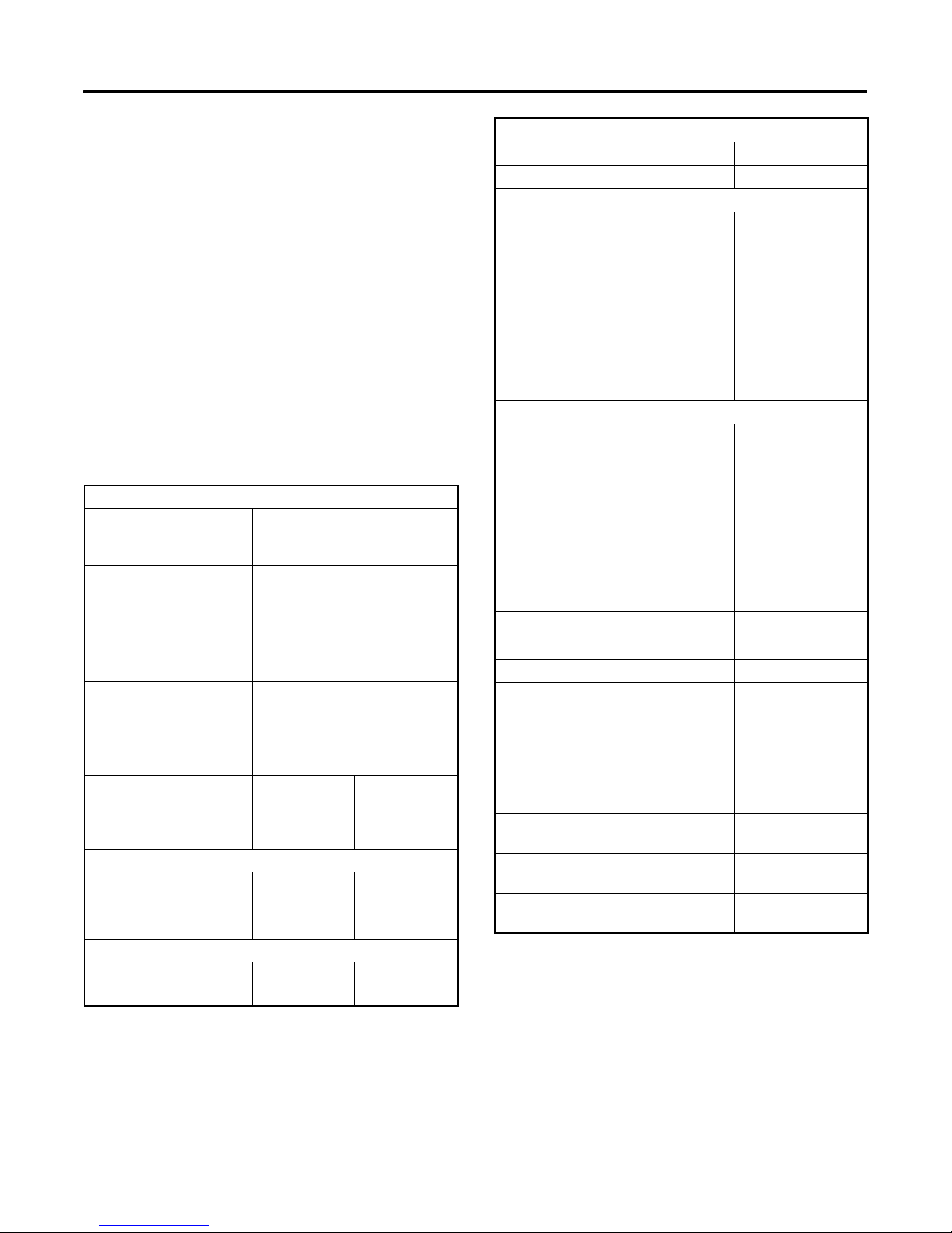
Engine
Specification
Engine Prealarm and
Shutdown Switches
Anticipatory high engine
temperature switch
Anticipatory low oil
pressure switch
High engine temperature
shutdown switch
Low oil pressure
shutdown switch
High exhaust
temperature switch (wet
exhaust only)
Controller Gauge
Senders
Oil Pressure Sender
0kPa(0psi) 120 (+9/--8) 240 (+17/--15)
172 kPa (25 psi) 76.5 (+6/--7.5) 153 (+12/--15)
690 kPa (100 psi) 16.8 33.5
Water Temperature Sender
54° C (130° F) 100 ±15 180 ±12
82° C (180° F) 40 ±6 71 ±8
COZ/CFOZ and EOZ/EFOZ
Models
96_ C (205_ F) ±7
138 kPa ±14 kPa
(20 psi ±2)
103_ C (218_ F) ±7
103 kPa ±14 kPa
(15 psi ±2)
88--102_ C
(190--215_ F) ±5
Specification
(in ohms)
COZ/CFOZ
Models
Specification
(in ohms)
EOZ/EFOZ
Models
Generator
Component Specification Value
Controller/battery electrical system 12 or 24 volts DC
Generator field resistance (F+/ F--):
40/50COZ and 33/40CFOZ 2.0--2.9 ohms
65COZ and 50CFOZ 1.8--2.2 ohms
40EOZ and 33EFOZ 2.1--2.5 ohms
50EOZ and 40EFOZ 2.7--3.1 ohms
65/80EOZ and 55/70EFOZ 1.7--2.1 ohms
99EOZ and 80EFOZ 2.0--2.4 ohms
125EOZ and100EFOZ 1.4--1.8 ohms
150EOZ and 125EFOZ 1.6--2.0 ohms
Exciter armature resistance:
40/50COZ and 33/40CFOZ 0.13 ohms
65COZ and 50CFOZ 0.27 ohms
40EOZ and 33EFOZ 0.23 ohms
50EOZ and 40EFOZ 0.14 ohms
65/80EOZ and 55/70EFOZ 0.27 ohms
99EOZ and 80EFOZ 0.27 ohms
125EOZ and100EFOZ 0.27 ohms
150EOZ and 125EFOZ 0.27 ohms
SCR assembly terminal nut torque 1.4 Nm (12 in. lbs.)
Fan to rotor flange torque 29 Nm (260 in. lbs.)
Drive disks to rotor shaft torque 61 Nm (45 ft. lbs.)
Speed sensor air gap 0.36--0.71 mm
(0.014--0.028 in.)
Speed sensor voltage 2 (black) &
16 (white)
3--6 volts DC
2 (black) & 24 (red)
8--10 volts DC
Electronic governor magnetic pickup
air gap
Magnetic pickup output voltage
during cranking
Flex plate to flywheel bolt torque
(3/8-16)
0.36--0.71 mm
(0.014--0.028 in.)
2.5 volts AC min.
52.9 Nm
(39 ft. lbs.)
TP-5737 5/01 1Section 1 Specifications
Page 16
1.3 Accessories
1.3.1 Remote Annunciator Kit
Kohler Co. offers several accessories to finalize the
installation and to add convenience to operation and
service. Accessories vary with each generator set
model and controller. Kohler Co. offers accessories
factory-installed and/or shipped loose. Some
accessories are available only with microprocessor
controllers. Obtain current information by contacting
your local authorized service distributor/dealer.
Several accessories available at the time of print of this
publication are detailed in the following subsections.
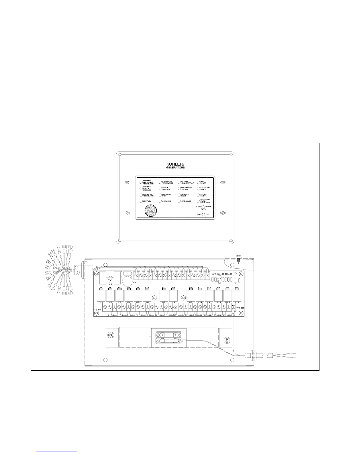
Remote Annunciator
A remote annunciator allows convenient monitoring of
the generator set’s condition from a remote location.
See Figure 1-1. The flush-mounted annunciator panel
extends all of the fault and prealarm lights/audio of the
Decision-Maker 3+ controller. The remote annunciator
includes an alarm horn, an alarm silence switch, a lamp
test, and the same lamp indicators (except air damper
and auxiliary prealarm) as the microprocessor
controller, plus the following:
Line Power. Lamp illuminates to indicate the power
source is shore power.
Generator Power. Lamp illuminates to indicate the
power source is the generator set.
14-Relay Dry Contact Box
42A 2 K1 K2 K3 K4 K5 K6 K7 K8 K9 K10 K11 K13 K14K12
CONTACTRATINGS: 10A@120VAC RES.LOAD
INPUT
NO C CNO CNO CNO CNO CNO CNO CNO CNO CNO CNO CNO CNO CNO
K1 K2 K3 K4 K5 K6 K7 K8 K9 K10 K11 K12 K13 K14
.01A@28VDC MIN.
10A@28VDC MAX.
42B
FBA--1
10 AMP
LOT NO.
P
Figure 1-1 Remote Annunciator with 14-Relay Dry Contact Kit
PCBASSY A--320639
N
P
A-344522TP-5750-1
TP-5737 5/012 Section 1 Specifications
Page 17
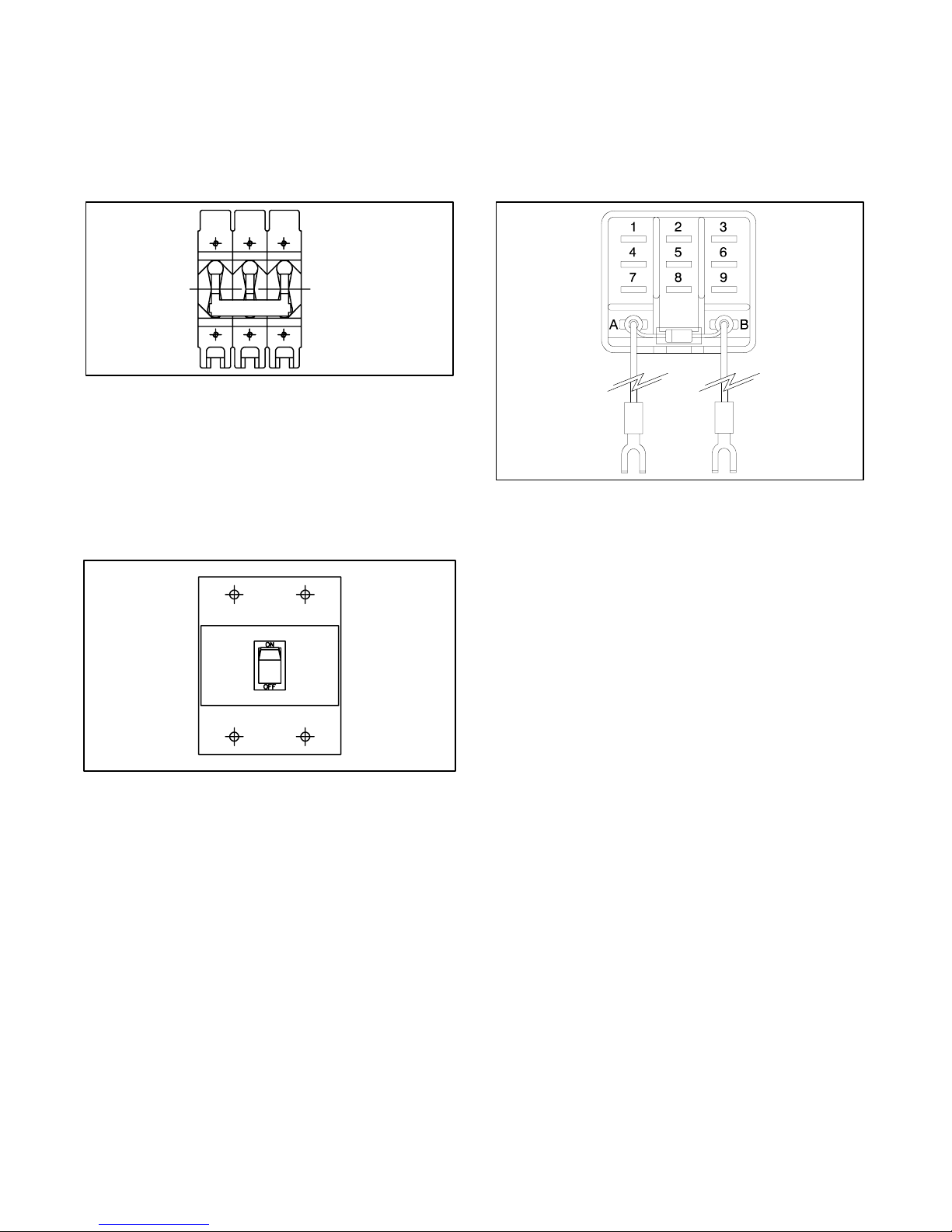
1.3.2 Safeguard Breaker
1.3.4 Run Relay Kit
The safeguard breaker senses output current on each
generator phase and shuts off the AC voltage regulator
in the event of a sustained overload or short circuit. It is
not a line circuit breaker and does NOT disconnect the
generator from the load. See Figure 1-2.
X-796
Figure 1-2 Safeguard Breaker
1.3.3 Line Circuit Breaker
The line circuit breaker interrupts generator output in the
event of an overload or short circuit. Use the kit to
manually disconnect the generator set from the load
when servicing the generator set. See Figure 1-3.
The run relay kit energizes only when the generator set
is running. Typically, the three sets of contacts control
air intake and/or compartment ventilation fans.
However, alarms and other signalling devices can also
connect to the contacts. See Figure 1-4.
273705
Figure 1-4 Run Relay Kit
TP-5352-1
Figure 1-3 Line Circuit Breaker
TP-5737 5/01 3Section 1 Specifications
Page 18
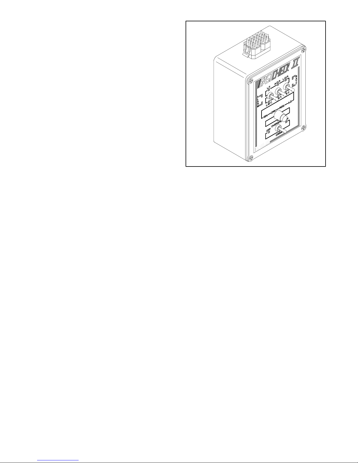
1.3.5 FASTCHECK Diagnostic Tester
(Microprocessor Controller Only)
The FASTCHECKâdiagnostic tester simulates engine
operation to identify faults in the controller and engine
circuitry. Use the FASTCHECK
startup problems or to test and troubleshoot the
controller when the controller is removed from the
generator. Perform tests without starting the generator
set. Functions performed by the FASTCHECKâare
listed below; refer to Figure 1-5 to identify LEDs and
switches.
â
when troubleshooting
LEDs on the FASTCHECK
â
indicate the energizing of
the following circuits:
D Fuel solenoid (diesel)
D Engine crank
D AC voltage regulator
D Battery connection (correct polarity)
D Engine malfunction alarm and/or alarm shutdown
â
Switches on the FASTCHECK
D Engine cranking
D Engine running
D Engine overspeed
D Low fuel
D Low engine coolant temperature
D Anticipatory low engine oil pressure
D Anticipatory high engine coolant temperature
D Low engine oil pressure
D High engine coolant temperature
simulate the following:
B-291930
Figure 1-5 FASTCHECKâDiagnostic Tester
TP-5737 5/014 Section 1 Specifications
Page 19

2.1 Fast-Responset II Concepts
The generator excitation system uses a permanent
magnet exciter with a silicon controlled rectifier (SCR)
assembly that controls the amount of DC current fed to
the generator field. This type of system uses a voltage
regulator that signals the SCR assembly through an
optocoupler. The voltage regulator monitors generator
output voltage and engine speed and signals the SCR
assembly to turn on or off accordingly through the
optocoupler. The optical coupler consists of a light
emitting diode (LED) mounted on the stationary end
bracket and a photo transistor mounted on the rotating
shaft. The photo transistor picks up the infrared signal
from the LED and signals the SCR assembly to turn on
or off, depending upon the need, as dictated by the
voltage regulator. See Figure 2-1.
Section 2 Operation
2
3
1
4
7
5
6
8
The voltage recovery period of this type of generator is
several times faster than the conventionally wound field
brushless generator because the generator set does not
have to contend with the inductance of the exciter field.
The generator set also has better recovery
characteristics than the static-excited machine because
it is not dependent upon the generator set output voltage
for excitation power. Possibly the greatest advantage of
this type of machine is its inherent ability to support
short-circuit current and allow system coordination for
tripping downstream branch circuit breakers.
The generator set systems deliver exciter current to the
main field within 50 milliseconds (0.050 seconds) of a
change in load demand.
2.2 Short Circuit Performance
When a short circuit occurs in the load circuit(s) being
served, output voltage drops and amperage
momentarily rises to 600--1000% of the generator set’s
rated current until removal of the short. The SCR
assembly sends full exciter power to the main field. The
generator then sustains up to 300% of its rated current.
Sustained high current causes correspondingly rated
load circuit fuses/breakers to trip. The safeguard
breaker kit shuts down the excitation system in the event
of a sustained heavy overload or short circuit.
12
11
13
16
1. Main armature
2. Main field
3. Main generator
4. Stator
5. SCR assembly
6. Exciter armature
7. Rotor
8. Exciter generator
9. Exciter field magnets
10. Optical coupler
11. LED board (PCB assembly)
12. Photo transistor board (PCB assembly)
13. AC voltage regulator
14. Starting battery
15. Safeguard breaker (optional)
16. Main output leads
15
Figure 2-1 Alternator Schematic
9
10
14
TP-5353-1
TP-5737 5/01 5Section 2 Operation
Page 20

2.3 Prestart Checklist
To ensure continued satisfactory operation perform the
following checks or inspections before or at each
startup, as designated, and at the intervals specified in
the service schedule. In addition, some checks require
verification after the unit starts.
Air Cleaner. Check for a clean and installed air cleaner
element to prevent unfiltered air from entering the
engine.
Air Inlets. Check for clean and unobstructed air inlets.
Air Shrouding. Check for securely installed and
positioned air shrouding.
Battery. Check for tight battery connections. Consult
the battery manufacturer’s instructions regarding
battery care and maintenance.
Fuel Level. Check the fuel level and keep the tank(s)
full to ensure adequate fuel supply.
Oil Level. Maintain the oil level at or near, not over, the
full mark on the dipstick.
Operating Area. Check for obstructions that could
block the flow of cooling air. Keep the air intake area
clean. Do not leave rags, tools, or debris on or near the
generator set.
Seawater Pump Priming. Prime the seawater pump
before initial startup. To prime the pump: (1) close the
seacock, (2) remove the hose from the water-filter
outlet, (3) fill the hose and seawater pump with clean
water, (4) reconnect the hose to the water filter outlet,
and (5) open the seacock. Confirm sea water pump
operation on startup as indicated by water discharge
from the exhaust outlet.
Coolant Level. Check the coolant level according to
the cooling system maintenance information.
Drive Belts. Check the belt condition and tension of the
water pump and battery charging alternator belt(s).
Exhaust System. Check for exhaust leaks and
blockages. Check the silencer and piping condition and
check for tight exhaust system connections.
Inspect the exhaust system components (exhaust
manifold, mixing elbow, exhaust line, hose c lamps,
silencer, and exhaust outlet) for cracks, leaks, and
corrosion.
D Check the hoses for softness, cracks, leaks, or dents.
Replace the hoses as needed.
D Check for corroded or broken metal parts and replace
them as needed.
D Check for loose, corroded, or missing clamps.
Tighten or replace the hose clamps as needed.
D Check that the exhaust outlet is unobstructed.
D Visually inspect for exhaust leaks (blowby). Check
for carbon or soot residue on exhaust components.
Carbon and soot residue indicates an exhaust leak.
Seal leaks as needed.
D Ensure that the carbon monoxide detector is (1) in the
craft, (2) functional, and (3) energized whenever the
generator set operates.
2.4 Marine Inspection
Kohler Co. recommends that all boat owners have their
vessels—especially the exhaust system attached to the
generator set—inspected at the start of each boating
season by the local Coast Guard Auxiliary. If there is no
Coast Guard Auxiliary in the area, contact an authorized
Kohler distributor/dealer for the inspection.
m:op:001:003
2.5 Angular Operation
See Figure 2-2 for angular operation limits for units
covered in this manual.
Intermittent—
Continuous
25_ 30_
Maximum value for all directions
3 minutes or less
Figure 2-2 Angular Operation
m:op:001:004
2.6 Exercising the Generator Set
Operate the generator set under load once each week
for one hour with an operator present.
The operator should perform all of the prestart checks
before starting the exercise procedure. Start the
generator set according to the starting procedure in the
controller section of this manual. While the generator
set is operating, listen for a smooth-running engine and
visually inspect the generator set for fluid or exhaust
leaks.
x:op:001:005
TP-5737 5/016 Section 2 Operation
Page 21
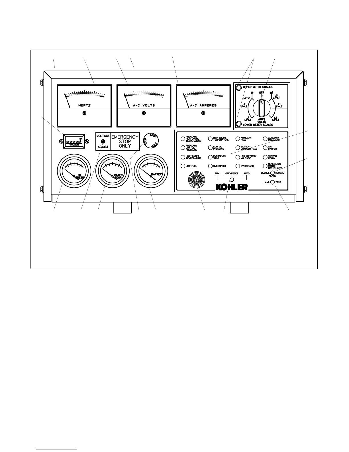
2.7 Decision-Makerä 3+ 16-Light Microprocessor Controller Operation
Figure 2-3 identifies the Decision-Makert 3+ 16-light controller’s indicators and controls and their functions.
12 34 5 6
18
1. Fuses (inside controller)
2. Frequency meter
3. AC voltmeter
4. Controller TB1 and TB2 terminal strips (on circuit board)
5. AC ammeter
6. Scale lamps (upper/lower)
7. Selector switch
8. Annunciator panel lamps
9. Alarm silence switch
10. Lamp test
11. Generator set master switch
12. Alarm horn
13. DC voltmeter
14. Emergency stop switch, if equipped
15. Water temperature gauge
16. Voltage adjustment
17. Oil pressure gauge
18. Hourmeter
7
8
9
1011121314151617
ADV-5849 P1
Figure 2-3 Decision-Makert 3+, 16-Light Microprocessor Controller
TP-5737 5/01 7Section 2 Operation
Page 22
2.7.1 Controls and Indicators
The following table describes the controls and indicators
located on the controller.
Name Description
AC ammeter The meter displays the AC output
AC voltmeter The meter displays the AC output
DC voltmeter The meter displays the voltage of
Alarm horn The horn sounds if any fault or
Alarm silence switch The switch disconnects the alarm
Auxiliary fault lamp The lamp flashes or lights when
Frequency meter The meter displays the frequency
Generator set master
switch
High engine
temperature lamp
Hourmeter The hourmeter records the
amperage. Use the selector
switch to choose the phase
current.
voltage. Use the selector switch to
choose the output lead circuits.
the starting battery(ies).
anticipatory condition exists.
Place the generator set master
switch in the AUTO position before
silencing the horn. See the
Controller Resetting Procedure
later in this section.
during service (place the generator
set master switch in the AUTO
position before silencing the alarm
horn). Restore the alarm horn
switches at all locations (controller,
remote annunciator, and
audio/visual alarm) to normal
positions after correcting the fault
shutdown to avoid reactivating the
alarm horn. See the Controller
Resetting Procedure later in this
section.
the controller detects a fault. See
the lamp conditions section
following.
(Hz) of the generator set output
voltage.
The switch functions as the
controller reset and generator set
operation switch.
The lamp illuminates if the
generator set shuts down because
of high engine temperature.
Shutdown occurs 5 seconds after
the engine reaches temperature
shutdown range.
generator set total operating hours
for reference in maintenance
scheduling.
Lamp test switch The switch tests the controller
Low oil pressure
lamp
Overcrank lamp The lamp illuminates and cranking
Overspeed lamp The lamp illuminates if the
Water temperature
gauge
Oil pressure gauge The gauge displays the engine oil
Scale lamps
(upper/lower)
Selector switch The switch selects the generator
Voltage adjustment
potentiometer
indicator lamps.
The lamp illuminates if the
generator set shuts down because
of low oil pressure. Shutdown
occurs 5 seconds after the engine
reaches oil pressure shutdown
range.
stops if the engine does not start
after 45 seconds of continuous
cranking or 75 seconds of cyclic
cranking.
The cranking stops and overcrank
lamp lights after 15 seconds if the
starter or engine does not turn
(locked rotor).
The overcrank lamp flashes if the
speed sensor signal is absent
longer than one second.
NOTE: The generator set
controller’s automatic restart
function attempts to restart the
generator set if the engine speed
drops below 13 Hz (390 rpm).
Continued decreased engine
speed causes an overcrank
condition.
generator set shuts down because
governed frequency on 50 and
60 Hz models exceeds 70 Hz.
The gauge displays the engine
coolant temperature.
pressure.
The lamps indicate which AC
voltmeter and/or ammeter scales
to read.
set output circuits to measure.
When switched to a position with
two circuit labels, measure
amperage on the lead shown in
the upper label and measure
voltage between the two leads
shown in the lower label. The AC
ammeter and voltmeter function
only with the switch in the ON
position.
The potentiometer fine-tunes
(±5%) the generator set output
voltage.
TP-5737 5/018 Section 2 Operation
Page 23

Name Description
Auxiliary prealarm
lamp
The lamp illuminates when
customer-provided sensing
devices activate the pump.
Emergency stop
lamp
The lamp illuminates and the
generator set shuts down when
energizing the optional emergency
stop switch. The lamp needs the
optional emergency stop switch to
function.
Generator switch not
in auto lamp
The lamp illuminates when the
generator set master switch is in
the RUN or OFF/RESET position.
Low fuel lamp The lamp illuminates when the fuel
level in the tank approaches
empty. The lamp needs a low fuel
sensor in the fuel tank to function.
High water
temperature lamp
The lamp illuminates when the
water temperature approaches
shutdown range. The lamp needs
an optional prealarm sender kit to
function.
Prealarm high engine
temperature lamp
The lamp illuminates when the
engine coolant temperature
approaches shutdown range. The
lamp needs an optional prealarm
sender kit to function.
Prealarm low oil
pressure lamp
The lamp illuminates when the
engine oil pressure approaches
shutdown range. The lamp needs
an optional prealarm sender kit to
function.
System ready lamp The lamp illuminates when the
generator set master switch is in
AUTO position and the system
senses no faults.
Emergency stop
switch
The switch, if activated, instantly
shuts down the generator set in
emergency situations. Use the
emergency stop switch for
emergency shutdowns only. Use
the generator set master switch for
normal shutdowns.
2.7.2 Fuses and Terminal Strips
The following table describes the controller circuit board
fuses and controller terminal strips.
Name Description
3-amp remote
annunciator fuse
3-amp controller fuse The fuse protects the controller
15-amp engine and
accessories fuse
Controller TB1
terminal strip
Controller TB2
terminal strip
The fuse protects the remote
annunciator circuit, A/V alarm, and
isolated alarm kit, if equipped.
circuit board, speed sensor, and
lamp circuit board.
Thefuseprotectsthe
engine/starting circuitry and
accessories.
The terminal strip provides
connection points for
customer-supplied sensing
devices and generator set
accessories such as the
emergency stop switch, remote
start stop/switch, audio/visual
alarms, etc., to the controller.
Figure 2-4 shows the location of
the TB1 terminal strip on the
controller circuit board. Refer to
the wiring diagrams for information
on connecting accessories to the
TB1 terminal strip.
The terminal strip provides
connection points for crank mode
selection (cyclic or continuous)
and remote start/stop switch inputs
of operation. Figure 2-4 shows the
location of the TB2 terminal strip
on the controller circuit board.
Refer to the wiring diagrams for
connection information.
12
TP-5737 5/01 9Section 2 Operation
3
R41
LED4
P2
1. TB1 terminal strip
2. TB2 terminal strip
3. Fuses
P1
Figure 2-4 TB1 and TB2 Terminal Strips on
Decision-Makert 3+ Controller Circuit
Board
A-336415-A
Page 24

2.7.3 Auxiliary Fault Lamp Conditions
2.7.4 Starting the Generator Set
The following descriptions define the possible auxiliary
fault lamp conditions.
Flashing Lamp Conditions
No AC Output. The auxiliary lamp flashes immediately
if the controller senses no AC output while the generator
set runs (except during the first 10 seconds after
startup). The flashing stops and the light goes out when
the controller senses AC output. The controller requires
no manual reset.
Low Battery Voltage. The auxiliary lamp flashes if the
battery power was reconnected or was low and then
restored while the generator set master switch was in
the RUN or AUTO position. A possible cause is a
temporary low battery condition when the battery is
weak or undersized for the application. To clear the low
battery voltage condition, place the generator set
master switch in the OFF/RESET position.
Continuous-On Lamp Conditions
Emergency Stop Switch Energized. Upon activation
of the emergency stop switch, if equipped, the auxiliary
lamp lights and the generator set shuts down
immediately.
Emergency Stop Switch Reset. Resetting the
optional emergency stop switch while the generator set
master switch is in the AUTO or RUN position causes
the auxiliary lamp to light. Place the generator set
master switch in the OFF/RESET position to clear the
auxiliary lamp ON condition.
Note: Auxiliary Delay Shutdown. The auxiliary lamp
lights and the engine shuts down 5 seconds after
the high oil temperature (P1-13) or auxiliary delay
shutdown (P1-15) fault, if equipped, occurs.
Auxiliary Delay Shutdown is inhibited during the
first 30 seconds after crank disconnect.
The following procedures describe starting the
generator set.
Local Starting (Nonautomatic). Move the generator
set master switch to the RUN position to start the
generator set at the controller.
Note: The alarm horn sounds whenever the generator
set master switch is not in the AUTO position.
Automatic (Auto) Starting. Move the generator set
master switch to the AUTO position to allow startup by
the automatic transfer switch or remote start/stop switch
(connected to controller terminals TB1-3 and TB1-4).
Note: The transient start/stop function of the
Decision-Makert3+ controller prevents
accidental cranking of the rotating engine. When
the generator set master switch is momentarily
placed in the OFF/RESET position, then quickly
returned to RUN, the generator set slows to
249 rpm and then recranks before returning to
rated speed.
Note: The Decision-Makert 3+ controller’s automatic
restart function attempts to restart the generator
set if the engine speed drops below 390 rpm
(generator output frequency of 13 Hz).
Continued decreased engine speed causes an
overcrank fault condition.
Crank Mode Selection
The Decision-Makert3+ controller cranks continuously
for up to 45 seconds or cyclically for up to 75 seconds
(crank 15 seconds, rest 15 seconds, crank 15 seconds,
etc.) before overcrank shutdown. Select the crank
mode (cyclic or continuous) on the controller circuit
board terminal strip. For cyclic cranking, leave circuit
board terminal TB2-9 open. For continuous cranking,
attach a jumper between circuit board terminal TB2-9A
(ground) and terminal TB2-9.
Note: Overvoltage Shutdown. If a generator set is
equipped with this kit, the auxiliary lamp lights
and the engine shuts down immediately when an
overvoltage condition occurs.
Note: Auxiliary Immediate Shutdown. The auxiliary
lamp lights and the engine shuts down
immediately when any customer-supplied
sensing devices connected to auxiliary
immediate shutdown ports (P1-17 and P1-18)
activate them.
x:op:005:004
2.7.5 Stopping the Generator Set
The following procedures describe stopping the
generator set.
Normal Stopping
1. Cooldown. Run the generator set at no load for
5 minutes to ensure adequate engine cooldown.
2. Stopping. Move the generator set master switch
to the OFF/RESET position. The engine stops.
TP-5737 5/0110 Section 2 Operation
Page 25

Note: The generator set continues running during
a 5-minute cooldown cycle if a remote
switch or automatic transfer switch signals
the engine to stop.
Emergency Stopping
Move the generator set master switch to the
OFF/RESET position or activate the remote emergency
stop, if equipped, for immediate shutdown. The
controller AUXILIARY lamp lights and the generator set
shuts down on activation of the emergency stop switch.
The remote annunciator and/or A/V alarms, if equipped,
signal an emergency stop.
2.7.6 Prime Power Mode Operation
The Decision-Makert 3+ controller operates in either
the normal mode or the prime power mode. In prime
power mode, the controller draws less current,
minimizing the battery drain. Consider using the prime
power mode for installations that do not have a battery
charger.
Moving the generator set master switch to the
OFF/RESET position disables all controller functions.
Moving the generator set master switch to the AUTO
position restores controller functions.
Enabling and Disabling the Prime Power Mode.
Enable the prime power mode by connecting jumpers
across the following terminals on terminal strip TB2 on
the controller circuit board:
D TB2-1P and TB2-2P
D TB2-3P and TB2-4P
D TB2-3 and TB2-4
See Figure 2-4. Remove the jumpers listed above to
disable the prime power mode.
Prime Power Starting. The prime power mode
provides local starting only at the controller. When the
generator set master switch is in the OFF/RESET
position, the controller functions are inoperative. Move
the generator set master switch to the AUTO position to
start the generator set. Do not start the generator set
with the master switch in the RUN position because the
alarm horn sounds.
Note: Move the generator set master switch to the
AUTO position to return controller functions to
normal.
2.7.7 Fault Shutdowns
The generator set shuts down automatically under the
following fault conditions and cannot be restarted until
the fault condition is corrected. The system
automatically resets when the problem is corrected or
the generator set cools (if high engine temperature was
the fault).
Name Description
High engine
temperature
High exhaust
temperature
Low coolant level
(water-cooled
engines only)
Low oil pressure Shutdown occurs 5 seconds after
Overcrank Shutdown occurs after 45 seconds
Overspeed Shutdown occurs immediately
Overvoltage
(optional)
Shutdown occurs 5 seconds after
the fault. The high engine
temperature shutdown does not
function during the first 5 seconds
after startup.
NOTE: The high temperature
shutdown functions only when the
coolant level is in the operating
range.
Shutdown occurs 5 seconds after
the fault. The high exhaust
temperature shutdown does not
function during the first 5 seconds
after startup.
Shutdown occurs 5 seconds after
fault. The low coolant level
shutdown does not function during
the first 5 seconds after startup.
the fault. The low oil pressure
shutdown does not function during
the first 5 seconds after startup.
NOTE: The low oil pressure
shutdown does not protect against
low oil level. Check the engine oil
level.
of continuous cranking or 75
seconds of cyclic cranking (crank
15 seconds, rest 15 seconds,
crank 15 seconds, etc.).
when governed frequency on 50
and 60 Hz models exceeds 70 Hz.
The generator set shuts down and
the auxiliary lamp lights when
voltage is 15% or more over the
nominal voltage for 2 seconds or
longer.
NOTE: Overvoltage can damage
sensitive equipment in less than
one second. Install separate
overvoltage protection on on-line
equipment requiring faster
shutdown.
x:op:005:007
Prime Power Stopping. Move the generator set
master switch to the OFF/RESET position to stop the
generator set and power down the controller.
TP-5737 5/01 11Section 2 Operation
Page 26

2.7.8 Controller Resetting Procedure
(Following Fault Shutdown)
2.7.9 Resetting the Emergency Stop
Switch
Use the following procedure to restart the generator set
after a fault shutdown. Refer to Resetting the
Emergency Stop Switch in this section to reset the
generator set after an emergency stop.
1. Place the controller alarm horn silence switch in the
SILENCE position. Place the A/V annunciator
alarm switch, if equipped, in the SILENCE position
to stop the alarm horn. The A/V annunciator lamp
stays lit. (The A/V alarm uses one lamp to indicate
a fault shutdown; the respective fault lamp on the
remote annunciator lights to indicate a fault
condition.)
2. Disconnect the generator set from the load using
the line circuit breaker or automatic transfer switch.
3. Correct the cause of the fault shutdown. See the
Safety Precautions at the beginning of this section
before proceeding.
4. Place the generator set master switch in the
OFF/RESET position and then in the RUN position
to start the generator set. The A/V annunciator
alarm horn sounds and the lamp, if equipped,
darkens.
Use the following procedure to restart the generator set
after an emergency stop switch shutdown. Refer to the
Controller Resetting Procedure in this section to restart
the generator set following a fault shutdown. The
generator set does not crank until the operator
completes the resetting procedure.
Note: The controller auxiliary lamp lights when the
generator set master switch is in the RUN or
AUTO position during the resetting procedure.
Procedure to Restart the Generator Set After an
Emergency Stop Shutdown:
1. Determine the cause of the emergency stop and
correct the problem(s).
2. Reset the controller emergency stop switch by
rotating the switch clockwise until the switch
springs back to the original position. See
Figure 2-3.
3. Toggle the generator set master switch to
OFF/RESET and then to RUN or AUTO to restart
the generator set.
5. Test operate the generator set to verify that the
cause of the shutdown has been corrected.
6. Reconnect the generator set to the load via the line
circuit breaker or automatic transfer switch.
7. Place the generator set master switch in the AUTO
position for startup by a remote transfer switch or
remote start/stop switch. Place the A/V
annunciator alarm switch, if equipped, in the
NORMAL position.
8. Place the generator set master switch in the AUTO
position before silencing the alarm horn.
TP-5737 5/0112 Section 2 Operation
Page 27

2.8 Expanded Decision-Makert 1 Controller Operation
For identification of the expanded controller’s indicators and controls and their functions, refer to Figure 2-5.
13
1. Frequency meter
2. AC voltmeter
3. AC ammeter
4. Scale lamps (upper/lower)
5. Selector switch
6. Hourmeter
7. Generator set master switch
1
12
2
11
Figure 2-5 Expanded Decision-Makert 1 Controller
3
10
9
8. Voltage adjustment potentiometer
9. Fault lamp
10. 10-amp controller fuse
11. DC voltmeter
12. Water temperature gauge
13. Oil pressure gauge
4
8
7
5
6
ADV-5849E-B
x:op:002:001
2.8.1 Controls and Indicators
The following table describes the controls and indicators
located on the controller.
Name Description
AC voltmeter The meter displays the AC output
AC ammeter The meter displays the AC output
DC voltmeter The meter displays the voltage of the
Fault lamp The lamp illuminates during engine
Frequency meter The meter displays the frequency (Hz)
Generator set
master switch
Hourmeter The hourmeter records the generator
voltage. Use the selector switch to
choose the output lead circuits.
amperage. Use the selector switch to
choose the phase currents.
starting battery(ies).
shutdown if the engine shuts down
because of one of the following faults:
high engine temperature, low water
level, low oil pressure, overcrank, or
overspeed. See Section 2.8.4, Fault
Shutdowns, for additional shutdown
information.
of the generator set output.
The switch functions as the controller
reset and generator set operation
switch.
set total operating hours for reference
in maintenance scheduling.
Oil pressure
gauge
Scale lamps
(upper/lower)
The gauge displays the engine oil
pressure.
The lamps indicate which AC
voltmeter and/or ammeter scales to
read.
Selector switch The switch selects the generator set
output circuits to measure. When
switched to a position with two circuit
labels, measure amperage on the
lead shown in the upper label and
measure voltage between the two
leads shown in the lower label. The
AC ammeter and voltmeter function
only with the switch in the ON
position.
Voltage
adjustment
The potentiometer fine-tunes (±5%)
the generator set output voltage.
potentiometer
Water
temperature
The gauge displays the engine
coolant temperature.
gauge
10-amp controller
fuse
The fuse protects the controller
circuitry from short circuits and
overloads.
TP-5737 5/01 13Section 2 Operation
Page 28

2.8.2 Starting the Generator Set
The following procedure describes the actions required
to start the generator set.
Local Starting. Move the generator set to the RUN
position to immediately start the generator set.
Auto (Automatic) Starting. Move the generator set
master switch to the AUTO position to allow startup by
the automatic transfer switch or the remote start/stop
switch (connected to controller terminals TB1-3 and
TB1-4).
Note: The controller provides up to 30 seconds of
continuous cranking before overcrank shutdown
occurs.
x:op:002:003
2.8.3 Stopping the Generator Set
2.8.5 Controller Resetting Procedure
(Following Fault Shutdown)
Use the following procedure to restart the generator set
after a fault shutdown.
1. Disconnect the generator set from the load using
the line circuit breaker or automatic transfer switch.
See the Safety Precautions at the beginning of this
section before proceeding.
2. Correct the cause of the fault shutdown. See the
Safety Precautions at the beginning of this section
before proceeding.
3. Start the generator set by moving the generator set
master switch to RESET/OFF and then to RUN.
4. Verify that the cause of the shutdown has been
corrected by test operating the generator set.
The following procedure describe how to stop the
generator set.
Normal Stopping
1. Cooldown. Run the generator set at no load for
5 minutes to ensure adequate engine cooldown.
2. Stopping. Move the generator set master switch
to the OFF/RESET position. The engine stops.
x:op:002:004
2.8.4 Fault Shutdowns
The generator set shuts down automatically under the
following fault conditions and cannot be restarted until
the fault condition is corrected. The system automatically
resets when the problem is corrected or the generator
set cools (if high engine temperature was the fault).
The fault lamp does not stay lit after the generator set
shuts down on a fault condition.
5. Reconnect the generator set to the load using the
line circuit breaker or automatic transfer switch.
6. Move the generator set master switch to the AUTO
position for startup by remote transfer switch or
remote start/stop switch.
Fault Description
High engine
temperature
High exhaust
temperature
Low coolant level Shutdown occurs 5 seconds after the
Low oil pressure Shutdown occurs 5 seconds after the
Overcrank Shutdown occurs after 30 seconds of
Overspeed Shutdown occurs immediately when
Shutdown occurs 5 seconds after the
fault. The high engine temperature
shutdown does not function during the
first 5 seconds after startup.
Note: The high temperature
shutdown functions only when the
coolant level is in the operating range.
Shutdown occurs 5 seconds after the
fault. The high exhaust temperature
shutdown does not function during the
first 5 seconds after startup.
fault. The low coolant level shutdown
does not function during the first
5 seconds after startup.
fault. The low oil pressure shutdown
does not function during the first
5 seconds after startup.
Note: The low oil pressure shutdown
does not protect against low oil level.
Check the oil level at the engine.
continuous cranking. Shutdown
occurs after 30 seconds if the engine
or starter does not turn (locked rotor).
the governed frequency on the 50 and
60 Hz models exceeds 70 Hz.
x:op:002:006
TP-5737 5/0114 Section 2 Operation
Page 29

2.9 Standard Decision-Makert 1
Controller Operation
For identification of the standard basic controller’s
indicators and controls and their functions, refer to
Figure 2-6.
1
2.9.2 Starting the Generator Set
The following procedures describe the actions required
to start the generator set.
Local Starting. Move the generator set master switch
to the RUN position to immediately start the generator
set.
Automatic (Auto) Starting. Move the generator set
master switch to the AUTO position to allow startup by
the automatic transfer switch or the remote start/stop
switch (connected to controller terminals TB1-3 and
TB1-4).
Note: The controller provides up to 30 seconds of
continuous cranking before the overcrank
shutdown occurs.
x:op:004:003
345
1. Hourmeter
2. Voltage adjustment
3. 10-amp controller fuse
4. Fault lamp
5. Generator set master switch
2
A-227600
Figure 2-6 Decision-Makert 1 Controller
x:op:004:001
2.9.1 Controls and Indicators
The following table describes the controls and indicators
located on the controller.
Name Description
Fault lamp Lamp illuminates during engine
Generator set master
switch
Hourmeter Hourmeter records the generator
Voltage adjust
potentiometer
10-amp controller
fuse
shutdown if the engine shuts down
because of one of the following
faults: high engine temperature,
low water level, low oil pressure,
overcrank, or overspeed. See
Section 2.9.4, Fault Shutdowns,
for additional shutdown
information.
Switch functions as the controller
reset and generator operation
switch.
set total operating hours for
reference in maintenance
scheduling.
Potentiometer fine-tunes (±5%)
generator output voltage.
Fuse protects the controller
circuitry from short circuits and
overloads.
x:op:004:002
2.9.3 Stopping the Generator Set
The following procedure describe how to stop the
generator set.
Normal Stopping
1. Cooldown. Run the generator set at no load for
5 minutes to ensure adequate engine cooldown.
2. Stopping. Move the generator set master switch
to the OFF/RESET position. The engine stops.
x:op:004:004
TP-5737 5/01 15Section 2 Operation
Page 30

2.9.4 Fault Shutdowns
The generator set shuts down automatically under the
following fault conditions and cannot be restarted until
the fault condition is corrected. The system automatically
resets when the problem is corrected or the generator
set cools (if high engine temperature was the fault).
Fault Description
High engine
temperature
High exhaust
temperature
Low coolant level Shutdown occurs 5 seconds after
Low oil pressure Shutdown occurs 5 seconds after
Overcrank Shutdown occurs after 30 seconds
Overspeed Shutdown occurs immediately
Shutdown occurs 5 seconds after
the fault. The high engine
temperature shutdown does not
function during the first 5 seconds
after startup.
NOTE: The high temperature
shutdown functions only when the
coolant level is in the operating
range.
Shutdown occurs 5 seconds after
the fault. The high exhaust
temperature shutdown does not
function during the first 5 seconds
after startup.
the fault. Low coolant level
shutdown does not function during
the first 5 seconds after startup.
the fault. Low oil pressure
shutdown does not function during
the first 5 seconds after startup.
NOTE: The low oil pressure
shutdown does not protect against
low oil level. Check the oil level at
the engine.
of continuous cranking. Shutdown
occurs after 30 seconds if the
engine or starter does not turn
(locked rotor).
when the governed frequency on
50 and 60 Hz models exceeds
70 Hz.
x:op:004:005
2.9.5 Controller Resetting Procedure
(Following Fault Shutdown)
Use the following procedure to restart the generator set
after a fault shutdown.
1. Disconnect the generator set from the load using
the line circuit breaker or automatic transfer switch.
See the Safety Precautions at the beginning of this
section before proceeding.
2. Correct the cause of the fault shutdown. See the
Safety Precautions at the beginning of this section
before proceeding.
3. Start the generator set by moving the generator set
master switch to RESET/OFF and then to RUN.
4. Verify that the cause of the shutdown has been
corrected by test operating the generator set.
5. Reconnect the generator set to the load using the
line circuit breaker or automatic transfer switch.
6. Move the generator set master switch to the AUTO
position for startup by remote transfer switch or
remote start/stop switch.
x:op:004:006
TP-5737 5/0116 Section 2 Operation
Page 31

Section 3 Scheduled Maintenance
3.1 General Maintenance
WARNING
Accidental starting.
Can cause severe injury or death.
Disconnect the battery cables before
working on the generator set.
Remove the negative (--) lead first
when disconnecting the battery.
Reconnect the negative (--) lead last
when reconnecting the battery.
Disabling the generator set. Accidental starting can
cause severe injury or death. Before working on the
generator set or connected equipment, disable the generator
set as follows: (1) Move the generator set master switch to the
OFF position. (2) Disconnect the power to the battery charger.
(3) Remove the battery cables, negative (--) lead first.
Reconnect the negative (--) lead last when reconnecting the
battery. Follow these precautions to prevent starting of the
generator set by an automatic transfer switch, remote
start/stop switch, or engine start command from a remote
computer.
WARNING
WARNING
Rotating parts.
Can cause severe injury or death.
Operate the generator set only when
all guards, screens, and covers are in
place.
Servicing the generator set when it is operating. Exposed
moving parts can cause severe injury or death. Keep
hands, feet, hair, clothing, and test leads away from the belts
and pulleys when the generator set is running. Replace
guards, screens, and covers before operating the generator
set.
See the Safety Precautions and Instructions at the
beginning of this manual before attempting to service,
repair, or operate the generator set. Have an authorized
distributor/dealer perform generator set service.
Engine Service. Perform generator set engine service
at the intervals specified by the engine operation
manual.
Generator Set Service. Perform generator set service
at the intervals specified by the generator set operation
manual.
If the generator set operates under dusty or dirty
conditions, use dry compressed air to blow dust out of
Hot engine and exhaust system.
Can cause severe injury or death.
the alternator. With the generator set running, direct the
stream of air in through the cooling slots at the alternator
end.
Do not work on the generator set until
it cools.
Service Log. Use the Operating Hour Service Log
located in the back of this manual to document
Servicing the exhaust system. Hot parts can cause
severe injury or death. Do not touch hot engine parts. The
engine and exhaust system components become extremely
hot during operation.
performed services.
Service Schedule. Perform maintenance on each item
in the service schedule at the designated intervals for
the life of the generator set. For example, an item
requiring service every 100 hours or 3 months also
requires service after 200 hours or 6 months, 300 hours
or 9 months, and so on.
x:sm:004:001
TP-5737 5/01 17Section 3 Scheduled Maintenance
Page 32

3.2 Generator Bearing
3.3.3 Fuel System
Replace the end bracket bearing every 10,000 hours of
operation. Service more frequently if bearing inspection
indicates excessive rotor end play or bearing damage
from corrosion or heat buildup. Replace the tolerance
ring, if equipped, if removing the end bracket. The end
bracket bearing is sealed and requires no additional
lubrication. Have all generator service performed by an
authorized service distributor/dealer.
3.3 Storage Procedure
Perform the following storage procedure before taking a
generator set out of service for three months or longer.
Follow the engine manufacturer’s recommendations, if
available, for fuel system and internal engine
component storage.
x:sm:002:001
3.3.1 Lubricating System
Prepare the engine lubricating system for storage as
follows:
1. Run the generator set for a minimum of 30 minutes
to bring it to normal operating temperature.
2. Stop the generator set.
3. With the engine still warm, drain the oil from the
crankcase.
Prepare the fuel system for storage as follows:
Diesel-Fueled Engines
1. Fill the fuel tank with #2 diesel fuel.
2. Condition the fuel system with compatible
additives to control microbial growth.
3. Change the fuel filter/separator and bleed the fuel
system. See the engine service manual.
3.3.4 Exterior
Prepare the exterior for storage as follows:
1. Clean the exterior surface of the generator set.
2. Seal all engine openings except for the air intake
with nonabsorbent adhesive tape.
3. To prevent impurities from entering the air intake
and to allow moisture to escape from the engine,
secure a cloth over the air intake.
4. Mask electrical connections.
5. Spread a light film of oil over unpainted metallic
surfaces to inhibit rust and corrosion.
x:sm:002:006a
3.3.5 Battery
4. Remove and replace the oil filter.
5. Refill the crankcase with oil suited to the climate.
6. Run the generator set for two minutes to distribute
the clean oil.
7. Stop the generator set.
8. Check the oil level and adjust, if needed.
x:sm:002:002
3.3.2 Cooling System
Prepare the cooling system for storage as follows:
1. Check the coolant freeze protection using a
coolant tester.
2. Add or replace coolant as necessary to ensure
adequate freezing protection. Use the guidelines
included in the engine operation manual.
3. Run the generator set for 30 minutes to redistribute
added coolant.
x:sm:002:003
Perform battery storage after all other storage
procedures.
1. Place the generator set master switch in the
OFF/RESET position.
2. Disconnect the battery(ies), negative (--) lead first.
3. Clean the battery. Refer to the battery
manufacturer’s instructions for the battery cleaning
procedure.
4. Place the battery in a cool, dry location.
5. Connect the battery to a float/equalize battery
charger or charge it monthly with a trickle battery
charger. Refer to the battery charger
manufacturer’s recommendations.
6. Maintain a full charge to extend battery life.
TP-5737 5/0118 Section 3 Scheduled Maintenance
Page 33

Section 4 General Troubleshooting
This section contains generator set troubleshooting,
diagnostic, and repair information.
Use the following chart as a quick troubleshooting
reference. The table groups generator set faults and
suggests likely causes and remedies. The table also
refers you to more detailed information including
sections of this manual, the generator set operation
manual (O/M), the generator set installation manual
(I/M), and the engine service manual (Engine S/M) to
correct the indicated problem.
Corrective action and testing often require knowledge of
electrical and electronic circuits. To avoid additional
problems caused by incorrect repairs, have an
authorized service distributor/dealer perform service.
NOTICE
Fuse replacement. Replace fuses with fuses of the same
ampere rating and type (for example: 3AB or 314, ceramic).
Do not substitute clear glass-type fuses for ceramic fuses.
Refer to the wiring diagram when the ampere rating is
unknown or questionable.
Maintain a record of repairs and adjustments performed
on the equipment. If the procedures in this manual do
not explain how to correct the problem, contact an
authorized distributor/dealer. Use the record to help
describe the problem and repairs or adjustments made
to the equipment.
x:gt:001:002a:
TP-5737 5/01 19Section 4 General Troubleshooting
Page 34

Section or
Reference*
Publication
Section 2
Move the controller master switch to the RUN or AUTO
position.
Section 2, W/D
Section5or6
troubleshoot the controller.[
Replace the controller master or start/stop switch. —
Troubleshoot the controller.[
Eng. O/M
cooling system.
Restore the coolant to normal operating level. Gen. O/M
Trouble Symptoms
Probable Causes Recommended Actions
abnormal noise
Excessive or
consumption
High fuel
pressure
Low oil
Overheats
Lacks power
suddenly
Stops
output voltage
No or low
Starts hard
does not start
Cranks but
crank
Does not
Controller
OFF/RESET position
x Controller master switch in the
x x x Controller fuse blown Replace the blown controller fuse. If the fuse blows again,
x x Controller circuit breaker tripped Reset the controller circuit breaker. Section 2
inoperative
x Controller fault
x Controller master or start/stop switch
x x Controller circuit board(s) inoperative Replace the controller circuit board. Section5or6
x x Air openings clogged Clean the air openings. —
Cooling System
x Impeller inoperative Replace the impeller Gen. O/M
x x Seawater strainer clogged or restricted Clean the strainer. Gen. O/M
x High temperature shutdown Allow the engine to cool down. Then troubleshoot the
equipped
x Low coolant level shutdown, if
x Coolant level low Restore the coolant to normal operating level. Gen. O/M
x Thermostat inoperative Replace the thermostat. Eng. S/M
x Cooling water pump inoperative Tighten or replace the belt. Replace the water pump. Eng. O/M or S/M
Manual; S/S—Spec Sheet; W/D—Wiring Diagram Manual
[ Have an authorized service distributor/dealer perform this service.
* Sec./Section—numbered section of this manual; ATS—Automatic Transfer Switch; Eng.—Engine; Gen.—Generator Set; I/M—Installation Manual; O/M—Operation Manual; S/M—Service
20 Section 4 Troubleshooting
TP-5737 5/01
Page 35

Section or
Section or
Reference*
Reference*
Publication
Publication
Recommended ActionsProbable Causes
Recommended ActionsProbable Causes
Eng. O/M
Verify that the battery connections are correct, clean, and
tight.
S/S
recommended battery CCA rating.
W/D
Disconnect the engine harness connector(s) then
Eng. S/M
S/S
I/M
I/M
Section 7
Eng. S/M
reconnect it to the controller.
Replace the inoperative switch. Gen. S/M or W/D
Replace the inoperative switch. Gen. S/M
Check the compression.[
sheet for wattage specifications.
exhaust system components.[
system components.[
Adjust the governor.[
Adjust the valves.[
x x Battery connections loose, corroded,
Electrical System (DC circuits)
or incorrect
x x Battery weak or dead Recharge or replace the battery. The spec sheet provides
abnormal noise
Excessive or
consumption
High fuel
pressure
Low oil
Overheats
Lacks power
suddenly
Stops
output voltage
Trouble Symptoms
TP-5737 5/01 21Section 4 Troubleshooting
No or low
Starts hard
does not start
Cranks but
crank
Does not
x x Engine harness connector(s) not
locked tight
x Fault shutdown Reset the fault switches and troubleshoot the controller. Section 2
inoperative
x High exhaust temperature switch
x x Starter/starter solenoid inoperative Replace the starter or starter solenoid. Eng. S/M
inoperative
x High water temperature switch
Engine
x x x x Air cleaner clogged Clean or replace the filter element. Gen. O/M
x x x x x Compression weak
x x x x x Engine overload Reduce the electrical load. See the generator set spec
x Exhaust system leak Inspect the exhaust system. Replace the inoperative
x Exhaust system not securely installed Inspect the exhaust system. Tighten the loose exhaust
x Vibration excessive Tighten all loose hardware. —
x x Valve clearance incorrect
x x x x Governor inoperative
Manual; S/S—Spec Sheet; W/D—Wiring Diagram Manual
[ Have an authorized service distributor/dealer perform this service.
* Sec./Section—numbered section of this manual; ATS—Automatic Transfer Switch; Eng.—Engine; Gen.—Generator Set; I/M—Installation Manual; O/M—Operation Manual; S/M—Service
Page 36

Section or
Section or
Reference*
Reference*
Publication
Publication
Recommended ActionsProbable Causes
Recommended ActionsProbable Causes
Eng. S/M
Troubleshoot the fuel solenoid.[
Eng. S/M
Clean, test, and/or replace the inoperative fuel injector.[
Eng. S/M
Adjust the fuel injection timing.[
Eng. S/M
Rebuild or replace the injection pump.[
—
bp #
Section 7
Section 7
—
Section 7
generator side of the circuit breaker.
Move the transfer switch test switch to the AUTO position. AT S O /M
Check for continuity. Section 7, W/D
Test and/or replace the rotor.[
Test and/or replace the stator.[
Tighten loose components.[
troubleshoot the voltage regulator.
Eng. O/M
Change the oil. Use oil with a viscosity suitable for the
operating climate.
abnormal noise
Excessive or
consumption
High fuel
pressure
Low oil
Overheats
Lacks power
suddenly
Stops
output voltage
Trouble Symptoms
22 Section 4 Troubleshooting
No or low
Starts hard
does not start
Cranks but
x x Fuel tank empty or fuel valve shut off Add fuel and move the fuel valve to the ON position. —
crank
Does not
Fuel System
x x x x Fuel filter restriction Clean or replace the fuel filter. Eng. O/M
x Fuel solenoid inoperative
x x x Air in fuel system (diesel only) Bleed the diesel fuel system. Eng. O/M
(diesel only)
x x x Fuel or fuel injectors dirty or faulty
(diesel only)
(diesel only)
x x x x Fuel injection timing out of adjustment
x x x Fuel feed or injection pump inoperative
x AC output circuit breaker open Reset the breaker and check for AC voltage at the
Generator
position
x Transfer switch test switch in the OFF
field open
x Wiring, terminals, or pin in the exciter
grounded)
x Main field (rotor) inoperative (open or
x Vibration excessive
x Stator inoperative (open or grounded)
x x Voltage regulator out of adjustment Adjust the voltage regulator. Section 7
x x Voltage regulator inoperative Replace the voltage regulator fuse, If the fuse blows again,
x x x Oil level low Restore the oil level. Inspect the generator set for oil leaks. Eng. O/M
Lube System
ambient temperature
x Low oil pressure shutdown Check the oil level. Eng. O/M
x x x x Crankcase oil type incorrect for
TP-5737 5/01
Manual; S/S—Spec Sheet; W/D—Wiring Diagram Manual
[ Have an authorized service distributor/dealer perform this service.
* Sec./Section—numbered section of this manual; ATS—Automatic Transfer Switch; Eng.—Engine; Gen.—Generator Set; I/M—Installation Manual; O/M—Operation Manual; S/M—Service
Page 37

Section 5 Decision-Makert 3+ Troubleshooting
5.1 Decision-Makert 3+ Controller
For external features, see Section 2, Operation.
Figure 5-1 through Figure 5-11 show the locations of
controller components and connections. Figure 5-12
1
3
contains the logic schematic showing input/output
circuits for reference in troubleshooting. This
information deals directly with the 16-light
microprocessor.
4
625
12
1. Selector switch
2. Lamp circuit board
3. Panel lamps
4. Controller DC ground terminal
5. AC fuse terminal block (TB3)
6. CT/meter scale terminal block (TB2)
Figure 5-1 Decision-Makerä 3+ Controller
TP-5737 5/01 23Section 5 Decision-Makert 3+ Troubleshooting
11 7
7. Accessory wire guide loops
8. Controller fuses
9. Lamp selection jumper
10. Control panel harness connector (P2)
11. Controller main circuit board
12. P3/P4 harness
10 9
8
A-328917-X
Page 38

15
14
16
321
4
5
6
7
13 11 91012 8
1. K2 relay: control relay (crank)
2. K3 relay: control relay (run)
3. K4 relay: emergency stop
4. LED1
5. Microprocessor chip
6. TB1 terminal strip
7. TB2 terminal strip
8. P3 connector (control panel harness) to P4 (LED indicator
panel assembly)
9. LED4 (K4 relay)
10. P1 connector (DC harness)
11. LED3 (K3 relay)
12. P2 connector (AC harness)
13. LED2 (K2 relay)
14. Fuse: 3 amp (F1) remote annunciator
15. Fuse: 3 amp (F2) controller
16. Fuse: 15 amp (F3) engine and accessories
Figure 5-2 Decision-Makerä 3+ Controller Circuit Board Components, Typical
A-336415-L
TP-5737 5/0124 Section 5 Decision-Makert 3+ Troubleshooting
Page 39

5.1.1 Decision-Maker 3+ Circuit Board
Terminal/Connector Identification
Terminal Wire Description
1 1A Emergency stop relay (K4) coil
2 1 Ground—emergency stop relay (K4)
3 42A Battery voltage (fuse #1 protected)
4 2 Ground
5 70C Generator in cool-down mode signal
6 70R Generator in running mode signal
7 56 Air damper indicator, if equipped
8 48 Emergency stop indicator
9 32A Common fault/prealarm
10 26 Auxiliary indicator
11 12 Overcrank indicator
12 39 Overspeed indicator
13 38 Low oil pressure indicator
14 36 High engine temperature indicator
15 60 System ready indicator
16 80 Not-in-auto indicator
17 41 Prealarm low oil pressure indicator
18 62 Low battery volts (active low*)
19 32 Common fault/prealarm
20 35 Low water temperature
21 40 Prealarm high engine temperature
indicator
22 63 Low fuel (active low*)
23 61 Battery charger fault (active low*)
* Check the operation of active low circuits by placing ground on
terminals so designated.
Figure 5-3 Terminal Strip TB1
Pin Description
1 Output to K1 relay (crank relay), wire 71
2 Ground for speed sensor, wire 2
3 Output to safeguard breaker terminal, wire 70 (and
K5 relay if equipped with electronic governor)
4 Not used
5 Ground (--), wire N
6 Speed sensor shield ground, wire S2
7 Output to fuel solenoid (FS), wire 70
8 Battery positive to speed sensor, wire 24
9 Input from speed sensor, wire 16
10 Not used
11 Not used
12 Input from battery positive (14P)
13 Not used
14 Input from high exhaust temperature switch,
wire 31
15 Not used
16 Input from pre-high engine temperature switch, wire
40A
17 Input from aux. immediate shutdown
18 Not used
19 Not used
20 Not used
21 Input from high engine temperature switch, wire 34
22 Input from low oil pressure switch, wire 13
23 Input from pre-low oil pressure switch, wire 41A
24 Not used
* Check the operation of active low circuits by placing ground on
terminals so designated.
Figure 5-5 P1 Connector Pins
Terminal Wire Description
1 1P Prime power operation (requires
optional kit)
2 2P Prime power operation (requires
optional kit)
3 3P Prime power operation (requires
optional kit)
4 4P Prime power operation (requires
optional kit)
5 9 Crank mode (open-cyclic ground
continuous)
6 9A Crank mode ground
7 4 Remote start (active low*)
8 3 Remote start (ground)
* Check the operation of active low circuits by placing ground on
terminals so designated.
Pin Description
1 Output to engine gauge, wire 70
2 Not used
3 Input for AC crank disconnect & instrumentation,
wire V7F
4 Not used
5 Input for AC crank disconnect & instrumentation,
wire V0
6 Engine ground, wire 2
Figure 5-6 P2 Connector Pins
Figure 5-4 Terminal Strip TB2
TP-5737 5/01 25Section 5 Decision-Makert 3+ Troubleshooting
Page 40

Pin Description
1 Ground (--), front panel, wire 2
2 Not used
3 Not used
4 Input from generator set master switch, auto
position, wire 46
5 Not used
6 Voltage (+) to front panel, wire 24
7 Output to low oil pressure indicator, wire 38
8 Output to overspeed indicator, wire 39
9 Output to overcrank indicator, wire 12
10 Output to auxiliary indicator, wire 26
11 Output to emergency stop lamp, wire 48
12 Output to pre-high engine temperature indicator,
wire 40
13 Output to high engine temperature indicator, wire 36
14 Output to system ready indicator, wire 60
15 Output to not-in-auto indicator, wire 80
16 Output to low water temperature indicator, wire 35
17 Output to pre-low oil pressure indicator, wire 41
18 Output to air damper indicator, if equipped, wire 56
19 Output to low battery volts indicator, wire 62
20 Output to battery charger fault indicator, wire 61
21 Output to low fuel indicator, wire 63
22 Output to common alarm, wire 32
23 Input from generator master switch, off/reset
position, wire 43
24 Input from generator set master switch, run position,
wire 47
Figure 5-7 P3 Connector Pins
Pin Description
1 Ground (--), front panel, wire 2
2 Not used
3 Not used
4 Output from generator set master switch, auto
position, wire 46
5 Not used
6 Voltage (+) to front panel, wire 24
7
Input to low oil pressure indicator, wire 38[
8
Input to overspeed indicator, wire 39[
9
Input to overcrank indicator, wire 12[
10 Input to auxiliary indicator, wire 26
11 Input to emergency stop lamp, wire 48
12 Input to pre-high engine temperature indicator, wire
40[
13
Input to high engine temperature indicator, wire 36[
14 Input to system ready indicator, wire 60
15 Input to not-in-auto indicator, wire 80
16
Input to low water temperature indicator, wire 35[
17
Input to pre-low oil pressure indicator, wire 41[
18 Input to air damper indicator, if equipped, wire 56
19 Input to low battery volts indicator, wire 62
20 Input to battery charger fault indicator, wire 61
21
Input to low fuel indicator, wire 63[
22
Input to common alarm, wire 32[
23 Output from generator master switch, off/reset
position, wire 43
24 Output from generator set master switch, run
position, wire 47
[ Common alarm triggered by high engine temp., high engine temp.
prealarm, low oil pressure, low oil pressure prealarm, low water
temp., overcrank, overspeed, low fuel, and auxiliary faults.
Figure 5-8 P4 Connector Pins
TP-5737 5/0126 Section 5 Decision-Makert 3+ Troubleshooting
Page 41

Common Fault Indicator Activated By:
HWT
AWT
LOP
AOP
LWT
OC
OS
LF
AUX
Connect AV Alarm or
Common Fault Relay Kit
Emergency
Stop
E.STOP
Running Mode
Cool-Down Mode
B+
B--
AUX
OC
OS
LOP
HWT
System Ready
NIA
AOP
AWT
Common Fault /Prealarm (Line 2)
Low Battery
Common Fault /Prealarm (Line 1)
LWT
Low Fuel
Battery Charger Fault
Prime Power Operation
(--)
(--)
Crank Mode
Remote Switch
A-336415-L
Figure 5-9 Decision-Makerä 3+ Controller Connections (TB1 and TB2 terminal strips)
TP-5737 5/01 27Section 5 Decision-Makert 3+ Troubleshooting
Page 42

V7
120 VAC for
Crank Disconnect
OP
WT
--
BATTERY
VO
BV HR
Voltage
Reg.
2
Safeguard
Circuit
Breaker
+
6
3
5
2
1
4
P2
Panel Lamps
1B
Ign. B+
K5
70
Magnetic
Pickup
14N
K1 71
P1
1
FS
14P
16
2
24
Alternator
Flash
70
PHET
4
40A
41A
PLOP
0
+
--
70
31
LOP
HXT
13
21
24
HET
AOP Anticipatory (Low) Oil Pressure
AUX. Auxiliary
AUX PRE Auxiliary Prealarm
AWT Anticipatory (High) Water Temperature
BCF Battery Charger Fault
EAD Engine Air Damper
E. STOP Emergency Stop
FS Fuel Solenoid
HWT High Water Temperature
HXT High Exhaust Temperature
LBV Low Battery Volts
LF Low Fuel
34
LOP Low Oil Pressure
LWT Low Water Temperature
NIA Not In Auto
OC Overcrank
OS Overspeed
SG Safeguard Circuit Breaker
SYS RDY System Ready
WLS Water Level Switch
Auxiliary Immediate
Shutdown Switch
Figure 5-10 Decision-Makerä 3+ Controller Connections (P1 and P2)
Input
Output
A-336415-L
TP-5737 5/0128 Section 5 Decision-Makert 3+ Troubleshooting
Page 43

AOP Anticipatory (Low) Oil Pressure
AUX. Auxiliary
AUX PRE Auxiliary Prealarm
AHET Anticipatory High Engine Temperature
AWT Anticipatory (High) Water Temperature
BC Battery Charger Fault
EAD Engine Air Damper
ES Emergency Stop
FS Fuel Solenoid
HET High Engine Temperature
HWT High Water Temperature
LBV Low Battery Volts
LF Low Fuel
LOP Low Oil Pressure
LWT Low Water Temperature
NIA Not-In-Auto
OC Overcrank
OS Overspeed
SG Safeguard Circuit Breaker
SYS RDY System Ready
WLS Water Level Switch
Input
Output
Controller Circuit Board
T27
AUX
PRE
TB1-- 26
TB1-- 12
TB1-- 39
TB1-- 32
P3
On
BC
TB1-- 56
AOP LW TLBVLF NIA
EAD
Controller 16-Light LED Indicators
TB1-- 35
TB1-- 41
TB1-- 62
TB1-- 61
TB1-- 63
TB1-- 36
TB1-- 40
AHET
TB1-- 48
TB1-- 16
ES AUX
TB1-- 60
TB1-- 80
SYS
RDY
TB1-- 38
12V REG.
Off/Reset
123456789101112131415161718192021222324
Run
Generator Control
Switch
Auto
Grd.
Switch Logic
AUTO
OFF/
RESET
RUN
A-336415-L
Horn
Silence
Lamp Test
OC OS LOPHET
Alarm Horn
Figure 5-11 Decision-Makerä 3+ to 16-Light LED Indicator Panel Connections (P3)
TP-5737 5/01 29Section 5 Decision-Makert 3+ Troubleshooting
Page 44

Figure 5-12 Logic Schematic, Decision-Makerä 3+
ADV-6122-B
TP-5737 5/0130 Section 5 Decision-Makert 3+ Troubleshooting
Page 45

5.1.2 Fault Shutdowns,
p
Highenginetemperaturelamp
p
g
Aux
Decision-Maker 3+ Controller
If the generator set does not start or stops running
because of a fault shutdown (fault lamp lit), refer to
Indicator Fault Condition/Causes
Figure 5-13 to identify fault conditions. Consult the
Engine Service Manual for detailed information on
correcting engine-related faults. To reset the set after a
fault shutdown, see Section 2, Operation.
Highengine temperature lam
lights
Low oil pressure lamp lights Engine oil pressure is below shutdown range, see Section 1, Specifications
Overspeed lamp lights Governed frequency is in excess of 70 Hz (2100 rpm)
Overcrank lamp lights
Overcrank lamp flashes Speed sensor signal is absent longer than one second
Auxiliary lamp flashes
iliary lamp lights
Emergency stop, ifequipped
Multiple lamps light (where
illumination may appear dim)
Engine coolant temperature is above shutdown range; see Section 1, Specifications
Cooling system malfunction
Continuous cranking is more than 45 seconds
Cyclic cranking is more than 75 seconds
Locked rotor
No AC output is present
Battery power was reconnected or was low and then came back up again while generator
set master switch was in the RUN or AUTO position
Optional emergency stop switch is reset while the generator set master switch is in the RUN
or AUTO position
High exhaust temperature (P1-14) or auxiliary delay shutdown (P1-15) faults occur,if sensor
equipped
Overvoltage, if equipped, has occurred, voltage 15% greater than nominal voltage (for
period longer than two seconds)
Activated by customer-supplied sensing device connected to auxiliary immediate shutdown
ports (P1-17 and P1-18)
Emergency stop switch is activated (local or remote)
Emergency stop switch(es) are disconnected from controller terminals TB1-1 or 1A
Main circuit board F1 (3-amp) fuse blown. F1 fuse supplies battery voltage to a remote
annunciator and/or dry contact kit.
Figure 5-13 Fault Shutdown Troubleshooting Chart
TP-5737 5/01 31Section 5 Decision-Makert 3+ Troubleshooting
Page 46

5.2 Microprocessor Controller
Relay Descriptions
A description of the controller and generator relays
follows. Use this information to troubleshoot the
generator set in conjunction with the troubleshooting
microprocessor controller flowcharts on the following
pages. Use the troubleshooting section following and
the respective wiring diagram for additional information.
5.2.1 K1 Relay, Starter Solenoid
The K1 relay, located on the engine, energizes the
starter.
1234
576
A-336415-L
5.2.2 K2 Relay, Crank Relay on Main
Circuit Board
The K2 relay energizes the K1 relay. The LED2 lights
when energized during crank mode. The K2 relay is
located on the controller circuit board. See Figure 5-14.
5.2.3 K3 Relay, Run Relay on Main
Circuit Board
The K3 relay energizes the fuel solenoid and
instrumentation.
The K3 relay also energizes the generator voltage
regulator. LED3 lights when energized during crank and
run modes. The K3 relay is located on the controller
circuit board.
5.2.4 K4 Relay, Emergency Stop Relay
on Main Circuit Board
The K4 relay is continuously energized except during
emergency stop. LED4 is lit at all times except during
emergency stop. The K4 relay is located on the
controller circuit board. If the emergency stop kit is
connected (local or remote), remove the jumper from
circuit board TB1-1 and 1A. If no emergency stop kit is
connected, a jumper must connect terminals TB1-1 and
1A. See Figure 5-14.
1. K2 relay
2. K3 relay
3. K4 relay
4. LED1
5. LED4
6. LED3
7. LED2
Figure 5-14 Main Circuit Board Relays
5.2.5 K5 Relay, Governor Control Relay
The K5 relay energizes the engine governor control
circuit. The K5 relay is located in the generator junction
box.
5.3 Microprocessor Controller
WARNING
Hazardous voltage.
Can cause severe injury or death.
Operate the generator set only when
all guards and electrical enclosures
areinplace.
Grounding electrical equipment. Hazardous voltage can
cause severe injury or death. Electrocution is possible
whenever electricity is present. Open the main circuit
breakers of all power sources before servicing the equipment.
Configure the installation to electrically ground the generator
set, transfer switch, and related equipment and electrical
circuits to comply with applicable codes and standards. Never
contact electrical leads or appliances when standing in water
or on wet ground because these conditions increase the risk of
electrocution.
Moving rotor.
TP-5737 5/0132 Section 5 Decision-Makert 3+ Troubleshooting
Page 47

WARNING
Accidental starting.
Can cause severe injury or death.
To quickly check the condition of the components
mentioned in the following flowcharts, use an ohmmeter
to read resistance between the designated terminal and
ground. See Figure 5-16. With the ohmmeter on the
R x 1 scale, a reading of less than one ohm (continuity)
indicates that the component may be inoperative.
Isolate the inoperative component and repair or replace
it.
Disconnect the battery cables before
working on the generator set.
Remove the negative (--) lead first
when disconnecting the battery.
Reconnect the negative (--) lead last
when reconnecting the battery.
Disabling the generator set. Accidental starting can
cause severe injury or death. Before working on the
generator set or connected equipment, disable the generator
set as follows: (1) Move the generator set master switch to the
OFF position. (2) Disconnect the power to the battery charger.
(3) Remove the battery cables, negative (--) lead first.
Reconnect the negative (--) lead last when reconnecting the
battery. Follow these precautions to prevent starting of the
generator set by an automatic transfer switch, remote
start/stop switch, or engine start command from a remote
computer.
5.3.1 Troubleshooting
Use the following charts as a quick reference in
troubleshooting individual problems. Consult the first
chart for aid in locating the cause of blown fuses. In the
successive charts, generator faults are listed by specific
groups and correlated with possible causes and
corrective action. Before beginning any troubleshooting
procedure, read all safety precautions at the beginning
of this manual and those included in the text. Do not
neglect these precautions.
Note: If starting the unit by remote switch, verify proper
operation of the remote switch before
troubleshooting the controller. Test the remote
switch operation by placing the generator set
master switch in the AUTO position and running a
jumper between terminals 3 and 4 on the
controller circuit board. If the generator does not
start, proceed with the controller troubleshooting
procedure outlined in the following pages.
Component
Engine gauges Connector P2, pin 1
Crank (K1 relay) circuit Connector P1, pin 1
(Diesel) fuel solenoid circuit Connector P1, pin 7
Connect between
ground and terminal:
Figure 5-15 Checking P1 and P2 Connections
2
W
1
1. Ground connection
2. P2 connection
Figure 5-16 Checking P1 and P2 Connections
3-187
TP-5737 5/01 33Section 5 Decision-Makert 3+ Troubleshooting
Page 48

5.3.2 Fuses
The following chart lists the possible causes of blown
controller fuses F1, F2, and F3. If a fuse blows, replace it
Blown F1 fuse (remote annunciator: 3 amp)
and resume operation. If the fuse blows again, use
Figure 5-17 to identify the faulty component(s).
Inoperative dry contact kit Remaining accessories connected to TB1-42A
Battery connections reversed Shorted DC supply to indicator panel Shorted controller circuit board
Inoperative engine electrical components Inoperative overvoltage board Inoperative panel lamps, engine gauges
Inoperative audio/visual alarm
Blown F2 fuse (controller: 3 amp)
Blown F3 fuse (engine and accessories: 15 amp)
Figure 5-17 Checking F1, F2, and F3 Fuses
TP-5737 5/0134 Section 5 Decision-Makert 3+ Troubleshooting
Page 49

Engine does not crank with the generator
set master switch in the RUN position.
Is the battery fully charged? Yes
No
Charge the battery and attempt
restart. If the engine does not
crank, continue the troubleshooting
sequence.
Is the controller LED4 lit?
Yes
No
Is the emergency stop switch (controller
or remote) activated? See emergency
stopping in Section 2, Operation.
YesNo
Reset the emergency stop
switch (controller or remote). Is
LED4 lit?
No
Press the lamp test
button. Do lamps light?
Check the P3/P4 harness and
connections. Are the connections okay?
No
Replace the P3/P4
harness.
Do the controller’s LED2 and LED3 light
with the generator set master switch in
the RUN position?
No
Was there a fault shutdown?
No Yes
Replace the
circuit board.
Correct the
fault.
Yes
No
Yes
Replace the inoperative
indicator panel circuit board.
Yes
Check the engine start circuit
(P1 harness, starter, solenoid,
battery connections, etc.). Is
the start circuit okay?
No Yes
Repair the
inoperative
component.
Yes
Replace the
circuit board.
Place the test jumper between TB1-1
and TB1-1A. Is LED4 lit? Remove
the test jumper before proceeding.
No
Check for DC voltage at the F2 fuse
(3 amp). See Figure 5-20. Voltage
at the fuse indicates the fuse is
good. Is voltage present?
No
Check the fuse.
Is the fuse okay?
No
Replace the fuse. If the fuse
blows again, refer to Section
5.3.2, Fuses.
Figure 5-18 Engine Does Not Crank
Yes
Repair/replace the
Yes
inoperative emergency
stop switch (controller or
remote.)
Yes
Replace the circuit board.
Check the P1 connector/harness.
Check if the battery connections
are loose or reversed.
TP-5737 5/01 35Section 5 Decision-Makert 3+ Troubleshooting
Page 50

Engine cranks but does not start.
Is fuel low? Yes
No
Is LED3 lit?
Yes
Are the controller panel lights lit?
No
Check the bulbs. Are
the bulbs burned out?
No
Check the circuit board
P2 harness and
connector pins. Is the
harness inoperative?
No
Replace the circuit board.
No
Add fuel.
Replace the circuit board.
Yes
Yes
Yes
Replace
the bulbs
Repair or
replace the
harness.
Check the engine starting circuit.
Check for battery voltage at the fuel
solenoid/injector pump/electronic
governor
Does the engine starting circuit check out
okay? Check for battery voltage at the
governor controller (on diesel units).
Yes
Check the P1 harness
and connector pins. Is
the harness inoperative?
No
Replace the circuit
board.
Repair or replace
the harness.
No
Repair or replace
the harness
and/or
components.
Yes
Figure 5-19 Engine Cranks, But Does Not Start
V
1
1. Fuse terminal
Figure 5-20 Checking Condition of F2 Fuse
3-187
1
1. AC fuse terminal block
Figure 5-21 AC Fuse Terminal Block
A-328917-X
TP-5737 5/0136 Section 5 Decision-Makert 3+ Troubleshooting
Page 51

Controller instrumentation not functioning properly.
Is there a loose input or component
lead connection at the AC fuse
terminal block or at the component?
No
Yes
Secure the connection.
Is there a blown 1.5-amp fuse at the AC
fuse terminal block? See Figure 5-21.
No
Instrumentation is inoperative.
Replace or repair the component.
Figure 5-22 Controller Instrumentation
Lamp circuit board not functioning or not functioning
properly (i.e., fault lamps and alarm horn only).
Press the lamp test button.
Do the lamps light?
No
Is the lamp circuit board receiving
power? Check for input voltage at
P4-6 and P4-1 soldered
connections on the lamp circuit
board. See Figure 5-24.
Yes
Yes
Replace the fuse.
Improper input signal. The
main circuit board is
inoperative.
Yes
The panel circuit board is
inoperative. Replace it.
No
Is the P3/P4 ribbon connector
undamaged and properly connected?
No
Replace the
ribbon connector.
Figure 5-23 Lamp Circuit Board
TP-5737 5/01 37Section 5 Decision-Makert 3+ Troubleshooting
Yes
Replace the
main circuit
board.
Page 52

1
2
1. P4-6 (+) connection
2. P4-1 (--) connection
Figure 5-24 Checking Input to Lamp Circuit Board
Engine starts and runs, but overcrank lamp flashes.
3-187
Note: The overcrank lamp flashes if the speed
sensor signal is absent longer than one second.
Is the speed sensor air gap greater
than that specified in Section 1?
No
Is there an open speed sensor circuit? Check the
continuity of wire 2 (black), wire 16 (white), and wire 24
(red) between the P1 connector and the speed sensor.
Check for 8-10 volts DC across the speed sensor (+)
positive terminal and (--) negative terminal. Check wire
16 for 3-6 volts DC, and wire 24 for 8-10 volts DC. Does
this test check out okay?
No
Repair the circuit.
Figure 5-25 Overcrank Lamp
Yes
Adjust the speed sensor air gap to
0.014-0.028 in. (0.36-0.71 mm). See
Figure 5-26.
Inoperative speed sensor.
Yes
See Section 7.10, Speed
Sensor Test.
TP-5737 5/0138 Section 5 Decision-Makert 3+ Troubleshooting
Page 53

3
2
1
1
6
4
0 + ---
5
3-100
R12758-3
1. Speed sensor
2. Wire 16: white/clear
3. Wire 24: red
4. Wire 2: black
5. Air gap: 0.36--0.71 mm (0.014--0.028 in.)
6. Actuator cup
Figure 5-26 Speed Sensor Air Gap
5.4 FASTCHECK Features and
Operation
The FASTCHECKâserves as an engine simulator for
testing and troubleshooting the microprocessor
controller.
5.4.1 Features
The following paragraphs detail the FASTCHECK
features. See Figure 5-27 for an illustration. The
following engine switch positions simulate engine
conditions:
D OFF—locked engine (starter energized but not
turning)
D CRANK—engine cranking, but not started
D RUN—engine running
TP-5353-6
D BATT—(battery) lamp:
D Lights when the test battery(ies) or DC power
supply is live and properly connected
Note: LOP, HWT, and OVERSPEED simulate
malfunctions causing the engine to shut down.
LOP and HWT circuits start timing after the
engine has run for 30 seconds. The engine
shutdown should occur 5 seconds after pushing
â
the fault switch.
1
Indicator Lamps:
D IGN—(ignition) lamp:
D Shows battery voltage supplied to fuel solenoid
D Lights during cranking and running
D CRK—(crank) lamp:
D Shows battery voltage switched to starter (engine
not necessarily turning)
D Lights only during on-crank cycles
D REG—(regulator) lamp:
D Shows battery voltage supplied to the generator
set’s AC voltage regulator
D Lights only during cranking and running
TP-5737 5/01 39Section 5 Decision-Makert 3+ Troubleshooting
1. Toggle switches
2. Indicator lamps
3. Overspeed button
4. Engine switch
Figure 5-27 FASTCHECKâSimulator
2
3
4
B-291930
Page 54

Switches:
D LOP—low oil pressure
D HWT—high water (engine) temperature
D OVERSPEED—simulates a 70 Hz overspeed
condition
D LF—low fuel (not used for testing)
D LWT—low engine water temperature
D AOP—anticipatory (low) oil pressure
D AWT—anticipatory (high) water temperature
5. Clip the red (+) and black ( --) harness leads to a
battery(ies) or DC power supply of proper voltage
for the generator set (12 or 24 volts). Adjust the
output voltage to 1-2 volts above battery voltage
when using a DC power supply. See the BATT
rating on the generator nameplate. Use the
generator set battery(ies) if accessible and fully
charged.
Note: Observe the correct polarity when
connecting FASTCHECK
â
, otherwise
circuit board damage occurs.
5.4.2 Application
Use the FASTCHECKâto test the microprocessor
controller on the generator set when troubleshooting
startup problems or to test and troubleshoot the
controller when removed from the generator set.
To operate the FASTCHECKâthe following equipment
is required:
D FASTCHECK
â
simulator (B-291930) and harness
(255915).
D Variable low-voltage DC power supply; 0--30 volt,
3 amp minimum current, 0.5% maximum output
voltage ripple at 30 volts DC. A 12- or 24-volt battery
(depending on system voltage) can also be used to
operate the FASTCHECK
â
.
5.4.3 Connect/Operate Procedure
Use the following procedure to connect/operate the
FASTCHECK
Procedures to test the overcrank circuitry, speed sensor
circuitry, and generator condition indicators are
described later in this section.
â
tester.
Note: Because of the absence of AC output, the
auxiliary lamp flashes during controller
testing (on 16-light microprocessor
controllers). The NOT-IN-AUTO lamp
illuminates whenever the generator set
master switch is not in the AUTO position on
16-light microprocessor controllers.
6. Move the generator set master switch to the RUN
position. Move the FASTCHECKâengine switch
to the CRANK position. The FASTCHECK
â
IGN,
CRK, and REG lamps should light. The generator
controller causes the engine to crank until the
FASTCHECK
â
switch is moved to the RUN
position (or OVERCRANK shutdown appears on
generator controller).
7. Move the FASTCHECK
â
engine switch to the RUN
position. CRK lamp should go out and REG and
IGN lamps should stay on.
4
3
1. Unplug the DC engine harness from the DC
harness connector (P1). See Figure 5-28.
2. Connect the FASTCHECK
â
harness connector (P1) and to the top of the
FASTCHECK
â
.
3. Move the generator set master switch to the
OFF/RESET position.
4. Move the FASTCHECK
â
engine switch to the OFF
position.
harness to the DC
1
1. FASTCHECKâ
2. Wiring harness
3. DC harness connector
4. DC power supply
2
Figure 5-28 FASTCHECKâConnections
R1111 8-2
3-187
TP-5737 5/0140 Section 5 Decision-Makert 3+ Troubleshooting
Page 55

8. Simulate engine malfunctions by pressing
FASTCHECK
â
fault switches. The corresponding
fault lamp on the controller should light during each
simulated engine malfunction.
5.4.5 Controller Speed Sensor Circuitry
To check the controller’s ability to respond to signals
from the speed sensor, perform the following test:
Note: Leave the FASTCHECK
â
engine switch in
the RUN position for at least 30 seconds
before pushing toggle switches. Toggle the
generator set master switch to the
OFF/RESET position and the
FASTCHECKâengine switch to the OFF
position, then back to the RUN position after
simulated fault shutdowns.
5.4.4 Overcrank
Use the following procedure to test the controller’s
ability to detect a locked engine and to stop a startup
attempt if the starter locks or does not engage.
Overcrank Circuitry Test Procedure
1. Move the FASTCHECK
position.
2. Move the generator set master switch to the OFF
position and then move the switch to the RUN
position.
3. IGN, CRK, and REG lamps on FASTCHECK
should light for approximately 5 seconds and then
go out. Five seconds later, the IGN, CRK, and REG
lamps should relight for 5 seconds before going out
again (15 seconds total elapsed time). The
controller OVERCRANK lamp lights. Check for
operating voltage between TB1-42A (+) and
TB1-12 (--).
â
engine switch to the OFF
Speed Sensor Circuitry Test Procedure
1. Move the generator set master switch to the
OFF/RESET position.
â
2. Move the FASTCHECK
engine switch to the OFF
position.
3. Move the generator set master switch to the RUN
position. Observe the IGN, CRK, and REG lamps
light.
4. Within 5 seconds, move the FASTCHECK
â
engine
switch to the RUN position.
â
5. If the FASTCHECK
CRK lamp goes out, the
controller speed sensor circuitry is functioning
correctly.
â
4. This test verifies the proper operation of the engine
overcrank circuit. If the OVERCRANK shutdown
fails to function, check the speed sensor and
related circuitry. See Section 5.4.5, Controller
Speed Sensor Circuitry, and Section 7.10, Speed
Sensor Test.
TP-5737 5/01 41Section 5 Decision-Makert 3+ Troubleshooting
Page 56

5.4.6 Generator Condition Indicator
Terminal (TB1 Terminal Strip)
Remote accessories (audiovisual alarm, remote
annunciator, dry contact kits, etc.) may be connected to
the controller TB1 terminal strip to signal the condition of
the generator set. Some generator sets may not be
equipped with the optional sending devices necessary
to operate all generator condition indicators. If the
remote accessories do not operate, test for output
voltage at the TB1 terminal strip. To test the operation of
each indicator, move the generator set master switch
and FASTCHECK
Test point voltage is slightly less than the voltage being
supplied to the controller (12 or 24 volts). If correct
voltage is not detected at the test point, remote
accessories (audiovisual alarm, remote annunciator,
dry contact kits, etc.) do not function. Test point
connections are shown in Figure 5-29 and Figure 5-30.
Note: When checking controller test point voltage,
place the negative (--) lead of the voltmeter on the
terminal designated in Figure 5-30 and the
voltmeter positive (+) lead on TB1-42A.
â
toggle in the position prescribed.
Note: Because of the absence of AC output, the
auxiliary lamp flashes during the controller
testing on 16-light microprocessor controllers.
The NOT-IN-AUTO lamp illuminates whenever
the generator set master switch is not in the
AUTO position on 16-light microprocessor
controllers.
Note: Leave the FASTCHECK
â
engine switch in the
RUN position for at least 30 seconds before
pushing the toggle switches. Toggle the
generator set master switch to the OFF/RESET
â
position. Move the FASTCHECK
engine switch
to the OFF position. Move the generator set
master switch to the RUN position. Observe IGN,
CRK, and REG lamps light. Within 5 seconds,
move the FASTCHECK
â
engine switch to the
RUN position.
1
2
1. TB1-42A 2. TB1—(see chart titled generator condition indicator terminals)
Figure 5-29 Indicator Lamp Test Connections
A-336415-L
TP-5737 5/0142 Section 5 Decision-Makert 3+ Troubleshooting
Page 57

Indicator Switch Position/Remarks Check For Voltage Between
System Ready Master switch in AUTO position; engine switch in OFF
TB1-42A (+) and TB1-60 (--)
position.
High (Engine) Water
Temperature (HWT)
Low Oil Pressure (LOP) Master switch in RUN position; engine switch in RUN
Master switch in RUN position; engine switch in RUN
position; hold toggle switch to HWT for at least 5 seconds
TB1-42A (+) and TB1-36 (--)
TB1-42A (+) and TB1-38 (--)
position; hold toggle switch to LOP for at least 5 seconds
Auxiliary Fault (16-light
controller)
Master switch in RUN position; engine switch in RUN
position; wait 10 seconds. A flashing AUX lamp indicates
TB1-42A (+) and TB1-26 (--)
proper operation of all auxiliary functions
Emergency Stop
(local/remote), if equipped
Master switch in RUN position; engine switch in RUN
position; remove switch lead connected to controller
Not Applicable
terminals TB1-1 or 1A.
Generator Switch Not-in-Auto Master switch in RUN or OFF/RESET; engine switch in any
TB1-42A (+) and TB1-80 (--)
position
Anticipatory (High Engine)
Water Temperature (AWT)
Anticipatory (Low Engine) Oil
Pressure (AOP)
Low Water Temperature
(LWT), if equipped
Low Fuel, if equipped Generator set master switch in OFF/RESET; engine switch in
Master switch in RUN position; engine switch in RUN; hold
toggle switch to AWT
Master switch in RUN position; engine switch in RUN; hold
toggle switch to AOP
Master switch in RUN position; engine switch in RUN; hold
toggle switch to LWT
TB1-42A (+) and TB1-40 (--)
TB1-42A (+) and TB1-41 (--)
TB1-42A (+) and TB1-35 (--)
Not Applicable
RUN position
Ground controller terminal TB1-63 to test. If the Low Fuel
lamp lights, the circuit is functioning correctly
Battery Charger Fault (if
battery charger equipped and
connected)
Generator set master switch in OFF/RESET; engine switch in
RUN position
Ground controller terminal TB1-61 to test. If the Battery
Not Applicable
Charger lamp lights, the circuit is functioning correctly
Low Battery Volts (if battery
charger equipped and
connected)
Generator set master switch in OFF/RESET; engine switch in
RUN position
Ground controller terminal TB1-62 to test. If the Low Battery
Not Applicable
Volts lamp lights, the circuit is functioning correctly
Overspeed See Section 5.4.5, Controller Speed Sensor Circuitry. Not Applicable
Overcrank See Section 5.4.4, Overcrank. Not Applicable
Auxiliary Prealarm (Common
Fault)
Master switch in RUN position; engine switch in RUN
position; hold toggle switch to LWT, HWT, or LOP
TB1-42 (+) and TB1-32 (--)
Figure 5-30 Generator Condition Indicator Terminals
TP-5737 5/01 43Section 5 Decision-Makert 3+ Troubleshooting
Page 58

Notes
TP-5737 5/0144 Section 5 Decision-Makert 3+ Troubleshooting
Page 59

Section 6 Decision-Makert 1 Controller Troubleshooting
6.1 Decision-Makert 1 and
Decision-Makert 1
Expanded Relay Controller
The following text covers the relay controller sequence
of operation during generator start, run, stop, and fault
shutdown modes. Use this information as a starting
point for controller fault identification. See Section 2 to
identify controller external components. See Figure 6-1
and Figure 6-2 to identify internal components of the
relay controller. Use the LEDs on the controller circuit
board to assist in the troubleshooting process. An
illuminated LED indicates the respective relay is
receiving power; the LED does not indicate whether that
relay is energized. See Figure 6-3 and Figure 6-4.
2
1
3
4
5
12 3 4 5
6
7
7
1011
1. TB1 AC terminal block
2. Governor
3. Controller main circuit board (E-254717 COZ models or
F-254717 EOZ models)
4. 15-amp fuse
5. K5 relay
6. Ground strap
7. Hourmeter (front panel)
8. Fault lamp (front panel)
9. Voltage adjust potentiometer (front panel)
10. 10-amp fuse (front panel)
11. Generator set master switch (front panel)
A-336597A-D
891011
1. TB2 terminal block
6
8
9
2. Governor
3. K5 relay
4. Controller main circuit board (E-254717 COZ models or
F-254717 EOZ models)
5. TB1 AC terminal block
6. Ground strap
7. Fault lamp (front panel)
8. Hourmeter (front panel)
9. Generator set master switch (front panel)
10. Voltage adjust potentiometer (front panel)
11. 10-amp fuse (front panel)
A-336598A-K
Figure 6-2 Decision-Makerä 1 Expanded
Relay Controller Internal Components
A change in the circuit board affects the function of some
relays. Circuit board E-254717 has four internal relays
with an external K5 relay for engine run components.
Circuit board F-254717 has five relays with an external
K10 relay for engine run components. The fifth relay
designated K5 latches the fault lamp during fault
shutdown when in the auto/remote start mode.
Although the circuit boards are similar, the changes
relating to K5/K10 alter the troubleshooting information.
Figure 6-1 Decision-Makerä 1 Relay Controller
Internal Components
TP-5737 5/01 45Section 6 Decision-Makert 1 Controller Troubleshooting
Page 60

Function Relay
g
g
within30secondsorovercrankfault
p
ping
Stopping:Movethestart/stopswitcht
o
x
theexhausttemperaturereache
s
K2 Open Close
Starting: Close the start/stop switch
between N and 47.
Note: Fault shutdowns are inhibited during
startup until K3 energizes.
K10
or K5
K4 Open Close K20 relay
K20 Open Close Starter motor
Running: Generator winding 7--10
producesAC output.
Note: K3 relay must obtain AC output
occurs.
Sto
: Move the start/stopswitch to
open circuit between N and 47.
K3 Closed Open
K4 Open Open Deenergizes starter motor
K2 Open Open
Fault shutdowns: Low oil pressure (LOP),
high engine temperature (HET) after the
engine operating temperature reaches
103_C (218_F), and high exhaust
temperature (ETS) (wet exhaust only) after
haust temperature reaches
the e
88--102_C (190--215_F). Contacts close
5--8 seconds after reaching shutdown
level.
Note: The fault shutdown latches to keep
K1 Closed Open
the fault lamp lit. Move the generator set
master switch to OFF/RESET.
Fault shutdown: Overspeed (OS).
Contacts close when engine speed
reaches shutdown level. Factory set at
70 Hz.
Note: The fault shutdown latches to keep
fault lamp lit. Move the generator set
K1 Closed Open
master switch to OFF/RESET.
Fault shutdown: Overcrank (OC).
Contacts close on overcrank (locked rotor)
if the speed sensor signal is absent longer
than 30 seconds.
Note: The fault shutdown latches to keep
the fault lamp lit. Move the generator set
K1 Closed Open
master switch to OFF/RESET.
Relay Contact
Normal Position
Relay Contact
Action
Open Close
Energizes/Action:
K2 relay and LED2 lights
K10 relay (with F-254717) or K5
relay (with E-254717, engine
components (fuel system, governor,
ignition, etc.), K4 relay, and LED4
lights
Hourmeter on Decision-Makert 1
and Decision-Makert 1 Expanded
controllers and engine gauges
(battery voltage, water temperature,
and oil pressure) on
Decision-Makert 1 Expanded
controllers
K3 relay and LED3 lights
Deenergizes K4 relay and LED4
deenergizes
Deenergizes K2 relay and LED2
deenergizes
Deenergizes engine components;
generator set shuts down
K1 relay, LED1 lights, and fault
lamp
Deenergizes engine components;
generator set shuts down
K1 relay, LED1 lights, and fault
lamp
Deenergizes engine components;
generator set shuts down
K1 relay, LED1 lights, and fault
lamp
Deenergizes engine components;
generator set shuts down
Figure 6-3 Relay Controller Sequence of Operation
TP-5737 5/0146 Section 6 Decision-Makert 1 Controller Troubleshooting
Page 61

10 amp
K2
15 amp
K20
K2
5 Second
Shutdown
Reset
K1
+--
K10
N
D5
70
K4
Run
47
Off/Reset
Auto
4
GS
FS
OP
WT
BV
HR
K20
K10
M
Remote Start
3
Fault
Starter
K5
K3
NOTE
D Overcrank, Overspeed, LWL, HET, and
LOP drive the fault shutdown circuit.
D Fault latch provided by K1 normally open
contacts.
D Overcrank shutdown is only driven by
AC.
D Crank disconnect driven by AC and
speed sensor input.
D Relays K1, K2, K3, K4, and K5 are part of
the controller circuit board and their
electrical connections and circuits are
simplified in this diagram.
D Fault latch line, fault shutdown, crank
disconnect, overcrank, overspeed, and
speed sensor (dotted lines) are part of the
controller circuit board and their electrical
connections and circuits are simplified in
this diagram.
Overspeed
16
Speed
Sensor
Speed
Pickup
Speed Sensor
Actuator
Photo-Coupling
LED Circuit Board
Voltage
Regulator
11
6
FP
AC
F3
G
AC
Photo Transistor
Circuit Board
9
K1
K4
K1
K3
Overcrank
10
4
2
Exciter
Field
Exciter
Armature
V7
V8
FN
F2F1
K5
Fault Latch Line
2
Q
Fault
Shutdown
3
Q
Crank
Disconnect
AC
G
AC
SCR Assembly
ETS
HET
BV Battery Volts
ETS High Exhaust Temperature Switch
K3
LOP
FS Fuel System
GS Governor System
HET High Engine Temperature Switch
HR Hourmeter
K1 Fault Shutdown Relay
K2 Engine Run Relay
K3 Crank Disconnect/
Flashing Control Relay
K4 Crank Disconnect Relay
K5 Fault Latch Relay
K10 Auxiliary Run Relay
V7
V0
7
10
8
11
K20 Starter Relay Solenoid
LOP Low Oil Pressure Switch
LWL Low Water Level Sender
M Starter Motor
OP Oil Pressure Gauge
2
5
Main Rotor
Field
1
4
12
F+
F ---
Stator
9
3
6
WT Water Temperature Gauge
ADV-5353-6
Figure 6-4 Relay Controller Sequence of Operation with F-254717 and Later Circuit Boards
TP-5737 5/01 47Section 6 Decision-Makert 1 Controller Troubleshooting
Page 62

Figure 6-5 Decision-Makerä 1 Relay Controller with E-254717 Circuit Board
ADV-6120-A
TP-5737 5/0148 Section 6 Decision-Makert 1 Controller Troubleshooting
Page 63

Figure 6-6 Decision-Makerä 1 Relay Controller with F-254717 Circuit Board
TP-5737 5/01 49Section 6 Decision-Makert 1 Controller Troubleshooting
ADV-6120-D
Page 64

Figure 6-7 Decision-Makerä 1 Expanded Relay Controller with E-254717 Circuit Board
ADV-6121-
TP-5737 5/0150 Section 6 Decision-Makert 1 Controller Troubleshooting
Page 65

Figure 6-8 Decision-Makerä 1 Expanded Relay Controller with F-254717 Circuit Board
TP-5737 5/01 51Section 6 Decision-Makert 1 Controller Troubleshooting
ADV-6121-C
Page 66

6.2 Relay Controller
Use the following charts as a reference in
troubleshooting individual problems. Before beginning
any troubleshooting procedure, read all safety
precautions at the beginning of this manual and those
included in the text. Do not neglect these precautions.
WARNING
Hazardous voltage.
Can cause severe injury or death.
Moving rotor.
WARNING
Accidental starting.
Can cause severe injury or death.
Disconnect the battery cables before
working on the generator set.
Remove the negative (--) lead first
when disconnecting the battery.
Reconnect the negative (--) lead last
when reconnecting the battery.
Disabling the generator set. Accidental starting can
cause severe injury or death. Before working on the
generator set or connected equipment, disable the generator
set as follows: (1) Move the generator set master switch to the
OFF position. (2) Disconnect the power to the battery charger.
(3) Remove the battery cables, negative (--) lead first.
Reconnect the negative (--) lead last when reconnecting the
battery. Follow these precautions to prevent starting of the
generator set by an automatic transfer switch, remote
start/stop switch, or engine start command from a remote
computer.
Operate the generator set only when
all guards and electrical enclosures
areinplace.
Grounding electrical equipment. Hazardous voltage can
cause severe injury or death. Electrocution is possible
whenever electricity is present. Open the main circuit
breakers of all power sources before servicing the equipment.
Configure the installation to electrically ground the generator
set, transfer switch, and related equipment and electrical
circuits to comply with applicable codes and standards. Never
contact electrical leads or appliances when standing in water
or on wet ground because these conditions increase the risk of
electrocution.
Use the following flowchart and Figure 6-9 and
Figure 6-10 as an aid in troubleshooting the main circuit
board and the generator set. If the prescribed remedy
does not correct the problem, replace the circuit board.
The controller circuit board includes light emitting
diodes (LEDs) indicating relay coil power and aids in
circuit board and generator fault detection. When the
K1, K2, K3, K4, or K5 relays receive power, the
corresponding LED lights. The LED does not indicate
whether the relay coil is energized. Determine if relay
coil is energized, by analyzing the generator faults and
performing a continuity test on the relay coil.
TP-5737 5/0152 Section 6 Decision-Makert 1 Controller Troubleshooting
Page 67

12 34
12 34
E-254717-A
56789
1. LED1
2. K1 relay (fault)
3. K3 relay (crank/run)
4. LED3
5. LED4
6. K4 relay (crank)
7. P1 connector
8. K2 relay (run)
9. LED2
Figure 6-9 Relay Controller Circuit Board E-254717
(COZ/CFOZ Models)
6.2.1 Relay Controller Flowchart
Move the
generator
set master
switch to
the RUN
position
No Yes
Is the 10-amp
fuse functioning?
Yes
D Check the condition/
connections of the
start/stop switch
(N, 4, and 47). See
Wiring Diagrams
D Check the battery
condition and
connections
Do the above items
check out okay?
Does the
engine crank?
No
Is the K2 relay
LED2 lit?
No
Replace
the fuse
Yes
No
Yes
Is the K4 relay
LED4 lit?
TheK2orK4relayis
inoperative. Replace
the circuit board
Is diode D5
open?
No
TheK2relayis
faulty—replace
the board
Repair/replace
the components
No
1011
1. K5 relay (fault latch)
2. K1 relay (fault)
3. K3 relay (crank/run)
4. LED3
5. LED4
6. K4 relay (crank)
Figure 6-10 Relay Controller Circuit Board F-254717
Yes
Yes
Replace
board
D Check the starter and K20
relay. See Wiring
Diagrams and the engine
service manual
D Check battery(ies). Load
test the battery(ies)
10. LED1
11. LE D 5
(EOZ/EFOZ Models)
Verify that the K4 relay
is energized by
checking for DC
voltage at the K20
relay coil when the
start switch is in the
RUN position. Is
voltage present at the
K20 relay?
No
TheK4relayis
faulty—replace
the circuit
board
F-254717-
56789
7. P1 connector
8. K2 relay (run)
9. LED2
Go to
A
Yes
Is voltage present
at the starter
motor?
No
Yes
Replace
the K20
relay
Check battery(ies).
Load test battery(ies).
Repair/replace the
starter motor. See
the engine service
manual.
TP-5737 5/01 53Section 6 Decision-Makert 1 Controller Troubleshooting
Page 68

A
Does the
engine start?
Yes
Go to
B
No
Does the engine
crank for 30
seconds and
then shut down?
No
Is 12-volts DC
present at the
fuel solenoid?
See the Wiring
Diagrams
Yes
Engine mechanical
problem. See the
engine service
manual. Check the
following
components:
D Fuel supply
D Fuel solenoid
D Compression
Yes
No
Is the
15-amp
fuse okay?
No
Replace
the fuse
If shutdown is
immediate, check
the overspeed circuit
If shutdown occurs
after 5--7 seconds,
check the low oil
pressure, high
engine temperature,
or high exhaust
temperature circuits
Unit shuts down on overcrank.
Troubleshoot the engine using the
engine service manual
Yes
Is the K1
relay LED1
No
lit?
Yes
Unit starts but
then shuts down
F-254717) or K5 (with
If shutdown
occurs after 30
seconds, check
the overcrank
circuit
wiring between
TB1 terminal 70
and the fuel
Is the K2
relay
energized?
Yes
Is the K10 (with
E-254717) relay
energized?
Yes
Check the
solenoid
No
Replace
the K10
or K5
relay
Check for 12-volts
No
DC at 70. Check
the engine wiring
connections from
the control board
to the component.
continuity of the
Does the engine
checkout okay?
Yes
Replace
the
circuit
board
harness
Check the
harness leads.
wiring harness
No
Repair/
replace
the
wiring
harness
TP-5737 5/0154 Section 6 Decision-Makert 1 Controller Troubleshooting
Page 69

The engine starts but
B
shuts down after 30
No
seconds or more?
The engine runs but
cannot be stopped by
the start/stop switch
No
Check for 120-volts AC output
from the stator 10-7 winding at V0
and V7. See Section 7, Stator
Testing. Run the generator set
while performing this test
Test the speed sensor operation
as described in Section 7
If correct voltage is present and
the speed sensor tests okay,
replace the circuit board
Note: Allow a 60-second
cooldown between cranking
attempts if the set does not start
Yes
Is the K3 relay
LED3 lit?
Yes
Is the K1
relay
LED1 lit?
No
Replace the
circuit board
Replace the inoperative
start/stop switch
Do the engine
systems including low
Yes
oil pressure, high
engine temperature,
and high exhaust
temperature circuits
checkout okay?
Replace the
circuit board
Check the condition/connections
of the start/stop switch (local or
remote). See the Wiring
Diagrams. Does the start/stop
switch function correctly and the
wiring check out okay?
No
Yes
Replace the circuit board
(inoperative K2 relay).
Repair/replace
No
the inoperative
engine system
Yes
TP-5737 5/01 55Section 6 Decision-Makert 1 Controller Troubleshooting
Page 70

Notes
TP-5737 5/0156 Section 6 Decision-Makert 1 Controller Troubleshooting
Page 71

Section 7 Component Testing and Adjustment
7.1 Generator Troubleshooting
Use the following flowchart to troubleshoot the
generator set when detecting no or high voltage. The
remaining parts of this section give additional and more
detailed information about the individual checks/tests
mentioned in the flowchart. Use the flowchart to initially
isolate the possible problem.
WARNING
Accidental starting.
Can cause severe injury or death.
Disconnect the battery cables before
working on the generator set.
Remove the negative (--) lead first
when disconnecting the battery.
Reconnect the negative (--) lead last
when reconnecting the battery.
Disabling the generator set. Accidental starting can
cause severe injury or death. Before working on the
generator set or connected equipment, disable the generator
set as follows: (1) Move the generator set master switch to the
OFF position. (2) Disconnect the power to the battery charger.
(3) Remove the battery cables, negative (--) lead first.
Reconnect the negative (--) lead last when reconnecting the
battery. Follow these precautions to prevent starting of the
generator set by an automatic transfer switch, remote
start/stop switch, or engine start command from a remote
computer.
WARNING
Hazardous voltage.
Can cause severe injury or death.
Operate the generator set only when
all guards and electrical enclosures
areinplace.
Grounding electrical equipment. Hazardous voltage can
cause severe injury or death. Electrocution is possible
whenever electricity is present. Open the main circuit
breakers of all power sources before servicing the equipment.
Configure the installation to electrically ground the generator
set, transfer switch, and related equipment and electrical
circuits to comply with applicable codes and standards. Never
contact electrical leads or appliances when standing in water
or on wet ground because these conditions increase the risk of
electrocution.
Disconnecting the electrical load. Hazardous voltage can
cause severe injury or death. Disconnect the generator set
from the load by opening the line circuit breaker or by
disconnecting the generator set output leads from the transfer
switch and heavily taping the ends of the leads. High voltage
transferred to the load during testing may cause personal
injury and equipment damage. Do not use the safeguard
circuit breaker in place of the line circuit breaker. The
safeguard circuit breaker does not disconnect the generator
set from the load.
Moving rotor.
TP-5737 5/01 57Section 7 Component Testing and Adjustment
Page 72

No output voltage is
detected
Is the safeguard circuit
breaker in the ON position?
Yes
Do a flashlight test on the
photo transistor board. (See
Section 7.3, LED Circuit Board
Tes t )
No
Place the safeguard circuit
breaker to the ON position
If no voltage is detected,
remove the G and F+ (red)
leads from the SCR assembly.
Jumper G and AC on the SCR
assembly.
If high voltage is
detected, replace the
photo transistor board
Replace the rotor Replace the SCR
If high voltage is detected,
check for battery voltage at
the voltage regulator. Is
battery voltage present?
If no voltage is detected,
test the rotor. Do the
exciter armature and
main field windings
check out okay?
YesNo
assembly
No
Yes
Check DC voltage at the
LED circuit board
If no DC voltage is present,
unplug the connector at the
LED circuit board and check
voltage
If no DC voltage is present,
check the wiring between
the voltage regulator and
the LED circuit board.
Does wiring check out
okay?
Check the wiring to the
voltage regulator
If DC voltage of
6--12 volts is
present, replace the
LED circuit board.
(LED is open)
If DC voltage of 6--12 volts
is present, replace the
LED circuit board. (LED
or flyback diode is shorted
and/or grounded)
Figure 7-1 Troubleshooting Generator, No Output Voltage
Repair/replace
the wiring
YesNo
Replace voltage
the regulator
TP-5737 5/0158 Section 7 Component Testing and Adjustment
Page 73

High output voltage is
detected
Turn safeguard circuit breaker to
the OFF position. Does output
voltage remain high?
Yes
Remove G and F+ (red)
leads from the SCR
assembly. Does output
voltage remain high?
Turn the safeguard circuit
breaker to the ON position. Is
No
Check for open wiring between
the stator and the voltage
regulator
sensing voltage (190--277
volts) at leads V7 and V8
available at the regulator?
If the sensing
voltage is high,
replace the
voltage regulator
No
Yes
If the sensing voltage
is low, check the
voltage on all phases.
Is voltage balanced on
all windings?
No
If no voltage is detected,
replace the photo
transistor board
Replace
Yes
the
voltage
regulator
YesNo
Replace the
SCR assembly
Test the stator
windings
Figure 7-2 Troubleshooting Generator, High Output Voltage
WARNING
Accidental starting.
Can cause severe injury or death.
Disconnect the battery cables before
working on the generator set.
Remove the negative (--) lead first
when disconnecting the battery.
Reconnect the negative (--) lead last
when reconnecting the battery.
Disabling the generator set. Accidental starting can
cause severe injury or death. Before working on the
generator set or connected equipment, disable the generator
set as follows: (1) Move the generator set master switch to the
OFF position. (2) Disconnect the power to the battery charger.
(3) Remove the battery cables, negative (--) lead first.
Reconnect the negative (--) lead last when reconnecting the
battery. Follow these precautions to prevent starting of the
generator set by an automatic transfer switch, remote
start/stop switch, or engine start command from a remote
computer.
TP-5737 5/01 59Section 7 Component Testing and Adjustment
Page 74

WARNING
Hazardous voltage.
Can cause severe injury or death.
Operate the generator set only when
all guards and electrical enclosures
areinplace.
Disconnecting the electrical load. Hazardous voltage can
cause severe injury or death. Disconnect the generator set
from the load by opening the line circuit breaker or by
disconnecting the generator set output leads from the transfer
switch and heavily taping the ends of the leads. High voltage
transferred to the load during testing may cause personal
injury and equipment damage. Do not use the safeguard
circuit breaker in place of the line circuit breaker. The
safeguard circuit breaker does not disconnect the generator
set from the load.
Follow all safety precautions located in the front of this
manual and the additional precautions found within the
text. Figure 7-3 lists the various generator output
conditions and component tests. Refer to Figure 7-4,
AC Voltage Control for assistance in troubleshooting.
Moving rotor.
7.2 Generator Testing
This section covers generator testing for the following
generator conditions:
D No output on any phase
D Overvoltage
D Fluctuating voltage
7.2.1 No Output On Any Phase
No Output On Any Phase Test Procedure
1. Check the safeguard breaker, if equipped. If the
safeguard breaker is open, close the breaker and,
with the set running, check the AC voltmeter for AC
output voltage.
2. If AC output is not present, then:
a. Check wire 1B from the safeguard breaker and
wire 7N (ground) to the voltage regulator.
b. Check for voltage to the safeguard breaker, if
equipped.
3. If all items in step 2 are functioning, proceed to
Section 7.3, LED Circuit Board Test, and
Section 7.5, Automatic Voltage Regulator (AVR)
Operation and Adjustment.
4. If tests indicate LED and AVR are functioning
correctly, proceed with the test of the photo
transistor board and SCR assembly (see
Section 7.4). Otherwise, continue with the AVR
test.
5. If the photo transistor board test indicates the
board is functioning correctly, proceed to the
exciter armature test as described later in
Section 7.8.
6. If the exciter armature test indicates the armature is
functioning correctly, proceed to the generator field
test as described later in Section 7.7.
7. If the generator field test indicates the field is
functioning correctly, replace the SCR assembly or
the photo transistor board as described later in
Section 7.4.
Components and Circuits to Test Under Certain Generator Output Conditions
Generator
Output
Condition
No
Output
Over
Voltage
Fluctuating
Voltage
* No output voltage if voltage adjustment potentiometer circuit is open or shorted to ground.
[ Overvoltage may occur if an outside light source is present when the LED board and cover are removed.
LED
Board
D D D D D D D D D*
D D D D D D D
Photo
Transistor
Board
D[ D D
Regulator (AVR)
Figure 7-3 Troubleshooting Guide
Automatic
Voltage
SCR
Assembly
Safeguard
Breaker
Exciter
Armature
Generator
Field
Generator
Stator
Voltage
Adjustment
Pot
TP-5737 5/0160 Section 7 Component Testing and Adjustment
Page 75

V/Hz
60 Hz
STAB.
V/HZ
50 Hz
67 7N 68
3B
5B
60 Hz
1B
T2T1 T3
AC VOLTAGE REGULATOR
CIRCUIT BOARD
V8
V9
V7
50 Hz
VOLTAGE ADJUSTMENT RHEOSTAT
SELECTOR
SWITCH
7N
AC AMPS
SAFEGUARD
1B
12
11
10
9
8
7
6
5
4
3
2
1
12 LEAD STATOR
BREAKER
T2
T3 T1
CONTROL
RELAY CONTACTS
P4
70
SOLENOID
STARTER
15
AMP
---
BATTERY
HC
P
P
S
+
5B 3B
C
D2
A
LED BOARD
PHOTO
TRANSISTOR
BOARD
Figure 7-4 AC Voltage Control, Typical
AC
AC
MAGNETS
EXCITER ARMATURE
F3
G
MAGNETS
AC
G
AC
SCR ASSEMBLY
F+
F ---
GENERATOR
FIELD
TP-5353-7
TP-5737 5/01 61Section 7 Component Testing and Adjustment
Page 76

7.2.2 Overvoltage
7.3 LED Circuit Board Test
Overvoltage Test Procedure
Note: If overvoltage occurs, disconnect the harness
plug at the voltage regulator. If overvoltage
continues, the problem lies in the photo transistor
circuit and/or SCR assembly; proceed through
the following troubleshooting steps. If output
voltage disappears, the problem is in the AVR,
including connections and/or wiring.
1. Remove the LED board and cover.
2. Examine the photo transistor board for visible signs
of damage (open foil patterns or heat
discoloration). Replace the photo transistor board
if it is visibly damaged. If overvoltage continues
after replacement of the photo transistor board,
proceed to step 3.
3. Remove the green (center) lead from the G
terminal and the red lead from the F+ terminal of
the SCR assembly. Tape each terminal end of
leads to prevent contact with adjacent metal
components.
4. With the safeguard breaker open, start the
generator set. The lack of AC output indicates the
SCR assembly is functioning properly. If
overvoltage continues, replace the SCR assembly.
Note: When replacing the SCR assembly do not
exceed a torque value of 0.9 Nm (8 in. lbs.)
when tightening the SCR mounting bolts.
5. If overvoltage is evident with the safeguard breaker
closed, check for an open circuit in leads V7 and V8
to the AVR. If these circuits are open or shorted,
repair or replace. Check the voltage rheostat circuit
(leads 67 and 68). Repair or replace as necessary.
The following procedure provides testing information for
the LED circuit board. Certain steps require that the
generator set be running. While the generator set is not
running, disable the generator set. See the following
safety precautions. Disconnect all load from the
generator set during this test.
WARNING
Accidental starting.
Can cause severe injury or death.
Disconnect the battery cables before
working on the generator set.
Remove the negative (--) lead first
when disconnecting the battery.
Reconnect the negative (--) lead last
when reconnecting the battery.
Disabling the generator set. Accidental starting can
cause severe injury or death. Before working on the
generator set or connected equipment, disable the generator
set as follows: (1) Move the generator set master switch to the
OFF position. (2) Disconnect the power to the battery charger.
(3) Remove the battery cables, negative (--) lead first.
Reconnect the negative (--) lead last when reconnecting the
battery. Follow these precautions to prevent starting of the
generator set by an automatic transfer switch, remote
start/stop switch, or engine start command from a remote
computer.
WARNING
6. If all the circuits described in step 5 are functioning,
check the AVR as described in Section 7.5.
7.2.3 Fluctuating Voltage
Fluctuating Voltage Test Procedure
1. Check the generator output leads for proper
connections. See Section 9, Wiring Diagrams.
2. Check for loose connections to the AVR, LED
board, photo transistor board, or SCR assembly.
3. Check the stator for shorted or open windings; See
Section 7.6, Stator.
4. Verify the AVR adjustment. See Section 7.5,
Automatic Voltage Regulator Operation and
Adjustment.
Hazardous voltage.
Can cause severe injury or death.
Operate the generator set only when
all guards and electrical enclosures
areinplace.
Disconnecting the electrical load. Hazardous voltage can
cause severe injury or death. Disconnect the generator set
from the load by opening the line circuit breaker or by
disconnecting the generator set output leads from the transfer
switch and heavily taping the ends of the leads. High voltage
transferred to the load during testing may cause personal
injury and equipment damage. Do not use the safeguard
circuit breaker in place of the line circuit breaker. The
safeguard circuit breaker does not disconnect the generator
set from the load.
Moving rotor.
TP-5737 5/0162 Section 7 Component Testing and Adjustment
Page 77

Testing the photo transistor circuit board. Hazardous
voltage can cause severe injury or death. When the end
cover is removed, do not expose the photo transistor circuit
board mounted on the generator set end bracket to any
external light source, as exposure to light causes high voltage.
Keep foreign sources of light away from the photo transistor
circuit board during testing. Place black electrical tape over
the LED on the circuit board before starting the generator set.
LED Circuit Board Test
1. Remove the junction box panels from the
generator end of the unit and remove the photo
transistor board/LED board cover. See Figure 7-5.
2. With the generator set running at no load, shine a
flashlight on the exposed photo transistor board.
SeeFigure7-6.
3. Observe the AC output voltmeter. The AC output
voltage should be high. Switch the flashlight off or
turn it away from the rotating photo transistor
board. The AC output voltage should be low. If
these conditions exist (high voltage while the photo
transistor board is illuminated and low voltage
while the photo transistor board is dark), then the
photo transistor board and SCR assembly are
functioning properly. The fault is likely in the wiring,
AVR, or LED circuit board. If the generator does
not respond this way to the flashlight test, the fault
is probably in the photo transistor board (PCB
assembly) or the SCR assembly. Proceed to the
tests for these items.
4. With the generator set running, observe
approximately 1--2 volts DC at 3B (+) and 5B (--) at
the LED board. See Figure 7-7. Shine the flashlight
on the photo transistor. DC voltage reading should
drop, showing the AVR is functioning properly. If
voltages are not observed, refer to the AVR test.
5. Stop the generator set.
R12758-5
Figure 7-6 LED Flashlight Test
3-100
1
1. Photo transistor/LED board cover
Figure 7-5 Panels Removed
TP-5737 5/01 63Section 7 Component Testing and Adjustment
3-100
R8371-5
Figure 7-7 Checking LED Board
3-094
R8936-10
Page 78

7.4 SCR Assembly and Photo
Transistor Board
7.4.1 Concept and Equipment
The SCR assembly mounts behind the exciter armature
and controls current flow to the generator field. The
command and sensing circuitry mounts on the
shaft-mounted photo transistor board. See Figure 7-8.
The generator set only functions if both components are
functional. The following test determines which
component is faulty. Because the end bracket must be
removed from the set to correctly test these
components, do not begin this procedure unless there is
reasonable certainty that these components are
inoperative. See Section 7.1, Generator
Troubleshooting. Examine the photo transistor board
for visible signs of damage (open foil patterns and heat
discoloration) before removing the entire SCR
assembly for testing. See Section 7.9, End Bracket
Removal and Replacement, and Section 8,
Disassembly/ Reassembly, for end bracket removal.
Testing the SCR assembly and photo transistor board
requires the following components:
D Light bulb with socket, one 120-volt/110-watt.
D Switch, double-pole/single-throw (DPST), 120-volt
10-amp minimum.
D Fuse, 1 amp, in holder.
D Plug with cord, 120-volt AC.
D SCR assembly and photo transistor board (one must
be functioning)
7.4.2 SCR Assembly and Photo
Transistor Board Test
This test simulates the normal operation of the
components when the generator is running. In the test,
a known working component (example: photo transistor
board) is matched with a component of unknown quality
(example: SCR assembly). If the components do not
function normally during the test, the component of
unknown quality may be inoperative. Test either
component in this manner.
1
3-100
R12758-8
1. SCR assembly 2. Photo transistor board
2
B-258545-A
B-292902
Figure 7-8 Component Locations
TP-5737 5/0164 Section 7 Component Testing and Adjustment
Page 79

WARNING
Hazardous voltage.
Can cause severe injury or death.
Operate the generator set only when
all guards and electrical enclosures
areinplace.
Moving rotor.
4. Shield the photo transistor board from all other light
sources during this test. Direct the test light to the
photo transistor board. If both components are
working, the test fixture light bulb lights when the
external light source is applied to the photo
transistor board. Remove the light source; the
fixture light bulb should go out. If the test fixture
light bulb does not light or is lit prior to receiving the
external light source, the tested component is
inoperative (in this example the SCR). Replace the
SCR assembly.
Hazardous voltage can cause severe injury or death.
Carefully follow instructions in the equipment manual when
testing or servicing generator set in the presence of voltage.
Grounding electrical equipment. Hazardous voltage can
cause severe injury or death. Electrocution is possible
whenever electricity is present. Open the main circuit
breakers of all power sources before servicing the equipment.
Configure the installation to electrically ground the generator
set, transfer switch, and related equipment and electrical
circuits to comply with applicable codes and standards. Never
contact electrical leads or appliances when standing in water
or on wet ground because these conditions increase the risk of
electrocution.
SCR Assembly and Photo Transistor Board Test
1. Connect the components as illustrated in
Figure 7-9. If testing the photo transistor board, the
SCR assembly must be working. If testing the SCR
assembly, the photo transistor board must be
working.
Note: When testing the SCR assembly, secure all
connections with nuts to ensure good
contact between the wire terminals and the
foil pattern. The threaded studs are
insulated from the foil pattern and are not in
contact except when secured by a nut. Do
not exceed 1.4 Nm (12 in. lbs.) when
tightening SCR assembly nuts.
2. With the cord switch in the OFF position, plug in the
electrical cord.
3. Turn the cord switch to the ON position.
Note: When replacing the SCR assembly, do not
exceed a torque value of 0.9 Nm (8 in. lbs.)
when tightening the SCR mounting bolts.
1
1. SCR assembly
2. White wire
3. Red wire
4. Green wire
5. Black wire
6. Photo transistor board
7. Light source (flashlight)
8. 120-volt/100-watt lamp
9. Fuse (1 amp)
10. Switch (DPST) S1
11. 120 volts AC
2
AC
3
4
F+ AC
G
5
F ---
9
10
11
6
7
8
TP-5353-7
TP-5737 5/01 65Section 7 Component Testing and Adjustment
Figure 7-9 SCR Assembly and Photo Transistor
Board
Page 80

7.5 Automatic Voltage Regulator
(AVR) Operation and
Adjustment
The AVR monitors output voltage amplitude and
frequency to supply current to the stationary LED board.
The AVR circuit board includes volts/Hz and stability
adjustment potentiometers. The factory sets the
volts/Hz adjustment and normally requires no further
adjustment. If replacement of the controller circuit board
or operation of the generator under extreme loads
results in voltage instability, adjust the potentiometers
according to the procedure following. See Figure 7-10.
4. Start the generator set. With the generator running
at no load, observe light bulb flicker. Excessive light
bulb flicker indicates poor stability.
5. Adjust the stability potentiometer until minimum
flicker is obtained.
6. Use the controller voltage adjustment
potentiometer (or remote voltage adjustment
potentiometer) to make adjustments to the
generator while running under normal load, if
required.
7. Adjust the engine speed to the desired cut-in
frequency. Factory setting is 57.5--58.0 Hz for
60 Hz models or 47.5--48.0 Hz for 50 Hz models as
measured on the frequency meter. See Section
7.14, Governor Adjustment, for more information
on engine adjustment.
1
2
3
C-255670-D
1. 60 Hz voltage adjustment
2. 50 Hz voltage adjustment
3. Stability adjustment
Figure 7-10 AVR Adjustment
Stability Potentiometer. Fine tunes the voltage
regulator to reduce light flicker.
Volt/Hz Potentiometer. This adjustment determines
engine speed (Hz) at which the generator output voltage
begins to drop.
8. Rotate the Volts/Hz adjustment potentiometer
counterclockwise until the voltage level begins to
drop (as measured on the voltmeter). When set to
these specifications, the generator attempts to
maintain normal output until the engine speed
drops below the frequency set in the previous step
(as load is applied).
9. Adjust the engine speed to the appropriate
operating point. See Section 7.14.
10. Use the controller voltage adjustment
potentiometer (or remote voltage adjustment
potentiometer) to make final adjustments to the
generator while running under normal load.
11. Readjust the stability potentiometer, if necessary.
12. Check the AVR’s function by reducing the engine
speed (Hz) and watching for a corresponding drop
in AC voltage.
At 60 Hz operation, AC voltage remains constant
until the engine speed drops below 58 Hz
(approximately). If AC frequency drops below
58 Hz, AC voltage declines.
Voltage Regulator Adjustment
1. Place the generator set master switch in the
OFF/RESET position.
2. Set the stability potentiometer to the far
counterclockwise position.
3. Connect a 100-watt light bulb across terminals V0
and V7 on the controller terminal strip or across the
terminals on the controller frequency meter.
At 50 Hz operation, AC voltage remains constant
until the engine speed drops to 48 Hz
(approximately). If AC frequency drops below 48
Hz, AC voltage declines.
If the AVR does not function as described above,
refer to the following test for the cause of the
malfunction.
TP-5737 5/0166 Section 7 Component Testing and Adjustment
Page 81

Voltage Regulator Test
1. Close the safeguard breaker, if equipped.
2. Disconnect the wiring harness connector from the
voltage regulator and check for continuity between
the voltage sensing leads V7 and V8 (pins 4 and
10). See Figure 7-11. If the circuit between V7 and
V8 is open, repair or replace it. An open circuit
normally results in a high voltage or overvoltage
condition.
3. Check the 15-amp fuse, if equipped.
4. If continuity exists between V7 and V8, check for
continuity in the voltage adjustment circuit (leads
67 and 68). Disconnect the voltage regulator
harness plug and check for resistance between
pins 1 and 3. Measured resistance should change
as the voltage adjust rheostat is turned. Repair or
replace inoperative components as necessary.
Note: An inoperative voltage adjust rheostat
usually results in a nonadjustable voltage.
5. Check the 15-amp fuse, if equipped, inside the
controller. If this circuit is open, repair or replace
the inoperative components and/or wiring.
1
3-101
R8371-3
6. Check for battery voltage at the voltage regulator
harness plug (pins 2 and 11) with the generator set
running. If there is no battery voltage between pins
2 and 11, check the safeguard circuit breaker.
Note: Lack of battery voltage to the voltage
regulator usually results in very low voltage
at the main output leads.
7. While the generator set is running, check for
approximately 1--2 volts DC output between
terminals 3B (+) and 5B (--) on the LED board or
disconnect the 3B/5B connector at the LED board
and check for 8 volts DC (approximately) at the
connector. If there is no DC voltage output present
between 3B and 5B, check for an open or short
circuit in the wiring back to the voltage regulator. If a
fault exists in the voltage regulator wiring, repair or
replace as necessary. If the voltage regulator
wiring appears functional, replace the voltage
regulator.
Note: Low or no voltage at the LED circuit board
may cause a low output voltage fault.
2
1. AVR board in junction box
2. Controller terminal strip
Figure 7-11 AVR and Connections
A-328917-X
TP-5737 5/01 67Section 7 Component Testing and Adjustment
Page 82

7.6 Stator
Note: When replacing the rotor or stator, use a
skewed (slanted) rotor with a straight stator
per original manufacturer.
Stator Test Procedure
1. Check the generator output leads for proper
connections. See Section 9, Wiring Diagrams.
2. Check the stator windings for:
a. Shorted windings: Replace the stator if burnt or
hot windings exist. See Figure 7-12.
Note: Disconnect V7, V8, V9, and V0 leads at
the controller AC fuse terminal blocks
before performing the open winding test.
b. Open windings: With an ohmmeter, check each
pair of leads for low resistance readings
(continuity). High resistance across A or low
resistance (continuity) across B and ground
indicates a faulty stator; if so, replace the stator.
See Figure 7-13.
142536710811912
A
B
C
A. Continuity/resistance
B. No continuity
C. No continuity
2
1. Leads
2. Windings
Figure 7-12 Stator
1
R12758-8
TP-5353-7
3-100
Figure 7-13 Stator Winding Test
TP-5737 5/0168 Section 7 Component Testing and Adjustment
Page 83

7.7 Generator Field
WARNING
Hazardous voltage.
Can cause severe injury or death.
Operate the generator set only when
all guards and electrical enclosures
areinplace.
High voltage test. Hazardous voltage can cause severe
injury or death. Follow the instructions of the test equipment
manufacturer when performing high-voltage tests on the rotor
or stator. An improper test procedure can damage equipment
or lead to generator set failure.
WARNING
Moving rotor.
6. Using a megohmmeter, apply 500 volts DC to the
F+ or F-- lead and the rotor shaft. See Figure 7-15.
Follow the instructions of the megohmmeter
manufacturer when performing this test. A reading
of approximately 5--7 kOhms and higher indicates
the field winding is functional. A reading of less
than 5--7 kOhms (approximately) indicates
deterioration of the winding insulation and possible
current flow to ground.
7. Repair or replace the rotor assembly.
Repair the F+ and F-- leads if this test shows the
leads are shorted to ground. If using splices, solder
and insulate the splices. Use new sleeving when
tying the leads to the shaft or the heat sink.
Replace the generator rotor assembly if this test
shows a shorted or grounded winding.
Hot engine and exhaust system.
Can cause severe injury or death.
Do not work on the generator set until
it cools.
Servicing the generator. Hot parts can cause severe
injury or death. Avoid touching the generator set field or
exciter armature. When shorted, the generator set field and
exciter armature become hot enough to cause severe burns.
Generator Field Test
1. Disconnect the generator set engine starting
battery, negative (--) lead first.
2. Remove the end bracket. See Section 7.9, End
Bracket Removal and Replacement, and
Section 8, Disassembly/Reassembly.
3. Disconnect F+ and F-- from the SCR assembly.
4. With an ohmmeter, check for continuity across the
F+ and F-- leads (see Figure 7-14). Resistance
readings are shown in Section 1, Specifications,
Generator.
1
9
1. Ohmmeter connections across F+ and F-- leads
Figure 7-14 Field Continuity Check
3-100
R12758-8
TP-5353-7
5. Check for a grounded generator field. No
continuity should exist between the field leads and
the rotor assembly.
TP-5737 5/01 69Section 7 Component Testing and Adjustment
Page 84

WARNING
Hot engine and exhaust system.
Can cause severe injury or death.
Do not work on the generator set until
it cools.
Servicing the generator. Hot parts can cause severe
injury or death. Avoid touching the generator set field or
exciter armature. When shorted, the generator set field and
exciter armature become hot enough to cause severe burns.
1
M
1. Megohmmeter connections across F+ and F-- leads and
rotor shaft
Figure 7-15 High Voltage Test
7.8 Exciter Armature
WARNING
Hazardous voltage.
Can cause severe injury or death.
Moving rotor.
3-100
R12758-8
TP-5353-7
Exciter Armature Test
1. Disconnect the generator set engine starting
battery, negative (--) lead first.
2. Remove the end bracket. See Section 7.9, End
Bracket Removal and Replacement and Section 8,
Disassembly/Reassembly for end bracket
removal.
3. Disconnect the AC leads from the SCR assembly.
4. With an ohmmeter, check for continuity across the
AC leads. See Figure 7-16.
5. Repair the AC leads if they are damaged or open.
Solder and insulate any splices used. Use new
sleeving when tying the leads to the shaft or the
heat sink.
6. Visually check the exciter armature for shorted
winding(s); with an ohmmeter check for low
resistance readings. See Section 1,
Specifications, Generator, for designed resistance
readings. See Figure 7-16. Low resistance
readings indicate a faulty exciter armature
requiring replacement of the rotor assembly.
Operate the generator set only when
all guards and electrical enclosures
areinplace.
High voltage test. Hazardous voltage can cause severe
injury or death. Follow the instructions of the test equipment
manufacturer when performing high-voltage tests on the rotor
or stator. An improper test procedure can damage equipment
or lead to generator set failure.
TP-5737 5/0170 Section 7 Component Testing and Adjustment
Page 85

8. Repair or replace the rotor.
Repair the AC leads if this test indicates the leads
are shorted to ground. Solder and insulate any
splices used. Use new sleeving when tying the
leads to the shaft or the heat sink.
Replace the rotor assembly if this test shows the
armature is shorted to ground.
1
9
3-100
R12758-8
TP-5353-7
1. Ohmmeter connections across AC leads
Figure 7-16 Exciter Armature Continuity Check
7. Using a megohmmeter, apply 500 volts DC to the
rotor shaft and either AC lead. See Figure 7-17.
Follow the instructions of the megohmmeter
manufacturer when performing this test. A reading
of approximately 5--7 kOhms and higher indicates
the field winding is functional. A reading of less than
5--7 kOhms (approximately) indicates
deterioration of the winding insulation and possible
current flow to ground.
1
M
1. Megohmmeter connections across either AC lead and
rotor shaft
Figure 7-17 Exciter Armature High Voltage Test
3-100
R12758-8
TP-5353-7
TP-5737 5/01 71Section 7 Component Testing and Adjustment
Page 86

7.9 End Bracket Removal and
Replacement
See Section 8, Disassembly/Reassembly for more
information.
Note: Loosen the generator junction box before
removing the end bracket. Remove the six
junction box mounting screws and pull the
junction box away from the engine to remove the
end bracket.
End Bracket Replacement
Reverse the order of the disassembly to reinstall
the end bracket/exciter field assembly.
End Bracket Removal
1. Remove the LED board and cover.
2. Disconnect the leads from the speed sensor.
3. Remove the screws holding the actuator cup and
the photo transistor board.
4. Reach inside the stator shell and disconnect the
photo transistor board leads from the SCR
assembly to allow for slack when removing the end
bracket.
5. Remove the four bolts holding the end bracket to
the stator.
6. Use a puller tool to remove the end bracket. See
Figure 7-18.
Note: To avoid loosening the exciter field magnets,
do not attempt to remove the end bracket by
pounding it with a hammer.
7. Pull the end bracket and exciter field assembly
over the exciter armature. Do not damage the
exciter field magnets or photo transistor board.
2
1. End bracket
2. Puller tool
Figure 7-18 Removing End Bracket
1
3-096
R8936-2
TP-5737 5/0172 Section 7 Component Testing and Adjustment
Page 87

7.10 Speed Sensor Test
The following procedure determines if the speed sensor
(overspeed fault) is emitting a signal.
2. Touchthe sensing surface with a flat piece of iron or
steel at least 4.1 cm (1/4 cubic inch) in size. The
voltmeter test reading should equal the source
voltage.
Speed Sensor Signal Test
1. With the generator set master switch in the
OFF/RESET position, connect a DC voltmeter
between the positive (+) lead (wire 24) at the speed
sensor and the ground (wire 2). The voltmeter
should indicate approximately 8--10 volts DC.
2. With the generator set running, connect the DC
voltmeter negative probe to the 0 terminal (wire
16—white) on the speed sensor. Place the
voltmeter positive probe on the positive (+) terminal
(wire 24—red). The voltmeter should indicate
approximately 12 volts DC.
Note: During the test the controller leads must
remain connected to the speed sensor
terminals. Slide the leads from the speed
sensor terminals only enough to expose the
connection for the test leads. Do not
disconnect the leads.
If the speed sensor emits a signal, check the continuity
of the speed sensor leads (wires 2, 16, and 24) between
the controller P1 connector and the lead terminals at the
speed sensor.
If the speed sensor does not emit a signal, test the speed
sensor through the following procedure.
Speed Sensor Test
1. Connect the speed sensor, voltmeter, and DC
voltage source as shown in Figure 7-19.
3. Remove the iron or steel from the sensing surface.
Observe no test voltmeter reading.
7.11 Current Transformers
7.11.1 Function and Application
Current transformers provide several generator set
functions including signal/drive for:
D Controller AC voltmeter/ammeter
D Safeguard circuit breaker
D Reactive droop compensator.
Generator set models do not have current transformers
when they do not include the above items. The meters
and safeguard circuit breaker share the same current
transformer while the reactive droop compensator uses
a separate current transformer. See Figure 7-20. The
generator set junction box contains the stator leads and
the current transformers.
When replacing the current transformer or stator
assembly, install the current transformer according to
the generator reconnection decal on the generator set,
or see Section 9, Wiring Diagrams. Observe the correct
current transformer position when installing the stator
leads. The current transformer dot or HI mark position
and the stator lead direction are essential for correct
component function.
1
+
o + ---
3
1. DC voltmeter
2. 12-volt battery or DC power supply
3. Speed sensor
Figure 7-19 Speed Sensor Test
TP-5737 5/01 73Section 7 Component Testing and Adjustment
+
---
2
TP-5353-7
Page 88

WARNING
TT-1123/347058 -D
Figure 7-20 Current Transformers
A current transformer contains a coil of wire that induces
a secondary voltage/current from the primary or stator
lead passing through the center. The number of coil
turns inside the current transformer determines the
ratio. Replacement current transformers must have the
same ratio as the original.
Hazardous voltage.
Can cause severe injury or death.
Operate the generator set only when
all guards and electrical enclosures
areinplace.
Short circuits. Hazardous voltage/current can cause
severe injury or death. Short circuits can cause bodily injury
and/or equipment damage. Do not contact electrical
connections with tools or jewelry while making adjustments or
repairs. Remove all jewelry before servicing the equipment.
Moving rotor.
7.12.2 Reactive Droop Compensator
Adjustment Procedure
Parallel the two generator sets using the following
procedure. Read and understand the entire procedure
before beginning.
1. Remove any load connected to the generator set.
Start each generator set by placing the generator
set master switch in the RUN position.
2. Set the reactive droop compensator rheostat on
generator set no. 1 to the minimum
counterclockwise (CCW) setting. Record the RPM
or frequency and voltage at 1/4 load steps to full
load on unit no. 1
3. Repeat step 2 for generator set no. 2.
7.11.2 Testing
Use an ohmmeter to check the current transformer.
Perform this test with the current transformer
disconnected from the generator set. A resistance
reading of infinity or 0 ohms suggests an open or shorted
current transformer that needs replacement. Consider
any other resistance reading acceptable.
7.12 Reactive Droop Compensator
7.12.1 Function and Application
The reactive droop compensator kit distributes the
generator set load evenly between two generator sets in
parallel. If the kit is not factory installed, use the
installation instructions supplied with the kit for field
installation. Use the following procedure for reactive
droop compensator adjustment.
4. Compare the readings and make final adjustments
so that the voltage is within 1 volt at each load step
and the speed is within three RPM or the frequency
is within 0.1 Hz for each unit. Adjust the voltage
using the controller or remote voltage adjustment
potentiometer. Adjust the speed at the electronic
governor or at the remote adjusting potentiometer.
5. Check the droop compensation on each unit as
follows:
a. With unit no. 1 operating at the desired speed
and voltage, apply an inductive load one half to
full load. Do not use a resistive load for this test.
b. Observe the voltmeter on unit no. 1 with the
reactive droop compensator rheostat set at
minimum. As the rheostat is turned clockwise
(CW), the voltmeter should show a decrease in
voltage. If observing a larger voltage, stop the
TP-5737 5/0174 Section 7 Component Testing and Adjustment
Page 89

generator sets and reverse the direction of the
generator load line through the current
transformer or reverse the transformer leads
on unit no. 1.
c. Restart the generator sets and recheck the
droop on unit no. 1.
6. Apply resistive load (1.0 power factor) until
reaching rated current.
7. Adjust the reactive droop compensator rheostat to
achieve a 4% droop (decrease) in voltage.
8. Remove the resistive load.
d. Set the reactive droop compensator rheostat to
a value at approximately 4% below rated
voltage at full load. As an example, the voltage
droops (decreases) 19.2 volts on a 480-volt
system at full load or 9.6 volts at one half load.
Use the following formula for loads other than
full load:
Rated Voltage x 0.04 x Actual Load (expressed
as a % of full load) = Voltage Droop
Note: With full load 0.8 power factor, a droop of
3--5% should be adequate for
paralleling.
6. Repeat step 5 for generator set no. 2. Adjust unit
no. 2 where the voltage droop is equal and at the
same point as on unit no. 1. The two units share
reactive currents proportionately after correctly
performing this procedure.
7. If reactive load is not available, go to
Section 7.12.3, Reactive Droop Compensator
Alternate Adjustment Procedure. If reactive load is
available, go to Section 7.12.4, Testing.
7.12.3 Reactive Droop Compensator
Alternate Adjustment Procedure
Initially calibrate each generator set using the following
procedure.
1. Turn the reactive droop compensator rheostat on
generator set no. 1 to the minimum setting.
2. Remove the controller cover. Move the voltage
sensing lead from V7 to V9 at the AC fuse terminal
block.
3. Remove any load connected to the generator set.
4. Start the generator set by placing the generator
master switch in the RUN position.
9. Stop the generator set by placing the generator
master switch in the OFF position.
10. Return the voltage sensing lead from V9 to V7 at
the AC fuse terminal block.
11. Replace the controller cover.
12. Repeat steps 1--11 for generator set no. 2.
7.12.4 Testing
Use the following procedure to check that the generator
sets share the reactive load proportionately.
1. Parallel the units at one half to full load. Verify that
each unit carries equal kW load or a load
proportional to its capacity using the wattmeter
readings. If load unbalance exists, adjust and
recheck the electronic governor throttle control to
correctly balance loading. Engine speed
determines load sharing ability.
2. With the load balanced, check the ammeters for
equal current or proportional according to capacity.
If the currents are incorrect, adjust the reactive
droop compensator rheostat reducing the current
of the unit with the highest reading. Reduce the
current to an equal division or proportionately.
3. Stop each generator set by placing the generator
master switch in the OFF position.
Note: Step 1 balances the load using the electronic
governor and step 2 balances the current using
the reactive droop compensator. Consider these
settings optimum for parallel operation.
Note: Voltage must droop (decrease) on lagging power
factor loads (inductive loads). A small change in
voltage is acceptable on unity power factor loads
(resistive loads).
5. Use the controller or remote voltage adjusting
potentiometer on each generator set to fine adjust
voltage as necessary.
TP-5737 5/01 75Section 7 Component Testing and Adjustment
Page 90

7.13 Gauge Senders
The resistance of the oil pressure and water
temperature sender output signals varies as the
respective pressure and temperature change. Use the
resistance change for verification of sender function.
Disconnect all leads from the sender before checking
resistance. If the sender functions and the gauge does
not function, check the engine wiring harness, leads,
and connectors before replacing the gauge.
Note: Some generator sets may have senders/
switches incorporated with the engine ECM
(electronic control module). Identify engine ECM
senders/switches by lead designations listed in
the following testing information. Refer to
Section 9, Wiring Diagrams for additional lead
identification information. Use the engine service
manual for troubleshooting ECM
senders/switches.
7.13.1 Oil Pressure Sender Testing
Disconnect the oil pressure sender lead 7C. See
Figure 7-21. Check the sender resistance with an
ohmmeter. Compare the resistance values when the
generator set is shut down and when it is running at
operating temperature to the values shown in
Section 1.2, Specifications.
7.13.2 Water Temperature Sender
Testing
The water temperature sender is a single function,
single-terminal type. See Figure 7-22.
Lead 5
TP-5353-7
Figure 7-22 Water Temperature Sender, Typical
Disconnect the water temperature sender lead 5. Check
the sender resistances with an ohmmeter. Compare the
resistance values when the generator set is shut down
and when it is running at operating temperature to the
values in Section 1.2, Specifications.
Use a mechanical oil pressure gauge to further verify
correct readings.
Lead 7C
TP-5353-7
Figure 7-21 Oil Pressure Sender, Typical
TP-5737 5/0176 Section 7 Component Testing and Adjustment
Page 91

7.14 Governor Adjustment
7.14.1 Mechanical Governor
7.14.2 Electronic Governor—BarberColman Dyna 2500 125--150 kW
John Deere Engine-Powered 6081
Note: Before checking and adjusting engine
speed, make sure the engine reaches its
normal operating temperature.
Note: All speed specs apply to an engine at
operating temperature under load
conditions. The maximum permissible
speed variation is 2--3 Hz or 50--90 rpm for
fast idle speed.
Mechanical Governor Adjustment Procedure
1. Disconnect the speed control from the fuel injection
pump lever and start the engine.
2. Verify that the injector pump lever holds in the fast
idle position against the fast idle adjusting screw.
See Figure 7-23.
3. Using a frequency meter, check the engine speed.
Adjust the engine speed at full load to 1800 rpm
(60 Hz) or 1500 rpm (50 Hz). To increase the
engine speed, turn the fast idle adjusting screw
counterclockwise; turn the fast idle adjusting screw
clockwise to decrease engine speed.
Some sets are equipped with Barber-Colman Dyna
2500 electronic governors. Because this is an
electronic device, no mechanical drive or hydraulic
connection is required. The system consists of a
magnetic pickup, an electronic control unit, and an
actuator. The magnetic pickup monitors engine speed
and transmits this information to the electronic control
unit (see Figure 7-24 or Figure 7-25). The electronic
control unit interprets the signal from the magnetic
pickup to control current input to the throttle actuator.
The throttle actuator adjusts the throttle position on the
engine. See Figure 7-26.
1
4. Reconnect the speed control to the fuel injection
pump lever.
5. Stop the generator set.
12
1. Injection pump lever
2. Fast idle adjusting screw
TP-5353-7
Figure 7-23 Governor Adjustments, Typical
7
2
3
456
KC250000B-A
1. Control unit
2. Magnetic pickup
3. Actuator
4. Connect to safeguard breaker terminal strip
5. Connect to cranking solenoid, battery (+)
6. Connect to 70 on safeguard breaker terminal block
7. Relay
Figure 7-24 Governor Control Unit,
Nonparalleling Generator Set
TP-5737 5/01 77Section 7 Component Testing and Adjustment
Page 92

1
8
2
2
3
4
7
5
6
1. Control unit: terminal #1—positive, terminal #2—negative
2. Magnetic pickup
3. Optional remote speed potentiometer
4. Actuator
5. Connect to safeguard breaker terminal strip
6. Connect to cranking solenoid, battery (+)
7. Relay
8. Connect to 70 on safeguard breaker terminal block
KC250000B-A
Figure 7-25 Governor Control Unit,
Paralleling Generator Set
Adjust the actuator shaft linkage to hold the fuel injection
pump lever in the stop position when the power is off.
The magnetic pickup air gap is 0.36--0.71 mm
(0.014--0.028 in.).
1
1. Actuator
2. Linkage
TP-5353-7
Figure 7-26 Throttle Actuator (Barber-Colman
Dyna 2500, John Deere 6076 Shown)
The Barber-Colman control unit is equipped with
switches S1 and S2. Before making governor
adjustments, verify that S1 and S2 are in the correct
positions for your application. See Figure 7-27. Switch
S1 selects the controller response range based upon
engine type. Place switch S2 to match the control unit of
the governor actuator. These generator sets use the
Dyna 2500 actuator.
Fuel Type S1 Switch Position
Diesel Off
Control Unit Type S2 Switch Position
Dyna 2500 On (in all cases)
Figure 7-27 Electronic Governor Switch Settings
TP-5737 5/0178 Section 7 Component Testing and Adjustment
Page 93

Preliminary Adjustment Procedure
1. Place the generator set master switch in the OFF
position. Do not run the generator set.
2. Set the control unit “I” adjustment one division from
zero, the “D” adjustment four divisions from zero,
and the gain adjustment at the third division from
zero.
3. For isochronous operation, turn the droop
adjustment potentiometer counterclockwise
(CCW) to the minimum position. For droop
operation, turn the droop potentiometer to the
desired droop. Droop adjustment may be
necessary with parallel generator operation.
Note: If the governor uses the full stroke of the
actuator shaft and the linkage adjustment
uses only the active fuel range, the
maximum obtainable droop would be
approximately 12% at full load.
4. Position the actuator lever to hold the fuel pump
lever in the STOP position when the power is off.
Adjust the actuator linkage for smooth, non-binding
operation.
Final Adjustment Procedure
1. Place the generator set master switch in the RUN
or TEST position to start the generator set.
2. Adjust the control unit speed potentiometer until
the engine operates at the desired rpm (50 or
60 Hz on the frequency meter).
4. With the engine running at no load, finalize the “I”,
“D”, and gain adjustments.
5. Slowly turn the gain adjustment potentiometer
clockwise (CW) until the output shaft and linkage
oscillates. Slowly turn the gain adjustment
potentiometer CCW until the actuator lever
stabilizes.
6. Jog the actuator lever by hand. If the actuator lever
oscillates three to five times and then stabilizes, the
gain setting is correct.
7. Turn the gain potentiometer one division CCW.
8. Turn the “D” adjustment fully CW while observing
the actuator shaft. If the lever does not become
unstable, jog it by hand. When the lever oscillates,
turn the “D” adjustment CCW slowly until the
actuator shaft stabilizes. Jog the lever again, it
should oscillate 3--5 times and then become stable.
If the system response to load changes is
satisfactory at this point, omit step 9 and proceed to
step 10.
9. Turn the “I” potentiometer fully CW and watch the
actuator shaft. If the actuator lever does not
become unstable, jog it by hand. When the
actuator lever slowly oscillates, slowly turn the “I”
potentiometer CCW until the lever stabilizes.
10. Jog the actuator lever by hand. It should oscillate
3--5 times before stabilizing. The governor is now
calibrated.
11. Stop the generator set.
3. If governing is unstable, turn the “I” and gain
potentiometers slightly CCW.
Note: Except for the speed potentiometer, control
unit potentiometers have internal stops at 0
and 100%.
TP-5737 5/01 79Section 7 Component Testing and Adjustment
Page 94

7.14.3 Electronic Governor,
Barber-Colman Dyna 70025 using
Stanadyne D Series Injection
Pump 35--99 kW John Deere
Engine-Powered 4045 and 6068
Some sets are equipped with Barber-Colman Dyna
70025 electronic governor used in conjunction with a
Stanadyne D Series injection pump. This particular
setup uses different governor controllers for a
nonparalleling generator set or a paralleling generator
set. The system consists of a magnetic pickup, an
electronic control unit, and an actuator. The magnetic
pickup monitors engine speed and transmits this
information to the electronic control unit.
See Figure 7-28 for nonparalleling generator sets or
Figure 7-29 for paralleling generator sets. The
electronic control unit interprets the signal from the
magnetic pickup to control the current input to the
throttle actuator. The integrated throttle actuator adjusts
the throttle position internally in the fuel injection pump.
See Figure 7-30. The magnetic pickup air gap is
0.36--0.71 mm (0.014--0.028 in.).
1
2
3
4
6
1
8
2
3
6
7
5
1. Twist magnetic pickup leads before connecting to control.
1 turn per 25 mm (1inch)
2. Power cable
3. Relay
4. Connect to safeguard breaker terminal strip
5. Connect to cranking solenoid, battery (+)
6. Connect to 70 on safeguard breaker terminal strip
7. Actuator
8. Magnetic pickup
4
FT273B-X
5
7
10
11
1. Droop potentiometer
2. Gain potentiometer
3. Idle speed potentiometer
4. Run speed potentiometer
5. Magnetic pickup
6. Power cable
7. Relay
8. Connect to safeguard breaker terminal strip
9. Connect to cranking solenoid, battery (+)
10. Connect to 70 on safeguard breaker terminal strip
11. Actuator
9
Figure 7-29 Governor Control Unit, Paralleling
Generator Set
8
FT273B-X
Figure 7-28 Governor Control Unit, Nonparalleling
Generator Set
TP-5737 5/0180 Section 7 Component Testing and Adjustment
Page 95

12 34 5
1. Low idle adjustment screw
2. High idle adjustment screw
3. Injector pump/actuator
4. Shutoff shaft assembly
5. Droop adjusting screw
TP-5353-7
Note: Follow this procedure carefully to prevent
engine overspeed and damage to the
generator or other load.
3. Turn the droop adjusting screw counterclockwise
until it stops. Only paralleling generator sets use
the droop adjustment.
Note: Turn the droop adjusting screw clockwise
(CW) two full turns. The mechanical
governor is now set in a position that permits
starting the engine to calibrate the electronic
integrated actuator governor. Do not
operate the engine without the electronic
governor connected and the system
calibrated correctly as described in the
following procedure. After making this
droop adjustment, do not readjust.
Governor Calibration for Nonparalleling
Generator Sets
Figure 7-30 Governor Adjustments, Typical
Actuator Calibration Procedure
Use the following procedure to set up the mechanical
governor for operation with the electronic integrated
actuator. Perform calibration of both the mechanical
and electronic governor in order for the system to
operate correctly. Lack of maximum power or poor
steady state speed control results from incorrect
calibration. See Figure 7-30.
Note: The factory actuator calibration procedure
requires no additional adjustment. Perform the
actuator calibration procedure only if removal of
the fuel injection pump occurs or the adjustment
is questionable. Do not perform this procedure
unless it is deemed necessary.
1. Turn the shutoff shaft assembly in the fuel injection
pump clockwise to the on position. The shutoff
shaft assembly is the lever located on the backside
of the fuel injection pump. Secure using existing
mechanical linkage.
2. Place the throttle shaft assembly in the high idle
position. Back out the low idle adjustment screw a
maximum of three turns. Excessive backing out of
the low idle screw results in the disengagement of
the pump’s internal components.
Preliminary Adjustments
1. Place the generator set master switch in the OFF
position. Do not run the generator set.
2. Set the gain adjustment three divisions from zero.
Final Adjustments
1. Place the generator set master switch in the RUN
position to start the generator set.
2. Adjust the control unit speed potentiometer until
the engine operates at the desired rpm (50 or
60 Hz on the frequency meter).
3. If governing is unstable, turn the gain
potentiometer slightly counterclockwise.
Note: Gain potentiometer has internal stops at 0
and 100%.
4. With the engine running at no load, finalize the gain
adjustment. Turn the gain adjustment clockwise
until the output shaft and linkage stabilizes. Upset
the linkage by hand. If the linkage oscillates 3--5
times and then stops, the setting is correct.
5. Stop the generator set.
TP-5737 5/01 81Section 7 Component Testing and Adjustment
Page 96

Governor Calibration for Paralleling
Generator Sets
Calibration Procedure
1. Place the generator set master switch in the OFF
position. Do not run the generator set.
2. Set the gain potentiometer at 30% and turn the
droop potentiometer completely counterclockwise.
3. Turning the 20-turn potentiometer clockwise
increases idle speed and turning it
counterclockwise decreases idle speed.
4. Turning the 20-turn potentiometer clockwise
increases run speed and turning it
counterclockwise decreases run speed.
5. Place the generator set master switch in the RUN
or TEST position to start the generator set.
6. Slowly turn the gain potentiometer clockwise until
the engine becomes unstable. After the engine
becomes unstable, slowly turn the gain
potentiometer counterclockwise until stable.
Interrupt the governor by momentarily removing
power from the governor. The engine should
recover in 3--5 seconds with diminishing
oscillation.
Droop Adjustment Procedure
1. Place the generator set master switch in the RUN
or TEST position to start the generator set.
2. Use the run speed potentiometer to set the engine
rpm to the desired no load speed (frequency) on
the frequency meter.
3. Apply full load to the generator set.
4. While observing the frequency meter, slowly turn
the droop potentiometer clockwise to the desired
droop percentage.
5. Remove full load from the generator set.
6. Using the run speed potentiometer, readjust the
engine rpm to the desired no load speed
(frequency) on the frequency meter.
7. Stop the generator set.
7. Stop the generator set.
TP-5737 5/0182 Section 7 Component Testing and Adjustment
Page 97

Section 8 Disassembly/Reassembly
Before beginning the generator set disassembly
procedure, carefully read all safety precautions at the
beginning of this manual. Please observe these
precautions and those included in the text during the
disassembly/ reassembly procedure.
The following procedures cover many models and some
steps may not apply to a particular engine. Use
Figure 8-1 and Figure 8-2 to help understand
component descriptions and general configuration of
the generator set.
Use the disassembly procedure as a step-by-step
means to help take apart the generator set. The
disassembly procedure provides important information
to minimize disassembly time and indicates where
special configurations exist which may require taking
notes. The reassembly procedure includes important
alignment steps and provides critical torque specs.
WARNING
Accidental starting.
Can cause severe injury or death.
Disconnect the battery cables before
working on the generator set.
Remove the negative (--) lead first
when disconnecting the battery.
Reconnect the negative (--) lead last
when reconnecting the battery.
Disabling the generator set. Accidental starting can
cause severe injury or death. Before working on the
generator set or connected equipment, disable the generator
set as follows: (1) Move the generator set master switch to the
OFF position. (2) Disconnect the power to the battery charger.
(3) Remove the battery cables, negative (--) lead first.
Reconnect the negative (--) lead last when reconnecting the
battery. Follow these precautions to prevent starting of the
generator set by an automatic transfer switch, remote
start/stop switch, or engine start command from a remote
computer.
TP-5737 5/01 83Section 8 Disassembly/Reassembly
Page 98

WARNING
Perform the following steps before disassembling the
generator set.
Remove the Generator Set from Service
Hot engine and exhaust system.
Can cause severe injury or death.
Do not work on the generator set until
it cools.
Servicing the exhaust system. Hot parts can cause
severe injury or death. Do not touch hot engine parts. The
engine and exhaust system components become extremely
hot during operation.
WARNING
Explosive fuel vapors.
Can cause severe injury or death.
Use extreme care when handling,
storing, and using fuels.
The fuel system. Explosive fuel vapors can cause severe
injury or death. Vaporized fuels are highly explosive. Use
extreme care when handling and storing fuels. Store fuels in a
well-ventilated area away from spark-producing equipment
and out of the reach of children. Never add fuel to the tank
while the engine is running because spilled fuel may ignite on
contact with hot parts or from sparks. Do not smoke or permit
flames or sparks to occur near sources of spilled fuel or fuel
vapors. Keep the fuel lines and connections tight and in good
condition. Do not replace flexible fuel lines with rigid lines. Use
flexible sections to avoid fuel line breakage caused by
vibration. Do not operate the generator set in the presence of
fuel leaks, fuel accumulation, or sparks. Repair fuel systems
before resuming generator set operation.
1. Disconnect the generator set engine starting
battery, negative (--) lead first and remove the
starting batteries from the work area to prevent fire
hazard.
2. Disconnect the AC-powered accessories, such as
the battery charger, block heater, and fuel transfer
pump.
3. Shut off the fuel supply. Drain the fuel system as
necessary by emptying fuel into proper containers.
Remove any fuel containers from the work area to
prevent fire hazard. Ventilate the work area to clear
fumes.
4. Disconnect the fuel, cooling, and exhaust systems
as necessary to tilt the generator set. Disconnect
the output leads or load circuit cables at the
generator set.
5. Any cranes, hoists, or other lifting devices used in
the disassembly or reassembly procedure must be
rated for the weight of the generator set. Check the
generator set nameplate or spec sheet for weight.
84 Section 8 Disassembly/Reassembly
TP-5737 5/01
Page 99

16
2
3
4
1
5
6
14
15
13
7
12
11
6
10
1. Voltage regulator terminal strip
2. Voltage regulator panel
3. Voltage regulator
4. Voltage regulator wiring harness
5. Junction box cover
6. Junction box panel
7. Junction box
8. Alternator assembly
8
9
EM-273000-
9. End bracket cover
10. Skid
11. Generator fan guard
12. Drive discs
13. Stud
14. Spacer
15. Flywheel
16. Engine side of flywheel
Figure 8-1 Generator Set Components, Typical
TP-5737 5/01
Section 8 Disassembly/Reassembly
85
Page 100

1
2
3
4
5
6
9
8
7
11
AC
AC
F+
G
F ---
12
10
13
1. LED circuit board cover
2. LED circuit board
3. Photo transistor board
4. Insulating washer
5. Insulator
6. Magnetic actuator
7. End bracket
Figure 8-2 Generator Set Components, Typical
86
Section 8 Disassembly/Reassembly
14
B-257657-Y
8. Exciter field assembly
9. Rotor assembly
10. SCR assembly
11. Generator set fan
12. Drive discs
13. Stator assembly
14. Generator adapter
TP-5737 5/01
 Loading...