

Kohlangaz Gosford Instruction Manual

Gosford
INSET LIVE FUEL-EFFECT GAS FIRES
Installation and Maintenance Instructions
Hand these instructions to the owner following installation, they
must be retained for future reference.
Model No’s HICC**MN2 & HICC**SN2 are only for use on Natural Gas
(G20) at a supply pressure of 20 mbar in G.B. / I.E.
Model No’s HICC**MP & HICC**SP are only for use on Propane Gas
(G31) at a supply pressure of 37 mbar in G.B. / I.E.
** denotes trim and fret variant fitted to product

CONTENTS
Section 1 Information and Requirements PAGE
1
.0 Appliance Information 3-4
1.1 Conditions of Installation 5
1.2 Flue and chimney suitability 5
1
.3 Fireplace / surround suitability 6
1.4 Shelf position 6
1.5 Chimney inspection 6
1.6 Fire place opening / catchment space 7-8
1.7 Fitting to Metal Flue Boxes 9
1.8 Hearths 9
1.9 Spillage Monitoring System 9
Section 2 Installation of Fire
2.1 Unpacking the fire 10
2.2 Installing the fire box 10-17
2.3 Gas tightness and inlet pressure (MC models) 18
2.4 Gas tightness and inlet pressure (SC models) 18
Section 3 Assembling Fuel Bed and Commissioning
3.1 Assembling the ceramics and fuel bed 19-22
3.2 Fitting the trim or contemporary fascia (all models) 22
3.3 Fitting the fender (all models) 22
3.4 Lighting the appliance (Manual control models) 23
3.5 Lighting the appliance (Slide control models) 23-24
3.6 Checking for clearance of combustion products 24
Section 4 Maintenance
4.1 Removal of the Burner Assembly (Manual control models) 25
4.2 Removal of the Piezo Igniter 25
4.3 Removal of the Control Tap 26
4.4 Removal of the Pilot Assembly 26
4.5 Removal of the Burner Assembly (Slide control models) 26-27
4.6 Removal of the Battery Ignitor 27
4.7 Repacing the Battery 27-28
4.8 Removing the Oxy-Pilot Assembly 28
4.9 Replacing the Control Cable 28-29
This appliance is manufactured by:-
BFM Europe Ltd, Trentham Lakes, Stoke-on-Trent, ST4 4TJ
2

SECTION 1
INFORMATION AND REQUIREMENTS
1.0 APPLIANCE INFORMATION
Model HICC**MN (MC) HICC**MP (MC)
HICC**SN (SC) HICC**SP (SC)
Gas Type G20 G31
Main injector (1 off) Cat 960 Cat 82
size 2.0mm size 85 (2 off)
Pilot Type Copreci Copreci
21100 / 141 (MC) 21100 / 264 (MC)
Copreci Copreci
21100 / 162 (SC) 21100 / 263 (SC)
Maximum Gross Heat Input : 6.9kW 6.9kW
Minimum Gross Heat Input : 4.2kW 4.2kW
Cold Pressure : G20 - 20.0 mbar +/- 1.0mbar
G31- 37.0 +/-1.0 mbar
Ignition : Push Button Piezo (MC models)
1.5V Battery Generator (SC models)
Electrode Spark Gap 4.5mm Nominal
Weight (with fender) 18.5 Kg MC
19.0 Kg SC
3

Fire box dimensions (All Models)
Width : (with standard trim) 498mm
Height : (with standard trim) 600mm
Depth : (overall-without fender) 250mm
Gas Connection 8mm Compression (Supplied with fire)
Efficiency Declaration
The efficiency of this appliance has been measured as specified in
BS 7977-1 : 2002 and the result is 58%.
The gross calorific value of the fuel has been used for this efficiency
calculation. The test data from which it has been calculated has been certified by
BSI. The efficiency value may be used in the UK Governments Standard
Assessment Procedure (SAP) for energy rating of dwellings.
4

INSTALLATION REQUIREMENTS
1.1 CONDITIONS OF INSTALLATION
It is the law that all gas appliances are installed only by a GAS SAFE Registered
Installer, in accordance with these installation instructions and the Gas Safety
(Installation and Use) Regulations 1998 as amended. Failure to install appliances
correctly could lead to prosecution. It is in your own interest and that of safety to
comply with the law.
The installation must also be in accordance with all relevant parts of the Local and
National Building Regulations where appropriate, the Building Regulations
(Scotland Consolidation) issued by the Scottish Development Department, and all
applicable requirements of the following British Standard Code of Practice.
1. BS 5871 Part 2 Installation of Inset Live Fuel Effect Gas Fires
2. BS 6891 Installation of Gas Pipework
3. BS 5440 Parts 1 & 2 Installation of Flues and Ventilation
4. BS 1251 Open fire place components
5. BS 715 / BS EN 1856-2 Metal flue pipes for gas appliances
6. BS 6461 Part 1 Installation of Chimneys and flues
7. IS 813 : 1996 Domestic Gas Installation (Republic of Ireland)
No purpose made additional ventilation is normally required for this
appliance, when installed in G.B. When Installing in I.E. please consult
document I.S. 813 : 1996 Domestic Gas Installation, which is issued by the
National Standards Authority of Ireland. If installing in Northern Ireland,
please consult local building regulations. Any purpose made ventilation
must be checked periodically to ensure that it is free from obstruction.
1.2 FLUE AND CHIMNEY SUITABILITY
This appliance is designed for use with conventional brick built or lined chimneys
and fabricated flues and metal flue boxes conforming to BS 715 / BS EN 1856-2.
All flues must conform to the following minimum dimensions.
Minimum diameter of circular flues 125 mm (Without Flue
Restrictor Fitted)
Minimum effective height of all flue types 3 metres
When fitting to conventional chimneys or 175mm flues it may be desirable to
fit the flue restrictor baffle (supplied) to reduce the flue flow and increase the
efficiency of the fire. Safe clearance of products must always be checked by
carrying out a smoke match test as described.
5

1.3 FIREPLACE / SURROUND SUITABILITY
The fire must only be installed on a hearth it must not be installed directly onto
carpet or other combustible floor materials.
The fire is suitable for fitting to non-combustible fire place surrounds and
proprietary fire place surrounds with a temperature rating of at least 150oc.
If a heating appliance is fitted directly against a wall without the use of a fire
surround or fire place all combustible material must be removed from behind
the trim. Soft wall coverings such as blown vinyl, wall paper etc. could be
affected by the rising hot air and scorching and/or discoloration may result.
Due consideration should be made to this when installing or decorating.
1.4 SHELF POSITION
The fire may be fitted below a combustible shelf providing there is a minimum
distance of 200mm above the top of the fire and the shelf does not project more
than 150mm. If the shelf overhangs more than 150mm the distance between the
fire and the shelf must be increased by 15mm for every 25mm of additional
overhang over 150mm.
1.5 FLUE / CHIMNEY INSPECTION
Before commencing installation, a flue or chimney should be inspected to ensure
that all the following conditions are satisfied.
1. Check that the chimney / flue only serves one fire place and is clear of any
obstruction. Any dampers or register plates must be removed or locked in
the open position.
2. Brick/stone built chimneys or any chimney or flue which has been used for
an appliance burning fuel other than gas must be thoroughly swept. The
base of the chimney / flue must also be thoroughly cleared of debris etc.
3. Any under-floor air supply to the fire place must be completely sealed off.
4. Ensure that the inside of the chimney / flue is in good condition along it’s
length and check that there is no leakage of smoke through the structure
of the chimney during and after the smoke pellet test.
5. Using a smoke pellet, check that there is an up-draught in the
chimney / flue and that the smoke can be seen issuing from the
terminal / chimney pot outside.
There must be no leakage of smoke through the structure of
the chimney during or after the smoke pellet test and it is
important to check inside upstairs rooms adjacent to the chimney /
flue.
6
Check the chimney pot / terminal and general condition of the
brickwork or masonry. If the chimney or flue is in poor condition or if
there is no up-draught do not proceed with the installation. If there is a
history of down-draught conditions with the chimney / flue, a tested and
certificated flue terminal or cowl suitable for the relevant flue type should
be considered.
6. A spillage test must always be carried out during commissioning of
the appliance.
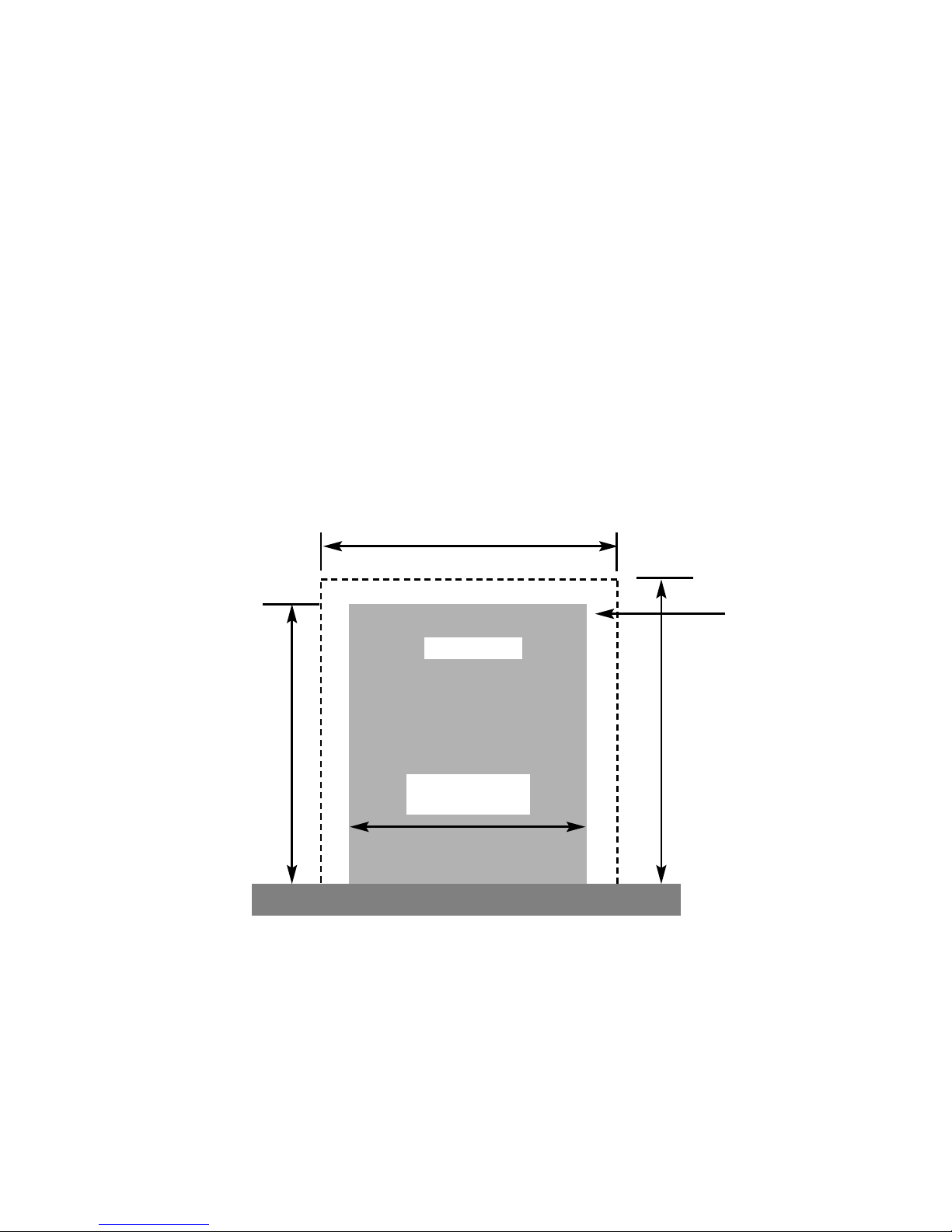
1.6 FIRE PLACE OPENING AND CHIMNEY CATCHMENT SPACE
The front opening of the fire place must be between 400 and 450 mm wide, and
between 550 and 570mm high. If the opening exceeds these dimensions then a
surround must be constructed from suitable non-combustible material to produce a
correct size opening. Any surround must be suitably sealed to the fire place to
prevent leakage. See below in figure 1.
When installing into a brick built chimney, you must ensure that there is sufficient
depth to accomodate any debris which may fall from the chimney. This depth
must be sufficient to accomodate 12 litres of volumetric space.
Fire Opening
400mm Minimum
450mm Maximum
580mm
Minimum
470mm Minimum
Fig. 1
550mm Minimum
570mm Maximum
Minimum Flat
Sealing Area
7
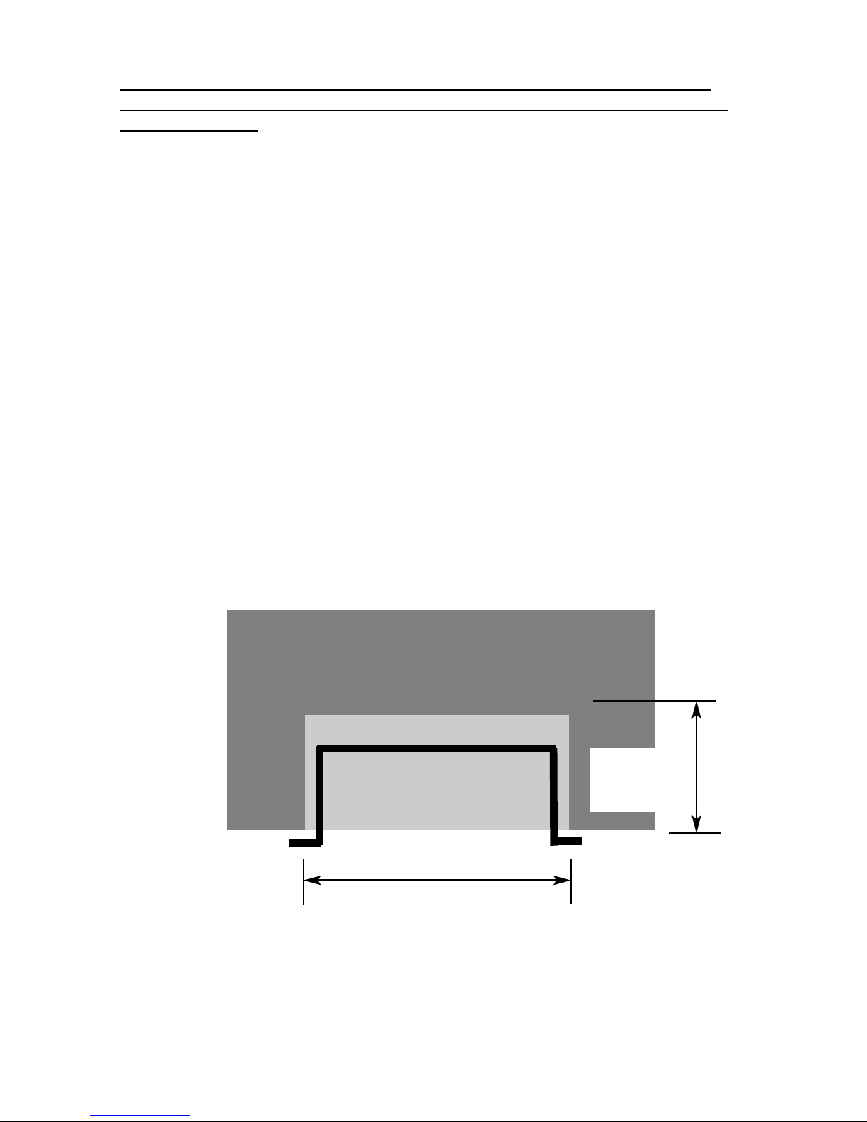
Table A - Installation Depth Requirements for a Kohlangaz Gosford being
installed into a brick built chimney, requiring 12.0 litres of debris collection
volume (figure 2)
Opening Width (mm) Minimum Depth Required (mm)
400 (minimum opening width) 298
410 392
420 285
430 280
440 273
450 (maximum opening width) 269
For example, if the appliance was to be fitted into a 400mm wide opening, the
depth required would be 298mm. See figure 2 below for explanatory diagram.
Fig. 2
8
Opening Width ( e.g. 400mm)
Depth Required
(e.g. 298mm
minimum)

1.7 FITTING TO PRE-FABRICATED TWIN WALL METAL FLUE BOXES
The appliance may be fitted to twin wall metal flue boxes conforming to the
constructional requirements of BS 715 / BS EN 1856-2, (for example the Selkirk
LFE 175 box). The box must have a minimum flue diameter of 175mm internal
and minimum internal dimensions of 300mm deep by 580mm high by 400mm
wide. There are no maximum dimensional requirements for the box. The top face
of the box must be insulated with a minimum thickness of 50mm of
non-combustible mineral wool insulation or similar material. The flue box must
stand on a non-combustible base of minimum thickness 12mm.
1.8 HEARTHS
This appliance must only be installed on to a concrete or non-combustible hearth.
The hearth material must be a minimum thickness of 13mm with the top surface at
least 50mm above the floor. The hearth must be fitted symmetrically about the fire
opening and have a minimum width of 760mm and a minimum projection of
300mm forwards from the fire opening.
1.9 SPILLAGE MONITORING SYSTEM
This appliance is fitted with an atmosphere sensing spillage monitoring system in
the form of an oxygen sensing pilot. This is designed to shut the fire off in the
event of a partial or complete blockage of the flue causing a build up of
combustion products in the room in which the fire is operated. The following are
important warnings relating to this spillage monitoring system :-
1) The spillage monitoring system must not be adjusted by the installer.
2) The spillage monitoring system must not be put out of operation.
3) When the spillage monitoring system is exchanged only a complete original
manufacturers part may be fitted. It is not possible to replace individual parts on
the pilot system on this appliance, only a complete pilot assembly (including the
thermocouple) may be fitted.
9
 Loading...