

Page 1
DRV200 - User Guide
Quickstart
1. Turn the setpoint potentiometer counter-clockwise to set the current to 0 mA.
2. Connect the pins VCC and GND to a 5 V power supply. Thanks to the very high power supply rejection of the
DRV200, a switched power supply can be used without degrading the noise performance. However, the current
limit functionality of lab power supplies can be useful.
3. (Optional) Connect a 1 Ω resistor between the LD+ and LD- pins. The current flowing across the resistor can be
measured at the IMON pin (2 V = 100 mA for DRV200-A-200, 100 mV = 1 mA for DRV200-A-40). Turn the
potentiometer clockwise until you reach the desired current.
4. Turn off the power supply and connect your laser between LD+ and LD- pins.
The DRV200 is designed for operation with floating laser diodes, i.e. that neither the anode nor the cathode is
connected to the case. If your laser anode or cathode is internally connected to the case (grounded anode or
grounded cathode), make sure that the laser case is isolated from the ground.
5. Turn on the power supply and adjust the potentiometer
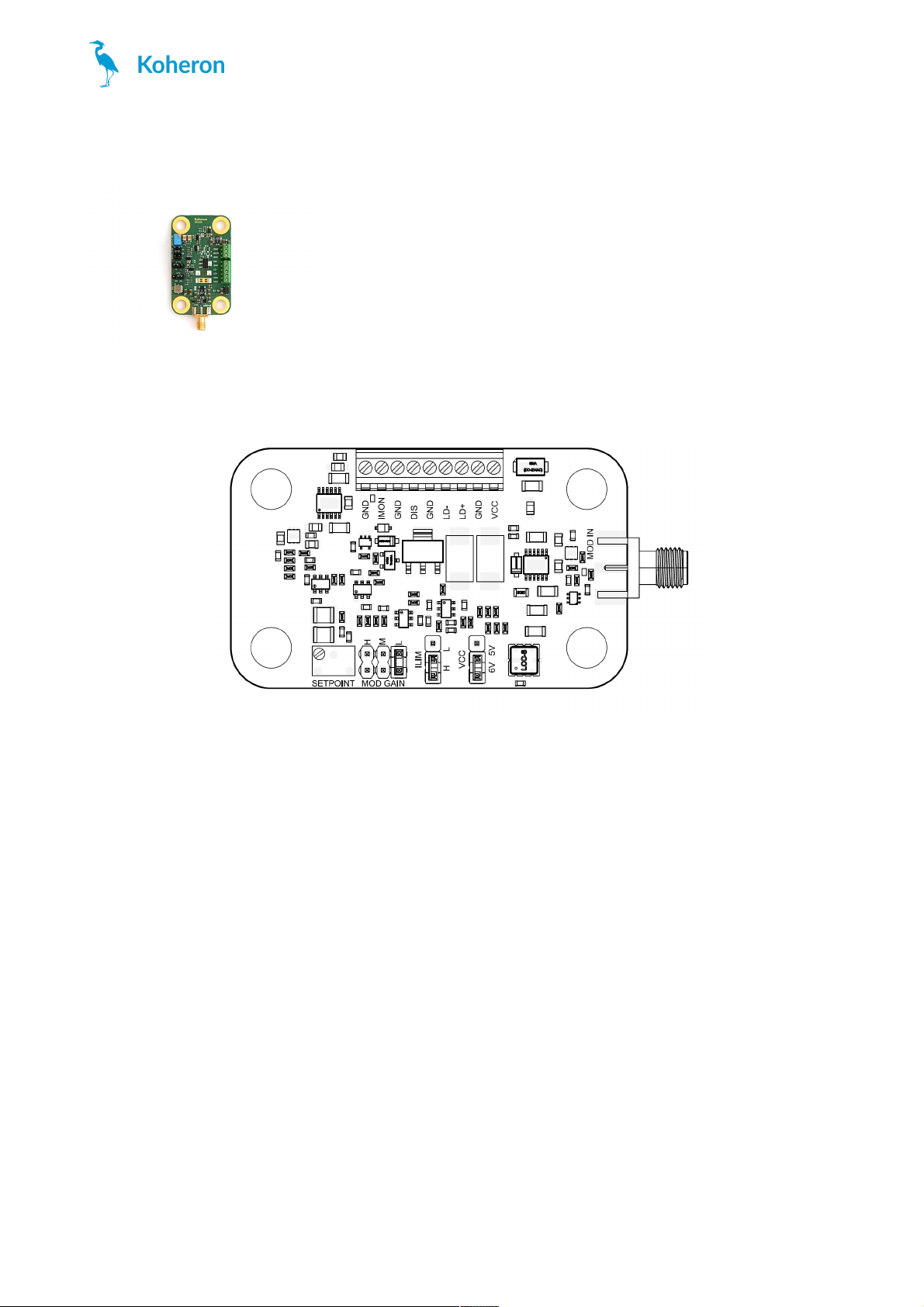
Jumper configuration
DRV200
www.koheron.com
1 / 3
Page 2

Current modulation
The DRV200 can be modulated from DC to 6 MHz using the SMA connector. The MOD GAIN jumper is used to select
between 3 modulation gains:
DRV200-A-40
Low: 200 µA/V
Medium: 2 mA/V
High: 20 mA/V
DRV200-A-200
Low : 1 mA/V
Medium: 10 mA/V
High: 100 mA/V
DRV200-A-400
Low : 2 mA/V
Medium: 20 mA/V
High: 200 mA/V
Modulation range is ±1 V and input impedance is 50 Ω.
Supply voltage selection
Set the VCC jumper according to the voltage supply used (5V or 6V). Using a 6V supply provides 1 V of extra
compliance voltage.
Current limit selection
The ILIM jumper can be used to switch between two current limit values:
DRV200-A-40
Low: 32 mA
High: 48 mA
DRV200-A-200
Low: 160 mA
High: 240 mA
DRV200
www.koheron.com
2 / 3
Page 3

DRV200-A-400
Low: 320 mA
High: 480 mA
Influence of cable length
The DRV200 offers high modulation bandwidth and some care must be taken when connecting the laser diode to the
driver for optimal performance. As a guideline, we measured the modulation response for various length of cable
between the driver and a DFB laser in TO can.
The response is measured using a DRV200-A-200 with a modulation gain set to M and a modulation signal of 500
mVpp. The cable is a pair of 22 AWG wires (0.644 mm diameter). The cable length is the length of a single wire. The
wire is always twisted except for the yellow curve.
We see that for twisted wires the peaking in the response increases slightly with the cable length, but it stays bellow 1
dB up to a length of 40 cm. However when the cable is not twisted peaking increases to more than 5 dB.
For optimal modulation performance use a twisted pair of wires with length as short as possible. The exact
modulation response depends also on the laser diode that is used.
DRV200
www.koheron.com
3 / 3
 Loading...