

Page 1
DRV200S - User Guide
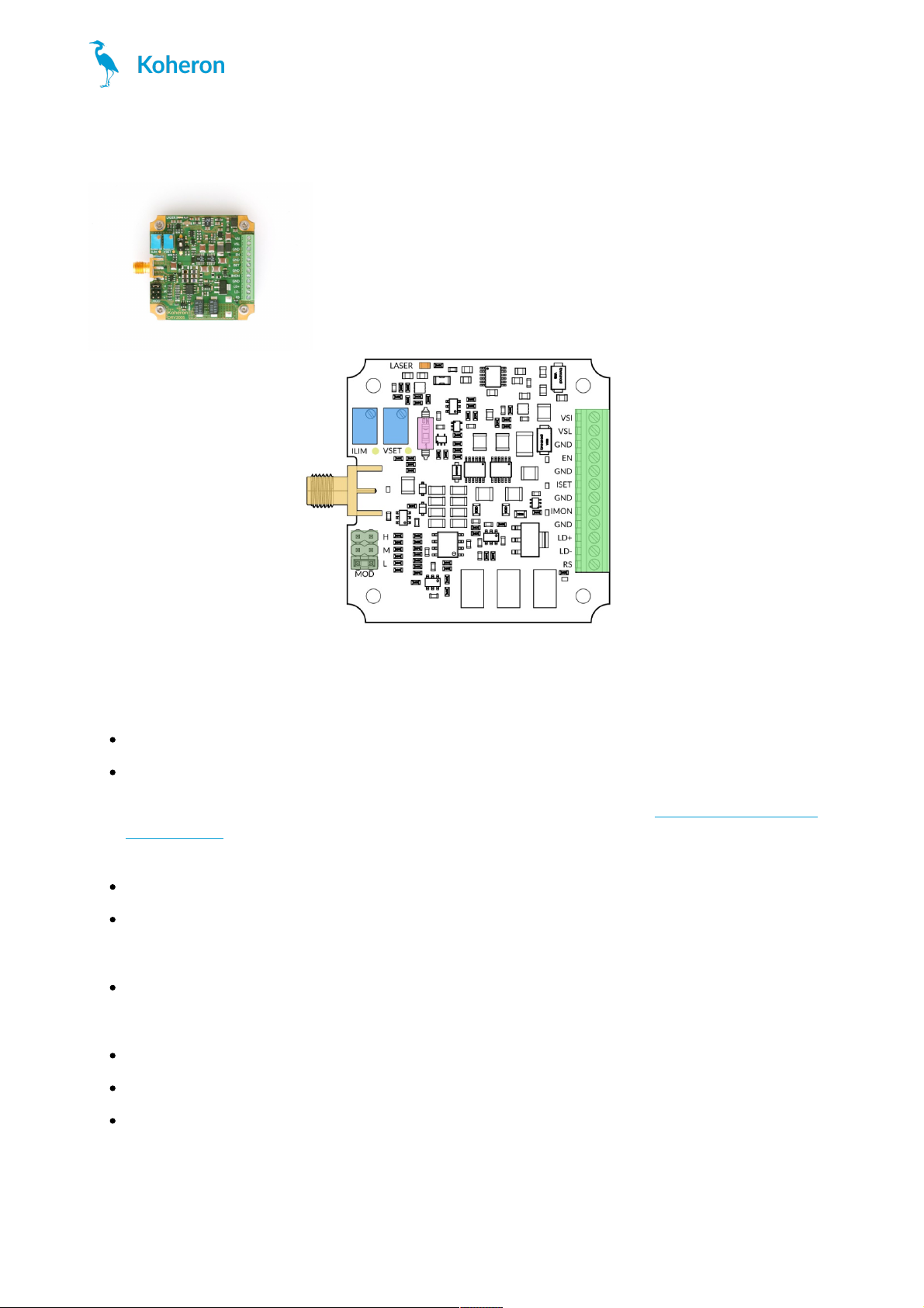
Terminal block connections
VSI: Internal supply. Connect this pin to a 5V supply. Maximum current draw is 80 mA.
VSL: Laser supply. VSL can be set between 3 V and 19 V depending on the required compliance voltage.
Maximum current draw is equal to the laser current plus 20 mA. The laser supply is internally regulated with a
linear regulator where the output voltage V
SET
is defined by the VSET trimmer (see Adjusting the compliance
voltage section). The voltage drop in the linear regulator VSL - V
SET
must be kept above 0.5 V to ensure proper
voltage regulation and below 2 V to limit power consumption.
EN: Laser Enable pin. Apply a voltage between 2.2 V and 4.5 V to enable the laser current.
ISET: Laser current setpoint input. Apply a voltage at this pin to set the laser current. The input has 2 kΩ
impedance and is filtered by a second-order low-pass filter with 10 Hz cutoff frequency. Gain is 20 mA/V for the
DRV200S-A-40, 100 mA/V for the DRV200S-A-200 and 200 mA/V for the DRV200S-A-400.
IMON: Laser current monitoring pin. The voltage at this pin is proportional to the laser current. Gain is 50
mV/mA for the DRV200S-A-40, 10 mV/mA for the DRV200S-A-200 and 5 mV/mA for the DRV200S-A-400.
Output impedance is 1 kΩ.
LD+: Laser anode pin. Connect this pin to the laser anode.
LD-: Laser cathode pin. Connect this pin to the laser cathode.
RS: Do not connect.
Adjusting the compliance voltage
DRV200S
www.koheron.com
1 / 3
Page 2

The voltage V
SET
at the test point VSET must be set according to the laser operating voltage and current:
DRV200S-A-40 safe operating area
DRV200S-A-200 safe operating area
DRV200S-A-400 safe operating area
V
SET
can be adjusted between 2.4 V and 18 V with the VSET trimmer. When the board is powered off, adjust the
voltage V
SET
by using the formula V
SET
= R
SET
× I
SET
, where R
SET
is the resistance between GND and the VSET
testpoint and I
SET
= 100 µA for the DRV200-A-40 and the DRV200-A-200 and 200 µA for the DRV200-A-400.
DRV200S
www.koheron.com
2 / 3
Page 3

Current limit
Current limit can be adjusted with the ILIM trimmer that sets the resistance RLIM between GND and the ILIM test
point.
Current modulation
The DRV200S can be modulated from DC to 6 MHz using the SMA connector. The MOD jumper allows to select
between 3 modulation gains:
DRV200-A-40
Low: 200 µA/V
Medium: 2 mA/V
High: 20 mA/V
DRV200-A-200
Low : 1 mA/V
Medium: 10 mA/V
High: 100 mA/V
DRV200-A-400
Low : 2 mA/V
Medium: 20 mA/V
High: 200 mA/V
Modulation range is ±1 V and input impedance is 50 Ω.
DRV200S
www.koheron.com
3 / 3
 Loading...