

Page 1
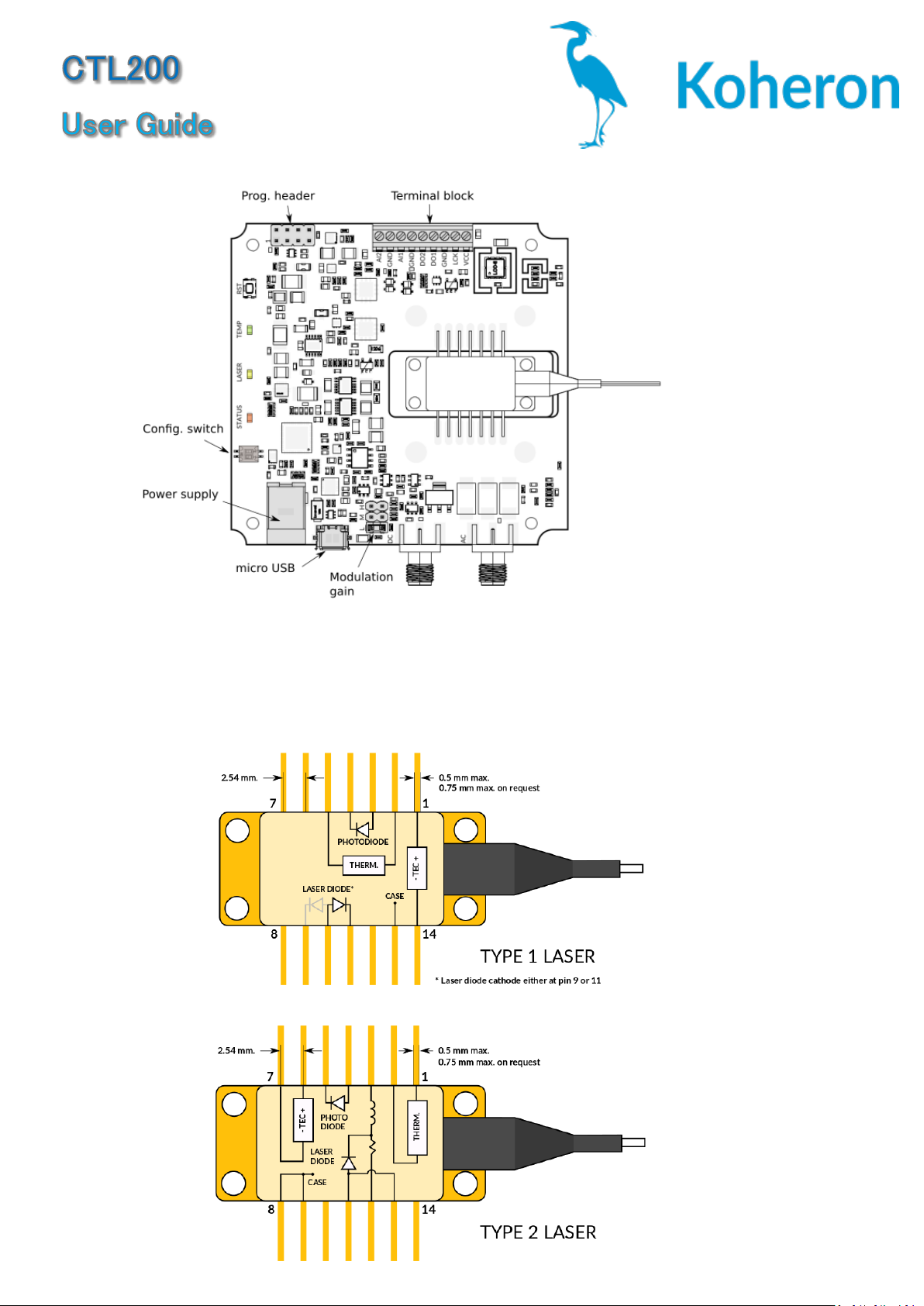
Laser connections
The CTL200-1 / CTL200-2 is compatible with Type 1 / Type 2 butterfly laser diodes. Note
that it is only compatible with floating diodes, which means that neither the anode nor
the cathode should be connected to the case.
Page 2
Power supply
The board must be supplied with the 5.9 V / 3 A power supply that comes with the CTL200.
Another power supply can be used, as long as the voltage is between 5.7 V and 6.5 V.
Serial interface
The serial interface can be accessed either via the micro USB connector or via the TX and
RX pins of the programming connector.
The serial interface is the only way of configuring the CTL200 operating parameters. Once
the configuration is done, it can be saved to the internal memory with the save command.
If the configuration switch SW1 is ON at start up, the CTL200 will load the user-defined
configuration and the serial interface is no longer needed.
The CTL200 can be controlled directly from a serial port terminal (e.g. Teraterm on
Windows) with the following configuration:
Baud rate: 115200
Parity: None
Bits: 8
Stopbits: 1
Flow control: None
Example use of the serial port terminal
>>
>>version V0.1
>>rtset 10000.000000
>>rtact 10000.023438
>>rtset 12000 12000.000000
>>rtact 11999.853516
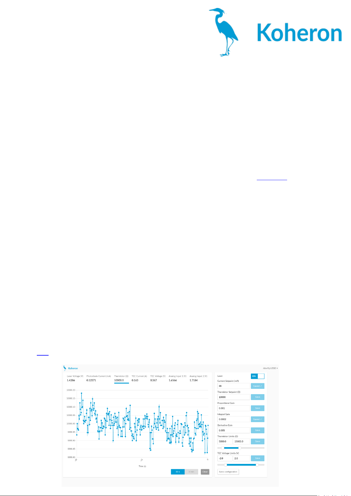
Graphical User Interface
A Graphical User Interface is available for Windows. The installer can be downloaded at
this link. The GUI provides an effective mean of tuning the PID gains of the temperature
controller.
Page 3

Control commands
lason: Should be set to 1 to enable the laser current (default value: 0)
ilaser: Laser current in mA (default value: 0.0).
rtset: Thermistor resistance setpoint in Ω (default value: 10000.0).
pgain: Proportional gain of the temperature controller (default value: 0.001).
igain: Integral gain of the temperature controller (default value: 0.0001).
dgain: Differential gain of the temperature controller (default value: 0.0005).
rtmin: Minimum thermistor resistance in Ω. Below this value, the laser is automatically
disabled (default value: 5000.0).
rtmax: Maximum thermistor resistance in Ω. Above this value, the laser is automatically
disabled (default value: 15000.0).
vtmin: Minimum TEC voltage in V (default value: -2.0).
vtmax: Maximum TEC voltage in V (default value: 2.0).
Status commands
version: Return the firmware version (e.g. V0.1)
lason: Laser status (0 when disabled, 1 when enabled)
vlaser: Laser voltage in V.
iphd: Photodiode current in mA (maximum value: 2.5 mA).
rtact: Actual value of the thermistor resistance in Ω.
itec: TEC current in A.
vtec: TEC voltage in V.
ain1: Voltage on pin AIN1 in V.
ain2: Voltage on pin AIN2 in V.
Configuration switch
Switch 1: When SW1 is ON, the user configuration is loaded at start-up. When SW1 is OFF,
the default configuration is loaded at start up.
Switch 2: SW2 is used for firmware update. It should be kept OFF for normal operation.
Status LEDs
STATUS: Always ON during normal operation
LASER: Turns ON when the photodiode current is above 10 mA.
TEMP: Turns ON when the thermistor resistance is within 1 Ω of the setpoint.
Modulation inputs
The CTL200 has two current modulation inputs available on SMA connectors:
DC modulation input for modulation between DC and 10 MHz. Modulation range is +/- 1
V. A jumper allow to choose between 3 modulation gains (200 µA/V, 2 mA/V or 20 mA/V
for the 200 mA version).
AC modulation input for modulation above 100 kHz. Modulation gain is 20 mA/V.
Page 4

Thermal management
The TEC voltage limits (vtmin and vtmax) and the thermistor resistance limits
(rtmin and rtmax) provide an effective way of protecting the laser against thermal runaway.
For reliable operation, the aluminium cooling base plate must be properly heatsunk.
 Loading...