

Page 1
CTL101 - User Guide
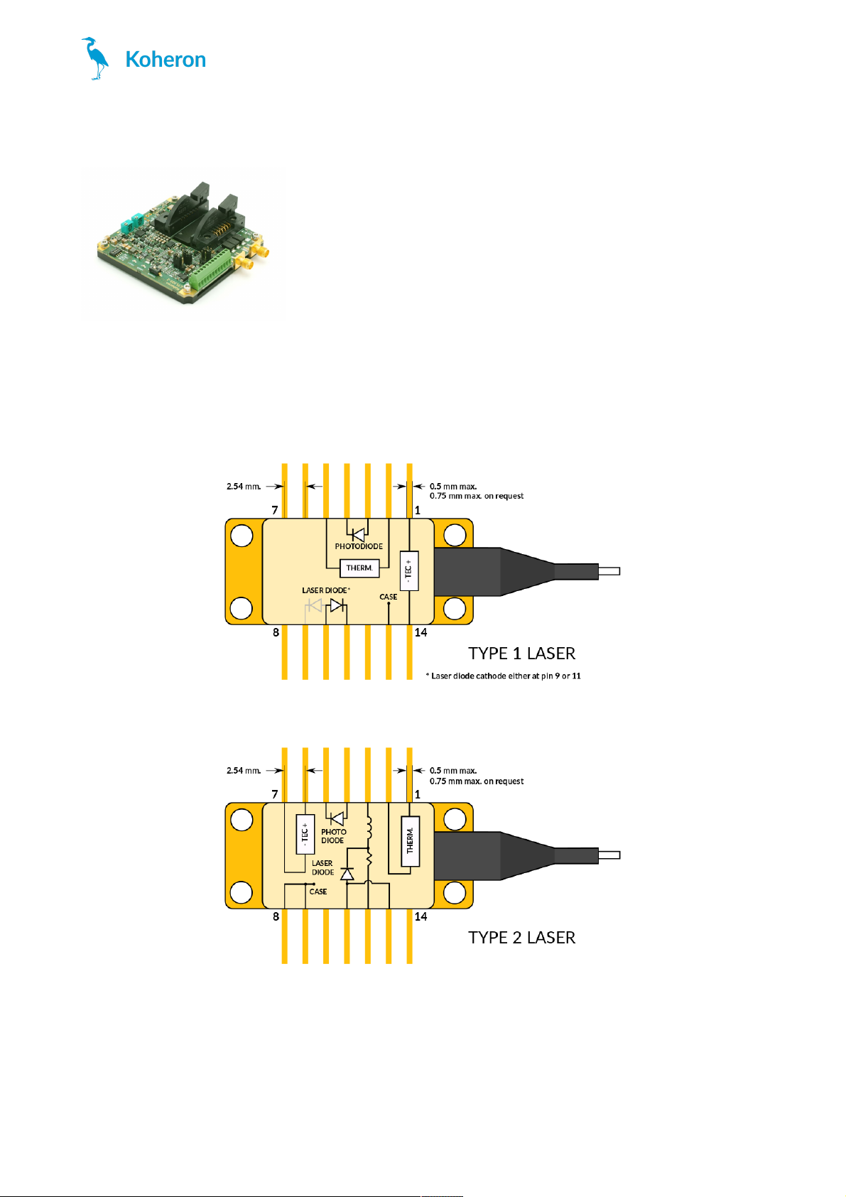
Laser connections
The CTL101-1 / CTL101-2 is compatible with Type 1 / Type 2 butterfly laser diodes. Note that it is only compatible
with floating diodes, which means that neither the anode nor the cathode should be connected to the case.
Butterfly laser type 1 pin configuration
Butterfly laser type 2 pin configuration
Quickstart
CTL101
www.koheron.com
1 / 3
Page 2
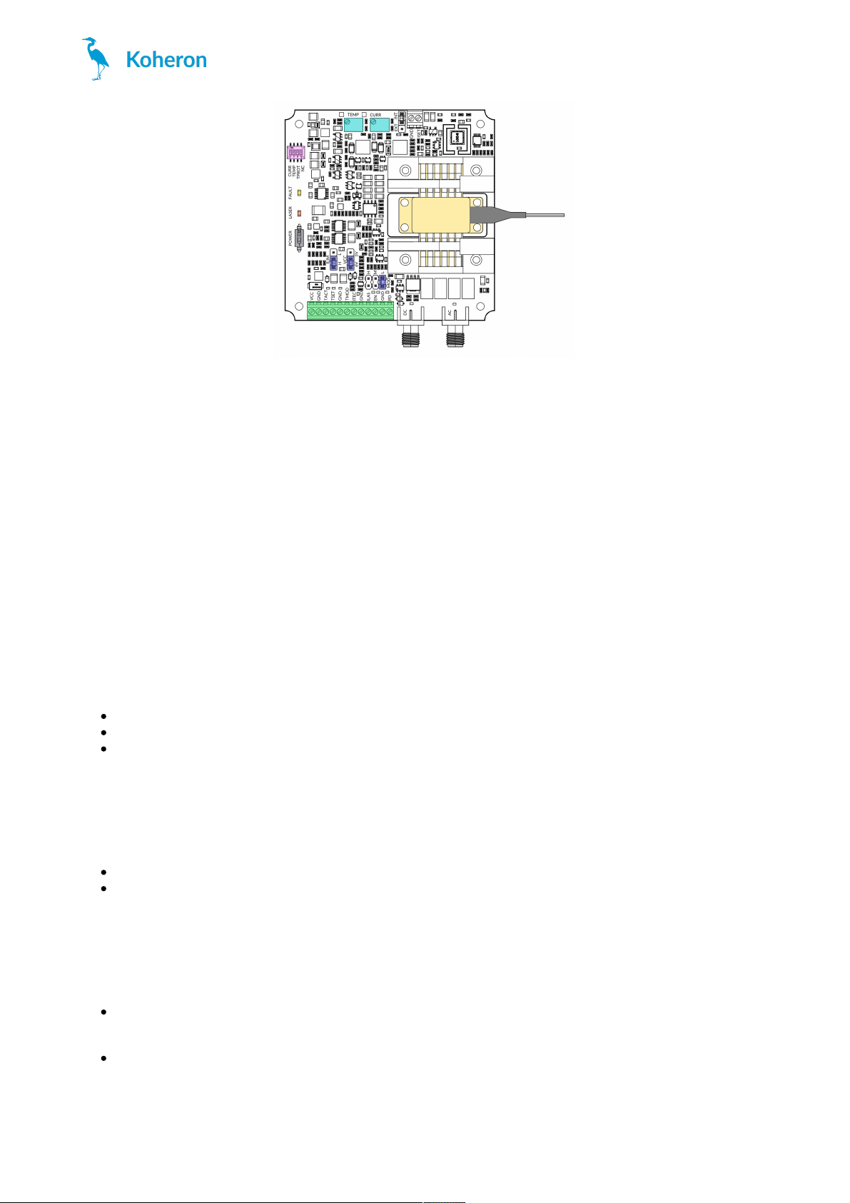
1. Make sure the laser current switch (CURR) and the TEC current switch (TEMP) are OFF. Set the TPROT switch
ON.
2. Set the VCC jumper to 5V.
3. Plug the laser diode on the ZIF socket. Make sure there is a good thermal connection between the laser case
and the base plate. Use thermal paste if necessary.
4. Power the board with 5 V on VCC pin (set the VCC jumper accordingly). The power supply must be able to
supply at least 2 A (2.5 A for the 800 mA version).
5. Set the current to 0 mA by turning the laser current trimmer (CURR) counter-clockwise.
6. Turn the POWER switch ON.
7. Adjust the temperature trimmer to get 2.5 V on the TSET pin.
8. Turn ON the TEC current switch.
9. Check that the voltage between the TSET and TACT pins converges towards zero. The laser temperature is now
stabilized at 25 °C.
10. Turn ON the laser current switch.
11. Turn the laser current trimmer (CURR) clockwise to reach the desired laser current.
Enable switch
CURR: Turn ON to enable laser current.
TEMP: Turn ON to enable TEC current.
TPROT: When this switch is ON, the laser current is automatically disabled in case of a TEC fault condition (see
FAULT LED).
LEDs
LASER: The brightness of this LED is proportional to the laser power measured on the monitoring photodiode.
FAULT: Indicates a TEC fault condition, i.e. when the TEC driver is no longer capable of cooling the laser at the
desired temperature.
Terminal block connections
VCC: Connect this pin to a 5V or 6V power supply. Using a 6V supply provides 1 V of extra compliance voltage.
The VCC jumper must be set according to the chosen power supply.
TACT: Temperature monitoring pin. The thermistor value is given by
Rth = 10 kΩ * (10 V - V
TACT
) / (5 V + V
TACT
).
The pin output impedance is 1 kΩ.
CTL101
www.koheron.com
2 / 3
Page 3

TSET: Temperature setpoint monitoring pin.
V
TSET
= V
TREF
+ (1 / 10) * V
TMOD
where V
TREF
is the voltage generated by the TEMP trimming potentiometer. The voltage V
TREF
can be tuned
between 0 and 4 V and can be measured at test point TP2. V
TMOD
is the voltage applied at the TMOD pin. The
PID controller tries to make the voltage V
TACT
equal to the setpoint V
TSET
. The pin output impedance is 1 kΩ.
ITEC: TEC current monitoring pin. The TEC current I
TEC
is given by
I
TEC
= 1 A/V * (V
ITEC
- 2.5 V)
where V
ITEC
is the voltage measured at the ITEC pin. The pin output impedance is 1 kΩ.
TMOD: Temperature modulation pin. Apply a voltage between -3 V and +3V at this pin to control the
temperature setpoint externally (see description of the TSET pin).
ILAS: Laser current monitoring pin. The laser current I
LAS
is given by
I
LAS
= G * V
ILAS
, where V
ILAS
is the voltage measured at the ILAS pin and G is 50 mA/V for the 200 mA version,
100 mA/V for the 400 mA version and 200 mA/V for the 600 and 800 mA versions. The pin output impedance is
1 kΩ.
EN: Laser Enable pin. Apply a voltage between 2.2 V and 4.5 V to enable the laser current.
PD: Output of the transimpedance amplifier that monitors the laser power. This output has 3.9 V/mA gain, a
bandwidth from DC to 20 MHz, and is terminated with a 50 Ω resistor. The actual laser power depends on the
photodiode integrated in the laser and should be calibrated by the user. The LASER LED brightness is
proportionnal to VPD.
Modulation inputs
The CTL101 has two current modulation inputs available on SMA connectors:
DC modulation input for modulation between DC and 10 MHz. Modulation range is ±1 V. A jumper allows to
choose between 3 modulation gains (2 mA/V, 20 mA/V or 200 mA/V for the 400 mA version).
AC modulation input for modulation above 1 MHz. Modulation gain is 20 mA/V.
CTL101
www.koheron.com
3 / 3
 Loading...