

Page 1

Laser connections
The CTL100 is compatible with Type 2 butterfly laser diodes. Note that is is only
compatible with floating diodes, which means that neither the anode nor the cathode
should be connected to the case.
Enable switch
1 ON: Enable laser current.
2 ON: Enable TEC current. Turn off the power supply before changing this switch.
Terminal block connections
•VCC: Connect this pin to a 5V power supply (2 A minimum). The high power supply
rejection of the current driver allows the use of a switched power supply with minor
degradation of the noise performance. At a laser current of 400 mA, the CTL100 draws 510
mA (TEC current disabled). An eFUSE protects the CTL100 against overvoltage (6.1 V) and
overcurrent (2 A).
•TACT: Temperature monitoring pin. The thermistor value is given by Rth = 10
kΩ ×(10.5V−VTACT)/(5.5V+VTACT). The output is current-limited with a 1 kΩ resistor.
•TSET: Temperature setpoint monitoring pin. VTSET=VTREF+VTMOD/10, where VTREF is the voltage
generated by the temperature trimming potentiometer. The voltage VTREF can be tuned
between 0 and 2.5 V and can be measured at test point TP2. VTMOD is the voltage applied at
the TMOD pin. The PID controller tries to make the voltage VTACT equal to the setpoint VTSET.
The output current is limited with a 1 kΩ resistor.
Page 2
•ITEC: TEC current monitoring pin. The TEC current ITEC is given by ITEC = 1
A/V × (VITEC−2.5V), where VITEC is the voltage measured at the ITEC pin. The output current
is limited with a 1 kΩ resistor.
•TMOD: Temperature modulation pin. Apply a voltage between -3 V and +3V at this pin to
control the temperature setpoint externally (see description of the TSET pin).
•ILAS: Laser current monitoring pin. The laser current ILAS is given by ILAS = 100
mA/V × VILAS, where VILAS is the voltage measured at the ILAS pin. The output current is
limited with a 1 kΩ resistor.
•DIS: Laser disable. Apply a voltage between 2 V and 5 V to disable the laser current.
•PD: Output of the transimpedance amplifier that monitors the laser power. This output has
3.9 V/mA gain, a bandwidth from DC to 50 MHz, and is terminated with a 50 Ω resistor. The
actual laser power depends on the photodiode integrated in the laser and should be
calibrated by the user.
Thermal considerations
The temperature controller dissipates a power equal to (5V−|VTEC|)×ITEC(5V−|VTEC|)×ITEC. For
reliable operation, do not dissipate more than 2.5 W in the temperature controller (derate
400mW per 10 °C above 30 °C). The power dissipation can be a problem for lasers with low
resistance Peltier element (e.g. 400 mV at 1A).
Note that you can protect your laser against over-temperature by connecting a
resistor R1 between DIS and TACT pins and a resistor R2R2 between DIS and GND pins. The
laser will shutdown when VTACT > 2V×(R2+R1+1kΩ )/(R1+1kΩ )
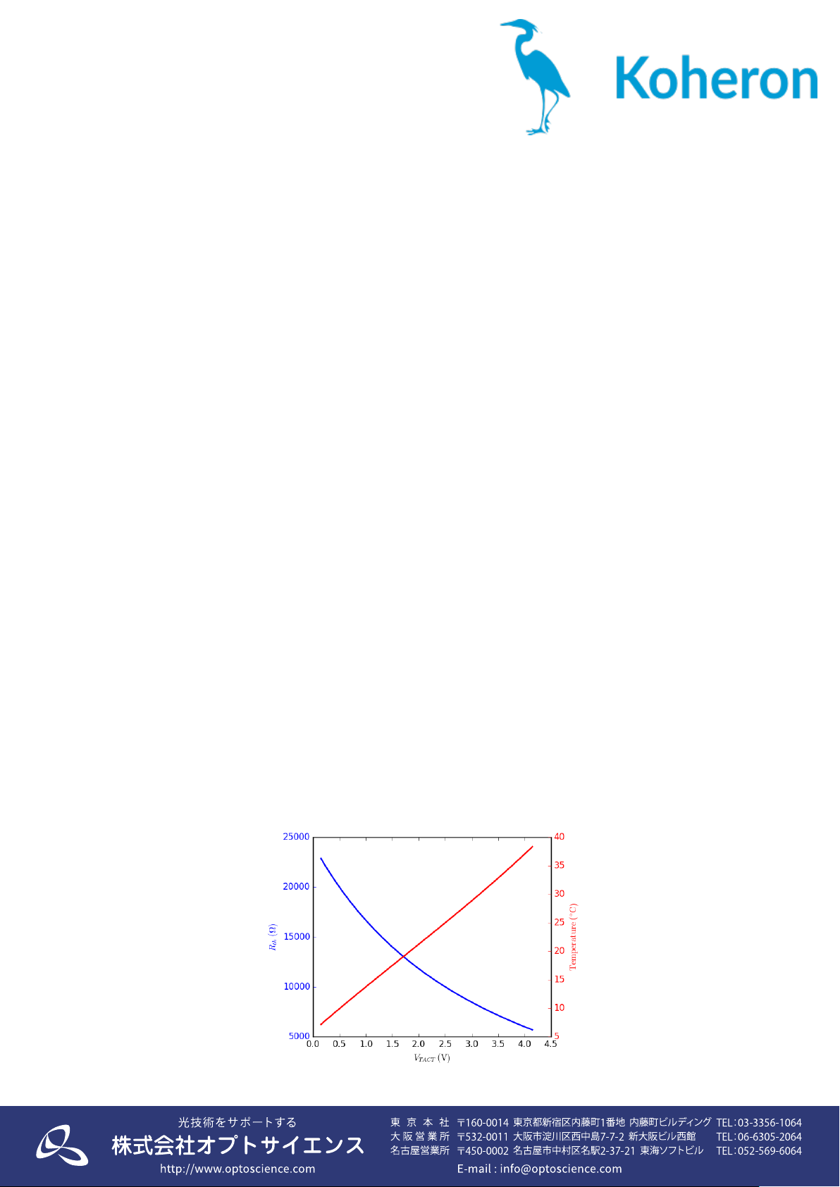
Extended temperature option
The CTL100 is also available with an extended temperature range option (7-38 °C instead of
12-25 °C). In this case, the thermistor value is given by Rth = 10
kΩ ×(8.5V−VTACT)/(3.5V+VTACT).
The gain at the TMOD pin is also increased: VTSET=VTREF+VTMOD/3.
 Loading...