


INSTRUCTION MANUAL Ver.1.0
BKUA002 Ver.1.0
PRESSURE GAUGE
Air Treatment

Temperature characteristics
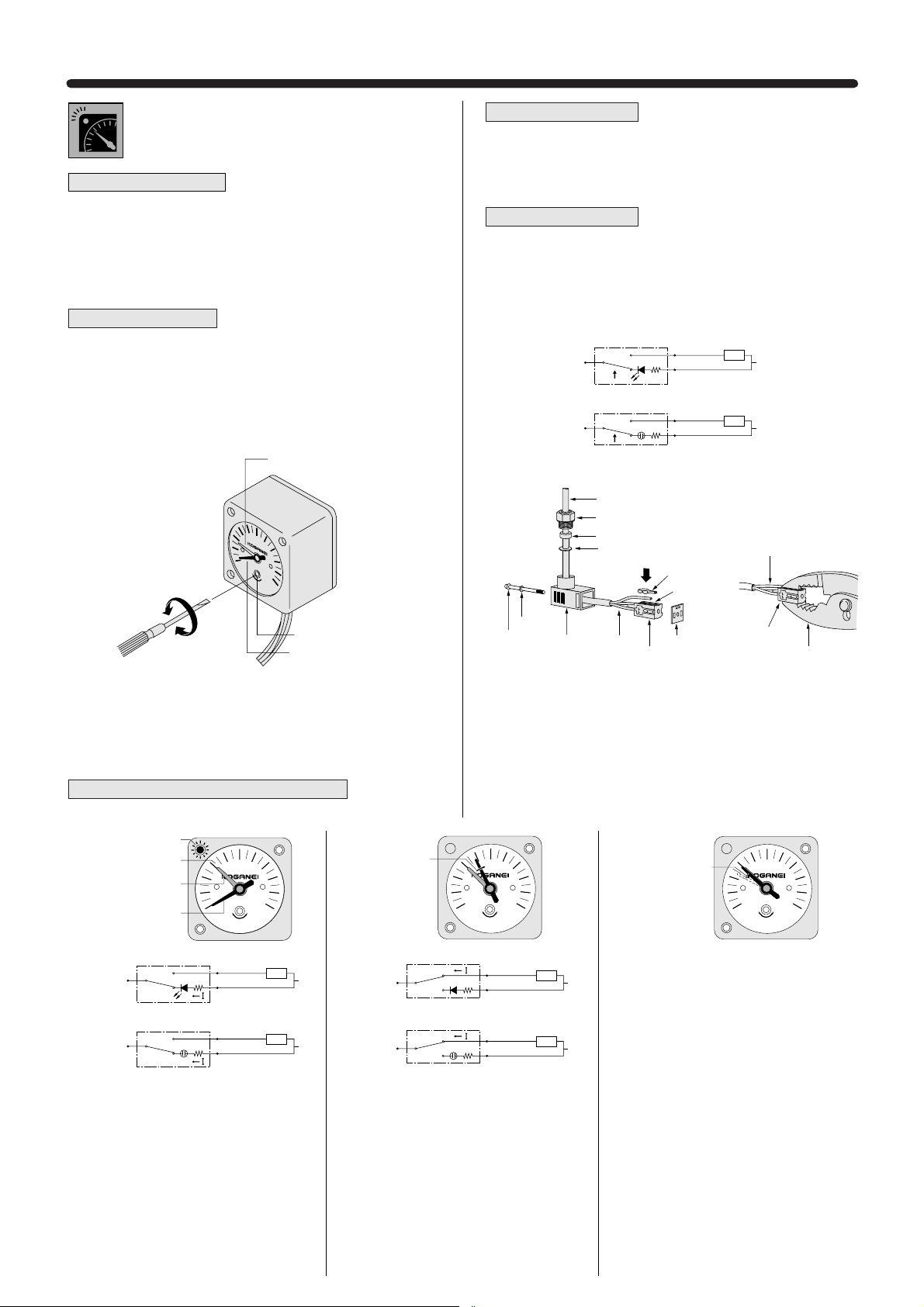
●Small Precision Pressure Gauge
1. The small precision pressure gauge is a pressure indicator
designed for more sensitive pressure measurements. Avoid use
in locations subject to vibrations or shocks.
2. The throttle valve uses an extremely small orifice for protection
from shock pressure transmitted to the Bourdon tube and other
internal devices, and is therefore sensitive to intrusions of
particles, sludge mist, and other contaminants. For the media,
use clean, dry air that has passed through a mist filter, etc.
Preset marker
●Small Precision Pressure Gauge
1. The guaranteed temperature accuracy range is 25°C±5 [77±
9°F]. Check the ambient temperature of the measurement
location before proceeding with measurement.
2. If the temperature is out of the guaranteed temperature accuracy
range, perform a pressure compensation by multiplying the
ambient temperature by the humidity coefficient 0.05% F.S./°C.
3. In performing pressure compensation, add plus or minus in
accordance with temperature characteristics, subtractinwhen
the temperature is at 30°C or higher, and adding when the
temperature is at 20°C or lower.
Example: The measured value is 0.2MPa and the ambient
temperature is 40°C (the pressure
compensation value is ±
0.00015MPa)
※(Even after performance of pressure compensation, there is an error of ±1% F.S.)
● Small Pressure Gauge,
Pressure Gauge
Preset markers can be used on the
pressure gauges G1-40 and G3-40.
Rotate the cover ring first to set the low
pressure side, and then set the high
pressure side.
P0=P1±0.00015×(T1−T2)
P
0=0.2−0.00015×10
P
0=0.1985MPa
P
0: Actual pressure (MPa)
P
1: Measured pressure (MPa)
T
1:
Guaranteed accuracy temperature (°C)
T2: Ambient temperature (°C)
4. If not performing pressure compensation, the pressure indication
accuracy value is accurate within the operating temperature
range shown on the temperature characteristics graph. Be aware
that the ambient temperature can change the indicated accuracy.
5. The graph below positions 25°C [77°F] as the standard
temperature, and shows the amount of change from the
indicated accuracy at 25°C [77°F] required for the ambient
temperature to come within the operating temperature range, in
terms of percent of full scale (F.S.).
6. The temperature characteristic lines shown in the graph below
are representative examples only. Individual products will exhibit
some variance from these lines in terms of characteristics.
7. The chain line shows the indicated accuracy ±1% F.S.,
while the dotted line shows the amount of change required
for the ambient temperature to come within the operating
temperature range, calculated using the humidity coefficient. The
figures within the framed area show the compensation range.
-5
+3
+2
+1
0
-1
-2
-3
010 25 40 6050
Ambient temperature
Operating temperature range
% F.S. indicated accuracy
Low pressure
side marker
High pressure
side marker
Cover ring
176
Small Pressure Gauge, Pressure Gauge, Panel
Mounting Pressure Gauge
Small Precision Pressure Gauge, Vacuum Gauge
Mounting and piping
● Small Pressure Gauge, Pressure Gauge, Small Precision
Pressure Gauge, Vacuum Gauge
1. While any mounting direction is acceptable, install a throttle
mechanism, etc., When mounting between a valve and actuator,
or other location where pressure fluctuation can be intense.
2. When mounting and piping a pressure gauge, never grab the
pressure gauge body for the purpose of tightening. To tighten,
always use a wrench on the hexagonal or square section of the
connection port. The tightening torque should be at 294.2N・cm
[26.0in.・lbf] or less.
● Panel Mounting Pressure Gauge
■ Panel Mounting Pressure Gauge (GP1-40, GP-40,
GPV-40)
1. When mounting the panel mounting pressure gauge on a panel,
machine the mounting holes in accordance with the panel cut
dimensions. (See the panel cut dimensions)
2. Since the panel mounting pressure gauge in its packaged
condition already has the pressure gauge assembled into the
panel mount assembly, always remove the mounting ring from
the assembly and then mount on a panel for use.
3. When mounting on a panel, first align the convex section of the
back side of the panel mounting case flange to the small hole
used for positioning on the panel cut hole (see Figure 1).
4. The tightening torque for the mounting ring used to secure
the panel mounting case in position should be 980.7N・cm
[86.8in.・lbf] or less.
5. If removing the pressure gauge itself from the panel mounting
case, first remove the mounting ring, and then pull up on the tab
located on the bottom of the panel mount case. The pressure
gauge can now be easily removed by pushing it out. Be aware
that forcibly attempting to remove the pressure gauge without
first pulling on the tab could damage the convex section inside
the tab that is used to prevent falling. (see Figure 2)
■ Panel mounting assembly (PM-40)
If purchasing the pressure gauge and panel
mounting assembly separately, take the
following steps when combining them to use as
the panel mounting pressure gauge.
1. Remove the mounting ring from the panel
mounting case, and insert the square part of
the pressure gauge connection port into the
square part at the bottom of the case.
2. When inserting, check that (1) the two set screws on the back of
the pressure gauge case are on the lower side, and (2) two set
screw holes are found on the bottom of the panel mounting
case's square part. After confirming the above two items, push in
the pressure gauge.
3. With the unit in the inserted position, check to see that the
convex section at the bottom of the panel mounting case that is
used to prevent falling is inserted into the mounting hole (φ2.3)
[0.091in.] at the bottom of the pressure gauge case. If the
pressure gauge and panel mounting case have been assembled
correctly, the insertion tab will snap smoothly into place. If it does
not go in smoothly, lift up on the tab and the unit should then
slide in easier (see Figure 3).
Figure 1
Figure 2 Figure 3
(PM-40)
Handling Instructions and Precautions
Convex portion
Panel mounting case Panel cut hole
Small hole used
for positioning
Convex portion
(opposite side)
Insertion tab
φ2.3 Mounting hole

Materials (body) Plastic (PPS)
Mass g [oz.] 7 [0.25]
°C [°F] 5
〜60 [41〜 140]
Maximum operating pressure MPa [psi.]
0.93 [135]
Outer diameter
φ20mm [0.79in.] (Scale plate outer diameter)
Accuracy F.S.±4%
Pressure indication range
MPa [psi.]
0〜1.0 [0 〜145]
Port size R1/8 φ6 plug-in
Media Air (Conditioned air, max. 5μm)
G1-20A G1-20D G1-20DPL
Item
Model
26
13
8
21.8
11.5
R1/8
(Width across flats)
10
.5
0
1.0
G1-20A, G1-20D, G1-20DPL
Symbol Specifications
Dimensions of Small Pressure Gauges (mm)
● Pressure applied sections are made of beryllium copper,
for improved durability.
● A new plug-in type has been added, for snap-in
connection to quick fittings.
10
R1/8
18.75
13
13
5.75
31.5
34.8
φ21.8
.5
0
1.0
(Width across flats)
Order Codes
Direction/method of piping
A
Bottom piping
D Back piping
DPL Back piping plug-in
※ For handling instructions and precautions, see p.176.
G 1 20
Pressure gauge
Outer diameter
20mm [0.79in.]
Pressure indication range
1
Standard specification 1MPa [145psi.]
G1-20A
34
3
10 21
5
φ6
90
φ21.8
.5
0
1.0
G1-20DPL
G1-20D
Remark: The small pressure gauge uses a spiral Bourdon tube.
A multiple number of scale plates are used to compensate the spiral Bourdon tube’s
tolerance. Comparison of two or more scale plates can result in scale angle variation of up to
45°.
SMALL PRESSURE
GAUGES
Operating temperature range
(atmosphere and media)

Materials
Bourdon tube Brass
Flats of nipple section
Brass
Case ABS
Mass kg [lb.] 0.09 [0.20]
°C [°F] 5
〜
60
[41
〜140]
Maximum operating pressure
MPa [psi.]
0.93 [135] 0.25 [36] 0.55 [80]
Outer diameter mm [in.] 40 [1.57]
Accuracy
F.S.
±3%
Pressure indication range
MPa [psi.]
0〜1.0 [0 〜145] 0〜0.3 [0 〜44] 0〜 0.6 [0 〜 87]
Port size
R1/4 (M5
×0.8)
Media Air
Item
Model
G1-40 G3-40 G6-40
G1-40, G3-40, G6-40
Symbol Specifications
Dimensions of Pressure Gauges (mm)
Order Codes
Outer diameter
40
Outer diameter 40mm [1.57in.]
※ For handling instructions and precautions, see p.176.
G
40
Pressure gauge
Pressure indication range
1
Standard specification 1MPa [145psi.]
3 Low pressure specification 0.3MPa [44psi.]
6 Low pressure specification 0.6MPa [87psi.]
G1-40
G3-40
G6-40
PRESSURE GAUGES
Operating temperature range
(atmosphere and media)
0.6
0.4
0.2
0.8
MPa
0
1
φ42.5
26.5
(40)
46
(6)
R1/4
M 5×0.8
14
(Width across flats)

Materials (Case/mounting ring) Plastic (ABS/POM)
°C [°F] 5
〜
60
[41
〜140]
Maximum operating pressure
MPa [psi.]
0.93 [135] 0.25 [36]
Outer diameter mm [in.]
}
53 [2.09]
Accuracy
}
F.S.
±3%
Pressure indication range
MPa [psi.]
0〜1.0 [0 〜145] 0〜0.3 [0 〜44]
Port size R1/4 (M5×0.8)
Media Air
Item
Model
GP1-40 GP3-40
GP1-40, GP3-40
Symbol Specifications
Order Codes
Dimensions of Panel Mounting Pressure Gauges (mm)
● Compact and panel-mounted standard pressure gauges.
● Equipped with mechanism for preventing pressure gauge
from falling from its case.
● Equipped with quick fittings for fast piping installation.
Outer diameter
40
Outer diameter 40mm [1.57in.]
※ For handling instructions and precautions, see p.176.
GP 40
Panel mounting pressure gauge
Note: Panel mounting pressure gauges are supplied with quick fittings.
(
φ4 straight type and elbow type) .
Pressure indication range
1
Standard specification 1MPa [145psi.]
3 Low pressure specification 0.3MPa [44psi.]
Mass kg [lb.]
0.106 [0.234]
(28) 18
46
7
3.5
φ4 2.5
φ53
R1/4
14
Case
Mounting ring
M48×2
M5 ×0.8
26
φ48.5
R3
Width across flats
Panel cut dimensions
Convex portion
Insertion tab
(Concave
portion)
0.8
0.2
0
1
0.6
0.4
MPa
PANEL MOUNT
PRESSURE GAUGES
Operating temperature range
(atmosphere and media)

Mass
g [oz.]
90 [3.17] 106 [3.74]
Plastic (ABS/POM)
Body (pressure gauge case) SPCC
Shock resistance m/s
2
[ft./sec.2] 9.8 [32] max.
Temperature coefficient 0.05% F.S./°C
Guaranteed temperature accuracy range
25±5°C [77 ±9°F]
Minimum measurement unit
0.005MPa [0.7psi.]
Pressure indication accuracy
F.S.
±1% (0.003MPa [0.44psi.])
Operating temperature range
°C [°F] –5〜 60
[23
〜140]
Maximum operating pressure
MPa [psi.]
0.25 [36]
Pressure indication range
MPa [psi.] 0〜0.3 [0 〜44]
Port size R1/4 (M5×0.8)
Operation type Bourdon tube
Media Air
Item
Model
G3P-40 GP3P-40
G3P-40, GP3P-40
Symbol
Order Codes
Specifications
Dimensions of Small Precision Pressure Gauges (mm)
● Compact, yet assures full scale pressure indication
accuracy of
±1%.
● Can also be used as a panel mounting pressure gauge.
● Mechanical operating life of 200,000 full scale (FS)
operations (with built-in throttle valve).
Outer diameter
40
Outer diameter 40mm [1.57in.]
(Scale plate)
Blank NO throttle valve
S With throttle valve
Note1
Notes 1.Throttle valves are to be sold separately.
2. Panel mounting type is supplied with quick fittings.
(
φ4 straight type and elbow type).
※ For handling instructions and precautions, see p.176.
※ For the panel cut dimensions, see p.173.
G3P – 40 –
Small precision pressure gauge
Pressure indication range 0.3MPa [44psi.]
Outer diameter
40
Outer diameter 40mm [1.57in.]
(Scale plate)
Blank NO throttle valve
S With throttle valve
Note1
GP3P – 40 –
Small precision pressure gauge
Panel mounting type
Note2
Pressure indication range 0.3MPa [44psi.]
M4
Wire
(
φ0.4
)
7
1.5
φ0.5
60°
Throttle valve
Additional parts
(To be ordered separately)
M031
MPa
CLASS
1.0
0
0.05
0.1
0.15
0.2
0.25
0.3
Orange area
0〜0.005MPa
Orange area
0.25〜0.3MPa
[36〜44psi.]
[0〜0.7psi.]
Markers
SMALL PRECISION
PRESSURE GAUGES
Case/mounting ring
(panel mount assembly)
Materials
φ2.3 Hole
(For insertion
tab)
Cover
φ42.5
7±0.1
φ42±0.2
26.8
(
47.5
Flats of nipple section
(nickel plated)
14
Width
across
flats
12 R1/4
20.7
)
M5×0.8
Depth 8
□14
Throttle valve
mounting position
φ55
φ53
M48×2
3.5
φ42.5
(
)
47.5
26.8
7
Convex
section
20.7
Insertion tab
Mounting ring
Case
M5×0.8
Depth 8
R1/4
14
Width across flats

Operating temperature range
°C [°F] 5〜60 [41〜140]
Accuracy
F.S.
±
3%
Pressure indication range
kPa [in.Hg]
0〜−100 [0 〜−29.54]
Media Air
Item
Model
GV-40-01 GV-40, GPV-40
GV-40/GPV-40
Symbol Specifications
Order Codes
Dimensions (mm)
GV 40
Vacuum gauge
Outer diameter
40
Outer diameter 40mm [1.57in.]
Mass kg [lb.]
0.08 [0.18] 0.09 [0.20]
Port size
R1/8 (female thread M5
×0.8) R1/4 (female thread M5× 0.8)
20
40
60
80
100
0
−
kPa
46
26.5 19.5
12
(6)
φ
42.5
□14
R1/4
M5
×0.8
Depth 5
Port size
Blank
R1/4
01 R1/8
Non-ion specification
Blank
Standard specification
NCU Non-ion specification
GPV 400
Panel mounting vacuum gauge
※ For handling instructions and precautions, see p.176.
※ For the panel cut dimensions, see p.173.
Outer diameter
40
Outer diameter 40mm [1.57in.]
20
40
60
80
100
0
−
kPa
44
26.5 17.5
10
(4)
φ
42.5
□14
R1/8
M5
×0.8
Depth 5
GV-40-01
GV-40
20
40
60
80
100
0
−
kPa
(28) 18
46
7.5
3.5
φ4 2.5
φ53
R1/4
14
Width across flats
M48×2
M5 ×0.8
Insertion tab
Case
Convex
section
Mounting ring
GPV-40
VACUUM GAUGES

Handling Instructions and Precautions
●Pressure gauges with electronic switches
xPrecautions
D : Reverse current protection diode for power supply
Tr : NPN output transistor
ZD: Zener diode for surge voltage absorption
Power supply
・If using a commercial switching regulator for the power supply,
always ground it with a frame ground (F.G.) terminal.
・Avoid using the product while it is in a transitory state (about 0.5sec)
immediately after the power supply has been switched on.
・For direct current power supply, always use an insulated
transformer. Use of an autotransformer (single-winding transformer)
could damage the product and the power supply.
・If surges appear in the power supply, connect a surge absorber to
the source of the surge.
Input/output
・Use surge protection when connecting the inductive loads such as
DC relays to the load.
Wiring
・Avoid wiring parallel to high voltage lines or power lines, or use in
the same wiring conduits. Induction could cause erratic operation.
・Always shut off the power supply before performing wiring work.
・Keep wiring lengths as short as possible to avoid electric noise
problems.
Environment
・When using equipment that could be sources of electric noise (such
as switching regulators, inverter motors, etc.) around the sensor
installation area, ground them with an equipment’s frame ground
(F.G.) terminal.
・Avoid use in steamy or dusty locations, or in locations that are
directly subject to dripping water.
・The product cannot be used when the media or the ambient
atmosphere contains any of the substances listed below.
Organic solvents, phoshate ester type hydraulic oil, sulphur dioxide,
chlorine gas, or acids, etc.
Detection
・Do not put wires or other foreign objects inside the pressured area.
・This product is for use with non-corrosive gases. Be aware that it
cannot be used with liquids or with corrosive gases.
Mounting
・Always thoroughly blow off (use compressed air) or air blowing the
tubing before piping. Be careful to prevent chips, sealing tape, or
rust, etc., generated during plumbing from entering into the pipes.
・When connecting a fitting to a piping connection port, mount by using
a wrench on the hexagonal section of the port. The tightening torque
for R1/4 (male thread) should be 20N
・m [14.8ft・lbf] or less, and for
M5
×0.8 (female thread), 2.0N・m [1.48ft・lbf]or less.
・Never perform tightening on any other section.
Setting
・Use a setting value that provides plenty of margin for the operating
ambient temperature, power supply, voltage, and other conditions.
cBody mountingzInput/output circuit diagram
14mm wrench
bError indication
vMounting parts for panel mounting, and
protective front cover
●If the LED indicates as shown below, it means that over
current is flowing to the load, and output has short-circuited.
First, shut off the power supply, and then check the load and
output.
Short-circuit error
EG120 EG110
Panel plate
Mounting body
Pressure gauge
Protective front cover
(Sold separately)
Mounting holder
Groove on panel mounting body
1)
2)
3)
4)
1) Mount from the
front of the panel
hole, and insert the
mounting body.
2) Insert the pressure
gauge from the
back of the
mounting body.
3)
From the back of
the position shown
in 2) above, insert
the mounting holder
into the groove on
the mounting body.
4) Set the protective
front cover sold
separately.
※ To remove, use a screwdriver, etc.,
to perform the above mounting
procedure in reverse steps, and
remove the mounting holder.
●As the mounting screws for the piping connection port are the
R1/4 tapered thread or the M5 female thread, various
commercial fittings can be used.
●For direct mounting on piping, use a 14mm wrench on the
hexagonal section, do not exceed a torque value of 20N
・m
[14.8ft
・lbf]. Do not use the wrench on the body case.
When the M5 female thread is used, do not exceed a torque
value of 2.0N
・m [1.48ft・lbf].
D
Tr
Main circuit
Note: When the mode switching input line is open, the output is NO.
+V: Brown
Load
100mAMAX.
External wiring exampleInternal circuit
Note
DC12〜24V
±10%
Output: Black
ZD
0V: Blue
Mode switching input (for output operations switching):
Pink
When the mode switching input line is closed, the output is NC.

Order Codes
Additional parts (to be ordered separately)
EG1 - -
Operating pressure range
10
: For vacuum 0〜−101kPa
[0
〜−14.6psi.]
20 : For positive pressure 0〜1MPa
[0
〜145psi.]
21 : For positive pressure 0〜100kPa
[0
〜14.5psi.]
Pressure gauge with
electronic switches
Panel mounting parts
Blank
: No panel mounting parts
P : With panel mounting parts
Protective front cover
Note
Blank : No protective front cover
K : With protective front cover
Note: The protective front cover may be selected only when the panel
mounting parts are selected. The protective front cover cannot by
itself be mounted on the pressure gauge with electronic switches.
Panel mounting
parts
Protective front
cover
PM100 KB100
Reliably measures the pulsating pressure in
locations that the conventional Bourdon tube
pressure gauge has always had difficulty with,
and without worries about breakage.
The pressure gauge comes equipped with an
LED analog indication using a semiconductor
pressure transducer.
The electronic mode, without any mechanical
moving parts, assures longer operating life,
better reliability, and higher precision than the
Bourdon tube pressure gauge.
Front side
Rear side
EG110, EG120, EG121
Connection port
R1/4
Inside M5×0.8 (female thread)
Pressure inidcator (red)
Can also inidicate short-circuit errors.
Pressure setting indicator
(interlocked with pressure
setting dial)
All set when the dial needle aligns
with the desired setting.
Power supply inidicator
(red)
Pressure setting dial
Can easily set the pressure even
when the power supply is OFF.
Operation indicator (red)
Lights up when output is ON.
Secondary
pressure indication
Main
pressure indication
1/2DOT indicator (green)
Displays half of the pressure
indication scale.
Cable
Plastic case
PRESSURE GAUGES WITH
ELECTRONIC SWITCHES

Specifications
178
Performance Rating
●Pressure gauges with electronic switches
Item
Rated pressure range
Pressure setting range
Pressure indicator
Operation indicator
Power supply indicator
Proof pressure
Applicable media
Voltage
Consumption current
Output
Pressure sensitive element
Power supply voltage fluctuation
Non-linearity
Hysteresis
Repeatability
Temperature characteristics
Setting indicator accuracy
Response time
Operating ambient temperature
Operating ambient humidity
Protective structure
Vibration resistance
Shock resistance
Dielectric strength
Insulation resistance
Noise resistance
Grounding method
Port size
Front case, rear case
Front name plate
Connection port
Cable
Mass
Indicator lamp
Environment
Structure/ Materials
Model
Type Positive pressure
100kPa type
EG121
0〜100kPa [0〜14.5psi.]
10
〜90kPa [1.5〜13.1psi.]
1MPa type
EG120
0〜1.0MPa [0〜145psi.]
0.1
〜0.9MPa [14.5〜131psi.]
Vacuum
EG110
0〜−101kPa [0〜−14.6psi.]
−10〜−90kPa [−1.5〜−13.1psi.]
Red LED: Bar display indication: Positive pressure type→Clockwise rotation, Vacuum pressure type→Counterclockwise rotation
Green LED: 1/2 dot display Indication cycle: 10ms or less
Red LED (when output is ON, lights up)
Red LED (when power supply is ON, lights up)
490kPa [71psi.] 1.47MPa [213psi.]
Air or non-corrosive gas
DC12
〜24V±10%, ripple tolerance P-P ±10% or less
40mA or less
NPN transistor open collector (equipped with short-circuit protection function)
●
Maximum inrush current 100mA●Applied voltage DC30V max.●Residual voltage 1V max. (inrush current 100mA) / 0.4V max. (inrush current 16mA)
Output operation NO, NC (selectable by using the mode switching input line)
Semiconductor type
±1% F.S. or less
±2% F.S. or less
5% F.S.
±1% F.S. or less
±5% F.S. or less (at temperature range of 0〜50°C [32〜122°F], as reference point 25°C [77°F])
±2.5% F.S. or less (at median value)
10ms or less
0〜50°C [32〜122°F], In storage : −10〜60°C [14〜140°F] (without condensation or freezing)
35
〜85% RH
IP40 (IEC144)
10
〜150Hz (total amplitude 0.75mm [0.03in.] ), 2 hours in each of the XYZ directions (de-energized)
98m/s
2
[10G], 3 times in each of the XYZ directions (de-energized)
AC1000V one minute (between charging part and case)
20MΩ or more (at DC500V megger)
●Power supply line 240V or more ●Radiation 300V or more (in a pulse width 0.5μs by noise simulator)
Floating
R1/4, with M5
×0.8 female thread inside
PBT
PC
Brass (nickel plated)
0.18SQ, 4-lead, Cabtyre cable
φ3.7 [0.146in.], 0.5m [1.6ft.]
85g [3.0oz.]
〔 〕

Dimensions (mm)
●EG1□-□
●Protective front cover
Drawings for panel mounting parts
●Cut panel dimensions (mm)
Notes:1. The mounting plate thickness should
be 1 to 3.2mm.
2. The cut panel dimensions are
45
+0.6
0
×
45
+0.6
0
mm.
3. If mounting in a series, space the
units at intervals of the value shown in
the figure above or greater.
4. Conformity
DIN43700
Pressure indicator
(Red)
Pressure indicator
(Red)
Power supply indicator
(Red)
Operation indicator
(Red)
Connection port R1/4
M5×0.8, Depth: 6
40
14
40
30
54
(48) (6)
13
● EG120, EG121 front display
● EG110 front display
Pressure setting indicator
Pressure setting dial
1/2 DOT
Indicator
(Green)
Operation
indicator
(Red)
1/2 DOT
Indicator
(Green)
φ3.7 cabl e 0.5m
Plastic case
48
4
10.5
51
48
55.4
51.2
51.2
9.5
8
70
70
45
+
0.6
0
45
+
0.6
0

ON
OFF
0
(Atmospheric pressure)
Set pressure
High vacuum (vacuum type)
High pressure (positive pressure type)
(5%F.S)
Pressure
ON
OFF
0
Set pressure
Hysteresis
Operating Pressure Settings
2) Pressure setting: The pressure setting uses (1) the pressure setting dial to move (2) the pressure setting
indicator to align to (3) pressure scale.
3) Output operation
Operation parts
●EG120
●EG110
NO type
NC type
1) Pressure indication: The red LED bar indication has a lower resolution that is easy to read. In addition,
the green LED “1/2DOT” offers pressure indication at higher resolution.
● (Example) EG120 ● (Example) EG110
()
Open : NO type
GND connection : NC type
Pressure setting dial
Pressure scale
(MPa)
0.2
0.4
0.6
0.8
1.0
Pressure setting indicator
(2)
(1)
(3)
20
40
60
80
Pressure scale (kPa)
Pressure scale
(−kPa)
20
4060
80
●EG121
Indicated pressure:−40kPa
−42.5kPa
−45kPa
20
40
60
80
20
40
20
40
Green LED lights up
Indicated pressure:0.8MPa 0.825MPa 0.85MPa
0.2
0.4
0.6
0.8
1.0 1.0 1.0
0.6
0.8
0.6
0.8
Green LED lights up
To set the pressure, insert a small screwdriver into the pressure
setting dial, and rotate the dial.
※ To switch the output operation, change the mode
switching input line.
Status for mode
switching input line
PRESSURE GAUGES
M
P
a
0
.1
0
.
2
0
.
3
0
.
4
0
.5
0
.
6
0
.
7
0
.8
1
0
.
9
0
Regulating pressure indicator (red)
Pressure regulation screw
Pressure indicator (black)
High
Low
Handling Instructions and Precautions
Pressure gauges with built-in switch
1. While any mounting direction is acceptable, install a throttle
mechanism in cases where pressure pulsation is particularly
severe, such as when mounted between a valve and an actuator.
For mounting in locations subject to strong vibrations, consult us.
2. During mounting and piping operations, do not grab the pressure
gauge body to tighten. For tightening, always use a hexagonal
wrench on the piping connection port section.
Rotate the pressure regulation screw, align the regulating pressure
indicator (red) to the set pressure, and set. Rotating the pressure
regulation screw to the left (counterclockwise) sets to a higher
pressure, and rotating it to the right (clockwise) sets to a lower
pressure. When the air pressure rises to the set pressure, the switch
is activated, and when it falls to the setting pressure of 0.05MPa
[7psi.], the switch is returned to the original state.
Pressure regulation
Mounting and piping
Setting example: Want the switch to activate when the pressure is at
0.3MPa or less.
Switch setting method and operations
Pay attention to the NC and NO contacts and the colors of lead wire (in wires
with connectors, the terminal numbers) for wiring. In the figure below, the
numbers in parentheses ( ) represent the terminal numbers, while the arrow
c shows the direction of rising pressure. The indicator lamp switches off
when the value is at the set pressure or higher, and lights up as a warning
when the value falls below the set pressure.
Wiring instructions
1. Use this product to check the supply pressure. For use in precision control
circuits, consult us.
2. Switch performance may be degraded in installation locations where the
temperature is higher than 45˚C [113°F] or where the humidity is constantly
50% or less. For use in these kinds of places, consult us.
General precautions
When peeling off the sheath (for cabtyre sheath only), pay attention to the
lead wire bending direction. Setting the outer lead wires inside the terminal
cover to be about 8mm longer than the inner wires can make it easier to
mount the terminal body onto the terminal cover. Without peeling off their
insulations, insert the lead wires into the terminal body until they bump up
against the lead wire stopper, lower the contacts from above to exposed
wires, and use pliers to push them into firm contact, so that the contacts are
touching the exposed wires.
Caution: For the connector type, the connector wiring position at time of delivery is in
the connecting thread side (back side).
Cautions: 1. To regulate the pressure, do not remove the cap on the lens
surface, but insert a small screwdriver into a slit in the cap
instead, and directly rotate the pressure regulation screw.
2.
The pressure needle has a indication error of 0.05MPa [7psi.]. For
fine-tuning adjustment, apply compressed air at the set pressure to
check the switch triggering action.
●
Wiring instructions with DIN connector
●
DC24V
●
AC100V, AC200V
(+)
COM: Black (1)
(−)
COM: Black (1)
NC: Red (3)
NO: White (2)
Load
NC: Red (3)
NO: White (2)
Load
●
DC24V
●
AC100V, AC200V
(+)
COM: Black (1)
(−)
COM: Black (1)
NC: Red (3)
NO: White (2)
Load
NC: Red (3)
NO: White (2)
Load
MPa
-+
0.1
0.2
0.3
0.4
0.5
0.6
0.7
0.8
1
0.9
0
Indicator lamp ON
Pressure switch setting
Regulating pressure
indicator (red)
Pressure indicator
(black)
●
DC24V
●
AC100V, AC200V
COM: Black (1)
(−)
(+)
COM: Black (1)
NC: Red (3)
NO: White (2)
Load
NC: Red (3)
NO: White (2)
Load
MPa
-+
0.1
0.2
0.3
0.4
0.5
0.6
0.7
0.8
1
0.9
0
Pressure rising
MPa
-+
0.1
0.2
0.3
0.4
0.5
0.6
0.7
0.8
1
0.9
0
Hysteresis: 0.07MPa max.
Cable
Cable gland
Cable gasket
Washer
Gasket
Cover
mounting
screw
Lead wires
Terminal
cover
Gasket
Terminal body
Contact
Lead wire
stopper
Pliers
Terminal body
Lead wires
JIS C3306
VCTF electric conductor 0.75mm
2
Finished outer diameter 6.6 (2-lead)
7.0 (3-lead)
Set the regulating pressure indicator (red needle) to
0.3MPa [44psi.]. But because the regulating
pressure indicator has a maximum error of
0.05MPa [7psi.], always apply compressed air
regardless of the position the needle is pointing to
on the indication scale, adjust the pressure, and
use a multimeter, etc., to check whether the built-in
switch goes to OFF when the pressure drops to
0.3MPa [44psi.] or below.
When the pressure is in the range of 0MPa
〜0.3
MPa [0
〜44psi.], the built-in switch remains at NC,
as shown in the circuit diagram above, and the
indicator lamp lights up.
When the pressure rises, and the regulating
pressure indicator (red needle) exceeds 0.3MPa
[44psi.], the built-in switch flips to NO, as shown in
the circuit diagram above, the load current flows,
and the indicator lamp goes out.
When the pressure falls, and the pressure indicator
(black needle) is higher than the regulating pressure indicator (red needle), the internal switch
changes to NC with a maximum hysteresis of
0.07MPa [10psi.]. At this time, the repeatability is a
maximum
±0.03MPa [±4psi.].
Note that NC cannot be used as a load contact.
Use the switching of NO to OFF to control the relay
or other B contact.
To obtain finer accuracy than the above example,
we recommend using:
●Digital pressure gauge with built-in sensor
●Digital pressure switches

GS1-50
●The set pressure and operating pressure are indicated
on the same pressure gauge. Panel mounting offers
convenient centralized control and management built into
the control panel.
●An indicator is standard equipment, to check the switch
operation state. Wiring connection methods offered
include a standard grommet (lead wire) type, and a DIN
connector type as an option.
Symbol Specifications
Dimensions (mm)
Order Codes
Voltage
AL
For AC100V, AC200V
DL For DC24V
Wiring
Blank
Lead wire
T With DIN connector
GS1-50 –––
Pressure gauge with built-in switch
(outer diameter 50mm)
GS1-50
●With DIN connector
Remark: A model with built-in contact protection circuit
(external surge absorption element) is available.
For details, consult us.
φ45
φ18
1.5
M5×0.8
R1/4
(6)
(
49.5
)
52.5
35
14
φ5
52.5
40
52.5
40
MPa
-+
0.1
0.2
0.3
0.4
0.5
0.6
0.7
0.8
1
29.6
(
2.4
)
φ14.8
(
4.6
)
14.8
(
7.6
)
(25)
(
32.5
)
7.5
13
M12×1.25
0.9
0
MPa
-+
0.1
0.2
0.3
0.4
0.5
0.6
0.7
0.8
1
0.9
0
Indicator
2-M4×0.7, Depth: 7
Thread for panel mounting
Pressure regulation screw
Outer diameter of
pressure gauge
Approx. 500
(Width across flats)
(Width across flats)
Non-ion specification
Blank
Standard specification
NCU Non-ion specification
Item
Model
GS1-50
Air
0.83 [120]
5
〜60 [41〜 140]
0
〜1.0 [0〜 145]
F.S.
±3%
0.1〜0.83 [14〜 120]
±0.05 [±7]
±0.05 [7] (5〜45°C [41 〜113°F])
0.07 [10] max.
Micro switch a contact (NO)
Lead wire length : About 500mm [19.7in.]
Note 2
DIN connector
Standard equipment: LED for DC, neon lamp for AC
9.8 [1]
Any
0.17 [6.0] (0.19 [6.7] with DIN connector)
Aluminum die-casting
SPCC
Brass
Brass
Media
Maximum operating pressure
MPa [psi.]
Operating temperature range (atmosphere and media)
°C [°F]
Pressure indicator range MPa [psi.]
Indicator accuracy
Pressure adjusting range
MPa [psi.]
Regulating pressure indication error
Notes 1 and 3
MPa [psi.]
Repeatability
Note 3
MPa [psi.]
Hysteresis MPa [psi.]
Contact type
Wiring
Standard
Option
Indicator
Shock resistance m/s
2
[G]
Mounting direction
Materials
Body
Flats of nipple section
Bourdon tube
Pressure
gauge
specifications
Switch
specifications
Notes: 1. Shows when the pressure is rising.
2. Made to order is available at
-1L: 1000, -2L: 2000, -3L: 3000mm.
3. Regulating pressure indicator errors and repeatability errors could be accumulated.
(Maximum
±0.1MPa [±14.5psi.]
). Be aware of this during use.
Operating Current Range
0.01〜0.5 0.01〜 0.3 0.01〜0.2
Non-inductive load
Operating current range
Rated voltage
DC30V AC125V AC250V
Inductive load
Continuous
0.05〜0.1
0.5 MAX.
0.01〜0.1
0.5 MAX.
0.01
〜
0.05
0.2 MAX.Inrush
A
PRESSURE GAUGES WITH
BUILT-IN SWITCH
Mass
kg [oz.]
Case
 Loading...