

Page 1

Page 2

About this Concise User Guide
FCC Statement
This device complies with Part
15 of the FCC Rules. Operation
is subject to the following two
conditions:
1.This device may not cause
harmful interference.
2. This device must accept any
interference received, including interference that may
cause undesired operation.
This quick guide is a brief introduction to getting your system started. This is a supplement, and not a substitu te for the
expanded English language User’s Manual in Adobe Acrobat format on the Device Drivers & Utilities + User’s Manual
disc supplied with your computer. This disc also contains the drivers and utilities necessary for the prop er operation of
the computer (Note: The company reserves the right to revise this publication or to change its contents without notice).
Some or all of the computer’s features may already have been setup. If they aren’t, or you are planning to re-configure
(or re-install) portions of the system, refer to the expanded User’s Manual. The Device Drivers & Utilities + User’s
Manual disc does not contain an operating system.
Regulatory and Safety Information
Please pay careful attention to the full regulatory notices and safety information contained in the expanded User’s Manual on the Device Drivers & Utilities + User’s Manual disc.
© July 2015
Trademarks
Intel, Intel Core and Pentium are trademarks/registered trademarks of Intel Corporation.
English
1
Page 3

Instructions for Care and Operation
The computer is quite rugged, but it can be damaged. To prevent this, follow these suggestions:
• Don’t drop it, or expose it to shock. If the computer falls, the
case and the components could be damaged.
• Keep it dry, and don’t overheat it. Keep the computer and
power supply away from any kind of heating element. This is an
electrical appliance. If water or any other liquid gets into it, the
English
computer could be badly damaged.
• A void interference. Keep the computer away from high capacity
transformers, electric motors, and other strong magnetic fields.
These can hinder proper performance and damage your data.
• Follow the proper working procedures for the computer. Shut
the computer down properly and don’t forget to save your work.
Remember to periodically save your data as data may be lost.
Servicing
Do not attempt to service the computer yourself. Doing so may
violate your warranty and expose you and the computer to
electric shock. Refer all servicing to authorized service personnel. Unplug the computer from the power supply. Then refer
servicing to qualified service personnel under any of the fo llowing conditions:
• When the power cord or AC/DC adapter is damaged or frayed.
• If the computer has been exposed to any liquids.
• If the computer does not work normally when you follow the
operating instructions.
• If the computer has been dropped or damaged (do not touch the
poisonous liquid if the LCD panel breaks).
• If there is an unusual odor, heat or smoke coming from your computer.
Safety Information
• Only use an AC/DC adapter approved for use with this computer.
• Use only the power cord and batteries indicated in this manual.
Do not dispose of batteries in a fire. They may explode. Check
with local codes for possible special disposal instructions.
• Do not continue to use a battery that has been dropped, or that
appears damaged (e.g. bent or twisted) in any way. Even if the
computer continues to work with a damaged battery in place, it
may cause circuit damage, which may possibly result in fire.
• Make sure that your computer is completely powered off before
putting it into a travel bag (or any such container).
• Before cleaning the computer, make sure it is disconnected from
any external power supplies, peripherals and cables (including
telephone lines). It is advisable to also remove your battery in
order to prevent accidentally turning the machine on.
• Use a soft clean cloth to clean the computer, but do not apply
cleaner directly to the computer. Do not use volatile (petroleum
distillates) or abrasive cleaners on any part of the computer.
• Do not try to repair a battery pack. Refer any battery pack repair
or replacement to your service representative or qualified service
personnel.
• Note that in computer’s featuring a raised LCD electro-plated
logo, the logo is covered by a protective adhesive. Due to general
wear and tear, this adhesive may deteriorate over time and the
exposed logo may develop sharp edges. Be careful when handling
the computer in this case, and avoid touching the raised LCD
electro-plated logo. Avoid placing any other items in the carrying
bag which may rub against the top of the computer during transport. If any such wear and tear develops contact your service center.
2
Page 4

Polymer Battery Precautions
Battery Disposal & Caution
The product that you have purchased contains a rechargeable battery. The battery is recyclable. At the end of its useful life, under various state and local laws, it may be illegal
to dispose of this battery into the municipal waste stream.
Check with your local solid waste officials for details in your
area for recycling options or proper disposal.
Danger of explosion if battery is incorrectly replaced. Replace only with the same or equivalent type recommended
by the manufacturer. Discard used battery accord ing to the
manufacturer’s instructions.
Note the following information which is specific to polymer
batteries only, and where applicable, this overrides the general
battery precaution information.
• Polymer batteries may experience a slight expansion or swelling,
however this is part of the battery’s safety mechanism and is not a
cause for concern.
• Use proper handling procedures when using polymer batteries.
Do not use polymer batteries in high ambient temperature environments, and do not store unused batteries for extended periods.
English
3
Page 5
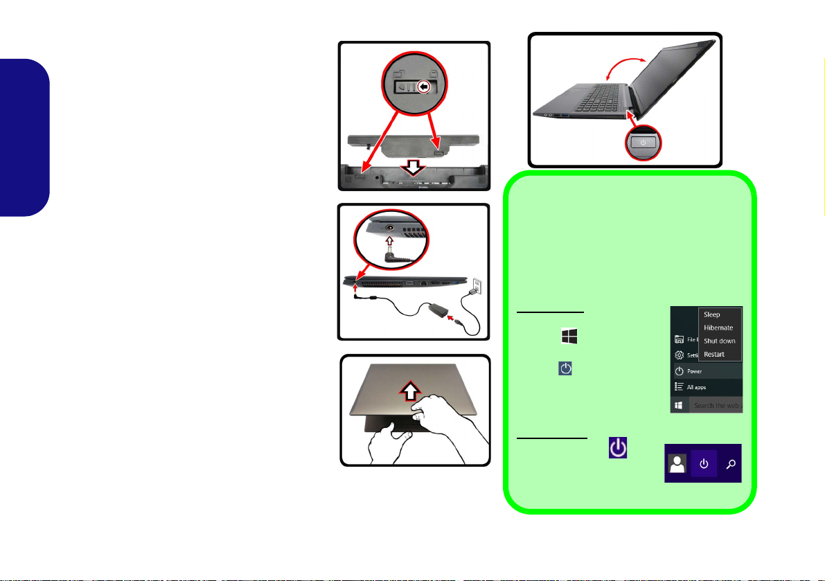
System Startup
130°
Shut Down
Note that you should always shut your computer down by choosing the Shut down
command in Windows (see below). This will
help prevent hard disk or system problems.
Windows 10
1. Click the Start Menu
icon
.
2. Click the Power
item .
3. Choose Shut Down
from the menu.
Windows 8.1
1. Click the icon in
the Start Screen and
choose Shut down
from the menu.
1. Remove all packing materials.
2. Place the computer on a stable surface.
3. Insert the battery and make sure it is locked in
position.
4. Securely attach any peripherals you want to use
with the computer (e.g. keyboard and mouse) to
their ports.
5. Attach the AC/DC adapter to the DC-In jack on
English
the left of the computer, then plug the AC power
cord into an outlet, and connect the AC power
cord to the AC/DC adapter.
6. Use one hand to raise the
comfortable viewing an gle
;
degrees)
Figure 1) to support the base of the computer
(Note: Never lift the computer by the lid/LCD).
7. Press the power button to turn the computer
“on”.
use the other hand (as illustrated in
System Software
Your computer may already come with system software pre-installed. Where this is not
the case, or where you are re-configuring
your computer for a different system, you will
find this manual refers to Microsoft Windows
8.1 and Windows 10.
lid/LCD to a
(do not exceed 130
4
Figure 1 - Opening the Lid/LCD/Computer with AC/DC Adapter Plugged-In
Page 6

Model Differences
This notebook series includes two different model types that mainly differ as indicated in the table below. Note that
your model may appear slightly different from those pictured in this manual.
Model A Model B
Feature
Design I Design II Design III Design I Design II Design III
English
Video
Adapter
Display
Sound
Blaster
Cinema 2
3G/4G
Module
AC
Adapter
Intel® Integrated
GPU (Intel® HD
Graphics 4600) and
NVIDIA® Discrete
GPU (NVIDIA®
GeForce
DC Output 19V,
4.74A
(90W)
940M
)
Intel® Integrated
GPU (Intel® HD
Graphics 4600) and
NVIDIA® Discrete
GPU (NVIDIA®
GeForce GTX
15.6" (39.62cm) HD/FHD 17.3" (43.94cm) HD+/FHD
Yes No Yes No
Option No
DC Output 19.5V,
6.15A (120W)
950M
Intel® Inte-
grated GPU
(Intel® HD
Graphics 4600)
)
DC Output 19V ,
4.74A
(90W)
Intel® Integrated
GPU (Intel® HD
Graphics 4600)
and NVIDIA® Dis-
crete GPU
(NVIDIA®
GeForce
DC Output 19V,
940M
4.74A
(90W)
Intel® Integrated
GPU (Intel® HD
Graphics 4600)
and NVIDIA® Dis-
crete GPU
(NVIDIA®
GeForce GTX
)
950M
DC Output 19.5V ,
6.15A (120W)
Intel® Inte-
grated GPU
(Intel® HD
Graphics
)
DC Output
19V, 4.74A
Table 1 - Model Differences
4600)
(90W)
5
Page 7
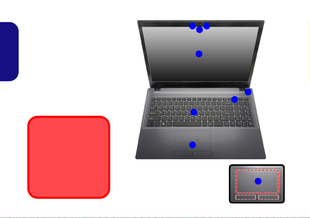
System Map: Front View with LCD Panel Open (Model A)
Note that the Touchpad and
Buttons valid operational area
is that indicated within the red
dotted lines.
Figure 2
Front View with LCD Panel Open
(Model A)
1. PC Camera
2. Built-In Microphone
3. *PC Camera LED
*When the PC camera is in use,
the LED will be illuminated in red.
4. LCD
5. Power Button
6. LED Indicators
7. Keyboard
8. Touchpad & Buttons
5
7
6
2
1
3
4
Wireless Device
Operation Aboard Aircraft
The use of any portable electronic
transmission devices aboard aircraft
is usually prohibited.
Make sure the WLAN, Bluetooth &
3G/4G module(s) are OFF if you are
using the computer aboard aircraft
by putting the system in to Airplane
Mode.
8
8
English
6
Page 8
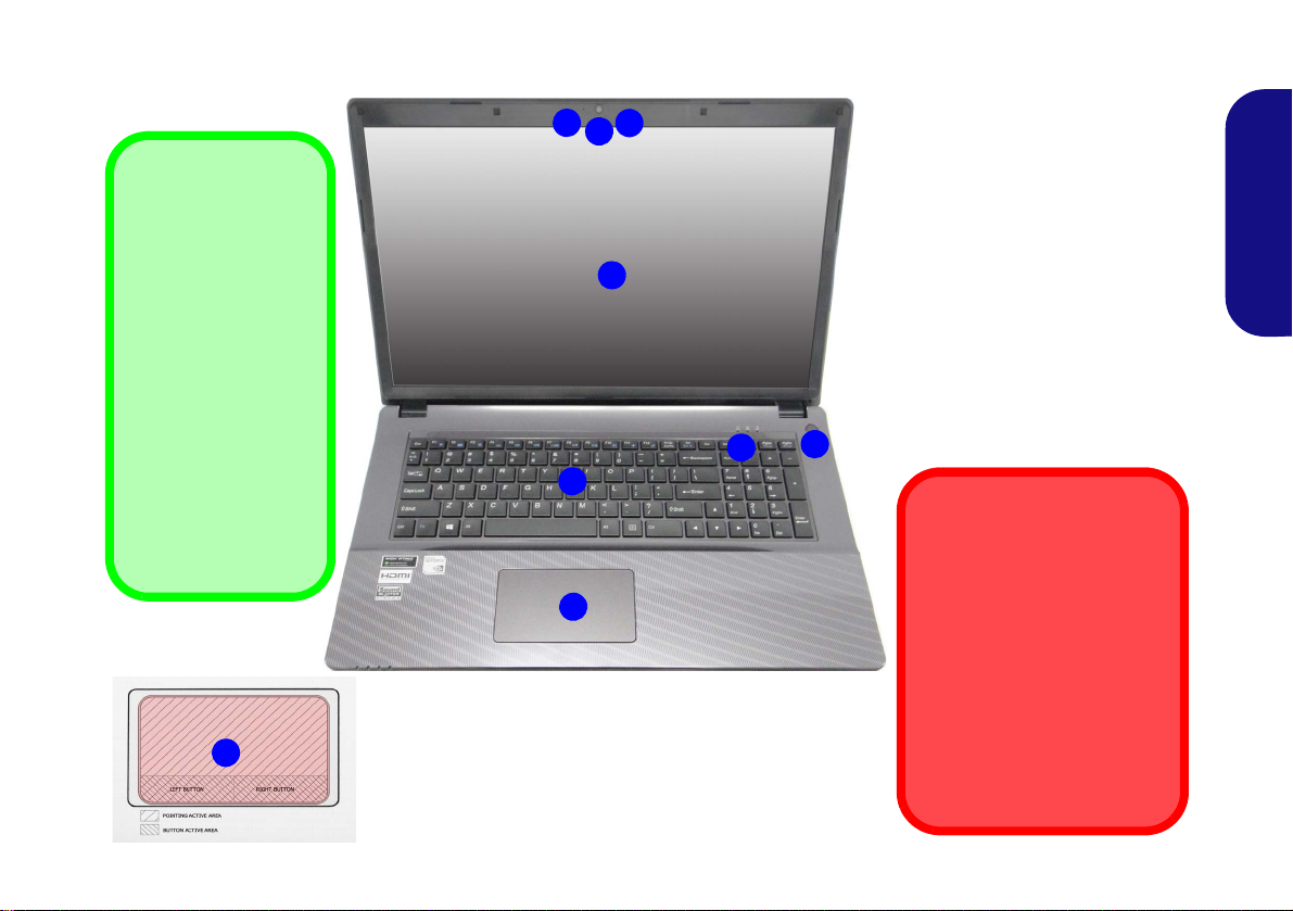
System Map: Front View with LCD Panel Open (Model B)
Figure 3
Front View with LCD Panel
Open (Model B)
1. PC Camera
2. Built-In Microphone
3. *PC Camera LED
*When the PC camera is in
use, the LED will be
illuminated in red.
4. LCD
5. Power Button
6. LED Indicators
7. Keyboard
8. Clickpad/Touchpad
5
7
6
2
1
3
4
Wireless Device
Operation Aboard Aircraft
The use of any portable electronic transmission devices
aboard aircraft is usually prohibited.
Make sure the WLAN & Bluetooth module(s) are OFF if
you are using the computer
aboard aircraft by putting the
system in to Airplane Mode.
8
Clickpad/Touchpad
Sensitivity
The mouse button
zones at the bottom of
the pad measure
about 15mm from the
bottom of the pad,
and the left and right
buttons are divided
roughly down the middle as illustrated below. Press the left
button zone for a left
click, and right button
zone for a right click
action.
8
English
7
Page 9
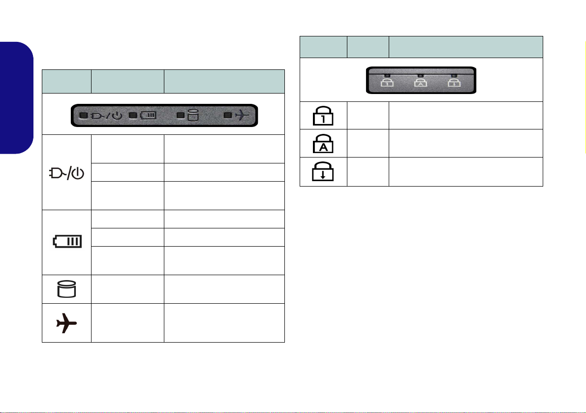
LED Indicators
The LED indicators on the computer display helpful information about the current status of the computer.
Icon Color Description
Icon Color Description
English
8
Orange
Green The Computer is On
Blinking Green
Orange The Battery is Charging
Green The Battery is Fully Charged
Blinking Orange
Green
Green
Table 2 - LED Power Indicators
The AC/DC Adapter is
Plugged In
The Computer is in Sleep
The Battery Has Reached
Critically Low Power Status
The Hard Disk/Optical
Device is in use
Airplane Mode is ON (the
WLAN, Bluetooth & 3G/4G
Modules are OFF)
Mode
Blue
Blue
Blue
Table 3 - LED Status Indicators
Number Lock (Numeric Keypad) Acti-
vated
Caps Lock Activated
Scroll Lock Activated
Page 10
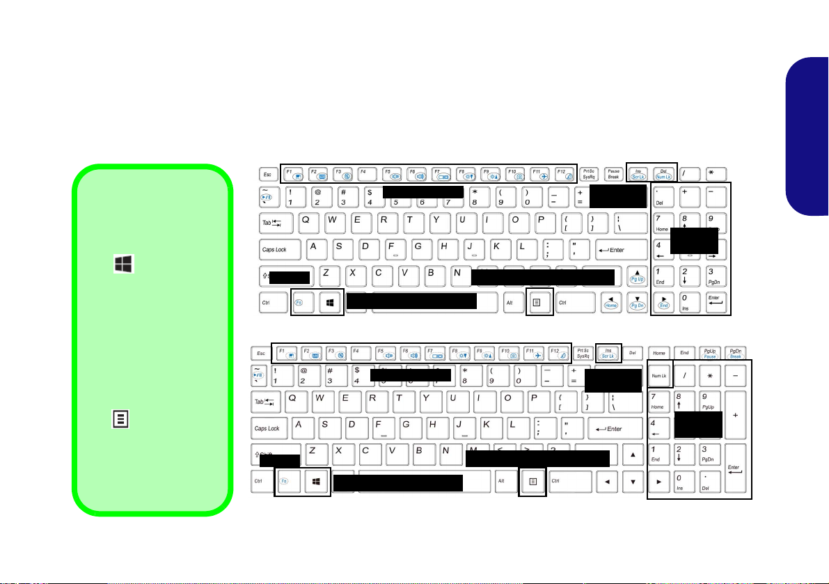
Keyboard
ad
Function Keys
Num Lk &
Scr Lk
Numeric
Keypad
Fn Key
Windows Logo Key
Windows Logo
Keyboard Shortcut
Use the Windows Logo
Key + D key combi-
nation to switch from the
Start screen to the Windows Desktop.
Menu/Application
Keyboard Shortcut
When the Desktop app
is running you can use
the Menu/Application
key on the keyboard
to act as a mouse rightclick. In the Start screen
this function is useful to
quickly display the Cus-
tomize bar.
Menu/Application Key
Function Keys
Num Lk &
Scr Lk
Numeric
Keypad
Fn Key
Windows Logo Key
Menu/Application Key
Model A - Designs I & II
Model B - Designs I & II
The keyboard has a numeric keypad for easy numeric data input. Pressing Fn + Num Lk turns on/off the numeric keypad. It also features function keys to allow you to change operational features instantly.
Models A & B - Designs I & II
(Illuminated keyboards Only) The keyboard illumination level may be adjusted, or turned off/on, by using the Fn +
F4 keys.
English
Figure 4 - Keyboard (Models A & B - Designs I & II)
9
Page 11
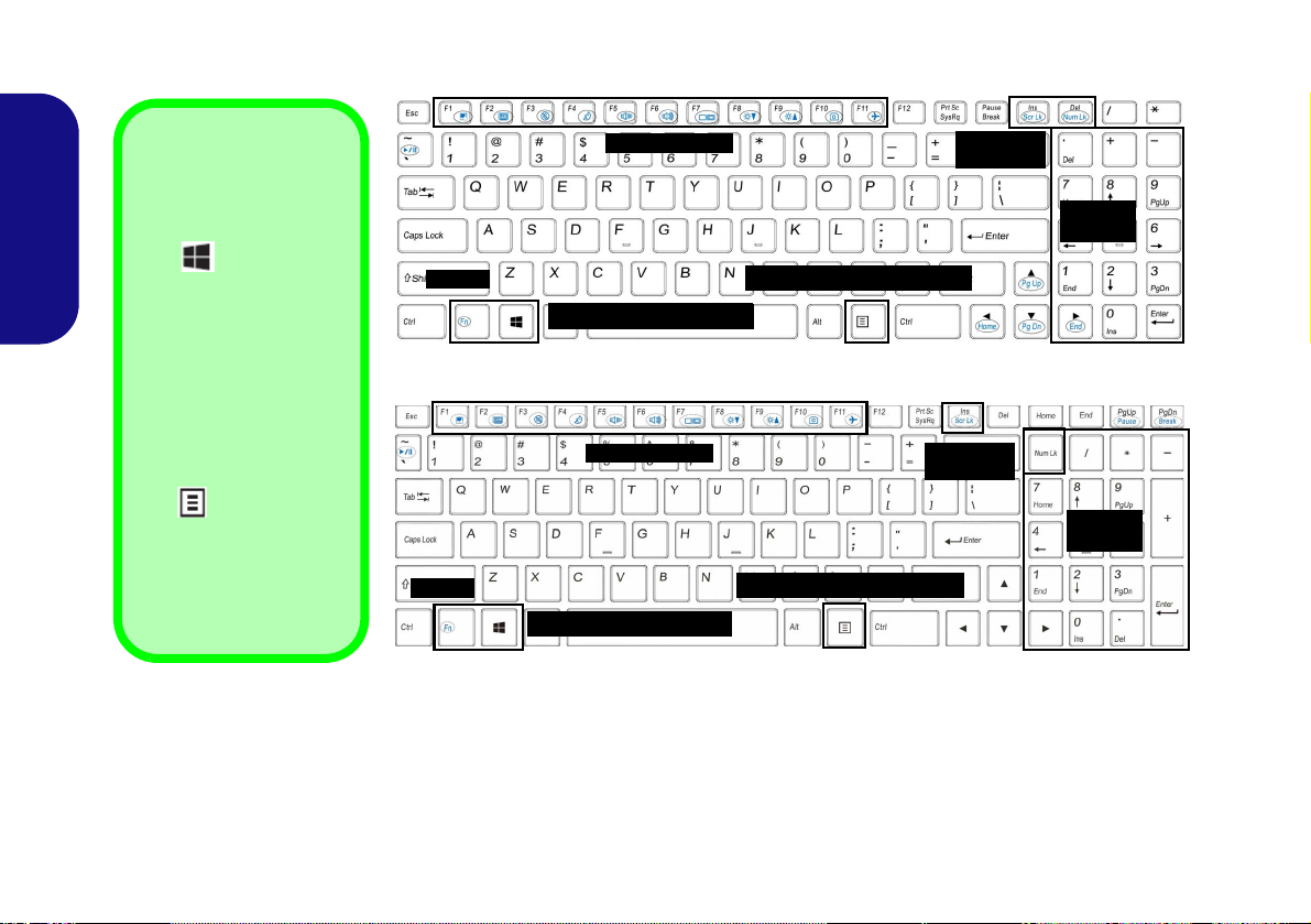
Models A & B - Design III
ad
Function Keys
Num Lk &
Scr Lk
Numeric
Keypad
Fn Key
Windows Logo Key
Windows Logo
Keyboard Shortcut
Use the Windows Logo
Key + D key combi-
nation to switch from the
Start screen to the Windows Desktop.
Menu/Application
Keyboard Shortcut
When the Desktop app
is running you can use
the Menu/Application
key on the keyboard
to act as a mouse rightclick. In the Start screen
this function is useful to
quickly display the Cus-
tomize bar.
Menu/Application Key
Function Keys
Num Lk &
Scr Lk
Numeric
Keypad
Fn Key
Windows Logo Key
Menu/Application Key
Model A - Design III
Model B - Design III
Figure 5 - Keyboard (Models A & B - Design III)
English
10
Page 12

Function Keys & Visual Indicators
Models A & B - Designs I & II
The function keys (F1 - F12 etc.) will act as hot keys when pressed while the Fn key is held down. In addition to the
basic function key combinations, some visual indicators are available when the hot key driver/Control Center driver is
installed (after restart a control panel will pop-up to allow you to select the type of keyboard for your system).
Keys Function/Visual Indicators Keys Function/Visual Indicators
English
Fn +
Fn + Touchpad Toggle Fn + Sleep Toggle
Fn +
Fn + Mute Toggle
Fn +
Fn +
Fn + Change Display Configuration (see page 25)Fn +
Fn +
Fn +
Play/Pause (in Audio/Video Programs)
Turn LCD Backlight Off
(Press a key to or use Touchpad to turn on)
Toggle Keyboard Illumi-
nation/Adjust Brightness
l (Illuminated key-
Leve
boards only)
Volume Decrease/
Increase
Brightness Decrease/
Increase
PC Camera Power
Toggle
Fn +
Fn + /
Fn +
Fn +
Fn +
Table 4 - Function Keys & Visual Indicators (Models A & B
Airplane Mode Tog-
gle
Number Lock Toggle
Scroll Lock Toggle
Caps Lock Toggle
Control Center Toggle (see page 12)
Fan Automatic Con-
trol/ Full Power
Disable/Enable
Flexikey® (see page
15)
- Designs I & II)
11
Page 13

Models A & B - Design III
The function keys (F1 - F11 etc.) will act as hot keys when pressed while the Fn key is held down. In addition to the
basic function key combinations, some visual indicators are available when the hot key driver/Control Center driver is
installed (after restart a control panel will pop-up to allow you to select the type of keyboard for your system).
Keys Function/Visual Indicators Keys Function/Visual Indicators
Fn +
Play/Pause (in Audio/Video Programs)
English
Fn + Touchpad Toggle Fn +
Fn +
Fn + Mute Toggle
Fn + Sleep Toggle
Fn +
Fn + Change Display Configuration (see page 25)Fn +
Fn +
(Press a key to or use Touchpad to turn on)
Volume Decrease/
Brightness Decrease/
Turn LCD Backlight Off
Increase
Increase
Table 5 - Function Keys & Visual Indicators (Models A & B - Design III)
Fn +
Fn + /
Fn +
Fn +
Fn +
PC Camera Power
Toggle
Airplane Mode Tog-
gle
Number Lock Toggle
Scroll Lock Toggle
Caps Lock Toggle
Control Center Toggle (see page 12)
Fan Automatic Con-
trol/ Full Power
Disable/Enable
Flexikey® (see page
15)
12
Page 14

Control Center
Figure 6 - Control Center
Press the Fn + Esc key combination,
or double-click the icon in the no-
tification area of the taskbar to toggle the Control Center on/off. The
Control Center gives quick access to
frequently used controls and enables
you to quickly turn the camera/Touchpad on/off.
Power Modes
You can set a Power Mode by clicking the appropriate icon at the top of
the Control Center. Each power
mode will affect the Power Conservation Mode, Airplane Mode, Power
Plan and PC camera power etc.
Control Center Menus
The Control Center contains 3 menu
headings (System Program, Device
and Gaming) under the Power Modes.
Click the Control Center icons to
toggle the appropriate function, or
hold the mouse button down and move
the dial control where applicable. Certain functions will automatically be
adjusted when a power mode is selected. Click the menu headings and then
click any of the buttons.
Power Status
The Power Status icon will show
whether you are currently powered by
the battery, or by the AC/DC adapter
plugged in to a working power outlet.
The power status bar will show the
current battery charge state.
Brightness
The Brightness icon will show the
current screen brightness level. You
can use the slider to adjust the screen
brightness or the Fn + F8/F9 key combinations, or use the Fn + F2 key combination to turn off the LED backlight
(press any key to turn it on again).
Note that screen brightness is also effected by the Power Mode selected.
Volume
The Volume icon will show the current volume level. You can use the
slider to adjust the volume or the Fn +
F5/F6 key combinations, or use the
Fn + F3 key combination to mute the
volume.
English
13
Page 15

Power Conservation
This system supports Energy Star
power management features that place
computers (CPU, hard drive, etc.) into
a low-power sleep mode after a designated period of inactivity. Click either
the Performance, Balanced or Ener-
gy Star button.
English
Fan Speed
The fan speed will adjust itself automatically to control the heat of the
CPU. However you can adjust the setting to maximum if you prefer. Select
Custom and click on the sliders to adjust the settings to your preference,
however these settings can be overidden by the system, as a safety precaution, if it requires heavier use of the fan.
Sleep Button
Click either the Hibernate or Sleep
button to have the computer enter the
selected power-saving mode.
Display Switch
Click the Display Switch button to access the menu (or use the + P key
combination) and select the appropriate display mode.
Time Zone
Clicking the Time Zone button will
access the Date and Time Windows
control panel.
Desktop Background
Clicking the Desktop Background
button will allow you to change the
desktop background picture.
Touchpad/PC Camera
Click either of these buttons to toggle
the Touchpad or camera module’s
power status. Note that the power status of the camera module is also effected by the Power Mode selected.
Left Windows Key
Click Disable to disable the Windows
Key on the left side of the keyboard.
This may be useful if you are using the
gaming keys (W, A, S & D) and wish
to avoid accidentally triggering menus
with the Windows Key.
Click the numbers under
the Backlight Key
board icon
14
Flexikey®
Page 16

Flexikey® Application
Enabling or Disabling the Flexikey® Profile in Use
You can enable or disable any keyboard or mouse profile
functions currently in use by using the Fn + key
combination. Pressing this key combination will toggle you
between the currently selected keyboard or mouse profile
to the standard keyboard and/or mouse settings, and back
again.
Windows Logo Key and P key
Note that you can assign actions to any keyboard key except the Windows Logo Key and P key.
Figure 7
Flexikey®
Applica-
tion
The Flexikey® application is a quick hotkey configura-
tion application, which allows you to assign a single key
to launch multiple key combinations, or to launch pro-
grams and applications, to create text macros and to
disable certain keys. The application can also be used to
configure the mouse buttons to create hotkeys for gam-
ing etc. All the configuration settings are retained under
(up to12) profiles to which the settings are applied.
The Flexikey® application can be accessed by clicking
the button
ter or by clicking the icon
the desktop taskbar.
in the Gaming section of the Control Cen-
in the notification area of
Profiles
The menus on the left side of the application relate to Profiles. You can Add or Delete profiles (you can maintain
12 active Profiles), Export and Import profiles from the
menus. If you double-click on a profile you can change the
Profile Name, and change an Image file (images created
using PNG files).
English
Keyboard and Mouse Settings
Click Enable to create settings for the keyboard and/or
mouse by clicking the button on the top left of the screen
(e.g. you may wish to create a profile with settings only
for the mouse or keyboard). Clicking on the keyboard or
mouse icons will allow you to access the settings page for
either the keyboard or mouse.
Figure 8 - Enable (Keyboard & Mouse)
15
Page 17

Keyboard Settings
123
4
5
The keyboard settings allow you to configure actions for
any single key (or a combination of keys). Click the key
and then select the Action Type (Express Key, Launch
App, Express Text or Disable) from the menu at the bottom of the page. You can rename the action by clicking in
the Name box, and click in Tool Tips to type in a note to
remind you of the action’s function.
English
Figure 9 - Keyboard Configuration
Mouse Settings
The mouse settings allow you to configure actions for the
left , right and middle buttons of any attached
mouse, and also for any backward and forward
buttons if applicable (on a gaming type mouse). Click the
button number and then select the Action Type (Express
Key, Launch App, Express Text or Disable) from the
menu at the bottom of the page. You can rename the action
by clicking in the Name box, and click in Tool Tips to
type in a note to remind you of the action’s function.
Figure 10 - Mouse Configuration
Flexikey® Application Features:
• EXPRESS KEY - This feature allows you to configure a
single key (or mouse click) to send multiple key combinations, or to create more useful shortcut keys This is useful
in gaming or when using applications which have a complex set of keyboard shortcuts.
• LAUNCH APP - This simply assigns single keys (or
mouse clicks) to launch any program’s or application’s
executable file.
• EXPRESS TEXT - With this you can assign single keys
(or mouse clicks) to send commonly used strings of text.
• DISABLE - Use this function to disable any keyboard
keys or mouse buttons.
• STATISTICS - Use this to quickly record keys in use in
any application, and to disable unused keys.
16
Page 18

Keyboard Settings - Express Key
To configure a single key to send multiple key combinations, or to create more useful shortcut keys, use Express
Key.
1. Enable and select the keyboard under your chosen profile,
click on a key to select it, and then click to select Express Key
in Action Type.
2. In the following example we want to change an existing game
key configuration which uses the left shift key for sprinting, and
the W key for moving forwards, to use the left Ctrl key to
combine this movement to sprint forward.
3. Click on the chosen key for the shortcut action.
4. Click in the Too l Tips field and type to give the key combination
a name e.g. “Sprint Fwds”, then click back in the Name field (to
avoid adding the recorded keys to the Tool Tips name).
5. Click Start Record and then press the key or keys (in this case
we will press Left Shift and W) required (make sure you press
the key(s) required and do not click on them).
6. Click Stop Record to complete the process.
Figure 11 - Keyboard - Express Key
7. Click Save to save the settings within your chosen profile.
8. If you want to remove any individual key click to select it, and
then click Delete.
9. If you want to clear all the settings click Restore to return to the
default key setting.
10. Any assigned Express Keys will appear in orange.
Keyboard Settings - Launch App
You can configure keys to launch any application or program as follows:
1. Enable and select the keyboard under your chosen profile,
click to select a key to launch the appllication, and then click to
select Launch App in Action Type.
2. Click Browse... at the bottom right of the application window.
Figure 12 - Keyboard - Launch App
3. Navigate to the executable file of the application and click
Open.
4. The key will now be configured to open the selected application
under your chosen Profile, and the key will appear in green.
5. If you want to remove any Launch App key, select it and click
on Restore.
6. Click Save to save the settings within your chosen profile.
English
17
Page 19

Power Conservation
This system supports Energy Star
power management features that place
computers (CPU, hard drive, etc.) into
a low-power sleep mode after a designated period of inactivity. Click either
the Performance, Balanced or Ener-
gy Star button.
English
Fan Speed
The fan speed will adjust itself automatically to control the heat of the
CPU. However you can adjust the setting to maximum if you prefer. Select
Custom and click on the sliders to adjust the settings to your preference,
however these settings can be overidden by the system, as a safety precaution, if it requires heavier use of the fan.
Sleep Button
Click either the Hibernate or Sleep
button to have the computer enter the
selected power-saving mode.
Display Switch
Click the Display Switch button to access the menu (or use the + P key
combination) and select the appropriate display mode.
Time Zone
Clicking the Time Zone button will
access the Date and Time Windows
control panel.
Desktop Background
Clicking the Desktop Background
button will allow you to change the
desktop background picture.
Touchpad/PC Camera
Click either of these buttons to toggle
the Touchpad or camera module’s
power status. Note that the power status of the camera module is also effected by the Power Mode selected.
Left Windows Key
Click Disable to disable the Windows
Key on the left side of the keyboard.
This may be useful if you are using the
gaming keys (W, A, S & D) and wish
to avoid accidentally triggering menus
with the Windows Key.
B
F Flexikey®
Click the button to access
the Flexikey® application.
14
Page 20

System Map: Front, Left, Right, Rear & Bottom Views
1
Front
14
Bottom
16
Figure 14 - Front, Left, Right, Rear & Bottom Views
(Model A)
1. LED Indicators
2. Multi-in-1 Card Reader
3. DC-In Jack
4. Vent
5. External Monitor Port
6. RJ-45 LAN Jack
7. Combined eSATA/USB
3.0 Port
8. HDMI-Out Port
9. USB 3.0 Ports
10. Microphone-In Jack
11. Headphone-Out Jack
12. USB 2.0 Port
13. Optical Device Drive
Bay
14. Emergency Eject Hole
15. Security Lock Slot
16. Battery
17. Component Bay Cover
18. Speakers
2
8
4
6
3
Left
Right
5
Rear
10
12
9
7
13
15
17
18
18
2
Overheating
To prevent your computer from overheating
make sure nothing blocks any vent while the
computer is in use.
Disc Emergency Eject
If you need to manually eject a disc (e.g. due
to an unexpected power interruption) you
may push the end of a straightened paper
clip into the emergency eject hole. Do not
use a sharpened pencil or similar object that
may break and become lodged in the hole.
USB 3.0 Port
USB 3.0 will
transfer data
much faster than
USB 2.0, and is
backwards-compatible with USB
2.0.
16
11
4
4
9
(Model A)
English
19
Page 21

System Map: Front, Left, Right, Rear & Bottom Views
1
Front
14
Bottom
16
Figure 15 - Front, Left, Right, Rear & Bottom Views
(Model B)
1. LED Indicators
2. Multi-in-1 Card Reader
3. DC-In Jack
4. Vent
5. External Monitor Port
6. RJ-45 LAN Jack
7. Combined eSATA/USB
3.0 Port
8. HDMI-Out Port
9. USB 3.0 Ports
10. Microphone-In Jack
11. Headphone-Out Jack
12. USB 2.0 Port
13. Optical Device Drive Bay
14. Emergency Eject Hole
15. Security Lock Slot
16. Battery
17. Component Bay Cover
18. Speakers
2
8
4
6
3
Left
Right
5
Rear
10
12
9
7
13
15
17
4
18
18
Overheating
To prevent your computer from overheating
make sure nothing blocks any vent while the
computer is in use.
Disc Emergency Eject
If you need to manually eject a disc (e.g. due
to an unexpected power interruption) you
may push the end of a straightened paper
clip into the emergency eject hole. Do not
use a sharpened pencil or similar object that
may break and become lodged in the hole.
USB 3.0 Port
USB 3.0 will
transfer data
much faster than
USB 2.0, and is
backwards-compatible with USB
2.0.
16
11
9
4
4
4
(Model B)
English
20
Page 22

Windows 10 Start Menu, Context Menu, Taskbar, Control Panel and Settings
Most of the apps, control panels, utilities and programs within Windows 10 can be
accessed from the Start Menu by clicking the icon in the taskbar in the lower
left corner of the screen (or by pressing the Windows Logo Key on the keyboard).
Right-click the Start Menu icon (or use the Windows Logo Key + X key
combination) to bring up an advanced Context Menu of useful features such as
Control Panel, Programs and Features, Power Options, Task Manager, Search, File
Explorer, Command Prompt, Device Manager and Network Connections etc.
The notification area of the taskbar is in the bottom right of the screen. Some of the
Control Panels and applications referred to throughout the course of this manual
can be accessed from here.
Throughout this manual you will see an instruction to open the Control Panel. To
access the Control Panel, right-click the Start Menu icon
lower left corner of the screen and select Control Panel from the menu. Or, press
the Windows logo key on your keyboard and X to bring up the context menu,
and then press P to bring up the Control Panel.
The Settings item in the Start Menu (and also as an App) gives you quick access
to a number of system settings control panels allowing you to adjust settings for
System, Devices, Network & internet, Personalization, Accounts, Time & language, Ease of Access, Privacy and Update & security.
in the taskbar in the
English
Figure 16 - Start Menu, Context Menu, Taskbar, Control Panel and Settings
21
Page 23

Windows 8.1 Start Screen,
Figure 17 - Start Screen (Windows 8.1)
Figure 18 - Start Screen with Charms Bar (Win-
dows 8.1)
Desktop and Charms Bar
The Apps, control panels, utilities and programs within
Windows 8.1 are accessed from the Start screen and/or
Windows Desktop app. The Desktop (which runs as an
app within the Start screen) can be accessed by clicking
the Desktop item in the Start screen (or by using the Win-
English
dows Logo Key + D key combination). The taskbar is
displayed at the bottom of the desktop screen, and you can
see the notification area of the taskbar in the bottom right
of the screen. Click the arrow at the bottom of the Start
screen to access Apps.
The right side of the screen displays the Charms Bar. The
Charms Bar contains the Search, Share, Start, Devices
and Settings menus. To access up the Charms Bar move
the cursor to the upper or lower right corners of the screen,
and then hover over one of the items in the Charms Bar to
activate it (the bar will be black when it is active), or use
the Windows Logo Key + C key combination.
22
Page 24

Windows 8.1 Control Panel
Move the mouse to the bottom left of the
screen and right-click the Start button to
access the menu.
Figure 19 - Context Menu (Windows 8.1)
Throughout this manual you will see an instruction to
open the Control Panel. Right-click the Start button
in the Desktop app or Start screen (or use the Windows
Logo Key + X key combination) to bring up an advanced context menu of useful features such as Control
Panel, Programs and Features, Power Options, Task Manager, Search, File Explorer, Command Prompt, Device
Manager and Network Connections etc. and then select
Control Panel.
English
23
Page 25

Video Features
Designs I & II feature both an Intel’s Integrated GPU
(for power-saving) and an NVIDIA’s discrete GPU (for
performance). Design III features an Intel’s Integrated
GPU. You can switch display devices, and configure display options as long as the appropriate video driver is installed.
English
Microsoft Hybrid Graphics
(Designs I & II Only)
Microsoft Hybrid Graphics is a seamless technology
designed to get best performance from the graphics system while allowing longer battery life, without having to
manually change settings. The computer will automatically and seemlessly switch between the integrated UMA
(Unified Memory Architecture) GPU (iGPU) and the discrete GPU (dGPU) when required by the applications in
use.
To access the Display control panel in Windows:
1. Go to the Control Panel.
2. Click Display (icon) - in the Appearances and
Personalization category.
3. Make the required changes from the Display, Resolution,
Orientation or Multiple display menus.
4. Click Apply to save the settings.
To access the Intel® HD Graphics Control Panel:
1. (Windows 8.1 Only) Click the icon (Intel® HD Graphics Control Panel) on the Apps screen.
OR
2. Right-click the desktop and select Graphics Properties from
the menu.
OR
3. Click the icon in the notification area of the Desktop taskbar
and select Graphics Properties from the menu.
4.
To access the NVIDIA Control Panel:
(Designs I & II Only)
1. Go to the Control Panel.
2. Click NVIDIA Control Panel (icon) - in the Appearances and
Personalization category.
OR
3. Right-click the desktop and select NVIDIA Control Panel from
the menu.
24
Page 26

Display Devices & Options
Figure 20
Project
Figure 21 - Power Options
Besides the built-in LCD you can also use an external
monitor/flat panel display/TV (TV through HDMI-Out
port only), connected to the external monitor port or to the
HDMI-Out port (High-Definition Multimedia Interface)
as your display device.
In Windows it is possible to quickly configure external
displays from the Project menu (press the Windows Logo
Key and the P key).
To configure the displays using the Project menu:
1. Attach your external display device to the appropriate port, and
then turn it on.
2. Press the + P (or Fn + F7) key combination.
3. Click on any one of the options from the menu to select PC
screen only, Duplicate, Extend or Second screen only.
Power Options
The Power Options (Hardware and Sound menu) control panel icon in Windows allows you to configure power
management features for your computer. You can conserve power by means of power plans and configure the
options for the power button, sleep button (Fn + F12),
computer lid (when closed), display and sleep mode (the
default power saving state) from the left menu. Note that
the Power saver plan may have an affect on computer
performance.
Click to select one of the existing plans, or click Create a
power plan in the left menu and select the options to create a new plan. Click Change Plan Settings and click
Change advanced power settings to access further configuration options.
English
25
Page 27

Audio Features
Volume Adjustment
The sound volume level can also be set using the volume control within Windows. Click the Speaker icon in
the taskbar to check the setting
.
Sound Blaster
Cinema 2 & HDMI
Note that the Sound
Blaster Cinema 2 audio effects do not apply to audio generated
through an HDMI connection.
You can configure the audio options on your computer
from the Sound control panel in Windows, from the
HD VDeck icon on the desktop or VIA HD Audio Deck
control panel.
The volume may be adjusted by means of the Fn + F5/F6
key combination or the volume icon in the taskbar.
English
Sound Blaster Cinema 2
Install the Sound Blaster Cinema application to allow
you to configure the audio settings to your requirements
for the best performance in games, music and movies.
Sound Blaster Cinema 2 Application
Run the Sound Blaster Cinema control panel from the
notification area of the taskbar (or from the item in the
Apps screen). Click on the tabs to access any of the control panel menus.
26
Figure 22 - Sound Blaster Cinema 2
(Taskbar Notification Area Icon)
Page 28

Driver Installation
Driver Installation General
Guidelines
As a general guide follow the
default on-screen instructions for each driver (e.g.
Next > Next > Finish) unless
you are an advanced user. In
many cases a restart is required to install the driver.
Make sure any modules (e.g.
WLAN or Bluetooth) are ON
before installing the appropriate driver.
Windows Update
After installing all the drivers
make sure you enable Win-
dows Update in order to get
all the latest security updates
etc. (all updates will include
the latest hotfixes from Mi-
crosoft).
Driver Installation & Power
When installing drivers make sure
your computer is powered by the AC/
DC adapter connected to a working
power source. Some drivers draw a
significant amount of power during the
installation procedure, and if the remaining battery capacity is not adequate this may cause the system to
shut down and cause system problems (note that there is no safety issue involved here, and the battery will
be rechargeable within 1 minute).
Figure 23 - Install Drivers
The Device Drivers & Utilities + User’s Manual disc contains the drivers and utilities
necessary for the proper operation of the computer. This setup will probably have already been done for you. If this is not the case, insert the disc and click Install Drivers
(button), or Option Drivers (button) to access the Optional driver menu. Install the
drivers in the order indicated in Figure 23. Click to select the drivers you wish to
install (you should note down the drivers as you install them). Note: If you need to
reinstall any driver, you should uninstall the driver first
Manual Driver Installation
Click the Browse CD/DVD button in the Drivers Installer application and browse to
the executable file in the appropriate driver folder.
If a
Found New Hardware
Cancel, and follow the installation procedure as directed.
wizard appears
during the installation procedure, click
.
English
27
Page 29

TPM (Option)
Figure 24 - BitLocker Drive Encryption
(TPM Administration)
Figure 25
Trusted Platform Module
(TPM) Manage-
ment on Local
Computer Ad-
ministration
Figure 26
Actions Menu
Before setting up the TPM (Trusted Platform Module)
functions you must initialize the security platform.
Activating TPM
1. Restart the computer .
2. Enter the Aptio Setup Utility pressing <F2> during the POST.
3. Use the arrow keys to select the Security menu.
English
4. Select TPM Configuration and press Enter.
5. Press Enter to access the Security Device Support menu and
select Enable.
6. You will then need to press <F4> to save the changes and
restart the computer.
4. The TPM Management window allows you to configure the
TPM within Windows. As TPM is usually administered within
large enterprises and organizations, your system administrator
will need to assist you in managing the information here.
TPM Management in Windows
You can manage your TPM settings from within Windows:
1. Go to the Control Panel.
Click
2.
3. Click TPM Administration.
28
BitLocker Drive Encryption (System and Security).
TPM Actions
1. Click Prepare the TPM and follow the instructions in the Wizard to prepare the TPM (this will probably require a restart of
the computer and confirmation of the setting changes after
restart by pressing the appropriate F key).
2. After the restart the TPM will be prepared and you can then use
the Actions menu to Turn TPM off, Change Owner
Password, Clear TPM or Reset TPM Lockout.
3. A wizard will help take you through any setup steps.
Page 30

3G/4G Module (Option)
1
Model A
USIM Card
Orientation
Note that the USIM
card’s readable side
(with the gold-colored
contacts) should face
upwards as illustrated.
1
1
(Optional for Model A Only)
If you have included an optional 3G/4G module in your purchase option, follow the instructions below to install the
USIM card (which will be provided by your service provider).
USIM Card Insertion
1. Turn off the computer, and turn it over and remove the battery (slide the latches in the direction indicated below and slide th e battery out).
2. Insert the USIM card as illustrated below until it clicks into position, and replace the battery.
English
Figure 27 - Remove the battery and Insert the USIM Card
29
Page 31

Troubleshooting
Problem Possible Cause - Solution
The Wireless LAN/Bluetooth
modules cannot be detected.
English
The PC Camera module cannot be
detected.
The captured video files from the PC
Camera are taking up too much disk
space.
The modules are off as the computer is in Airplane Mode. Check the LED in dicator
and/or function key indicator to see if it is in Airplane Mode (see Table 2 on page 8). Use
the Fn + F11 key combination to toggle Airplane Mode on/off (see Table 4 on page 11).
The module is off. Press the Fn + F10 key comb inati on in order to enab le th e module (see
Table 4 on page 11). Run the camera application to view the camera picture.
Note that capturing high resolution video files requires a substantial amount of disk space
for each file.
Note that the Windows system requires a minimum of 20GB (64bit) of free space on the
C: drive system partition. It is recommended that you save the capture video file to a
location other than the C:drive, limit the file size of the captured video or reduce video
resolution.
30
Page 32

Specifications
Latest Specification Information
The specifications listed in this here
are correct at the time of going to
press. Certain items (particularly processor types/speeds) may be
changed, delayed or updated due to
the manufacturer's release schedule. Check with your service center
for details.
Processor Options
Intel® Core™ i7 Processor
i7-4910MQ (2.90GHz)
8MB L3 Cache, 22nm, DDR3L-1600MHz,
TDP 47W
i7-4810MQ (2.80GHz), i7-4710MQ
(2.50GHz)
6MB L3 Cache, 22nm, DDR3L-1600MHz,
TDP 47W
i7-4610M (3.00GHz)
4MB L3 Cache, 22nm, DDR3L-1600MHz,
TDP 37W
Intel® Core™ i5 Processor
i5-4340M (2.90GHz), i5-4310M (2.70GHz),
i5-4210M (2.60GHz)
3MB L3 Cache, 22nm, DDR3L-1600MHz,
TDP 37W
Intel® Core™ i3 Processor
i3-4110M (2.60GHz)
3MB L3 Cache, 22nm, DDR3L-1600MHz,
TDP 37W
Pentium® Processor
Intel®
3560M (2.40GHz)
2MB L3 Cache, 22nm, DDR3L-1600MHz,
TDP 37W
Core Logic
Intel® HM86 Chipset
BIOS
48Mb SPI Flash ROM
AMI BIOS
Memory
Two 204 Pin SO-DIMM Sockets Supporting
DDR3L 1600MHz Memory
Memory Expandable up to 16GB
English
(The real memory operating frequency
depends on the FSB of the processor.)
Storage
One Changeable 2.5" 9.5mm/7.0mm (h)
SATA HDD/SSD
(Factory Option) One 12.7mm(h) Optical
Device Type Drive (Super Multi Drive)
(Factory Option) 2.5" 9.5mm 2nd HDD/
SSD caddy
(Factory Option) One mSATA Solid State
Drive (SSD)
LCD Options
Model A :
15.6" (39.62cm) HD / FHD
Model B:
17.3" (43.94cm) HD+ / FHD
31
Page 33

Video Adapter (Design I)
Intel® Integrated GPU and NVIDIA®
Discrete GPU
Supports Microsoft Hybrid Graphics
Intel Integrated GPU
Intel® HD Graphics 4600
Dynamic Frequency (Intel Dynamic Video
English
Memory Technology for up to 1.7GB)
Microsoft DirectX®11.1 Compatible
NVIDIA® Discrete GPU
NVIDIA® GeForce 940M
2GB GDDR3 Video RAM on board
Microsoft DirectX® 12 Compatible
Video Adapter (Design II)
Intel® Integrated GPU and NVIDIA®
Discrete GPU
Supports Microsoft Hybrid Graphics
Intel Integrated GPU
Intel® HD Graphics 4600
Dynamic Frequency (Intel Dynamic Video
Memory Technology for up to 1.7GB)
Microsoft DirectX®11.1 Compatible
NVIDIA® Discrete GPU
NVIDIA® GeForce GTX 950M
2GB GDDR3 Video RAM on board
Microsoft DirectX® 12 Compatible
Video Adapter (Design III)
Intel Integrated GPU
Intel® HD Graphics 4600
Dynamic Frequency (Intel Dynamic Video
Memory Technology for up to 1.7GB)
Microsoft DirectX®11.1 Compatible
Audio
High Definition Audio Compliant Interface
2 * Built-In Speakers
Built-In Microphone
(Designs I & II Only) Sound Blaster™ Cinema 2
Security
Security (Kensington® Type) Lock Slot
BIOS Password
(Factory Option) TPM v 2.0
Keyboard (Designs I & II)
Model A:
Full-size “WinKey” keyboard (with numeric
keypad)
Model B:
Full-size “WinKey” keyboard (with numeric
keypad)
(Factory Option) Illuminated Full-size
“WinKey” keyboard (with numeric keypad)
Keyboard (Design III)
Full-size “WinKey” keyboard (with numeric
keypad)
Pointing Device
Built-in Touchpad
Interface
One USB 2.0 Port
Two USB 3.0 Ports
One eSATA Port (USB 3.0 Combo)
One HDMI-Out Port
One External Monitor Port
One Headphone-Out Jack
One Microphone-In Jack
One RJ-45 LAN Jack
One DC-in Jack
Mini Card Slots
Model A:
Slot 1 for WLAN Module or WLAN and
Bluetooth Combo Module
Slot 2 for mSATA SSD
Or
(Factory Option) Slot 2 for M.2 3G/4G
Module
Model B:
Slot 1 for WLAN Module or WLAN and
Bluetooth Combo Module
Slot 2 for mSATA SSD
32
Page 34

Card Reader
Embedded Multi-In-1 Card Reader
MMC (MultiMedia Card) / RS MMC
SD (Secure Digital) / Mini SD / SDHC/
SDXC
MS (Memory Stick) / MS Pro / MS Duo
Communication
Built-In Gigabit Ethernet LAN
1.0M HD PC Camera Module
(Factory Option) 2.0M FHD PC Camera
Module
(Factory Option - Model A Only) 3G or 4G
M.2 Module
WLAN/ Bluetooth Half Mini-Card
Modules:
(Factory Option) Intel® Wireless-AC 3160
Wireless LAN (802.11ac) + Bluetooth 4.0
(Factory Option) Intel® Wireless-AC 7260
Wireless LAN (802.11ac) + Bluetooth 4.0
(Factory Option) Intel® Wireless-N 7260
Wireless LAN (802.11b/g/n)
(Factory Option) Third-Party Wireless LAN
(802.11b/g/n)
(Factory Option) Third-Party Wireless LAN
(802.11b/g/n) + Bluetooth 4.0
Environmental Spec
Temperature
Operating: 5
Non-Operating: -20°C - 60°C
Relative Humidity
Operating: 20% - 80%
Non-Operating: 10% - 90%
°C - 35°C
Power (Designs I & III)
Full Range AC/DC Adapter
AC Input: 100 - 240V, 50 - 60Hz
DC Output: 19V, 4.74A (90W)
(Factory Option) Removable 6 Cell Smart
Lithium-Ion Battery Pack, 62.16WH
(Factory Option) Removable 6 Cell Smart
Lithium-Ion Battery Pack, 48.84WH
Power (Design II)
Full Range AC/DC Adapter
AC Input: 100 - 240V, 50 - 60Hz
DC Output: 19.5V, 6.15A (120W)
(Factory Option) Removable 6 Cell Smart
Lithium-Ion Battery Pack, 62.16WH
(Factory Option) Removable 6 Cell Smart
Lithium-Ion Battery Pack, 48.84WH
Dimensions & Weight
Model A:
374mm (w) * 252mm (d) * 14 - 31.4mm (h)
OR
374mm (w) * 249.5mm (d) * 14.8 - 32.8mm
(h)
2.5kg (Barebone with ODD and 62.16WH
Battery)
Model B:
413mm (w) * 272.8mm (d) * 36.4mm (h)
3.1kg (Barebone with ODD and 62.16WH
Battery)
English
33
Page 35

English
34
 Loading...