

Page 1

QUICK START GUIDE
SmarterHome™ IP54 Battery
Powered Fingerprint Smart
Wi-Fi Door Lock
(KASHFNGDLKA)
Page 2

CONTENTS
Before starting .......................................02
Installation .............................................. 03
Operation ................................................. 12
Using the app ......................................... 14
Troubleshooting ...................................... 18
Specifications .......................................... 19
2
Page 3

BEFORE STARTING
NOTE
Please have a Phillips-head screwdriver and 4x AA batteries on hand before
commencing installation.
Please read the following before starting:
• It is recommended to have this installed by a professional.
• Please note that the connection line should not be pressed, bent or
folded during installation.
• Before the installation, ensure the lock is suitable for the door, or the
direction of the handle must be adjusted according to the door opening
direction.
• While installing, the door must be in a half-open state until the
installation is complete.
• After the installation is complete, test whether the front handle and
back handle unlock/lock normally.
• If it does not work properly, please check if there has been an error
during installation, and consult the Installation Debugging steps on
page 11. If still experiencing difficulty, head online to Kogan.com’s help
centre at help.kogan.com
3
Page 4

INSTALLATION
Installation overview
1. Front panel
2. Connection
column
3. Square steel
4. Lock body
5. Connection line
6. Back panel
7. SET button
8. Connection
column screws
4
9. Battery cover
10. Battery cover
screw
11. Back handle
12. Connection
column screws
13. Reverse lock knob
14. Back locking
paddle
15. Dead-bolt
16. Latch-bolt
17. Lock body screws
18. Connection
column
19. Keyhole
20. Emergency power
port
21. Front handle
Page 5

1. Confirming door configuration
This smart lock is suitable of 4 kinds of door opening directions. Identify
the correct configuration of your door before commencing installation.
Left-hand door configurations
From the outside, the door
swings inwards to the left.
From the outside, the door
swings outwards to the left.
Right-hand door configurations
From the outside, the door
swings inwards to the right.
From the outside, the door
swings outwards to the right.
TIP
If you get stuck at Step 6.1 setting the dot position, check back here
to ensure you’ve selected the correct door configuration.
5
Page 6

INSTALLATION (cont’d)
2. Open hole
Following the hole installation template, drill the holes in your door to
facilitate installation. If you require another installation template, these
are available as a free download from kogan.com
3. Changing the handle direction
Check if the handle direction is appropriate for the door (facing left or
right). If it is correct, continue on to step 4.
If is not the correct direction, this can be changed via the following:
a. Front handle direction change
Disassemble the direction-changing screw, carefully and slowly twist
the handle clockwise 180°, then re-tighten the direction-changing
screw. Check that the handle is not stuck in place, and can be
turned easily.
b. Rear handle direction change
Disassemble the direction-changing screw, carefully and slowly twist
the handle clockwise 180°, then re-tighten the direction-changing
screw. Check that the handle is not stuck in place, and can be
turned easily.
c. Match the front handle and back handle to make sure they are in
the correct direction.
Page 7
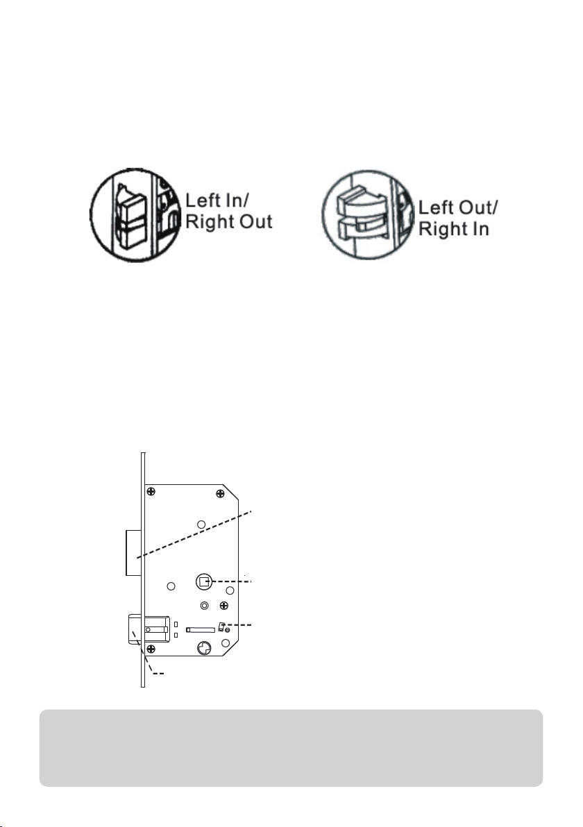
4. Installing lock body
Set the installation direction of the latch-bolt in the lock body according
to the door opening direction. Check back to step 1 if you are unsure.
To change the direction of the lock body:
a. Push the reversing block to the other side.
b. Push the latch-bolt into the lock and turn it 180 degrees.
c. Put back the reversing block and the latch-bolt will pop up
automatically.
Following this, place the lock body into the door frame and tighten with
2 fixing screws.
Lock Body (5052)
Dead-bolt
Square steel hole
Reversing block
Latch-bolt
NOTE
Don’t forcefully unlock by heavily pressing down the lock handles
while reversing lock body set.
7
Page 8
INSTALLATION (cont’d)
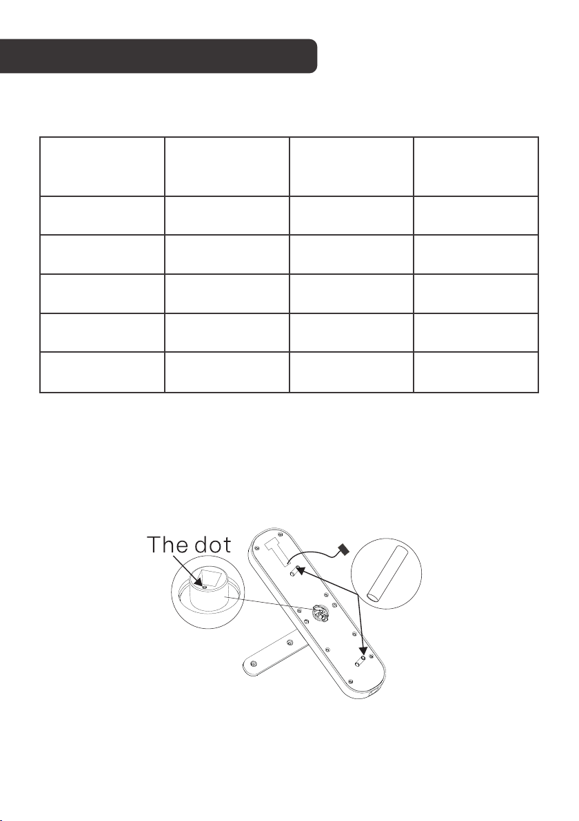
5. Select parts
Choose the suitable parts according to the following table.
Door thickness
40-51 mm 80mm 35mm 30mm+50mm
52-60mm 80mm 35 or 55mm 50mm+70mm
61-80mm 100mm 55mm 50mm+70mm
81-100mm 120mm 55mm 70mm+90mm
1 00mm
(optional)
6. Installing the lock
6.1 Front panel
a. Install 2 connection columns on the front panel.
Square steel
length
140mm 55mm 90mm+110mm
Connection
column length
Connection
column screw
length
8
Page 9
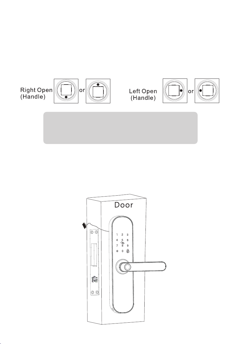
b. Adjust the dot direction on the square steel sleeve with reference to
the sticker on the rubber mat:
• Left-hand door configurations: set the dot left or right
• Right-hand door configurations: set the dot at the top or bottom
TIP
Check back to step 1 to ensure you’ve selected the
correct dot position for your door configuration.
c. Insert the suitable square steel into the lock body.
d. Pass the connection line through the door hole.
e. Align the square steel with the square steel hole of the front panel
and fix the front panel on the door, then press the other end of the
square steel.
9
Page 10
INSTALLATION (cont’d)
6. Installing the lock (continued)
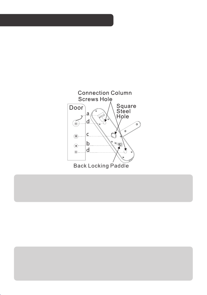
6.2 Rear panel
a. Press the front panel and connect the connection line with the
corresponding interface of the back panel, then insert the excess
line into the door hole.
b. Insert the back-locking paddle into the lock body. You can cut off
one or two sections of the back-locking paddle according to the
thickness of the door.
NOTE
The length of the back-locking paddle should not exceed the
thickness of the door.
c. Align the square steel with the square steel hole of the back panel
and compress the back panel.
d. Lock with 2 connection column screws to fix the back panel.
e. Install 4x AA batteries and the battery cover, then lock the battery
cover with the screw.
NOTE
When installing the back lock, look through the screw hole and make
sure the connection wire is not blocking the connection column hole
to avoid damaging the connection wire when installing the screw.
10
Page 11
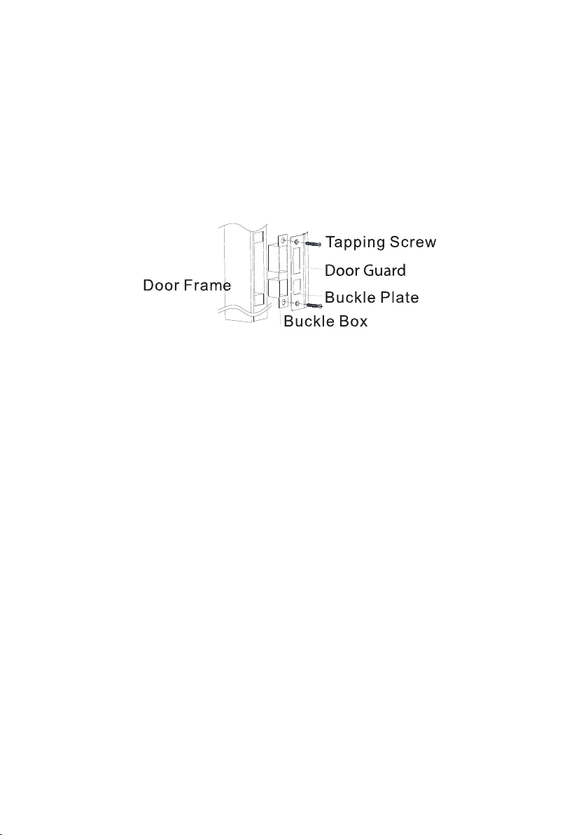
7. Installing buckle plate and buckle box
Following the hole installation template (see Step 2), drill the holes in
your door frame for the buckle box. Position the buckle box first, before
the following with the buckle plate.
Ensure the buckle plate is installed with the door guard facing door’s
swing direction.
8. Installation Debugging
Double check all of the following points before finalising your
installation. This will ensure that installation has been performed
correctly, and that your door lock will perform as intended. Keep the
door in a half-open status while debugging.
a. Check whether the following functions can be achieved or not:
• Press down front handle: latch-bolt/dead-bolt remains locked in locked
status.
• Press down front handle: latch-bolt/dead-bolt retract in unlocked
status.
• Lift up front handle: enable dead-bolt in any status.
• Press down back handle: latch-bolt/dead-bolt retract in any status.
• Lift up back handle: enable dead-bolt in any status.
b. When locking in reverse direction from inside, press down the front
handle/back handle, the latch-bolt/deadbolt should not move.
c. Verify other functions are normal or not, including self-locking,
virtual password, setting button, app remote unlocking etc.
11
Page 12

OPERATION
Deadbolt function
To activate the dead-bolt, lift up on the door handle.
Adding administrators
The first 3 added users will be classified as administrators and cannot
be removed unless lock is reset. is used as the back and sign out
button, while is used as the confirm button.
1. Remove the battery cover, short press Set (back panel) or long
press . The voice will prompt “Please add administrator.”
2. Add the administrator’s fingerprint (3 times to confirm), card, or
password (6-8 numbers, twice to confirm) followed by .
3. The voice will say “added successfully.”
NOTE
Different position fingerprints can be added to improve the
fingerprint identification rate.
Adding users
An administrator is required to verify and assist in adding another user.
1. Remove the battery cover, short press Set (back panel) or long
press . The voice will prompt “Please verify the administrator.”
2. Verify administrator by confirming fingerprint, card, or password.
3. Add the new user’s fingerprint (3 times to confirm), card, or
password (6-8 numbers, twice to confirm) followed by .
4. The voice will say “added successfully.”
Deleting users
1. Remove the battery cover, short press Set (back panel) or long
press . The voice will prompt “Please verify the administrator.”
2. Verify administrator by confirming fingerprint, card, or password.
3. Short press Set or long press again.
4. Press 1 to remove all user fingerprints, 2 to remove all user
passwords, 3 to remove all user cards, or 4 to remove all users.
5. Upon entering a selection, the voice will say “Successful.”
NOTE
The administrator cant be removed by doing this, only normal users.
To remove administrators, factory reset is required.
12
Page 13

Change password
1. Press 7 and , you will hear a long beep from the lock.
2. Enter the old password that is to be changed. The voice will
prompt “Please add user.”
3. Enter the new password, followed by . The voice will then say
“Successful.” The previous password will now be invalid.
Factory reset (Restore to default settings)
1. Remove the battery cover, long press Set for 3 seconds and verify
the administrator.
2. The system will restore itself to factory default settings.
NOTE
Following a factory reset, all user and administrator information is
erased. The password will return to the default 1-2-3-4-5-6-7-8-9-0.
Add a new administrator immediately.
Self-locking
If the password is entered incorrectly 5 times in a row, the system will
be locked for 180 seconds (3 minutes). Using the fingerprint or card will
override the self-lock.
If the fingerprint is entered incorrectly 5 times in a row, the system will
be locked for 180 seconds (3 minutes). Using the card will override the
self-lock.
Low power warning
When the battery power is lower than 4.6v, the lock will enable.
Replace the batteries immediately. Do not mix brands, or new and used
batteries.
Virtual password (anti-peeping protection)
Enter a virtual password before or after the correct password and it can
then be unlocked. Do not exceed 30 digits, and ensure the correct code
is entered in a continuous sequence.
Doorbell function
Press while in standby or initial state to sound the doorbell.
Volume adjustment
Press 3-3-3 followed by to change volume from mute, low, medium
and high.
13
Page 14
USING THE APP
Installing the app
Download the Kogan SmarterHome app from the Play Store (Android)
or App Store (iOS).
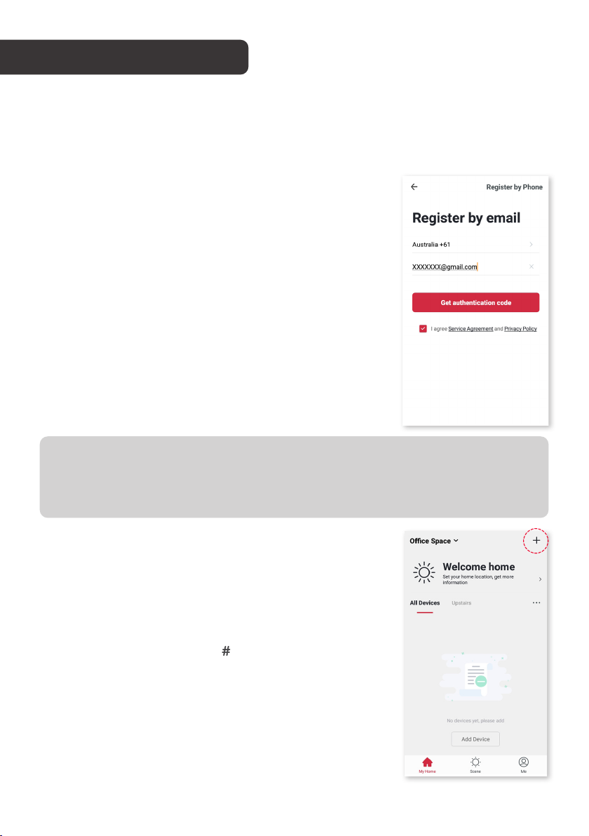
Creating SmarterHome account
If you do not have a Kogan SmarterHome
account, register or sign in with a verification code
sent by SMS.
To register:
1. Tap to enter registration page.
2. The system automatically recognises your
country/area. You can also select your
country code manually. Enter your email
address and tap ‘Next.’
3. Alternatively, you can select ‘Register by
phone’ and enter the verification code sent to
you by SMS.
4. Create a profile on the next page to define
your location and room.
NOTES
• The device and the app have to use the same Wi-Fi network.
• The device is only compatible with 2.4Ghz networks.
Adding Device through Network
1. Within the SmarterHome app, tap the ‘+’
icon in the upper right to add a new device
through the network.
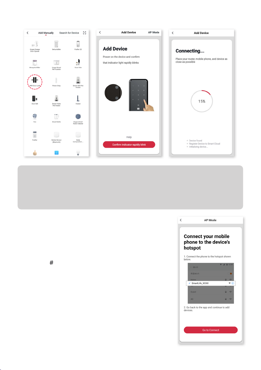
2. Select the type of device you want to connect
to.
3. Short press ‘3,’ then ‘ ’ on the keypad
to initiate pairing mode, then verify the
administrator by using the administrator’s
fingerprint, card or password.
4. Number 8 on the keypad will flash rapidly,
indicating the device is in pairing mode.
5. Follow the prompts on the app screen to
finalise the connection.
14
Page 15
NOTES
• Once paired, a voice will say “Added successfully.”
• If pairing has failed, the voice will say “Add failure.” If this occurs,
attempt to connect again.
Pairing with AP Mode
If unable to connect via the standard Wi-Fi pairing
method, try the AP Mode.
1. While in the pairing mode (with number
8 flashing rapidly on the keypad), press 3
then once again to transition to AP pairing
mode. The number 8 will now flash slowly.
2. Within the SmarterHome app, select the
’AP Mode’ from the top right, and confirm if
the indicator light is flashing slowly.
3. The lock will create a temporary Wi-Fi
hotspot, and the App will prompt you to
connect to this. Follow the onscreen prompts
to select the correct hotspot from your
device’s Wi-Fi options, then return to the app
to finalise the connection.
15
Page 16
USING THE APP (cont’d)
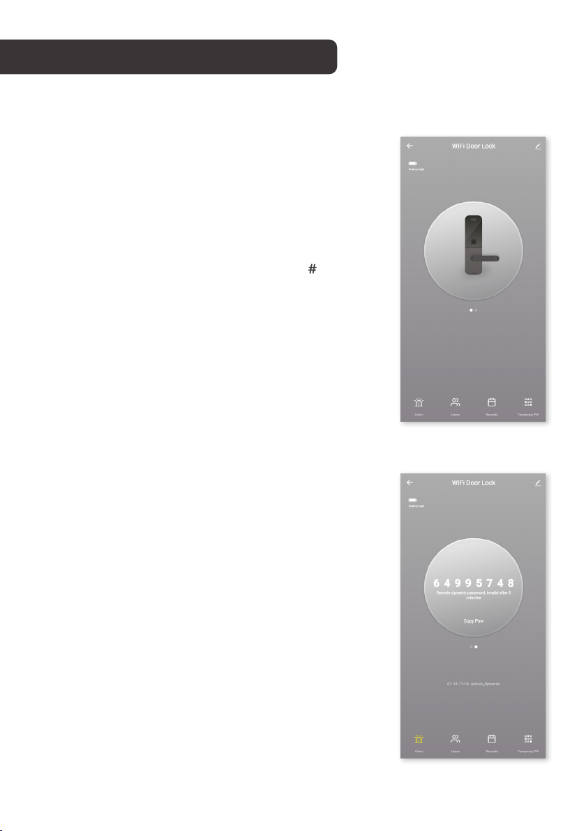
Using the app
After successfully configuring, the lock will be
shown on the app’s home page. Tap to enter its
control page.
Remote unlock
If trying to unlock the door without a card,
password, or fingerprint, you can use the app
to approve a remote unlock. Press 4 & on the
keypad to request the remote unlock. Then, in the
app, tap the lock icon when it flashes to approve
the remote unlock request. The door will now
unlock.
Remote dynamic password
To set a dynamic, temporary password which
expires after 5 minutes, swipe to the second
screen of the door lock’s control page and tap
on the lock icon to generate a password. You
can click to copy the password to your phone’s
clipboard, ready to paste and send to whoever
needs access.
16
Page 17
Temporary password
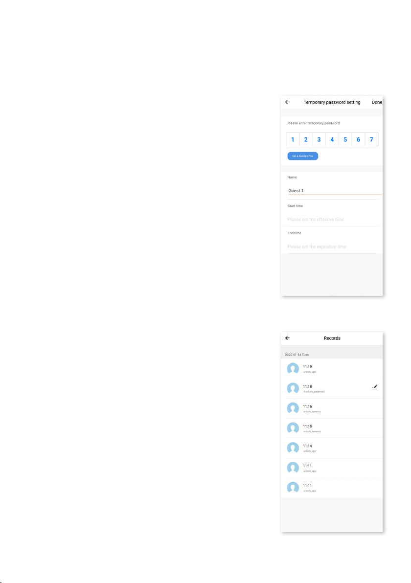
To schedule a longer-lasting temporary password,
with personalised or random code options and
the ability to set names and active dates, tap the
‘Temporary PW’ icon at the bottom right of the
control page. You can set for current time periods
(already in progress) or for future time periods
which will become activate upon their scheduled
start time.
Records and Alarm logs
You can view complete logs of how many times
the lock has been used each day, down to the
exact time, by going to the Records page from
the control page. Similarly, failed attempts to
unlock the door can be viewed in the Alarms tab.
Doorbell alarm will log when the doorbell is rung.
17
Page 18

TROUBLESHOOTING
Cannot enter the Wi-Fi pairing mode
• Ensure at least one administrator has been added.
• Follow steps to pair device with Kogan SmarterHome app.
• Please make sure that you are connecting with 2.4G Wi-Fi network, 5G Wi-Fi
networks are not supported at the moment.
• Please try with the AP pairing mode to enhance compatibility and try again.
• In extreme cases, the Wi-Fi router may not be compatible with the device.
Time-out error when connecting to SmarterHome app
• Please check your Wi-Fi signal and try again.
Voice prompts that door is locked, but it is not.
• This is likely due to the incorrect left and right opening door configuration.
• Check back to steps 1 and 6 of the installation steps (pages 5 and 9,
respectively) to ensure that the ‘dot’ position matches that of the door
configuration.
If you require further troubleshooting assistance,
head online to help.kogan.com
18
Page 19

SPECIFICATIONS
Dimensions
Dimensions 270 x 63 x 24mm
Weight 1.9kg
General
Capacity Up to 100 fingerprints or PINs
Water Resistant IP54
Sensor Semiconductor
Performance
Battery 4 x AA (not included)
DPI 500
Identify time 0.3s
Power
Battery Life ~12 months (10 entries per day)
Supply voltage 6v
Low voltage warning 4.6v
Standby current <=50mA
Note:
• Design and specifications are subject to change without notice.
• Weight and dimension shown are approximate.
19
Page 20

Need more information?
This is a Quick Start Guide, and we hope that this has
given you the assistance needed for a simple set-up.
For the most up-to-date guide for your product,
as well as any additional assistance you may require,
head online to help.kogan.com
 Loading...