


Type CL-2 = Compact-Light
MOTORGERÄTEFABRIK
94163 ENTSCHENREUTH
(0 99 07) 89 10-0 - Fax (0 99 07) 10 42
www.koeppl.com info@koeppl.com
The basis for working with the 2-wheel tractor type Compact-Light is that you read, understand and follow this operating manual and that for the
attachments as well as the engine
manufacturer’s operating manual.
You may not commence with the operation before having done
so
.
Rev. date / Edition
12.11.2012 - No. 02-2012
Für künftige Verwendung aufbewahren!
Retain for future reference!
Operating manual
for
2-wheel tractor
Compact
-L
ight = CL-2
CL10-2 / CL13-2 SNOW / CL14-2

Page 2
Version 02-2012
Notes
Compact-Light
Translation of the original operating manual
Translation of the original operating manual

Page 3
Version 02-2012
Table of contents
Compact-Light
Table of contents
Table of contents .................................................................................................................................. 3
Foreword ............................................................................................................................................... 4
Appropriate use .................................................................................................................................... 5
General safety instructions .................................................................................................................. 6
1.
Possible hazards in dealing with the 2-wheel tractor .............................................................................. 6
2.
Explanation of the safety symbols used ............................................................................................................ 6
3.
Hazards due to accessories ............................................................................................................................. 7
4.
Noise / vibration values ................................................................................................................................... 7
5.
Sources of danger .......................................................................................................................................... 8
6.
Lighting devices on single-axle tractors ............................................................................................................ 9
7.
Operator position, danger area ........................................................................................................................ 9
8.
Requirements for the operating personnel ...................................................................................................... 11
9.
Personal protective equipment....................................................................................................................... 11
10. Safety measures at the place of work ............................................................................................................ 12
11. General safety instructions ............................................................................................................................ 12
12. Protective devices ......................................................................................................................................... 13
13. Leaving the 2-wheel tractor ................................................................................................................ 14
14. Safety of attached devices ............................................................................................................................ 14
15. Brakes ......................................................................................................................................................... 15
16. Engine ......................................................................................................................................................... 15
17. Tyres, screwed connections........................................................................................................................... 15
18. Operating devices ......................................................................................................................................... 15
Transport ............................................................................................................................................ 16
1.
Tractor size / machine dimensions ................................................................................................................. 16
2.
Technical data .............................................................................................................................................. 17
3.
Transport ..................................................................................................................................................... 18
Operation ............................................................................................................................................ 19
1.
Commissioning ............................................................................................................................................. 19
2.
Steering shaft adjustment ............................................................................................................................. 20
3.
Starting the 2-wheel tractor ............................................................................................................... 21
4.
Shifter .......................................................................................................................................................... 22
5.
Power take-off engagement/disengagement ................................................................................................... 23
6.
Engine ......................................................................................................................................................... 24
7.
Throttle lever ............................................................................................................................................... 25
8.
Active steering.............................................................................................................................................. 26
9.
Rapid-change device flange ........................................................................................................................... 28
10. Parking foot ................................................................................................................................................. 29
11. Operating hour meter ................................................................................................................................... 30
Faults .................................................................................................................................................. 31
1.
Faults and their remedy ................................................................................................................................ 31
Maintenance ....................................................................................................................................... 33
1.
Hydraulic drive ............................................................................................................................................. 33
2.
Power take-off drive ..................................................................................................................................... 36
3.
Wheel drive .................................................................................................................................................. 36
4.
Engine ......................................................................................................................................................... 38
5.
Drive wheels, wheel motors .......................................................................................................................... 38
6.
Attached devices .......................................................................................................................................... 39
7.
General ........................................................................................................................................................ 39
8.
Safekeeping and storage ............................................................................................................................... 39
9.
Maintenance schedule ................................................................................................................................... 40
Appendix ............................................................................................................................................. 41
1.
Lubricants / adhesives .................................................................................................................................. 41
EU Conformity Declaration ................................................................................................................. 42

Page 4
Version 02-2012
Foreword
Compact-Light
Foreword
Before putting the Compact-Light 2-wheel tractor into operation, it is absolutely
essential to read and follow the instructions regarding appropriate use, the operat-
ing manual and the safety instructions as well as the operating manuals for the attached devices that will be operated with the 2-wheel tractor!
The guarantee only applies in the case of proper operation!
Dear customer, you have made the right choice!
Although the available choice is large, you have decided on a 2-wheel tractor.
We are particularly pleased about that. We will do our best to satisfy you for many
years to come.
We hope you will be our best advertisement from now on.
The following points distinguish our product:
•
The appliance is very well balanced, you can work without effort.
•
It is equipped with an outstanding engine.
•
Maintenance costs are hence very low.
•
The operation is simple and effective.
•
The supply of spare parts is guaranteed and takes place promptly.
•
Optimum customer service is at your disposal at all times.
The Compact-Light 2-wheel tractor is the result of decades of experience and can
therefore be used practically and continuously.
The company is constantly working on the further development of all of its
machines and appliances. We therefore reserve the right to make changes to the
form, technology, weight and equipment of the scope of supply. Please understand
that no claims can be derived from the specifications and illustrations contained in
this manual.
IF YOU HAVE ANY REQUESTS FOR IMPROVEMENT, PLEASE LET US
KNOW!
Page 5
Version 02-2012
Appropriate use
Compact-Light
Appropriate use
The 2-wheel tractor type Compact-Light, in conjunction with the respective original
attached device, is designed exclusively for normal use and work in agriculture and forestry,
such as the mowing of grass and meadows as well as the performance of winter services:
- for snow hoeing, snow clearing, mowing, flail mowing, all-purpose mowing, hay mak-
ing, sweeping and the scattering of sand and fertiliser
•
The conditions specified in the quotation and in the confirmation of order are decisive. Any
other use is construed as being inappropriate. The manufacturer shall not be liable for any
damages resulting from this; the user alone bears the risk.
•
This work is permitted only if the engine sizes, wheel sizes and environmental conditions
are suitable.
•
The 2-wheel tractor (Type Compact-Light) may be used, maintained and repaired
only by persons who are familiar with this work and who have been instructed about the
hazards.
•
The 2-wheel tractor may not be used on steep slopes.
•
Unauthorised conversions and alterations to the 2-wheel tractor are forbidden for safety reasons!
•
Relevant regulations governing the prevention of accidents as well as the generally accepted
regulations governing health and safety at work and road traffic rules must be complied
with.
Important!
The operating, service and maintenance conditions for the 2-wheel tractor specified in
this operating manual are prerequisites for appropriate use and must be strictly adhered
to.
Warning!
If the machine is used for any other purpose than that stated above or is driven with a
higher power than is permitted, this can result in:
•
dangerous situations for people and
•
damage to property.
Warning!
The manufacturer is not aware of any inappropriate or prohibited uses of the machine. The
improper attachment of additional devices or the attachment of additional devices and
parts not purchased from the company exclude liability for any resulting damage.

Page 6
Version 02-2012
General safety instructions
Compact-Light
General safety instructions
1. Possible hazards in dealing with the 2-wheel tractor
In the case of incorrect operation or misuse, there is a danger of
•
injury to or death of the operator,
•
damage to the 2-wheel tractor and other property belonging to the user,
•
impairment of efficient working with the 2-wheel tractor
All persons who are involved with the start-up, operation, service and maintenance of the 2-
wheel tractor must
•
be appropriately qualified,
•
observe and follow this operating manual precisely!
It’s your safety that is at stake
!
2. Explanation of the safety symbols used
The following symbols are used in this operating manual:
Warning!
This symbol indicates important safety information in this operating manual.
This symbol indicates a possibly dangerous situation. Serious injuries may result from failing to
follow the instructions. Read the following instructions carefully and also inform other operating
personnel.
Caution!
This symbol indicates a possibly dangerous situation.
Slight injuries may result from failing to follow the instructions.
Important!
This symbol denotes safety tips and other useful information.
Wear safe
ty glasses
Wear protective
gloves
Wear safety shoes
Read and follow the
operating manual and
safety instructions
before putting into
operation!
Switch off the engine and
re
move the spark plug cap
before repair, mainte-
nance and cleaning!
Wear ear protectors
Never reach into the
crushing danger zone if
parts can
still move there
Warning of a hot
surface
Switch off the mowing attachment
and the engine before working on
the cutting tool
Page 7
Version 02-2012
General safety instructions
Compact-Light
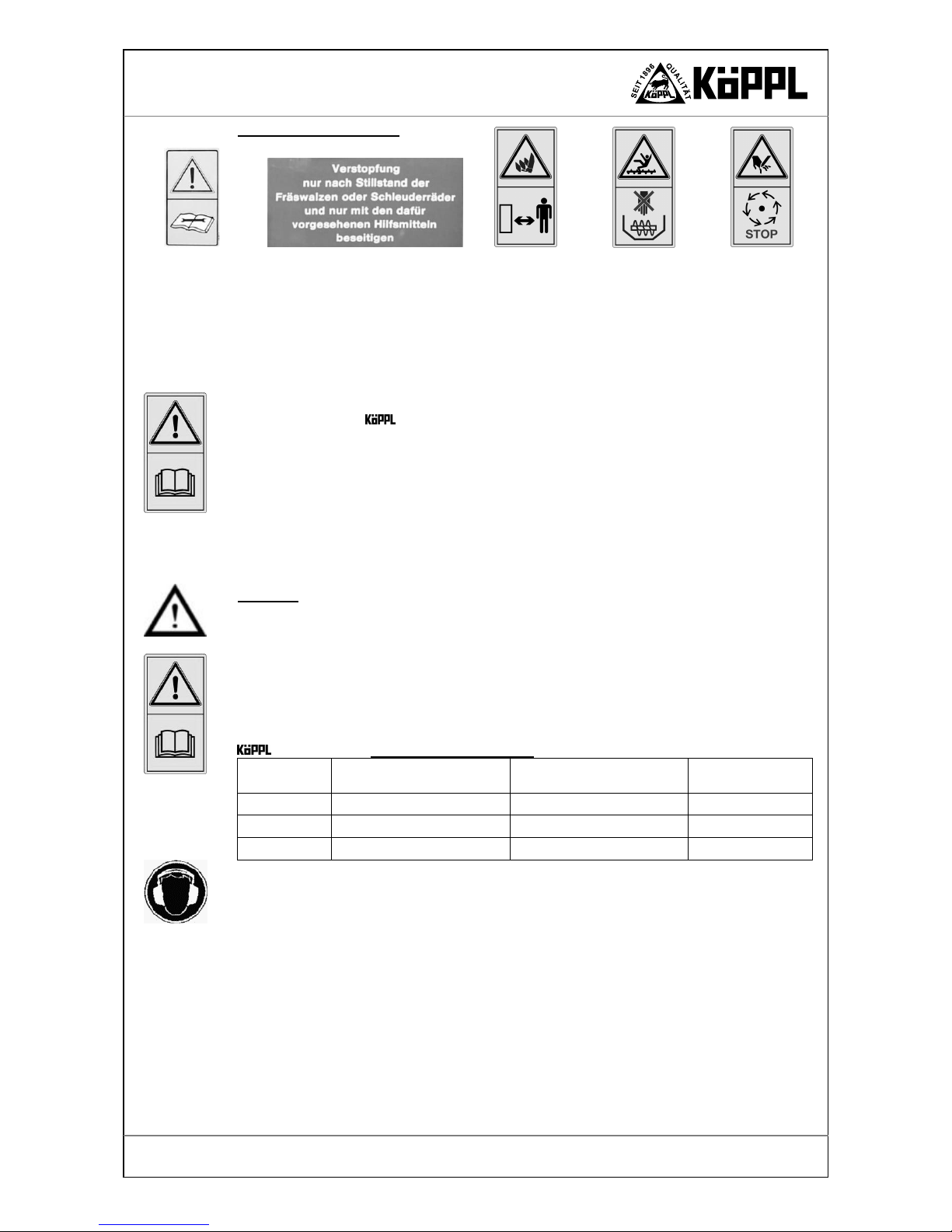
Snow hoe warning notices
3. Hazards due to accessories
Attached devices, mowing devices and any other additional devices used must not disable the
safety devices of the 2-wheel tractor.
4. Noise / vibration values
Caution!
Long periods of exposure to noise and vibrations lead to damage to health. Wear ear protectors and adapt your working hours.
Noise information (sound power level EN ISO 3744) - emissions
Noise information (sound pressure level EN ISO 11201) - immissions
Vibrations (hand/arm vibrations DIN 45675 Part 8) - immissions
The A-weighted sound power level and the A-weighted emission sound pressure level of the
2-wheel tractor, without additional devices, at the operator's ear are
Version Sound power level
[dB(A)]/[rpm]
Sound pressure level
[dB(A)]/[rpm]
Vibrations
[m/s²]
CL10 98,8 87,3 4,2
CL13 98,2 86,8 4,4
CL14 98,9 88,4 4,6
- Wear ear protectors
Emissions of a noise level can lead to disturbances of acoustic signals. Other vehicles may
not be noticed – particular caution is required!
Depending on the attached device, an increase in the sound pressure level of up to 4.5 dB(A) is
to be expected - exact data is given in the respective operating manual.
•
Measurements took place in the open air, based on EN ISO 3744 (sound power level) and
EN ISO 11201 (sound pressure level).
•
The measuring instrument used: NOR 116 sound level meter, Norsonic, Norway - complies
with the IEC 651 and 804 class 1 standard.
•
Engine speed = highest engine operating speed
•
Radius of the semicircular measurement area = 4 m.
Read the opera
t
ing
manual before
putting into
operation.
Eliminate blockages only after the rotary
grinder and chopper wheels have come to a
standstill and only with the aids provided.
Danger of being caught up, wound in,
drawn in or trapped.
Keep a sa
fe distance
.
Danger due to parts
being flung when the
engine is running.
Keep a safe distance.
Danger of being
caught up, wound in,
drawn in or trapped.
Keep a safe distance.
Danger due to
rotating tools.
Switch the engine off
and wait until the
tools come to a halt
Page 8
Version 02-2012
General safety instructions
Compact-Light
2. Vibration measurements took place in accordance with EN 1033.
Measuring devices
Vibration measuring instrument: CASTLE GA 2003 HARM
Operating conditions
•
Fuel tank approx. 50 % full.
•
Steering shaft adjusted to the body height of the operator.
•
Appliance run-in and at operating temperature.
•
Measured on the steering shaft in accordance with EN 12733.
•
Engine speed = highest engine operating speed
5. Sources of danger
The 2-wheel tractor may be used on both commercial and private properties in accordance with road traffic laws.
•
Check that the unit is safe to operate and to be used in traffic each time before putting it into
operation!
•
Observe the generally applicable regulations for safety and the prevention of accidents in
addition to the instructions in this operating manual!
•
When using the 2-wheel tractor on public roads, the stipulations of the respective national road traffic laws (in Germany: StVZO) in their current versions apply.
•
Familiarise yourself with all devices and controls as well as their functions before starting
work. Make sure that all protective devices have been attached properly! Doing so during
the work assignment is too late!
•
The user is responsible for the safety of third parties in the working area!
•
It is forbidden to enter or remain in the working and danger area of the 2-wheel tractor!
•
Before starting up, check the immediate vicinity - children!
•
Ensure that your field of view and the lighting conditions are adequate!
•
The driver should wear tight-fitting clothes. Avoid loose-fitting clothes. Wear sturdy shoes!
•
Do not leave the engine running in closed rooms – the exhaust gases are harmful to health
and may under certain circumstances lead to death!
•
Be careful when handling fuel – increased risk of fire! Never refill the fuel tank in the proximity of open flames, igniting sparks and hot engine parts. Do not smoke when refuelling!
•
Before refuelling, switch off the engine and remove the ignition key (if one exists). Do not
refuel in closed rooms – risk of explosion!
•
Use a suitable pouring aid (e.g. a funnel). If possible, refuel only in the open air with the
engine switched off and cold.
•
Do not spill fuel – risk of fire!
•
If you have spilt fuel, clean all parts and push the motor mower away from this place before
starting it.
•
Do not inhale petrol vapours – risk of cancer due to benzene content; use lead-free and benzene-free petrol if possible – refer also to the engine manufacturer’s operating manual!
•
In order to avoid the risk of fire, keep the tractor clean!
•
Be careful when handling brake fluids and battery acid – they are toxic and caustic!
•
Switch off the engine and pull off the spark plug cap before performing maintenance and
cleaning work.
•
Particular caution is necessary when coupling or uncoupling attached tools to or from the
tractor!
•
Make sure that all protective devices have been attached properly!
•
Observe permissible axle loads, overall weights and transport dimensions!
Page 9
Version 02-2012
General safety instructions
Compact-Light
6. Lighting devices on single-axle tractors
Distinction must be made here as to whether the single-axis tractor
•
is guided by a pedestrian via the steering shafts or,
•
is driven from a sulky (single-track trailer) or
•
is driven from a trailer.
In the dark, or when necessitated by the weather, single-axle tractors guided by pedestrians via
the steering shafts require at least a single, non-dazzling lamp with a white light, which must
be affixed to the left-hand side (UK: right-hand side) or carried by hand so that its light is clearly visible to oncoming traffic (from the front) or overtaking traffic (from the rear) (Article 50,
paragraph 2, German Highway Code and Article 17, paragraph 5, German Highway Code).
If a single-axle tractor with a trailer is transported on a public road, no operating permit is required up to a design-related top speed of 6 km/h. The name and place of residence of the keeper
of the vehicle must be displayed by a sign on the trailer. A driving licence is not required, however. The driver of the vehicle must be qualified to drive it. Lighting devices etc. must be present.
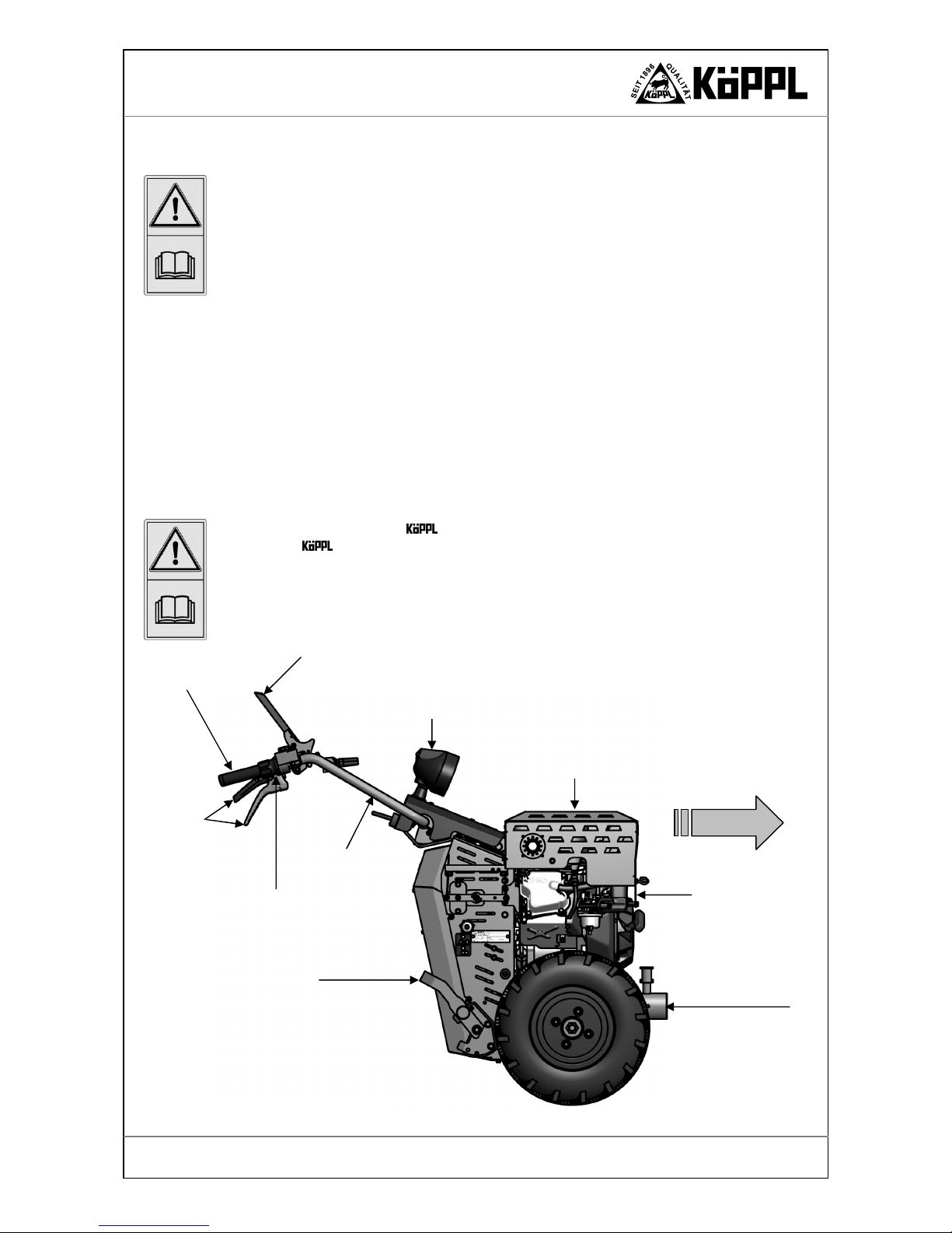
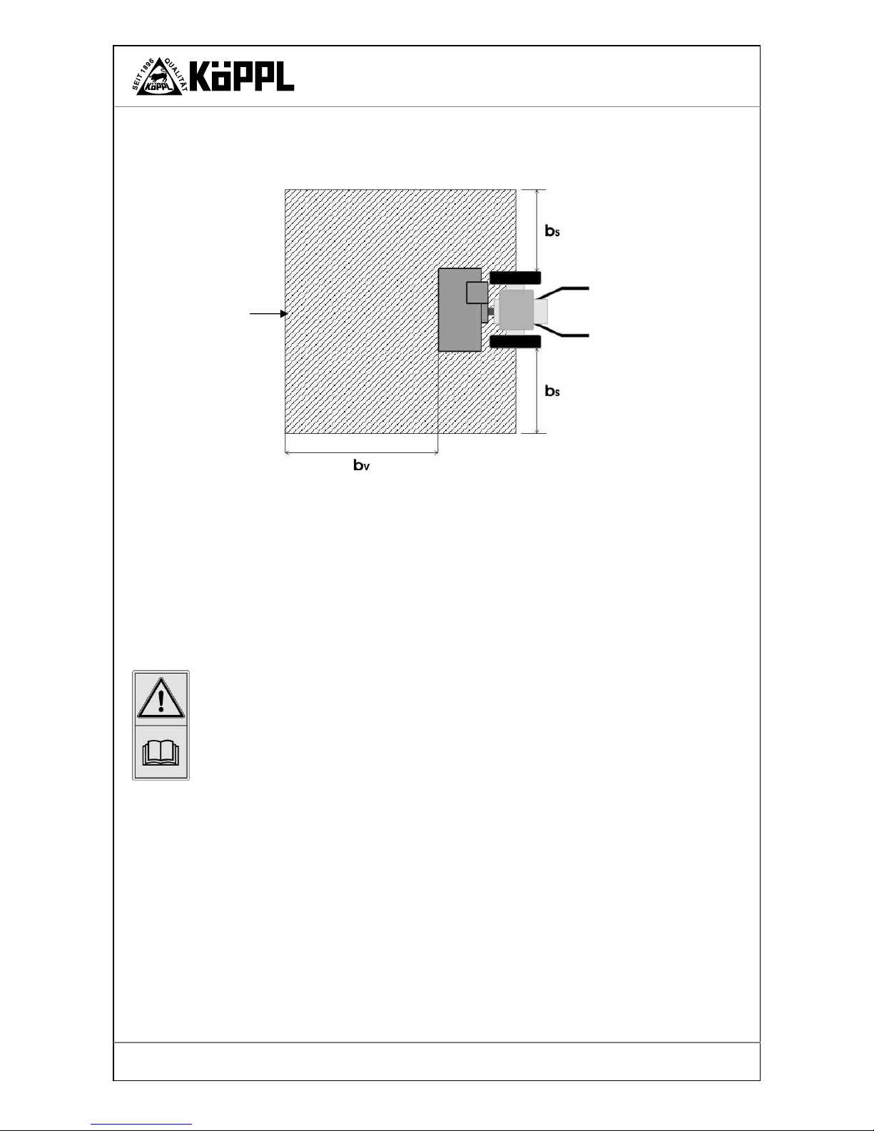
7. Operator position, danger area
The operator position on the 2-wheel tractor is located at the two steering shafts (controls)
behind the 2-wheel tractor.
Fig. 1. Operator position.
Direction of
travel
Engine
Rapid-change flange
Operator position
Safety stop lever
with wheel and power take-off drive
Parking foot
operating position
Steering shaft
height-adjustable
Steering lever
Engine cowling
optional
Working headlight
optional
Twist-grip
Forward/reverse
Page 10
Version 02-2012
General safety instructions
Compact-Light
It is forbidden to enter the danger area (B) during work.
This area begins in the middle of the wheel axle and extends to the sides and to the front by varying distances, depending on the attached tool.
Where
•
Snow hoe bs = 25 m bv = 25 m
•
Snow plough blade bs = 10 m bv = 10 m
•
Mowing bars bs = 10 m bv = 10 m
•
AZM-S bs = 2 m bv = 5 m
•
AZM-A bs = 25 m bv = 25 m
•
Belt haymakers bs = 10 m bs = 10 m
•
Flail mowers bs = 20 m bv = 20 m
•
Sweeping machine bs = 5 m bv = 5 m
Also refer to the operating manuals for the respective attached devices!
Working on slopes with a gradient higher than 25% or in uneven terrain
On slopes with a gradient of over 40% or in uneven terrain, the device can slip or tip over; the
danger zone is extended by the possible slipping or tipping area of the machine.
•
Check the terrain before starting work.
•
Select the correct tyres: twin tyres, additional iron slope wheels, spiked rollers…
•
Use the maximum possible track and axle width.
•
Check the tyre pressures.
•
Safety shoes type S2 with non-slip soles are absolutely necessary. Work with crampons if
necessary.
•
Keep persons clear of the danger area.
•
Adapt your working speed to the surroundings.
•
Keep a constant watch on the lie of the terrain.
•
Pay attention to the weather – increased risk of accident in wet weather
•
Danger due to forced posture over long periods when working in difficult terrain – take sufficient breaks!
Danger area B

Page 11
Version 02-2012
General safety instructions
Compact-Light
8. Requirements for the operating personnel
The minimum age for operators is 16 years.
Only authorised persons may work with the 2-wheel tractor type Compact-Light.
No operating permit and no driving licence is required for single-axle traction and working machines guided by pedestrians via steering shafts. If the visibility makes it necessary, at least one
non-dazzling white light is to be attached at the front and at the rear on the left-hand side (UK:
right-hand side).
If a single-axle tractor and trailer is transported on a public road, no operating permit is required
up to a design-related top speed of 6 km/h. The name and place of residence of the keeper of the
vehicle must be displayed by a sign on the trailer. A driving licence is not required, however. The
driver of the vehicle must be qualified to drive it. Lighting devices etc. must be present.
The operator is responsible for the safety of third parties in the working area.
The responsibilities for different activities on and with the 2-wheel tractor must be clearly
defined and adhered to. Unclear competences are a safety risk.
The user must:
•
make the operating manual available to the operator and
•
ensure that the operator has read and understood it.
9. Personal protective equipment
For operation
Wear type S2 safety shoes.
wear work clothes that offer sufficient protection against the sun.
You should wear suitable ear protectors when working.
For cleaning
Wear sturdy safety gloves (leather) to protect against sharp objects (attached devices).
For grinding the mowing blades
Wear safety goggles
> 25% < 25%
Fig. 2. Working on slopes
Check the angle of inclination
of the terrain with a spirit level
Up to 80%
100 cm
25 cm = 25%
W
Terrain
Page 12
Version 02-2012
General safety instructions
Compact-Light
10. Safety measures at the place of work
•
When starting the engine, the traction and attached device drives must be disengaged (i.e.
the safety stop lever is not depressed; see fig. 2, page 13).
•
The driving speed must always be adapted to the environmental and load conditions. Avoid
sudden turns when driving up, down or across a slope. Never disengage the clutch and/or
shift gear on slopes.
•
Couple trailers and attached devices according to the regulations. The driving, steering,
braking capability and tipping behaviour will be affected by attached devices. Therefore
make sure that steering and braking capabilities are sufficient and adapt your working speed
to the respective environmental conditions!
•
Persons fitted with a cardiac pacemaker must not touch electrically conducting parts of the
ignition system when the engine is running.
•
Before starting to drive, check the brakes and their function.
•
Remove objects from the work area (e.g. planks, cables, stones etc.).
•
Keep hands and feet away from moving parts during operation.
•
Ensure that the work area is sufficiently well illuminated.
•
Drive at a right angle to the slope, never up or down the slope!
•
Never disengage the clutch and/or shift gear on slopes.
•
Never leave the operator position during work.
•
Do not alter or repair supporting and safety-relevant parts (frame, axles etc.).
•
In the case of damage to the appliance, switch it off immediately. Remove the spark plug
cap and have the damage repaired!
•
If the appliance is to be used for mowing crops that are classified as foodstuffs, parts which
come into contact with the foodstuffs must not be lubricated with machine oil or grease or
protected against rust.
•
Avoid sudden turns when driving up, down or across a slope.
•
Driving downhill in neutral is forbidden! The appliance could roll away under its own
weight.
•
If there is a danger of slipping on a sloping terrain, an accompanying person must hold the
2-wheel tractor with a rod or a rope. The accompanying person must remain above the
vehicle at a safe distance from the working tools.
11. General safety instructions
•
Watch out for fuel and oil leaks and eliminate them if necessary.
•
Check screws, nuts and bolts regularly for tightness and tighten them if necessary – after the
first time of use and if circumstances demand.
•
Lubricate all sliding or moving parts (e.g. Bowden cables etc.) with a little grease or lubricating oil, especially after cleaning with a high pressure cleaner.
Page 13
Version 02-2012
General safety instructions
Compact-Light
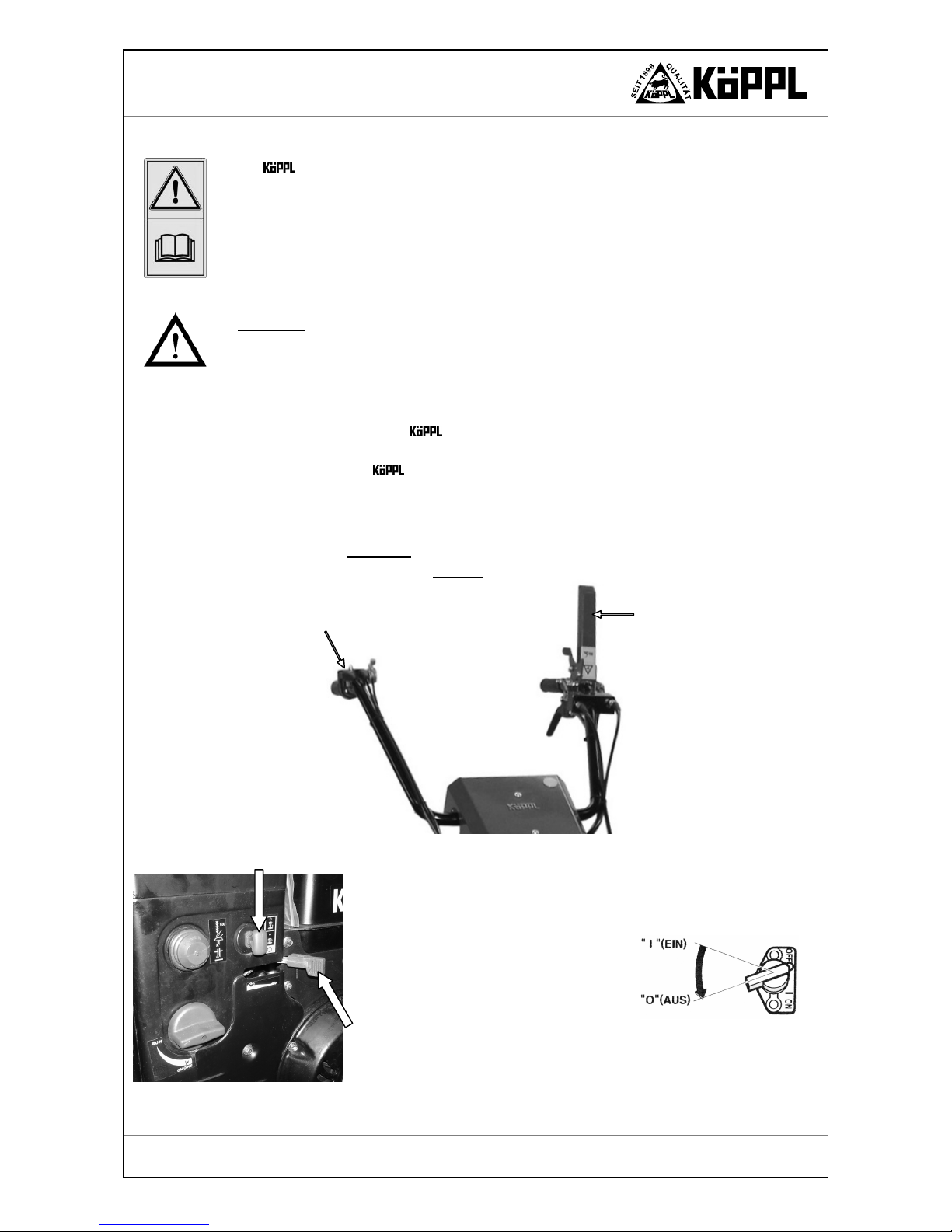
Fig. 3. Safety stop lever – stop position.
Safety stop lever
‘stop’ position
Robin EX40 engine
Ignition switch
12. Protective devices
The 2-wheel tractor is equipped with a safety stop lever on the steering shaft (left), which
disengages the traction drive or power take-off drive when released – i.e. the engine continues to
run, but the machine and the attached device stop (for stop position see fig 3). The engine can be
switched off only by the ignition key (if there is one) or by the engine stop switch.
The safety stop lever serves as an emergency stop switch in dangerous situations where fast
switch-off is required. It swivels automatically into the ‘STOP’ position when released.
Stop the 2-wheel tractor immediately if there are any malfunctions of the safety stop lever.
Have malfunctions rectified immediately!
Warning!
The engine runs on due to the centrifugal ma!
Tools running on – danger of injury!
•
In order to start the machine, the Bowden cable shifter must be placed in the 0 position and
the safety stop lever must be placed in the stop position - see fig. 3.
•
During operation of the 2-wheel tractor the safety stop lever must be depressed –
operating position.
•
It is forbidden by to leave the safety stop lever/ V-belt tensioning lever in the operating position when the machine is to be cleaned, maintained or left – e.g. in order to clean
the snow hoe. First bring the machine to a halt, switch off the engine and then clean the tool.
It is forbidden
to tie down the safety stop lever / tensioning lever or
to bind it with adhesive tape!
Motor Rato
SNOW
1 - Place the throttle lever first in the SLOW po-
sition and then in the STOP position.
2 - Remove the safety key .
Also refer to the engine manufacturer’s
operating manual!
Fig. 4. Switching the engine off.
Twist-grip
forward/reverse + speed
Page 14
Version 02-2012
General safety instructions
Compact-Light
The protective devices
•
have been installed for the safety of the operator and,
•
must not under any circumstances be modified, removed or circumvented by means of modifications to the 2-wheel tractor.
The safety stop lever serves as an EMERGENCY-OFF switch which is to be released in dangerous situations where fast switch-off/stopping is required. It then returns automatically to the
‘STOP’ position.
13. Leaving the 2-wheel tractor
•
Set the 2-wheel tractor down on the ground, switch off the engine and remove the ignition key (if there is one).
•
When leaving the 2-wheel tractor, secure it against rolling away and use by unauthorised persons by means of wheel chocks.
•
Never leave the 2-wheel tractor unattended if the engine is still running.
•
Never leave the operator position at the steering shaft when driving.
•
Close the petrol tap when parking the 2-wheel tractor!
14. Safety of attached devices
Fundamental rule:
Check that the unit is safe to operate and to be used in traffic each time before putting it into operation!
•
There is a risk of injury when coupling attached devices. Be especially careful!
•
Attached devices may only be attached when the engine is switched off and the PTO drive
is disengaged.
•
Secure the 2-wheel tractor and the attached devices against rolling away (parking
brake, wheel chocks).
•
Attach the transport lock and safety device and place them in the protective position.
•
Connect the attached devices according to regulations and fasten them only to the prescribed fittings.
•
It is not permitted to ride on the attached device of the tractor during work or
transport.
•
Observe permissible axle loads, overall weights and transport dimensions!
•
Check and attach transport equipment (lighting, warning devices, protective devices).
•
Switch the appliance off immediately in the case of damage; remove the ignition key of the
2-wheel tractor if there is one (only with electric starter) and have the damage re-
paired.
•
Place protective and safety devices in the protective position again after the repair work is
completed. Only then is operation allowed again.
•
Check the protective devices and working devices for wear.
•
There are crushing and cutting zones on externally powered parts (e.g. hydraulics.
•
It is forbidden to enter or remain in the working, rotating and swivelling area!
Keep a safe distance!
•
Before starting work, remove all foreign bodies from the area to be worked. Beware of foreign bodies during operation!
•
Before starting work, remove all foreign bodies from the area to be worked. Beware of foreign bodies during operation!
•
Be particularly careful when working on steep paths and on slopes – danger of tipping over!

Page 15
Version 02-2012
General safety instructions
Compact-Light
Drive at a right angle to the slope if possible.
•
Disengage the device drive (power take-off) when driving outside the working area. The
2-wheel tractor must be raised into the transport position.
•
Never work on the attached device when the engine is running; switch the engine off in order to carry out such work.
•
Persons must not stand between the tractor and the attached device if the tractor is not
secured against rolling away by means of wheel chocks.
•
Observe the generally applicable regulations for safety and the prevention of accidents in
addition to the instructions in this operating manual.
•
The mating surfaces of the rapid-change flange on the basic device and on the attached device must be clean; they must be cleaned if necessary.
•
The mating surfaces must be greased with special long-life grease (see appendix).
•
If protective devices and working tools are subject to wear they should be inspected at regular intervals and replaced if necessary!
15. Brakes
•
The appliance is braked by load-holding valves.
•
Adjustment and repair work on the load-holding valves may be carried out only by specialist workshops.
16. Engine
•
Do not leave the engine running in a closed room – danger of poisoning!
•
Always switch the ignition off and close the petrol tap when turning the engine off!
17. Tyres, screwed connections
•
When working on the wheels, ensure that the tractor is parked safely and secured against
rolling away!
•
Repairs to the tyres may be carried out by specialists using suitable mounting tools!
•
There is a risk of explosion if the tyres are over-inflated!
•
Check the tyre pressures regularly!
•
Check the wheel motor bolts for tightness after the first 10 hours of operation and then all
every 8 hours of operation.
18. Operating devices
•
Check the function of the brakes before starting to drive!
•
Shift down in good time before driving downhill!
•
Switch off the tractor immediately if malfunctions occur in the steering or brakes. Have
malfunctions rectified immediately!

Page 16
Version 02-2012
Transport
Compact-Light
Transport
In order to avoid damage to the machine and life-threatening injuries when transporting the machine, it is essential to pay attention to the following points:
•
Transport work may be carried out only by persons who are qualified for such work, observing the safety instructions.
•
The machine may be raised only at the points intended for the purpose and without attached
devices.
•
When transporting on a trailer, it is essential to secure the machine against slipping and rolling away. Always switch off the engine.
•
Use suitable ramps for loading and unloading.
•
Never transport the engine with the fuel tank or the fuel tap open. Refer also to the motor
manufacturer’s operating manual!
•
Follow the national road traffic regulations when driving on public roads.
•
Also read the chapter ‘General safety instructions’.
1. Tractor size / machine dimensions
Tyres
a
[mm]
b
[mm]
c
[mm]
g
[mm]
4.00 x 8 AS 1.220 1.112 269 602
Compact-Light = CL.
a
b
c
g
Forwards

Page 17
Version 02-2012
Transport
Compact-Light
2. Technical data
CL10-2 CL14-2
CL13-2
SNOW
Driving speed
Wheels 4.00 x 8 AS
Forwards
Reverse
0 – 6 km/h
0 – 3 km/h
0 – 6 km/h
0 – 3 km/h
0 – 6 km/h
0 – 3 km/h
No. of gears/
Settings
Infinite
forward/reverse
Infinite
forward/reverse
Infinite
forward/reverse
Power take-off speed, max.
approx. 1.050 rpm approx. 1.050 rpm
approx. 1.050 rpm
Power take-off
engagement /disengagement
yes yes yes
Rapid-change device flange
Standard Standard Standard
Engine
Robin
Petrol
EX27
6,6 kW
9,0 HP
Robin
Petrol
EX40
10,3 kW
14,0 HP
Rato
Petrol
390 SNOW
9,5 kW
13,0 HP
Active steering
Standard Standard Standard
Wheels 4.00 x 8 AS
Standard Standard Standard
Iron slope wheels
Standard Standard Standard
Weight [kg]
without tyres and
without attached device
122 128 128
Tyre type
Tyre size
Track width Pressure
Field tyres
4.00 x 8 AS
4.00 x 10 AS
5.00 x 10 AS
60 cm
61 cm
71 cm
1,5 bar
Wide tyres AS
16x 6.50 x 8 AS
18 x 9.50 - 8 AS
20 x 8 - 10 AS
77 cm
83 cm
84 cm
1,5 bar
Turf tyres
18 x 9.50 - 8 84 cm
Lamella tyres
Snow tyres
4.00 x 8 61 cm
1,5 bar
Optionally with caterpillar drive
Filling quantities
Hydraulic system
Mobil DTE 10 Excel 68
alternatively oil*
according to DIN 51524-3 (ISO VG68)
CAUTION!
use only zinc-free oils
approx. 1.9 l
Internal combustion engine
see operating instructions
* if alternative oils are used, an oil change must be carried out after every 25 hours of operation.

Page 18
Version 02-2012
Transport
Compact-Light
3. Transport
The 2-wheel tractor is delivered ready for operation.
Unpacking
•
Remove the cardboard box and the film.
The generally recognised and applicable regulations for safety and the prevention of accidents must be adhered to when transporting the 2-wheel tractor!
•
Ensure that all protective devices are properly attached.
•
Ensure that no protective devices have been damaged or rendered inoperable during
transport.
•
Check and attach transport equipment (lighting, warning devices, protective devices).
•
If protective devices and working tools are subject to wear they should be inspected at regular intervals and replaced if necessary!
•
Place protective and safety devices in the protective position again after transport. Only
then is operation allowed again.
•
Check the protective devices and working devices for wear.
•
Never transport the engine with the fuel tank or the fuel tap open. Refer also to the engine
manufacturer’s operating manual!
Fig. 5. Compact-Light CL.

Page 19
Version 02-2012
Operation
Compact-Light
Operation
In order to avoid damage to the machine and life-threatening injuries when putting the
machine into operation, it is essential to pay attention to the following points:
You must have read and understood:
•
the engine manufacturer’s operating manual,
•
the operating manual for the respective attached device and
•
the operating manual for the 2-wheel tractor,
in particular chapter 1, ‘Safety and protective devices’.
You may not operate the 2-wheel tractor before having done so.
1. Commissioning
Warning!
Exhaust gases contain carbon monoxide!
They are highly toxic if inhaled and can lead to death.
Important!
During the first 20 hours of operation (the running-in period) the engine and the hydraulic
system should not be operated up to their performance limits.
After about 10 hours of operation, check that all screws, bolts and control parts on the
basic machine and attached devices are tight.
Important!
At temperatures under + 0° C you must allow the hydraulic drive to warm up for approx. 3
minutes at a low engine speed so that the oil can reach operating temperature and the drive can
function without problems. During this time
• the ‘Direction of travel’ twist-grip must be in the neutral / 0 position.
• the safety stop lever must be depressed.
The oil pump runs and the oil warms up.
After about 3 hours of operation, check that all screws, bolts and control parts on the basic machine and attached devices are tight.
The following items must be checked before putting into operation for the first time:
•
Check the engine oil – see the engine manufacturer’s operating manual.
•
Check the hydraulic oil.
•
Check all safety devices.
•
Check whether there is sufficient fuel in the fuel tank.
•
Check that all screws, bolts and controls on the 2-wheel tractor and the attached device are tight!
•
Remove all tools and foreign parts from the machine.
•
Adjust the steering shaft to the operator’s body size and in accordance with the purpose of
use.

Page 20
Version 02-2012
Operation
Compact-Light
2. Steering shaft adjustment
In order to be able to work optimally, you must adjust the steering shaft to suit your body size.
This adjustment is child’s play:
•
Stand in front of the 2-wheel tractor.
•
You should be able to stand in a relaxed position in front of the 2-wheel tractor with
slightly bent elbows. If that is not the case the steering shaft needs to be adjusted.
Adjusting the steering shaft: (See fig. 6)
•
Press lever C downwards until the steering shaft is released from the latch.
•
Hold the lever C and adjust the height.
•
The steering shaft can be locked further up or further down by releasing and latching lever
C.
•
You are now finished with the adjustment of the steering shaft.
Fig. 6.
Steering shaft adjustment
.
Lever C
Lever C

Page 21
Version 02-2012
Operation
Compact-Light
3. Starting the 2-wheel tractor
Warning!
If the traction and device drive is engaged, you could be run over, causing serious injuries.
The traction and device drive must be disengaged when starting the engine.
Do not stand with your feet near the attached working device.
To start the engine:
Follow the respective engine manufacturer’s operating manual when starting the engine – start
it according to the engine manufacturer’s operating manual.
Starting the 2-wheel tractor:
•
Before starting the machine, the twist-grip must be placed in the 0 position and the safety
stop lever must be placed in the start position - see fig. 7.
•
Turn the ignition switch to ON.
•
With most engine types (depending on the manufacturer) the shock lever must be closed
when the engine is cold – see the engine manufacturer’s operating manual.
•
The engine can now be started with the aid of the recoil starter.
•
The throttle should be opened about halfway for the start procedure.
•
Once the engine is running, bring the throttle lever slowly to the ¼ position and allow the
engine to warm up for a short time. Push the choke knob slowly back to the operating position if it has been pulled out. Also refer to the engine manufacturer’s operating manual
regarding this point.
•
At temperatures under + 0° C you must allow the hydraulic drive to warm up for approx. 3
minutes at a low engine speed so that the oil can reach operating temperature and the drive
can function without problems.
During this time
•
The twist-grip must be in the 0 position and
•
the safety stop lever (without PTO drive) must be depressed.
The gearbox drive runs with the engine and the oil warms up.
Fig. 7. Twist-grip.
Twist-grip in the 0-
position
Safety stop lever
in the start/stop position
Tensioning lever
- PTO engagement/
disengagement

Page 22
Version 02-2012
Operation
Compact-Light
4. Shifter
With the Compact –Light, forward and reverse driving with infinitely adjustable speeds and
neutral are possible.
Warning!
Place the Bowden cable shifter in the 0 position before starting!
When driving in reverse there is a danger of being crushed at narrow points or when turning (around trees).
Forward gear
Turn the twist-grip slowly towards the front, as shown in fig. 8.
Reverse gear
Turn the twist-grip slowly towards the rear, as shown in fig. 8.
Neutral position
Place the twist-grip in the 0-position - noticeable by the latching point. The machine stops, as if
fully applying the brakes.
With the locking nut the selected speed can be locked so that the twist-grip cannot move of its
own accord. If you wish to change the speed again, you must loosen the locking nut.
Fig. 8. Shifter positions – Twist-grip.
Throttle lever
Locking nut
Direction of
rotation
loosen
Direction of
rotation
lock
Direction of rotation
Direction of travel
Direction of rotation
Direction of travel

Page 23
Version 02-2012
Operation
Compact-Light
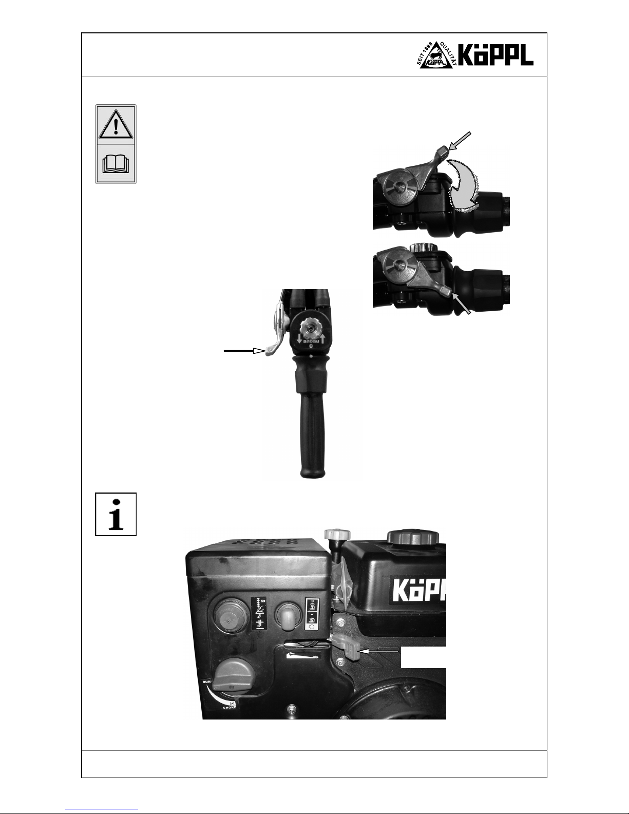
5. Power take-off engagement/disengagement
Warning!
Working devices are dangerous when switched on!
Make sure you keep a safe distance!
Engage the power take-off only when an accessory is attached.
Push the lever slowly downwards so that the attached device comes slowly up to speed.
Never reach into the crushing danger zone if parts can still move there.
The power take-off is engaged and disengaged using the power take-off lever (see fig. 9 - A). The
power take-off reaches approx. 1.100 rpm at the maximum engine speed.
The power take-off V-belt is tensioned by pushing the power take-off lever forwards (the safety
stop lever/clutch lever must be in the ‘start/stop’ position – fig. 9 - B) and depressing the safety
stop lever, and it then drives the power take-off. When released, the V-belt relaxes and the power
take-off V-belt pulley comes to a halt within 7 seconds.
If the attached device takes longer than 7 seconds to come to a halt, it is essential that you have
the device checked at the nearest workshop, as otherwise the safety requirements are no
longer met.
If you wish to engage the power take-off, you must first place the Bowden cable shifter in the 0
position and then place the safety stop lever in the stop position. Push the power take-off tensioning lever forwards until it latches. Now by depressing the safety stop lever you activate the power
take-off and the traction drive at the same time.
To disengage the power take-off, proceed in the reverse order or unlatch the power take-off tensioning lever while driving – see fig. 9 - D.
Tensioning lever
- PTO engagement/disengagement -
PTO OFF position
Safety stop lever
Wheel drive
Tensioning lever
- PTO engagement/disengagement –
PTO ON position
Push the PTO
engage-
ment/disengagement ten-
sioning lever forwards to
the stop and then pull the
safety stop lever
Fig. 9. Shifter positions – power take-off shifter.
PTO engagement/
disengagement tensioning lever
- PTO OFF position -
also possible without
disengaging the traction drive
B
A
C
D

Page 24
Version 02-2012
Operation
Compact-Light
6. Engine
Caution!
It is essential to pay attention to the engine manufacturer’s operating manual.
Check the engine oil level before starting. Top up the engine oil if necessary!
Never transport the engine with the fuel tank or the fuel tap open. Also pay attention to the en-
gine manufacturer’s operating manual!
An engine cowling is optionally available for the Robin EX27 and EX40 engines. This cowling
is recommended only for snow hoeing operations. It must be removed for all work in the summer.
You can remove the cowling completely if the air filter has to be cleaned or replaced, or if other
work has to carried out on the engine. To do this you must remove the three wing nuts (see fig. 10
right) on the starter and the two wing nuts on the steering shaft base plate.
When changing the spark plug – Robin EX27 – you can also tilt the side cover (see fig. 10 left)
by removing the two upper wing nuts and loosening the two lower wing nuts. Afterwards, tighten
all wing nuts firmly again.
For summer operation you must remove the engine cowling so that the engine cooling can work
optimally.
The engines are cooled by a fan. The cooling air sieve on the starter and the cooling fins of the
cylinder should therefore always be kept free of dirt and any vegetation that has been drawn in.
Caution!
Always switch the engine off for cleaning!
Inspect and clean the intake grille and cylinder on a regular basis! Damage to the engine is
otherwise possible!
Fig. 10. Engine cowling - EX27.
Wing nut
Wing nut
CHOKE
Wing nut
Wing nut
Wing nut
Wing nut
Starter
Petrol tap
Page 25
Version 02-2012
Operation
Compact-Light
7. Throttle lever
The throttle lever is located on the right-hand steering shaft – see fig. 11.
Please ensure that it is adjusted correctly in accordance
with the engine manufacturer’s operating manual.
Engine speed regulation according to type of use
(for minimisation of noise and vibration)
The engine speed can be read from the operating hour meter.
2,700 rpm – use with mowing bars
3,000 rpm – use with flail mowers
3,300 rpm – use with all-purpose mowers
In the case of the Rato 390 SNOW CL 13-2 SNOW engine, the throttle is located directly on the
engine and is also actuated there – see the engine manufacturer’s operating manual.
CL10 / CL14 only
In the case of the CL13 the
throttle lever is not attached to
the steering shaft but directly to
the engine.
Fig. 11. Throttle lever on the steering shaft.
Throttle lever
Throttle lever
Idling
Full throttle
Fig. 12. Throttle lever on engine.
Idling
Page 26
Version 02-2012
Operation
Compact-Light
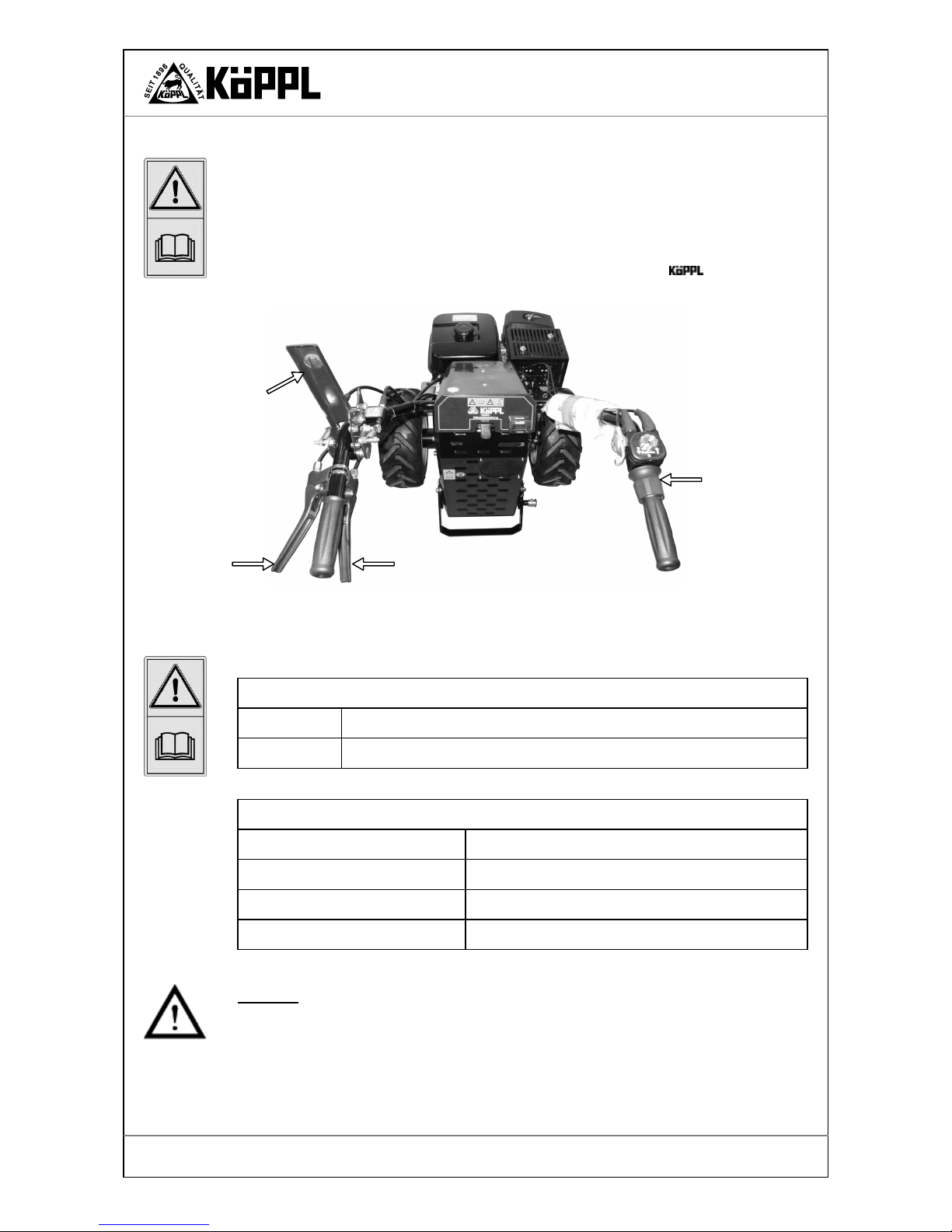
8. Active steering
For easy, agile working, an infinitely controllable hydraulic traction drive is installed in conjunction with active steering. A further advantage of this design is that a hydraulic differential lock is
active when driving straight ahead. With the twist-grip (see fig. 13) you can select your speed infinitely without bothersome gear changes.
When steering you only need to actuate lever A or B. The wheel speed is reduced, depending on how strongly the lever is pulled. Therefore you can move your Compact-Light
without effort in almost any terrain.
How to shift:
Twist-grip
Forwards
Turn twist-grip slowly clockwise.
Reverse
Turn twist-grip slowly anticlockwise.
How to steer with active steering:
Steering lever
To steer to the left
- Lever A pull slightly *
To turn left while stationary
- Lever A pull fully
To steer to the right
- Lever B pull slightly *
To turn right while stationary
- Lever B pull fully
* always pull as required until the machine reacts
Caution!
If the engine is still running and the power take-off is engaged, the attached device will continue
to be driven with the clutch/safety stop lever depressed!!
The two steering levers A and B must be actuated separately when steering.
Fig. 13. Twist-grip, steering levers A und B.
Clutch/safety stop lever
Steering lever A
Steering lever B
Twist-grip
Page 27
Version 02-2012
Operation
Compact-Light
The Compact-Light stops moving when twist-grip is in the 0 position (see fig. 8 – page
22) or when the clutch/safety stop lever (engine drive) is released – the hydraulic traction drive is
interrupted.
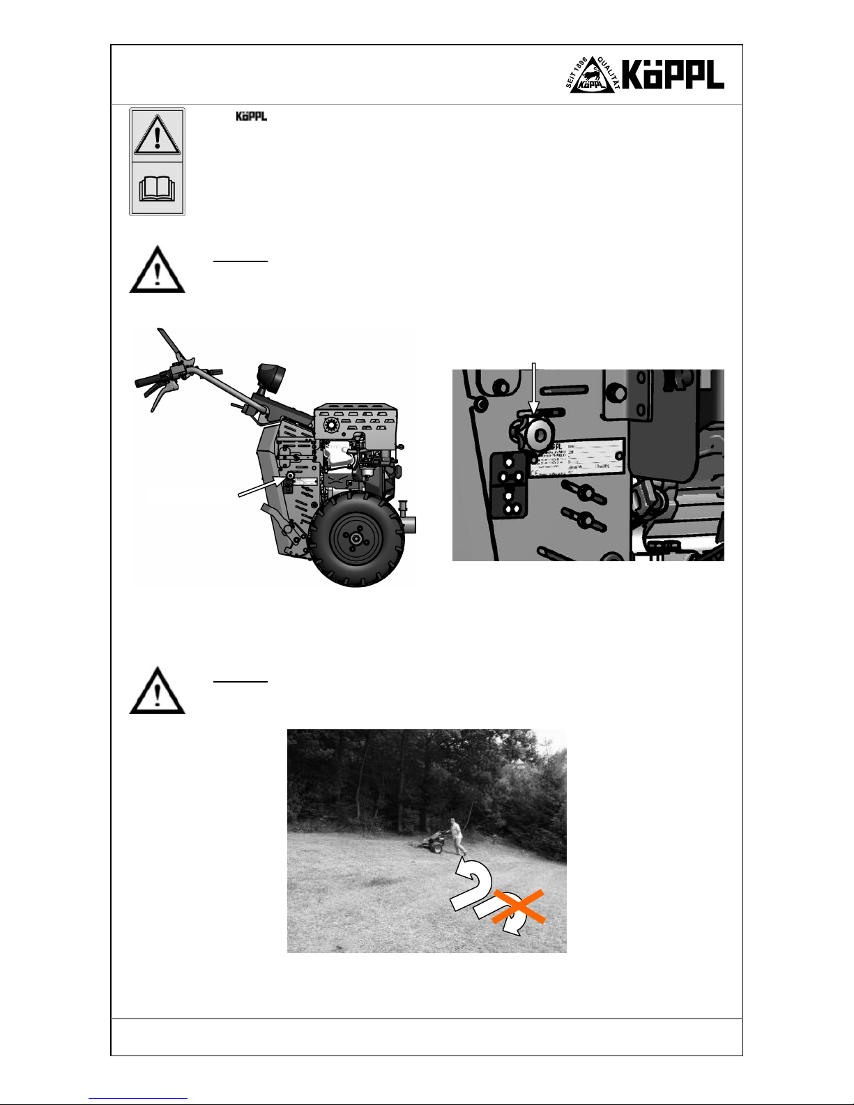
In case of failure of the hydraulics or the engine, the appliance can be pushed by opening the
locking valve. The locking valve is located on the left on the chassis.
Turn the unlocking screw anticlockwise to open the valve – pushing operation.
Turn the unlocking screw clockwise to close the valve – normal operation.
Caution!
Note that the appliance can run away uncontrolled on a slope if the locking valve is open! Check
during operation that the unlocking screw is closed, otherwise there is a danger of the hydraulic
system overheating, which can result in damage to the hydraulic system!
Working with attached devices on a slope
Caution!
When working on a slope, bear in mind that you may only turn in an uphill direction!
Pull the appropriate lever.
Fig. 15. Turning on a slope.
Unlocking screw
Fig. 14. Unlocking screw.
Unlocking screw

Page 28
Version 02-2012
Operation
Compact-Light
9. Rapid-change device flange
A rapid-change flange is fitted for the fast and simple exchange of the attached devices. You can
attach and detach the desired attached devices without tools using the locking pin.
The mating surfaces of the rapid-change flange on the basic device and on the attached device
must be clean; they must be cleaned if necessary.
The mating surfaces must be greased on the inside with special long-life grease (see appendix).
Fig. 16. Rapid change flange.
Rapid-change flange
Grease nipple

Page 29
Version 02-2012
Operation
Compact-Light
10. Parking foot
If the basic machine is to be parked without an attached device, you must use the parking foot.
This is attached to the chassis at the bottom and is released and locked with the aid of the latching bolt.
Pull the latching bolt – parking foot can be adjusted. Always make sure that the latching bolt engages properly!
Fig. 18. Basic device in use.
Fig. 17. Basic device parked without attached device.
Parking foot
Parking foot
Latching bolt
Page 30
Version 02-2012
Operation
Compact-Light
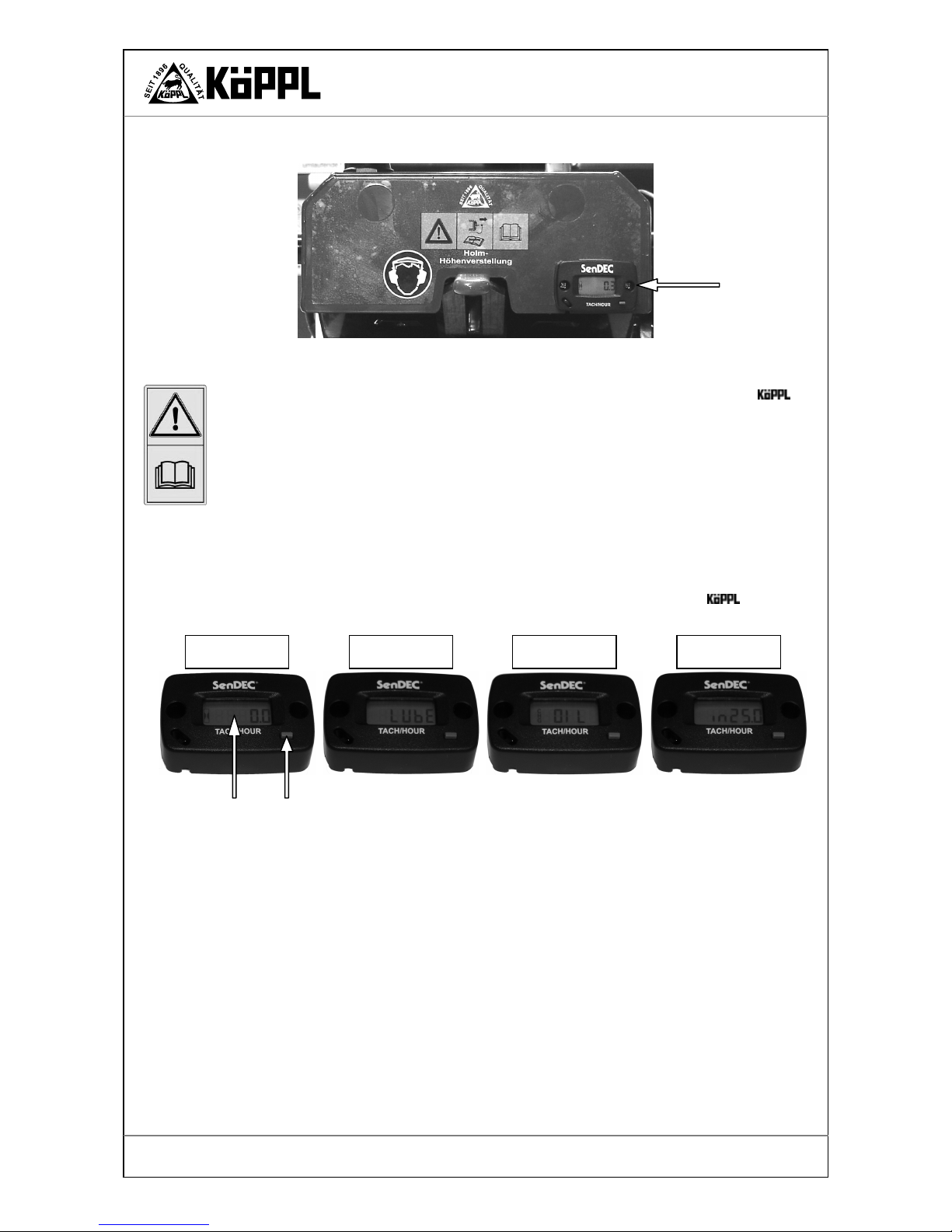
11. Operating hour meter
•
The engine speed is displayed as soon as the engine is started (max. 9,000 rpm,
engines up to max. 4,000 rpm).
•
By briefly pressing the button you can switch between the different display modes.
•
Every 25 hours of operation the displays ‘CHG OIL’ (change oil) and ‘LUBE’ (lubricate) appear.
•
The time remaining until the next interval is indicated by flashing.
•
After the required service has been carried out, the display can be reset to 0 by pressing the button for a longer time (approx. 3 seconds).
THESE INTERVALS ARE PRESET AND CANNOT BE CHANGED!
These settings are not compulsory; please refer to the operating manual for your appliance
for more exact lubrication and oil change intervals!
Operating hour meter
with rev. counter
Fig. 19. Operating hour meter.
Fig. 20. Operating hour meter - display.
Display mode -
operating hours
Display mode -
lubricate
Display mode –
change oil
Display mode –
remaining time

Page 31
Version 02-2012
Maintenance
Compact-Light
Faults
1. Faults and their remedy
Observe the safety instructions!
If faults occur in the tractor or the engine that require a greater degree of intervention, always have them rectified at your specialist workshop, since they have the necessary
tools. Unprofessional intervention can only cause damage.
In order to avoid damage to the machine and life-threatening injuries when rectifying faults on
the machine, it is essential to pay attention to the following points:
•
Rectify faults only if you are in possession of the specified qualifications.
•
First of all, secure the machine against inadvertent rolling away by chocking the wheels.
•
Secure the range of action of the moving machine parts.
•
Also read the chapter ‘General safety instructions’.
Fault
Possible cause
Remedy
Engine
Engine does not start Spark plug cap is not attached.
Choke is not pulled out.
Petrol tap is closed.
Ignition switch is set to ‘OFF’.
Fuel tank is empty or fuel is of a
poor quality.
Fuel line has a blockage.
Spark plug is defective.
Too much fuel in the engine - flooded.
Excess air due to loose carburettor
and suction line.
Fault in the electrical system
Attach the spark plug cap.
Push the choke regulator lever to ON
Open the petrol tap.
Set the ignition switch to ON.
Fill up the fuel tank with fresh fuel.
Clean the fuel line.
Clean, adjust or replace the spark plug.
Dry and clean the spark plug and start
with FULL THROTTLE.
Have the machine checked and repaired
in the workshop.
Appliance
Engine stutters Engine is running in the CHOKE
range.
Ignition cable is loose.
Fuel line has a blockage.
Ventilation aperture in the fuel tank
cap is blocked.
There is water or dirt in the fuel system.
Air filter is dirty.
Carburettor is incorrectly adjusted.
Push the choke regulator lever to the
OFF position.
Push the spark plug cap firmly onto the
spark plug, clamp the ignition cable
tightly.
Clean the fuel line and fill up with fresh
fuel.
Replace the fuel tank cap.
Drain off the fuel and fill up with fresh
fuel.
Clean the air filter.
Have the carburettor adjusted.
Engine runs hot Too little engine oil.
Cooling air system is dirty.
Air filter is dirty.
Carburettor is not adjusted correctly.
Top up the engine oil immediately.
Clean the fan grille, clean the interior
cooling fins.
Clean the air filter.
Have the carburettor adjusted by a work-
shop
.
Engine stutters at high
revs., engine often
stops in neutral
Ignition gap of the spark plug is too
small.
Neutral mixture is not adjusted cor-
Adjust the spark plug.
Have the carburettor adjusted by your

Page 32
Version 02-2012
Maintenance
Compact-Light
Fault
Possible cause
Remedy
rectly.
Ignition gap too large, spark plug de-
fective.
Carburettor is not adjusted correctly.
Air filter is dirty.
workshop.
Adjust the ignition gap and/or replace
the spark plug.
Have the carburettor adjusted by your
workshop.
Clean the air filter.
Engine works irregularly
Regulator linkage is dirty or sticks. Clean the regulator linkage.
Engine doesn’t switch
off in the stop position
Engine stop cable is defective, no
earth.
Check and renew cable and plug connector.
Engine has too little
power
Cylinder head is loose or head gasket
is damaged – too little compression.
Have the engine checked by your
workshop.
Engine in winter operation
Dry air filter iced up Snow dust is being sucked in
Altitude exceeds 1,000 m
Dry or exchange the filter element
Have a larger main jet installed
General
V-belt tensioning lever
has no effect
Tensioning lever is incorrectly adjusted
V-belt is worn.
Cable torn off
Adjust the tensioning lever
Have the V-belt replaced in the workshop
Replace cable.
Hydraulic drive
Excessive noise
Jerky drive movements
(pressure fluctuates)
Fluid level is too low.
Liquid is dirty or foamy
System has not been fully bled
Top up the oil
Exchange the oil
Bleed the system
Wheel drive no longer
pulls
Tensioning lever is incorrectly adjusted
V-belt is worn.
Adjust the tensioning lever
Have the V-belt replaced in the workshop
Foaming of the hydraulic fluid
Suction line is leaking
Oil level is too low
Seals are defective
Seal the suction line
Top up the oil
Have the seals replaced
Drive wheels pull unevenly
Incorrect tyre pressures,
Steering lever incorrectly adjusted.
If this is not actuated, it must be free.
Steering piston sticking.
Check tyre pressures, correct if necessary,
adjust via Bowden cable,
replace steering piston
Hydraulic system has
little power or becomes
too hot
Unlocking screw is not closed. Tighten the unlocking screw firmly in a
clockwise direction.

Page 33
Version 02-2012
Maintenance
Compact-Light
Maintenance
Besides complying with operating regulations applicable to the 2-wheel tractor, it is equally
important to pay due attention to the following instructions for care and maintenance!
Caution!
•
Care and maintenance work may only be carried out when the engine is switched off and the
spark plug cap has been pulled off!
•
Always change the oil in the hydraulic drive and engine promptly.
•
Fluids escaping under high pressure (fuel, hydraulic oil) can penetrate the skin and cause serious injuries. Therefore consult a doctor immediately - risk of infection!
•
Dispose of oils, fuels, batteries, brake fluids, coolants and filters separately and properly!
•
The fitting of tyres requires sufficient knowledge and correct fitting tools!
•
Tighten the wheel nuts again after 8 hours of operation.
•
Always disconnect the earth strap from the battery when working on the electrical system!
•
Spare parts must correspond at least to the technical requirements specified by the manufacturer! This is ensured, for example, by the use of original spare parts!
1. Hydraulic drive
Caution!
•
The hydraulic system is under high pressure!
•
Due to the risk of injury, use suitable aids when searching for leaks!
•
It is essential to switch the engine off and to secure the tractor against rolling away when
working on the hydraulic system!
•
Ensure absolute cleanliness when working on the hydraulic system!
•
Dirt and moisture must not be allowed to get into the system.
•
Open connections should always be sealed with a protective cap, even if only opened for a
short time.
•
Check hydraulic hoses at regular intervals for damage and aging and replace them if necessary!
•
Damaged pipes and hoses must be replaced immediately!
General instructions for working on hydraulic systems
For reasons of safety, hose and pipe joints, connections and devices may not be loosened
when the system is under pressure.
The engine must be switched off beforehand in order to relieve the pressure. The oil and oil
container will be very hot if the machine has been in operation for a longer period of time
before maintenance!!
Before undoing screw connections, the surrounding area must be cleaned. Steel wool may
not be used for cleaning. It is advisable to flush the pipe system thoroughly after assembly.
All openings must be sealed with protective caps. Remove these only immediately before attaching the appropriate pipe or hose.
Fill the system with the prescribed or a suitable hydraulic fluid. The correct hydraulic fluid, and in particular its viscosity, is decisive for the trouble-free operation of the system.
Check the hydraulic fluid for the ingress of water.

Page 34
Version 02-2012
Maintenance
Compact-Light
Check the hose and pipe connections regularly for leaks and tighten them. Screw connections may be tightened only when the system is depressurised. Defective pipes and hoses
must be replaced immediately.
Information
The hydraulic drive is structurally suitable for
long, trouble-free operation. It requires little
maintenance. This is indispensable, however,
since experience shows that up to 80% of the
all occurring faults can be attributed to dirt,
poor maintenance and the wrong oil selection.
Checking the oil level
Check the level each time before putting into
operation and after every 8 hours of operation.
Remove the steering shaft cover and carefully
open the bleed screw. The oil must be at the
marking on the dipstick with the 2-wheel tractor in a horizontal position. The oil level should
not fall below the minimum level marked on
the dipstick. Top up the oil if necessary and
firmly tighten the bleed screw.
Changing the oil
The oil and oil filter must be exchanged every six months or yearly depending on the operating conditions. The service should be carried by an authorised workshop.
•
Allow the drive to run for a short while before changing the oil, so that the warm oil can
drain out more easily.
•
Remove the steering shaft cover and the cover plate at the rear.
•
Remove the oil bleed screw (fig. 21).
•
You need an oil collecting vessel.
•
Unscrew the oil drain plug - fig. 22. Caution – the oil can be hot!
•
Drain off the oil into the oil collecting vessel.
•
Screw the oil drain plug in again firmly.
•
Unscrew the oil filter housing cover – 3 screws.
•
Exchange the oil filter element and the seal, if this is damaged. The front seal must be inserted carefully!
•
Screw the oil filter housing on again firmly.
•
Carefully pour in the oil (approx. 1.9 litres Mobil DTE 10 Excel 68) through the oil filler
neck.
•
Screw the oil bleed screw back on.
•
Start and let the oil pump run for a short time.
•
Check the oil level on the dipstick again.
•
Attach the steering shaft cover and the cover plate at the rear.
Fig. 21. Checking the oil.
Bleed screw with oil dipstick
Marking

Page 35
Version 02-2012
Maintenance
Compact-Light
Important!
Protect the environment:
The handling and disposal of mineral oils are subject to legal regulations.
Take used oil to an authorised collection point.
Do not spill engine oil!
Take precautions to catch spilt oil – lay out an oilproof tarpaulin and use an oil collecting
pan.
Fig. 22. Changing the oil in the hydraulic drive
Oil bleed screw
Oil tank
Seal
Drain plug
Oil filter housing cover
Oil filter housing
Oil filler neck
Seal
Screw
Oil filter insert

Page 36
Version 02-2012
Maintenance
Compact-Light
2. Power take-off drive
Never reach into the crushing danger zone if parts can still move there.
The power take-off drive of the 2-wheel tractor should never be cleaned with water or
a high-pressure water jet cleaner. Dry cleaning is best.
The power-takeoff is driven by one or two V-belts, depending on the engine. These are very robust and only need to be exchanged if they are defective. The repair should be carried by an authorised workshop.
The correct tension can be adjusted on the V-belt tensioning lever. If the V-belt slips or no longer
grips, the tension can be adjusted using the adjusting screw – see also under point 3 Wheel drive.
You must unscrew the adjusting screw until the power take-off works properly again.
If the adjustment is unsuccessful, you must take the machine to an authorised workshop.
3. Wheel drive
Warning!
Secure the tractor against rolling away!
It causes crushing injuries.
Never reach into the crushing danger zone if parts can still move there.
The wheel drive is driven by a V-belt. These are very robust and only need to be exchanged if
they are defective. The repair should be carried by an authorised workshop. Each V-belt
should be inspected after ½ hour and adjusted if necessary.
Tensioning the V-belt
Please note that new V-belts must first be run in and therefore is it necessary to readjust them following a short period of use.
To re-tension the V-belt:
•
Switch off the engine – place the ignition switch in the ‘OFF’ position, remove the ignition
key (if there is one) or pull off the spark plug cap.
•
Secure the tractor against rolling away.
•
Measure the length of the relaxed tension spring on the Bowden cable of the wheel drive.
•
Now depress the tensioning lever and measure the length of the stretched tension spring (see fig. 23).
Tensioning lever for v-belt
- PTO drive -
Adjusting screw
Bowden cable
Fig. 23. PTO lever – adjusting screw with lock nut.
Tension spring
Lock nut

Page 37
Version 02-2012
Maintenance
Compact-Light
•
The difference in length between the relaxed and the stretched tension spring should be 5 - 8
mm.
•
If this is not the case, you must change this distance with the help of the adjusting screw.
•
Loosen the lock nut of the appropriate adjusting screw and turn it until the length of the tension spring is correct. The lock nut must be tightened again afterwards.
The correct tension can be adjusted on the wheel drive tensioning lever. If the V-belt slips or no
longer grips, the tension can be adjusted using the adjusting screw. You must unscrew the adjusting screw until the wheel drive works properly again.
If the adjustment is unsuccessful, you must take the machine to an authorised workshop.
Fig. 24. Tensioning lever. Fig. 25. PTO drive – tension spring.
Tensioning lever
- OFF position -
Tension spring relaxed
Adjusting screw
Wheel drive
Bowden cable
Lock nut
Tensioning lever
- ON position -
Tension spring taut
L + 5 to 8 mm
L

Page 38
Version 02-2012
Maintenance
Compact-Light
4. Engine
Caution!
During the first 20 hours of operation (the running-in period) the engine should not be operated
up to its performance limit. The same basic principle also applies after the running-in period:
The throttle should never be applied more than is absolutely necessary for carrying out the respective work.
Work in an environmentally-friendly, fuel-saving manner!
Caution!
High engine speeds can damage any engine and significantly shorten its service life. This particularly applies to no-load operation! Over-revving the engine can even lead to immediate damage.
The engine is cooled by a fan. The cooling fins of the cylinder should therefore always be kept
free of dirt and any vegetation that has been drawn in.
Information!
When operating the 2-wheel tractor in winter (snow hoeing), it is a good idea to remove the
air filter element – the filter element is part of the scope of supply. For all other work it is essential that the air filter element be installed again.
Refer to the engine manufacturer's operating instructions!
Caution!
It is essential to pay attention to the engine manufacturer’s operating manual.
•
Do not leave the engine running in a closed room – danger of poisoning!
•
Always close the petrol tap when the machine is parked and during transport and repairs.
•
Do not carry out any maintenance with the engine running!
•
Secure the parked 2-wheel tractor against rolling away and tipping over!
•
Refuel only with the engine switched off – no smoking!
•
Pay attention to the prescribed quality of oil and fuel and store both only in approved containers!
•
Caution when draining off hot oil – danger of being burnt!
•
Attach the safety devices again after maintenance work!
5. Drive wheels, wheel motors
Warning!
Secure the tractor against rolling away!
It causes crushing injuries.
Replace the driving wheels only if the engine is switched off and the machine is at a standstill!
•
The tyre pressures must be checked regularly.
•
In particular, it must be ensured that the tyre pressures of both wheels are equal in order to
guarantee effortless driving.
•
In the case of new wheels or a new tractor, the wheel bolts or nuts must be checked after the
first two hours of operation and if necessary retightened to 100 Nm. Otherwise always during service work.
•
The fitting of tyres requires sufficient knowledge and correct fitting tools!
•
Mount the wheels with the tread arrows pointing in the driving direction (as seen from
above the wheels); this produces the full traction power.
•
Check the wheel motor bolts for tightness after the first 10 hours of operation and then after
every 8 hours of operation.

Page 39
Version 02-2012
Maintenance
Compact-Light
6. Attached devices
In the case of attached devices not covered by this operating manual, the instructions that came
with the respective attached device must be followed.
7. General
Watch out for fuel and oil leaks and eliminate them if necessary.
Check the tightness of screws, nuts and bolts regularly and retighten them if necessary.
Lubricate all sliding and moving parts (e.g. shifter linkage, Bowden cables etc.) with grease or
oil, especially after cleaning with a high-pressure water jet cleaner!
8. Safekeeping and storage
Do not park the 2-wheel tractor in damp rooms, in rooms in which artificial fertilisers are
stored, in stables or in adjacent rooms, since this will cause lead to severe corrosion.
If the 2-wheel tractor is not to be used for a longer period of time:
•
clean the machine thoroughly, repair any paint damage and spray bare parts with anticorrosive oil.
•
Close the petrol tap if the machine is left to stand for longer periods of time.
•
Jack up the driving wheels so that the tyres are not resting on the ground. Pneumatic tyres
become unusable in a very short space of time if they are left under load without air in them.

Page 40
Version 02-2012
Maintenance
Compact-Light
9. Maintenance schedule
Inspection and maintenance overview
P S
8
[h]
25
[h]
50
[h]
100
[h]
at least
annually
C Page
Safety stop lever
Function check
O 13 / 33
Lubricate all sliding parts
O O
Cleaning
O O
Check hydraulic pipes,
hoses
O O O O
Check oil level in
hydraulic drive
1
O O O 31
Change oil and oil filter in
the hydraulic drive
For the first time
Then every
if alternative oil is used every
2
W
W
W
W
W
31
Lubricate the rapid-change
flange
3
O O O O 26
Check/tighten screws, bolts
and operating parts
O O O
Check and lubricate shift
levers
4
O O O O
Check, lubricate and adjust
Bowden cables
5
O O O
Tyre pressures
O O O 17
Engine maintenance: refer to the respective engine manufacturer’s operating manual
P = Position
S = before each start-up
O = checking and care work that can be carried out by operator
W = have the maintenance work carried out by a specialist workshop
C = after each cleaning, especially with a high-pressure cleaner
Page = Page in the operating manual
V/8
h
P 3
100 h
P 2
V/8 h
P 5
V/8 h
P 4
V/8 h
P 1
Page 41
Version 02-2012
Edition / Revision
Compact-Light
Appendix
1. Lubricants / adhesives
Use the prescribed lubricants for the engine and drive (see ‘Technical data’).
We recommend the use of anti-corrosion agents to conserve the 2-wheel tractor. Do not use
these on painted outer claddings. Anti-corrosion agents can be applied using a brush or a spray
device.
When applying adhesives (for the locking of screws) and sealing compounds, both adhesive and
sealing surfaces must be clean and free of grease.
Please read the note included in the package and take note of the manufacturer’s safety instructions!
Order number Lubricants Size
EP2
SP-MO
SP-HY-03
Special long-life grease (lead-free, long-life grease
with EP properties), for rapid change flange
Engine oil: SAE 15W-40
Hyd. system: Mobil DTE 10 Excel 68
400 g cartridge
1 litre bottle
1 litre bottle
Order number Anti-corrosion agent Size
028770
SW400
Rust remover
Protective wax
300 ml can
400 ml can
Order number Size

Page 42
Version 02-2012
Maintenance
Compact-Light
EU Conformity Declaration
The manufacturer:
Made in Germany
declares that the machine described on the
right:
-2- wheel tractor
Type:
CL10-2
CL13-2 SNOW
CL14-2
complies with the health and safety requirements contained in the following EU directives:
EU machine directive 2006/42/EC
Harmonised standards applied:
EN ISO 12100-1, EN ISO 12100-2, EN 12733,
EN ISO 13857, EN ISO 14121-1, EN 349, EN 709
National standards and technical specifications
applied:
Structural changes that affect the technical data specified in the operating manual and the
appropriate use of the machine, i.e. changes that significantly alter the machine, will render this declaration of conformity invalid!
Entschenreuth, 21.11.12 __________________________________________
Managing Director
Köppl, Karl senior
 Loading...