

M O TOR G ER Ä T E F A BR I K
94163 ENTSCHENREUTH
(0 99 07) 89 10-0 ɀ Fax (0 99 07) 10 42
Internet: http://www.koeppl.com
email: info@koeppl.com
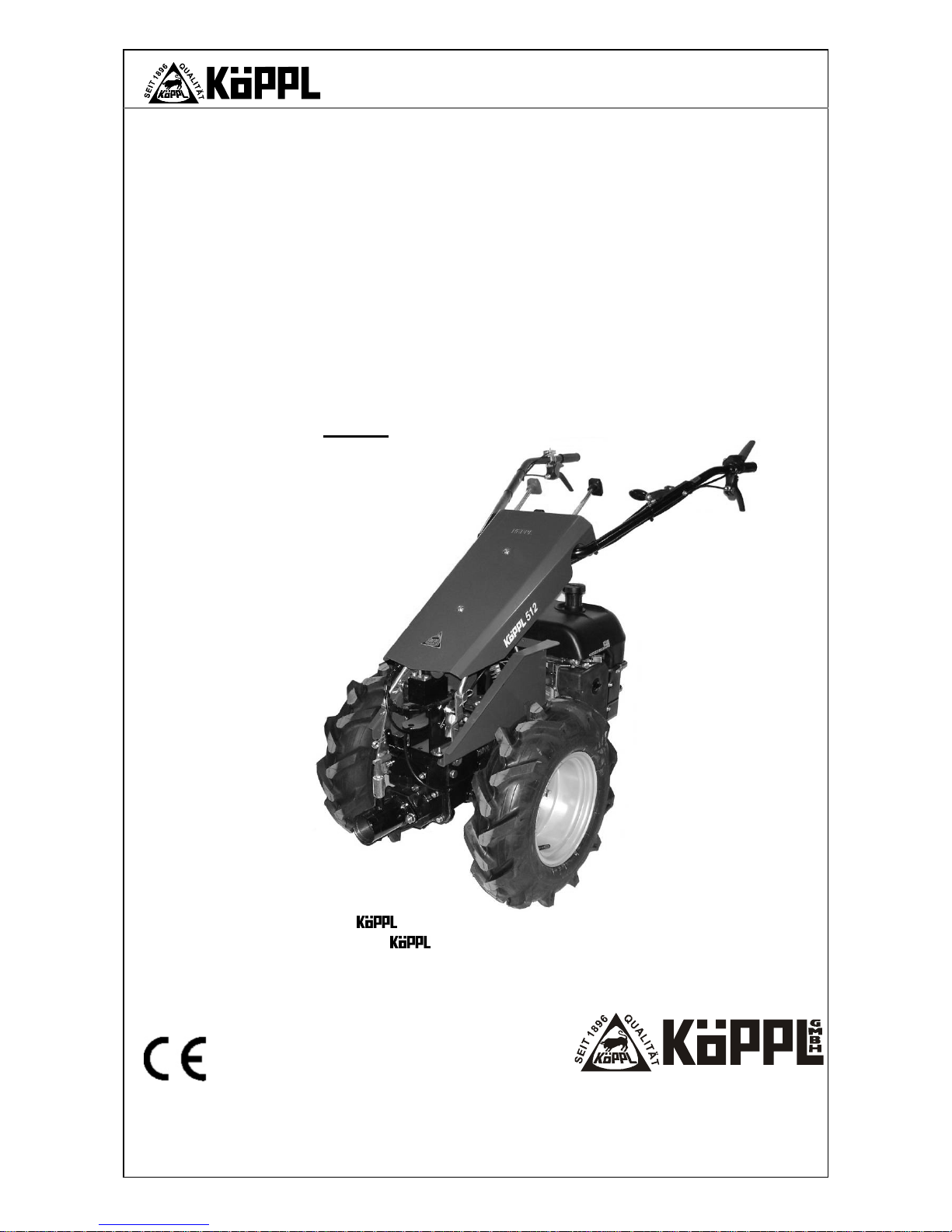
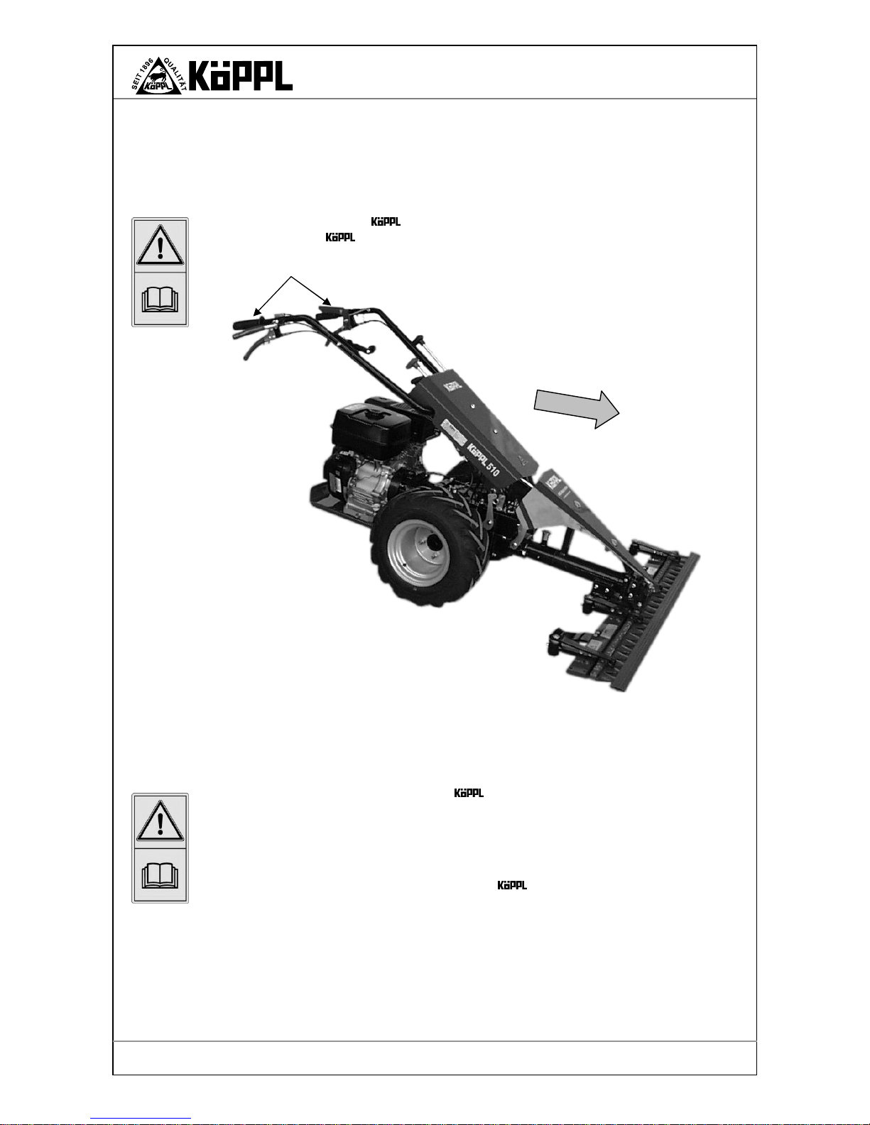
Operator manual
for
2-wheel tractor
Series 500
The basis for working with the 2-
wheel tractor is that you read, observe and understand this
operator manual of the utilized accessory equipment and the engine manufacturer.
You may not begin operation before doing so.
Beginning work without observing this manual is prohibited!
Edition / Rev.
- Date
01-2009 ☺ 11/18/09
Store for future usage!
Types 4H 500, 4K 500, 4M 500

N
OTES
Page 2
Version 01-2009
S500K
Translation of the original operator manual

P
REFACE
Page 3
Version 01-2009
S500K
Preface
Before commissioning the
2-wheel tractor it is absolutely necessary to read
and observe the proper usage and the safety notes!
The guarantee is ensured only for proper operation!
Valued customer! You have made the right decision!
Although the selection is great, you have chosen a
2-wheel tractor.
That pleases us greatly. We will make an effort to keep you satisfied over the years.
As of now, you will hopefully be our best advertiser.
The following points distinguish our product:
- The machine is very stable, one can work effortlessly.
- It is equipped with an outstanding engine.
- The maintenance costs are thus very low.
- The gear shift is easy to operate.
- The spare parts supply is guaranteed and occurs quickly.
- An optimal customer service is available to you at all times.
The
2-wheel tractor has resulted from decades of experience and can therefore be
placed into continuous practice.
is constantly working on advancements of machines and devices. We must
therefore reserve the right to make changes to the scope of delivery in form, technology and equipment. Please understand that no claims can be made based on
statements and illustrations in this manual.
LET US KNOW YOUR SUGGESTIONS FOR IMPROVEMENT!

T
ABLE OF CONTENTS
Page 4
Version 01-2009
S500K
Table of contents
PREFACE ........................................................................................................................................... 3
TABLE OF CONTENTS ......................................................................................................................... 4
PROPER USAGE ................................................................................................................................. 5
1
GENERAL SAFETY NOTES ................................................................................................... 6
1.1 Possible hazards during interaction with the 2-wheel tractor.................................................. 6
1.2 Safety notes and hints ............................................................................................................. 6
1.3 Hazards due to accessories ....................................................................................................... 7
1.4 Emissions ............................................................................................................................... 8
1.5 Hazard sources ....................................................................................................................... 9
1.6 Lighting devices on single-axle tractors ....................................................................................... 9
1.7 Workplace ............................................................................................................................ 10
1.8 Authorized operators ............................................................................................................. 10
1.9 Personal protective equipment ................................................................................................ 11
1.10 Safety measures at the work site ............................................................................................. 11
1.11 Protective devices ................................................................................................................. 12
1.12 Leaving the tractor ................................................................................................................ 13
1.13 Safety tool attachments ......................................................................................................... 13
2
TRANSPORT ...................................................................................................................... 14
2.1 Tractor size / machine dimensions ........................................................................................... 14
2.2 Technical data ...................................................................................................................... 15
3
OPERATION ...................................................................................................................... 16
3.1 Commissioning...................................................................................................................... 16
3.2 Starting ............................................................................................................................... 16
3.3 Switching gears in general ...................................................................................................... 17
3.4 Gear switching - steering shaft ................................................................................................ 17
3.5 Shifting – fixed shaft .............................................................................................................. 19
3.6 Shifting – forward/ reverse gear on the shaft ............................................................................ 20
3.7 Clutch .................................................................................................................................. 20
3.8 Power take-off ...................................................................................................................... 21
3.9 Differential gears ................................................................................................................... 22
3.10 Engine ................................................................................................................................. 23
3.11 Gas pedal ............................................................................................................................. 23
3.12 Shaft adjustment ................................................................................................................... 24
3.13 Steering shaft - optionally / for Type 4M standard ...................................................................... 24
3.14 Parking brake / brake - optional .............................................................................................. 26
3.15 Device connection ................................................................................................................. 27
4
MALFUNCTIONS ................................................................................................................ 29
4.1 Malfunctions and their remedy ................................................................................................ 29
5
MAINTENANCE.................................................................................................................. 31
5.1 Maintenance plan .................................................................................................................. 31
5.2 Engine ................................................................................................................................. 32
5.3 Gear box .............................................................................................................................. 32
5.4 Driving wheels ...................................................................................................................... 33
5.5 Steering shaft ....................................................................................................................... 33
5.6 General ................................................................................................................................ 33
5.7 33
5.7 Tool attachments .................................................................................................................. 34
5.8 Safe-keeping and storage ....................................................................................................... 34
6
APPENDIX ......................................................................................................................... 35
6.1 Lubricants / adhesives ........................................................................................................... 35
6.2 Accessories .......................................................................................................................... 35
EU DECLARATION OF CONFORMITY ................................................................................................ 36
Page 5
Version 01-2009
S500K
P
ROPER USAGE
Proper usage
The -2-wheel tractors (Type 4H 500 / 4K 500 / 4M 500) as well as the original at-
tachment equipment approved by the manufacturer are exclusively constructed for the usual usage and work in agriculture and forestry, such as grass and field mowing. This can also include
snow removal, winter work and sweeping.
The 2-wheel tractor is depending on the shaft position designed for the following work:
Front attachment: For mowing, rotation ploughing, chaffing, soil drilling, cleaning, snow
blowing, snow removal, transport.
only with steering shaft
Hedge construction: Rotary tilling, ploughing, grubbing, one axled trailer (brakes required).
• The conditions set down in the offer and in the "proper usage" are decisive. Every usage ex-
tending beyond this is not proper usage. The manufacturer assumes no liability for damages
resulting from this; the risk is borne solely by the user.
• This work is only allowed in appropriate scope of the engine size, wheel size and relation-
ship of the surroundings.
• The -2-wheel tractor (Type 4H 500 / 4K 500 / 4M 500) may only be used, main-
tained and repaired by persons who are familiar with this and have been instructed about
the hazards.
• The 2-wheel tractor may not be used on strongly sloping territory. For these special
usages there are tool attachments, twin wheels, iron hanging wheels, track widening, etc.
• Unauthorized changes to the construction of the 2-wheel tractor are prohibited for
reasons of safety!
• The relevant accident prevention directives as well as the other general safety, occupational
health, and traffic rules must be complied with.
Important!
The operating and maintenance conditions prescribed in this operator manual for the
2-wheel tractor are the conditions for the proper usage and must be strictly complied
with.
Warning!
Should the machine be used for a purpose other then the intended purpose listed above or
driven at powers greater than allowed, hazardous situations for persons can result or material damages occur.
Information!
Improper and prohibited use of the machine are not recognized by the manufacturer. Improper attachment of auxiliary devices and parts, which have not been obtained from
exclude any liability for damages resulting from this.

G
ENERAL SAFETY NOTES
Page 6
Version 01-2009
S500K
1 General safety notes
1.1 Possible hazards during interaction with the 2-wheel tractor
In the case of improper usage or misuse hazards threaten for
• the life and limb of the operator,
• of the
2-wheel tractor and other property of the operator,
• the efficient work of the -2 -wheel tractor
All persons involved with the commissioning, operation, and maintenance of the -2-wheel
tractor must:
• be accordingly qualified
• observe and follow this operator manual precisely!
It is a matter of your safety!
1.2 Safety notes and hints
The following symbols are used in this operator manual:
Warning!
Points out important safety hints in this operator manual.
When you see this symbol, be aware of possible risks of injury. Read the following note carefully and inform the other operators.
Caution!
Indicates a possibly dangerous situation.
Nonobservance of this note could lead to light injuries.
Information!
Indicates safety tips and other useful information.
Wear protective
glasses
Wear protective
gloves
Wear safety shoes
Wear hearing prote
c-
tion
Before repair, mainte-
nance and cleaning
work, turn off the engine
and remove the spark
plug connector!
Before commissioning,
read and observe the
operator manual and
safety notes!
Page 7
Version 01-2009
G
ENERAL SAFETY NOTES
S500K
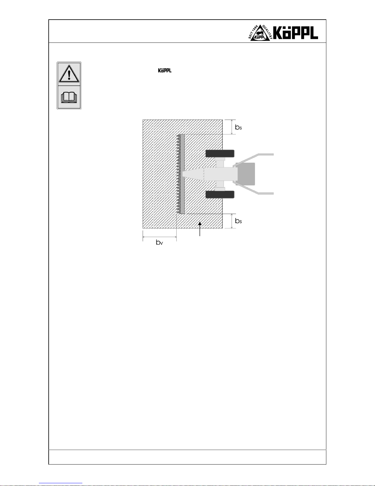
1.3 Hazards due to accessories
Tool attachments, mowing devices and other utilized auxiliary devices may not deactivate the
protective equipment of the
-
2-wheel tractor.
Standing in the hazard zone during work is prohibited.
This zone begins in the middle of the wheel axle, reaches laterally and forwards - depending on
attachment - to various distances:
with
- Mowing beam b
s
= 1 m bv = 2 m
- Snow removal sign bs = 0.5 m bv = 2 m
- AZM-S b
s
= 2 m bv = 5 m
- AZM-A bs = 25 m bv = 25 m
- Sweeping machine bs = 2 m bv = 5 m
- Snow blower bs = 25 m bv = 25 m
- Rotary tiller bs = 2 m bv = 5 m
Also observe the operator manuals of the respective implements!
Hazard zone

Page 8
Version 01-2009
S500K
G
ENERAL SAFETY NOTES
1.4 Emissions
1. Noise information (Sound power level EN ISO 3744, noise pressure level EN ISO 11201)
The A-rated sound power and A-rated Emission-noise pressure level of the
-2-wheel tractor
is at the ear of the operator without auxiliary devices
Design
Sound power level
[dB (A)]/[ rpm]
Noise pressure level
[dB (A)]/[ rpm]
Vibrations
[m/s²]
506 97.3 84.0 2.5
510 98.8 84.7 3.6
512 98.1 86.5 3.7
505H 102.7 93.4 3.9
508H 104.2 92.5 4.2
512H 103.5 90.1 4.6
Depending on the attachment, an increased noise pressure level from up to 4.5 dB(A) can be expected - wear hearing protection!
• The measurement is made on the lawn outdoors; Based on EN ISO 3744 (sound power lev-
el) and EN ISO 11201 (noise pressure level).
• The measurement device used, Norsonic Type 116, conforms to the standard DIN IEC 651
- class 1, DIN IEC 804 - class 1, DIN 45657 - class 1.
• Engine speed = highest engine operating speed
• Radius of the half-shaped measurement surface = 4 m.
2. Vibrations - measurements taken in accordance with EN 1033
Measurement device
• Measurement device - CASTEL, GA-2003
• Vibration pickup - MONITRAN LTD, MTN / P100T-10, S/N 203988
Operating conditions
• Fuel filled approx. 50%.
• Steering shaft set to the body size of the operator.
• Machine broken in and warmed up.
• Measured on the steering shaft in accordance with EN 12733.
• Engine speed = highest engine operation speed
Page 9
Version 01-2009
G
ENERAL SAFETY NOTES
S500K
1.5 Hazard sources
The -2-wheel tractor may be used on commercial and well as private plots.
• Before every start-up, check the machine for traffic and operational safety!
• In addition to the information in this operator manual, observe the general safety and acci-
dent prevention directives!
• During usage of the
-2-wheel tractor on public traffic routes (streets) the directives of
the street traffic ordinance apply in its most recent version. (For this also see 1.6)
• Before beginning work, you must be familiar with all equipment and actuating elements
and their functions. Make certain that all protective devices are properly installed!
• The user is responsible to third parties in the work area!
• Standing in the work and hazard zones of the -2-wheel tractor is prohibited!
• Before starting to drive, check the surrounding area - children! Ensure sufficient visibility!
• Do not let engine run in closed rooms!
• The driver's clothing should be close-fitting. Avoid wearing loose clothing. Wear firm
shoes!
• Caution is recommended when working with fuel - increased risk of fire! Never refuel in
the vicinity of open flames, ignitable sparks and hot engine parts. Do not smoke when fueling!
• Before fueling, switch off the engine and pull out the ignition key (if present). Do not refuel
in closed rooms. Do not spill fuel! Use suitable filling aids.
• To avoid risk of fire, keep the main engine clean!
• Before maintenance and cleaning work, turn off the engine and remove the spark plug
connector!
• When coupling and decoupling tool attachments to or from the main engine, particu-
lar caution is necessary!
• Make certain that all protective devices are properly installed!
1.6 Lighting devices on single-axle tractors
Here one must differentiate whether the one axled tractor
• is guided by a pedestrian on the shafts,
• is driven from a seat cart (single-track trailer) or
• driven from a trailer.
One axled tractors, which are guided by a pedestrian on the shafts, require during darkness - or
when the weather requires – at least one simple lamp with white light, which should be attached
to the left side or carried along manually, so that the light is well visible to oncoming and passing traffic (§ 50 Para. 2 of the Road traffic act and § 17 Para. 5 of the Road traffic act).
One axled tractors which are driven from a seat cart or a trailer
• must be equipped up to a width of 1000 mm with one headlight,
• beyond a width of 1000 mm with two headlights
, which when pulling a one axled trailer can be fastened to this (§ 50 Para. 2 of the Road traffic
act).
If the one axled tractor is driven from a single-track seat cart, then a triangular reflector and a
taillight must be attached (§ 53 Para. 6 of the Road traffic act), blinking lights (travel direction
indicator) are not required for a seat cart. (§ 54 Para. 5 No. 5 of the Road traffic act).
For one axled tensile or work machines, which are operated by a walk-behind person, no operating permit or driver's license is required.
During transport of a one axled tractor with trailer on public streets, which is used for lof purposes, the operating permit is sufficient up to a design-related maximum speed of 20 km/h. It
Page 10
Version 01-2009
S500K
G
ENERAL SAFETY NOTES
must be guided along. The name and domicile of the holder must be indicated by a sign on the
trailer. A class L driver's license is sufficient. A permit is required for design-related speeds over
20 km/h..
1.7 Workplace
The operator position on the
-2-wheel tractor is found on both steering shafts (operator
field) in front of the -2-wheel tractor
1.8 Authorized operators
Only authorized persons may work with the -2-wheel tractor.
The minimum age for operators is 16 years.
The operator is responsible to third parties in the work area.
The responsibilities for the various activities on the
-2-wheel tractor must be clearly de-
termined and maintained. Unclear competencies are a safety risk.
The operating company must
• make the operator manual available to the operator
• and make certain that the operator has read and understood it.
Operator position
Travel direction
Figure 1. Operator position.

Page 11
Version 01-2009
G
ENERAL SAFETY NOTES
S500K
1.9 Personal protective equipment
For the operation
Wear firm shoes!
Wear close-fitting clothing
For longer work times, suitable hearing protection should be worn.
For the cleaning
Firm protective gloves (leather) for protection against sharp objects
(auxiliary devices).
For sharpening the mowing blade
Wear protective glasses
1.10 Safety measures at the work site
• When starting the engine, the traction drive and gear box must be decoupled.
• Travel, steering, braking as tilt behavior are influenced by tool attachments. There-
fore ensure sufficient steering and braking capability and adapt the work speed to the
environmental conditions!
• When driving on hills, in valleys or across slopes, avoid sudden curves.
• Driving downhill in neutral gear is prohibited! The machine can roll away due to its
own weight!
• When the engine is running, wearers of pace makers may not touch the current-
carrying parts of the ignition system.
• Before starting to drive, check brakes and brake effectiveness.
• Remove larger objects from the work area (e. g. boards, cables, rocks, etc.).
• Keep hands and feet away from moving parts during operation.
• Ensure sufficient lighting in the work area.
• Work cross-wise along the slope, never up or down it!
• Be particularly careful when changing the travel direction on the slope.
• Never decouple and switch gears on inclines.
• Never leave the operator position during the work.
• Never make changes or repairs to load-carrying and safety-related parts (frames, ax-
les, etc.)
• In case of damages, stop the machine immediately. Pull out spark plug connectors on
the main engine and have damages repaired!
• Should the machine be used for cutting fruits, which are considered food, such places
which come into contact with the food may not be lubricated with machine oil or
grease or protected against rust.
• Should risk of slipping exist in sloping territories, then the
- 2-wheel tractor
should be held by an assistant with a rod or rope. The assistant must stand above the
vehicle at a sufficient distance from the work tools.

Page 12
Version 01-2009
S500K
G
ENERAL SAFETY NOTES
1.11 Protective devices
The -2-wheel tractor is equipped with a safety stop lever on the steering shaft (left)
which shuts off the ignition system when released i.e. the engine is stopped - Stop setting, see
figure 3.
Warning!
The engine overtravels due to centrifugal mass!
• During operation of the
-2-wheel tractor the safety stop lever must be pressed
down - operating position.
• The safety stop lever must be pressed when the machine is started, the clutch pulled and
blocked with the interlock - starting up, see figure 2.
• It is prohibited by the
company to leave the safety stop lever in the starting position
(safety stop lever pressed + clutch pulled + interlock latched) if the machine should be
cleaned, have maintenance performed on it or be abandoned - e.g. cleaning the snow blower - the device must be brought to a stop with the safety stop lever before the tool is
cleaned.
• In the case of machines with a cone clutch (505/506) stop the engine after ending the work
and set the clutch to the start position (see figure 2) so that the clutch cannot stick - due to
humidity.
Deactivating the safety stop lever by binding or taping down is prohibited.
The protective devices
Are installed to protect the operators and may not be changed or removed under any circumstances and may not be bypassed by making changes to the -2-wheel tractor.
The safety stop lever serves as an EMERGENCY-OFF SWITCH which should be released in
the case of hazardous situations which require quick deactivation. This then pivots automatically
to the position "STOP".
Bild 2. Safety stop lever - start up setting.
Safety stop lever
Setting Start
Interlock latched Clutch control pulled
- decoupled -
Bild 3. Safety stop lever - stop setting.
Absolutely make certain
of
the clutch clearance
of approx. 10 mm.
Safety stop lever
Setting Stop
Clutch control
Setting screw

Page 13
Version 01-2009
G
ENERAL SAFETY NOTES
S500K
1.12 Leaving the tractor
• Stop the engine, put into gear and select gear ratio, engage parking brake; remove ignition
key (if present).
• Upon leaving the 2-wheel tractor, secure it against rolling away (parking brake,
wheel chock) and unauthorized usage.
• Never leave the
2-wheel tractor unattended while the engine is running.
• During travel, never leave the operator position on the steering shaft.
• When parking the tractor, close the gasoline valve.
1.13 Safety tool attachments
• When coupling and decoupling tool attachments, a risk of injury exists. Particular
caution is recommended!
• Only attach tool attachments when the engine and gear box are shut off.
• Secure
-2-wheel tractor and tool attachments against rolling away (parking brake,
wheel chocks). Attach transport and safety devices and bring into a protected position.
• Couple the tool attachments properly and only attach to the prescribed devices.
• Riding as a passenger during the work and transport trip on the attachment of the
-2-
wheel tractor is prohibited.
• Be aware of allowable axle loads, total weights and transport dimensions!
• Check and install transport equipment (lighting, warning devices, protective devices).
• In case of damages, stop the machine immediately. Remove ignition key if present. Have
damages repaired.
• After the repair work, bring the protective and safety devices back to the protected position.
Only now is operation again allowed.
• Check the protective devices and implements for wear.
• External power-actuated parts (e. g. hydraulics) contain crushing and shear zones.
• Standing in the work, rotary and pivotal area is prohibited!
• Before beginning work, foreign bodies should be removed from the area to be worked on.
During operation, beware of foreign bodies!
• Caution in the case of overtraveling tools! Repair work is only allowed during complete
standstill when the engine is shut off (spark plug connectors pulled out).
• Only work if lighting and visibility are good.
• Caution when working on a slope! During excavation of the
-2-wheel tractor risk of
tipping! Drive crosswise on the slope as much as possible.
• When driving outside of the area to be worked on, the gear box should be disconnected and
the
-2-wheel tractor lifted into the transport position.
• When using a riding car, the
-2-wheel tractor may not be driven (operated) in 4th gear.

Page 14
Version 01-2009
S500K
T
RANSPORT
2 Transport
2.1 Tractor size / machine dimensions
Tires
a
[mm]
c
[mm]
d
[mm]
h
[mm]
l
[mm]
4.00 x 8 377 220 210 1,191 1,415
4.00 x 12 377 280 270 1,241 1,415
5.00 x 10 377 270 260 1,241 1,415
18 x 9.5 x 8 377 230 220 1,211 1,415
21 x 11.00 x 008 377 270 260 1,241 1,415
Figure 4.
-
2-wheel tractor - position for front attachment.
Steering shaft
Forward
Engine
Quick-change flange
h
a
l
c
d

Page 15
Version 01-2009
S500K
T
RANSPORT
2.2 Technical data
Suitability for
4H 500
all work with not too
heavy
auxiliary devices
4K 500
professional work, fast
work-site change
4M 500
Gardening, landscaping,
trailer transport work
Engine in the rear
Number of gears
Work speed
depending on tire size
4 V , 3 R
1 - 12 km/h
4 V , 3 R
1 - 12 km/h
3 V , 3 R
1 - 5 km/h
Engine in front
Number of gears
Work speed
depending on tire size
3 V , 3 R
1 - 5 km/h
3 V , 3 R
1 - 5 km/h
4 V , 3 R
1 - 12 km/h
Power take-off [rpm]
950
at 3,600 rpm
Engine speed
950
at 3,600 rpm.
Engine speed
950
at 3,600 rpm.
Engine speed
Steering shaft
for front and rear tool attachments
as accessory *
as accessory *
standard
fixed shaft
standard
standard
-
approx. weight [kg]
depending on engine type, without tires
77 – 90 120 - 157 77 - 140
Differential with block
-
standard
standard
gear oil
SAE-85 W 90 API
GL 4/5
SAE-85 W 90 API
GL 4/5
SAE-85 W 90 API
GL 4/5
Filling quantity gear oil
approx. 1.7 Ltr. approx. 1.7 Ltr. approx. 1.7 Ltr.
* When using a rotary tiller a steering shaft is required !
Type
Engine
Version 1
Engine
Version 2
505H
Diesel
Hatz
/ 1B 20
3.6 kW
-
508H
Diesel
Hatz / 1B 30
5.6 kW
-
512H
Diesel
Hatz / 1B 40
7.8 kW
-
506
Gasoline
Robin / EH, 17-2D
4.4 kW
-
510
Gasoline
Robin /
EX 270
6.6 kW
ACME /
ACT 280
6.6 kW
512
Gasoline
ACME /
ACT 340
8.2 kW
Tires
Tire type Tire size Pressure
Field bar tires
4.00 x 8
5.00 x 10
4.00 x 12
2.0 bar
Lawn tires
18 x 9.5 x 8
2.0 bar
Low pressure tires
21 x 11.00 x 008
1.5 bar
Wide tires AS
18 x 9.50 x 8 AS
16x 6.50 x8 AS
2.0 bar
Multi-disk tires
Snow tires
4.80 x 8
16 x 6.5 x 8
2.0 bar
Twin tires
with intermediate flange
4.00 x 8
4.00 x 12
5.00 x 10
2.0 bar

Page 16
Version 01-2009
S500K
O
PERATION
3 Operation
In order to avoid machine damages or life-threatening injuries during commissioning of the machine, the following points must be absolutely observed.
You must have read and understood:
• the operator manual according to the engine manufacturer,
• the respective operator manuals for each too1attachment,
• Operator manual for -2-wheel tractor,
• In particular chapter 1, safety and protective devices.
You may not operate the -2-wheel tractor before doing so.
3.1 Commissioning
The following points must be checked before the initial start-up:
• Check of engine oil - see operator manual of the engine manufacturer,
• Check of gear oil,
• Check of all safety devices,
• Check if there is enough fuel in the fuel tank,
• Check all screws and operator parts of the basic and attachment devices for tightness.
• Remove all tools and foreign parts from the machine.
• Set the shaft to body size and intended purpose.
Warning!
Exhaust fumes contain carbon monoxide!
Inhaling causes very serious poisoning which can be fatal.
Important!
During the first 20 operating hours (warm-up time) do not run the engine to the limit of its power
capacity.
After approx. 10 operating hours check all screws and operator parts of the basic and attachment
devices for tightness.
3.2 Starting
Warning!
Activated traction drive and gear box can roll over you and cause serious injuries.
When starting the engine, the traction drive and gear box must be decoupled.
Do not step in the vicinity of the coupled implement.
When starting the tractor, please observe:
Press down the safety start lever with your left hand and pull the clutch. Now you can press
in the interlock with your right hand until it latches - see figure 2, page 12. Please observe
the respective operator manual of the engine manufacturer when starting the engine - start
according to the operator manual of the manufacturer.
When the engine is running, bring the gas lever slowly into the middle position and allow the
engine to warm up briefly. Push the CHOKE-lever slowly back into the operating position - if it
was pulled.
For this, also see the operator manual of the engine manufacturer.
In the case of a diesel engine, the starting device should be followed according to the engine
manufacturer!

Page 17
Version 01-2009
O
PERATION
S500K
3.3 Switching gears in general
Caution!
When switching gears, particularly on a slope, absolutely engage the parking brake before every
switching procedure (gear shift) – place lever in the braking position - see below. Only then, select the desired gear. If you switch gears without the parking brake, it is possible that the machine can roll away.
Carry out the following steps:
• Pull the clutch lever
• Engage parking brake (shaft left)
• Select gear
• Slowly release the parking brake and simultaneously release the clutch (similar to driving a
car).
3.4 Gear switching - steering shaft
Gear switching - front attachment
Caution!
For all gear switching procedures, the clutch must always be pulled first.
B
Figure 6. Gear shift in position - front attachment
Neutral gear mar-
king
LEVER IN
FRONT
Parking brake is
disengaged
LEVER REAR
Parking brake
is
engaged
Figure 5. Parking brake
A
C
Front attach-
Engine in the
Lever 2
Shaft pivoting
Lever 1
Shaft height adjustment

Page 18
Version 01-2009
S500K
O
PERATION
Gear shift designation (see figure 6)
Lever A Gear shift for various work speeds such as neutral gear (black handle on the gear
shift control).
Lever B Gear shift for power take-off drive shaft - Switching on and off (red handle on the
gear shift control).
Lever C Gear shift for forward and reverse travel (black handle on the gear shift control).
Forward and backward travel (work position front attachment)
use lever A to set the desired gear - always pull the clutch first.
use lever C to select the forward or reverse travel direction.
In the process the following types must be distinguished:
For type 4M 500
Forward gear Press lever B forwards.
Reverse gear Pull lever B backwards.
For type 4H 500 / 4K 500
Forward gear Pull lever B backwards.
Reverse gear Press lever B forwards.
Shifting - rear attachment
– only with steering shaft
Caution!
For all gear shifting procedures, the clutch must always be pulled first.
Before a shifting procedure the clutch must always be pulled.
Figure 7. Gear shift in position – rear attachment.
Engine in
Steering shaft
Rear atta-
A
B
C
Lever 2
Shaft pivoting
Lever 1
Shaft height adjustment

Page 19
Version 01-2009
O
PERATION
S500K
Gear shift designation (see figure 7)
Lever A Gear shift for various work speeds such as free travel (black handle on the gear shift
control).
Lever B Gear shift for power take-off drive shaft - Switching on and off (red handle on the
gear shift control).
Lever C Gear shift for forward and reverse travel (black handle on the gear shift control).
Forward and backward travel (work position rear attachment)
use lever A to set the desired gear - always pull the clutch first.
use lever C to select the forward or reverse travel direction.
In the process the following types must be distinguished:
For type 4M 500
Forward gear Pull lever B backwards.
Reverse gear Press lever B forwards.
For type 4H 500 / 4K 500
Forward gear Press lever B forwards.
Reverse gear Pull lever B backwards.
Caution!
The 4th gear may not be used for reverse travel.
Do not in any case remove the safety device installed for this purpose.
3.5 Shifting – fixed shaft
Differential is activated using a lever on the right shaft
Caution!
For all gear shifting procedures, the clutch must always be pulled first.
Gear shift designation (see figure 8)
Lever A Gear shift for various work speeds such as neutral gear (black handle on the gear
shift control).
Lever B Gear shift for power take-off drive shaft - Switching on and off (red handle on the
gear shift control).
A
B
Figure 8. Gear shift fixed shaft.
Neutral gear mar-
king
Lever 1
Shaft height adjustment
OFF
ON

Page 20
Version 01-2009
S500K
O
PERATION
3.6 Shifting – forward/ reverse gear on the shaft
Warning!
A shifting procedure should only occur when the engine is running.
For all shifting procedures, the clutch must be fully pulled!
In the case of the
-2-wheel tractor without differential locking forward and reverse shifting
with a switching handle on the lower right of the shaft is possible.
Design Gear box with or without differential locking on the right side of the shaft using the
deflection lever
Forward gear
Shift the forward gear as displaced in figure 9. Leave switching handle A in the lower position
Reverse gear
For travel in the reverse gear, the switching handle A should be pulled completely down and
latched (see figure 9, right).
Setting of the forward and reverse gears
Depending on the stretching of the rope, an adjustment of the Bowden cable can be necessary after a few hours. In case the reverse gear can no longer be shifted, the setting screw must be
slightly loosened. Subsequently secure with counter nut.
3.7 Clutch
Caution!
Please observe that when shifting the gears (for forward and reverse travel and the switching on
and off of the implements) the clutch must always be pulled.
The clutch is activated with the clutch handle. Pulling the handle causes decoupling, i.e. the engine no longer drives the machine - see figure 10.
In order to prevent the clutch from slipping during the work, a clearance is set at the factory on
the clutch handle. After the first hour of operation, the clutch clearance must be checked and
possibly reset. Adjustable by means of a setting screw on the clutch handle - see figure11.
Cone clutch: approx. 10 mm (must be screwed in so that a clearance exists)
Multi-disk clutch: approx. 10 mm (to allow for complete decoupling, the clutch must be
readjusted, so that not too much clearance is present.)
Figure 9. V/R-switching handle positions.
Forward gear
Switching handle A
Reverse gear
Setting screw
Latching

Page 21
Version 01-2009
O
PERATION
S500K
Depending on the usage case, the setting screw must be screwed in or unscrewed, so that the
correct clutch clearance is present. Afterwards, retighten the setting screw with a counter
nut!
It is prohibited by the company to leave the safety stop lever in the starting position (safety
stop lever pressed + clutch pulled + interlock latched) if the machine should be cleaned, have
maintenance performed on it or be abandoned - e.g. cleaning the snow blower - the device must
be brought to a stop with the safety stop lever before the tool is cleaned.
In the case of machines with a cone clutch (505/506) stop the engine after ending the work and
set the clutch in the start position (see figure 2) so that the clutch cannot stick - due to humidity.
3.8 Power take-off
Warning!
Before every shifting process of the power take-off, always pull the clutch.
The gear-independent power take-off can be switched off on the -2-wheel tractor.
The power take-off switching is achieved with the gear shift B - see figure 12 - 14. The gear
shift B can be recognized by a red handle.
The switching in the case of tool attachments in the front attachment position by pulling the
gear shift B
The switching in the case of tool attachments in the rear attachment position by forward pressing
of the gear shift B
Figure 10. Safety stop lever - start up setting.
Figure 11. Setting screw for clutch clearance.
OFF
ON
OFF
ON
Figure 12. Power take-off switching – front
attachment.
Figure 13. Power take-off switching – rear
attachment.
STEERING SHAFT
B
B
STEERING SHAFT
Safety stop lever
Setting Start
Interlock latched Clutch control pulled
- decoupled -
Absolutely make certain
of
the clutch clearance
of approx. 10 mm.
Safety stop lever
Setting Stop
Clutch control
Setting screw

Page 22
Version 01-2009
S500K
O
PERATION
Note!
When working with the rotary tiller (only with steering shaft) the safety devices of the rotary tiller and the power take-off gear shift cause the power take-off drive to switch off when shifted to
reverse gear.
Due to the existing safety device, shifting to reverse gear with the power take-off switched
on is not possible. First switch off the power take-off and then shift to reverse gear.
3.9 Differential gears
For the types 4M 500, 4K 500 a differential with lock is installed for light, flexible work. The installed differential gears can be locked to increase the traction on difficult terrains.
The handle - see figure 15 -for switching the differential lock on and off is found in the lower
right on the steering shaft. There is an interlock on the handle for locking the activated differential lock. In the design with fixed shaft and steering brake, the differential lock is operated using
a deflection lever on the right side of the shaft – see figure 15.
Switch on the differential lock - during travel
Pull the handle for the differential lock until the safety catch latches.
Switch off the differential lock
Pull the handle for the differential lock completely, press the safety catch down with your finger
while releasing the handle. Thus is the differential lock switched off again.
Information!
Use the differential lock only in 1st and 2nd gear.
Because of the improved steering capability, the differential lock should be deactivated when
driving with a trailer (particularly when driving around curves). The differential lock should only
be switched on for as long as necessary.
Figure 14. Power take-off switching – fixed shaft.
OFF
ON
Setting
Differential lock i
s
switched off
B
Setting
Differential lock is
switched on
Unlock the interlock -
Pull the handle completely up,
Let the interlock fold back,
Let out the handle
Figure 15. Handle - differential lock.
FIXED SHAFT

Page 23
Version 01-2009
O
PERATION
S500K
3.10 Engine
Caution!
High speeds are damaging for every engine and affect the life span considerably. This particularly applies for operation without loading!
Overrotating - letting it roar - of the engine can even lead to immediate damages.
The choices of:
• Four-stroke gasoline engine with normal lead-free gas
• Four-stroke diesel engine, which can only be operated with pure diesel oil
are installed.
During the first 20 operating hours - warm-up time - do not load the engine to the limit of its
capacity.
Also after the warm up time the principle applies not to give more gas than is required for the
work being performed.
Work in an environmentally friendly and fuel conserving manner!
The engine is cooled by means of an air blower. The cooling fins of the cylinder are therefore
always free of dirt and sucked in plant parts.
3.11 Gas pedal
The gas pedal is found on the right of the steering shaft - see image 17.
Please observe the correct setting according to the operator manual of the engine manufacturer
Speed regulation depending on type of usage
(Due to noise and vibration reduction)
The following speed ranges are possible:
Completely down idle
green dash 2.700 rpm. - Usage with mowing beams
yellow dash 3.000 rpm. - Usage with flail mower
blue dash 3.300 rpm. - Usage with all-purpose mower
completely on top 3.600 rpm. - Full throttle
Marking on the gas pedal
GREEN
YELLOW
BLUE
Figure 16. Deflection lever - differential lock.
Setting
Differential lock is
switched off
Setting
Differential lock is
switched on
Gas pedal
Full
Idle
Figure 17. Gas pedal.

Page 24
Version 01-2009
S500K
O
PERATION
3.12 Shaft adjustment
Warning!
For all -2-wheel tractors with fixed steering shaft the attachment and operation of a
rotary tiller are prohibited!
An exception to this is reversal rotary tillers designed especially for front attachment.
Steering shaft -height adjustment
Lever 1 can be used to individually set the height of the steering shaft - see Figure18.
Pull lever 1 until the steering shaft is released from the raster. By releasing lever 1 the steering
shaft can be locked up or down depending on the raster position.
3.13 Steering shaft - optionally / for Type 4M standard
Caution!
During the pivoting one should ensure that the Bowden cable is not twisted or deformed. Only
rotate the shaft when the tractor engine is switched off!
For the usage of rear tool attachments on the -2-wheel tractor the steering shaft should be
rotated 180° without tools.
For this, proceed as follows:
• Pull out the spring cotter pin from the connection joint between the gear change rod and the
gear shift - on the gear box.
• Afterwards, loosen shift rods from connecting joint and pull them out through the rubber
grommet until they can be easily pivoted. Then press lever 2 to the furthest position. As a
result, the Bowden cable releases the locking bolt from the basic support.
• Now the steering shaft can be rotated to the right - clockwise - by 180°. When doing so,
keep lever 2 pressed.
• Bring the steering shaft to the desired position and move it slightly to the left or the right
until the locking bolt relatches detectably in the raster.
Engine in front
Lever 1
Figure 18. Shaft height adjustment.

Page 25
Version 01-2009
O
PERATION
S500K
Then connect the gear shift control in the following manner:
• Pull the gear change rod for forward and reverse travel (C) out of the rubber mount on the
lower right and insert in the upper left.
• Connect with the connection joint on the gear shift (for gear box) and secure with a spring
cotter pin.
• Pull the power take-off rod (B, red) out of the rubber mount on the top right and insert in
the rubber mount on the lower left on the shaft.
• Connect with the connection joint on the power take-off lever (for gear box) and secure
with a spring cotter pin.
• Pull the gear change rod for gear shifting (A) out of the rubber mount on the lower left of
the shaft and insert into the rubber mount on the top right.
• Connect with the connection joint for the power take-off lever (on the gear box) and secure
with a spring cotter pin.
Connection joint
Gear change rod
Cotter-
pin
Gear shift
Lever 2 Lever 2
Pivot direction
Pivot direction
Figure 19. Removing gear change rod.
Figure 20. Rotating steering shaft.
FRONT CONNECTION
REAR CONNECTION

Page 26
Version 01-2009
S500K
O
PERATION
Warning!
For -2-wheel tractor type 4K 500 the gear shift for the gear shifting is equipped with a safe-
ty device. This ensures that with rear attachment the 4th gear cannot be set.
Warning!
For -2-wheel tractor type 4M 500 the 4th gear cannot be set with front attachment. That is
ensured by a safety device.
Steering shaft - side adjustment
The steering shaft can be rotated from its normal position (middle position) by approx. 20° to the
left or right.
• Press lever 2 downwards to the furthest position and rotate the steering shaft left or right
into the desired position.
• Move the steering shaft slightly to the left or right, until the locking bolt is detectably
latched in the raster.
Variable steering shaft (accessory)
-
20° 0° +20°
-
20° 180° +20°
3.14 Parking brake / brake - optional
The parking brake is supplied for all -2-wheel tractors
The parking brake is operated by the deflection lever on the left side of the shaft.
Parking brake is disengaged = Lever is in the front position
Parking brake is engaged = Lever is in the rear position
Figure 21. Steering shaft settings.
Figure 22. Parking brake
LEVER IN
FRONT
Parking brake is
disengaged
LEVER REAR
Parking brake is
engaged

Page 27
Version 01-2009
O
PERATION
S500K
The -2-wheel tractor type 4M 500, 4K 500 is optionally equipped with a left or right actuated single wheel brake for easier steering and turning.
For this both brake handles (fastened on the left and right of the steering shaft) should be used -
see Figure 23.
• For turning to the right the brake handle must be pulled to the right. As a result, the right
wheel is braked and the -2-wheel tractor turns to the right when the forward gear is
set.
• For turning to the left the brake handle must be pulled to the left. As a result, the left wheel
is braked and the -2-wheel tractor turns to the left when the forward gear is set.
When mowing on a slope it is advantageous to keep the differential lock engaged in order
to avoid lateral rolling away of the mower. Nevertheless a function of the single wheel
brake is ensured and the mower treks slightly up the slope.
Parking braking is achieved by pulling both handles.
Caution!
• Check the brake function before every trip.
• The braking system must be routinely thoroughly checked.
• Adjustment and repair work may only be carried out by professional workshops and brake
services.
3.15 Device connection
Warning!
Device attachment and removal may only occur when the engine is shut off and the spark
plug connector pulled out!
Before attaching tool attachments to the -2-wheel tractor, you must have read and understood the operator manual for the respective attachment. You may not begin the work
before doing so.
Bild 23. Brake handle left and right on the shaft.

Page 28
Version 01-2009
S500K
O
PERATION
The connection surfaces on the -2-wheel tractor and the attachment must be clean; if necessary they must be cleaned. The quick change flange must be lubricated with the special long-
term grease "Molyduval" (see appendix) before it is put together.
Device quick change flange (see figure 24)
Fast, efficient and tool-free coupling and decoupling of the tool attachments are achieved using a
quick change flange.
Locking pin
latched
Figure 25. quick change flange.
Figure 24. Device connection
Lubricating
Locking shaft
pull up locking pin
and rotate - 90°
Release locking pin
Attachment can be
changed

Page 29
Version 01-2009
S500K
M
ALFUNCTIONS
4 Malfunctions
4.1 Malfunctions and their remedy
Observe safety hints!
Malfunctions of the -2-wheel tractor or the engine which necessitate major intervention
should always be repaired by your -professional workshop, which has the necessary tools.
Improper intervention can only cause damages.
Malfunction possible cause Remedy
Engine doesn't sta
rt Spark plug connector is not inserted.
Choke is not pulled.
Engine-stop switch is set to "OFF".
Fuel tank is empty or contains poor
quality fuel.
Fuel line is clogged.
Spark plug is defective.
Engine has consumed too much fuel.
Engine-stop line is defective.
Leak air through loose carburetor and
suction line.
Insert spark plug connector.
Shift CHOKE-regulating lever to OFF.
Switch engine-stop switch to position
"ON".
Fill fuel tank with fresh fuel.
Clean fuel line.
Clean, adjust, or replace spark plug.
Dry and clean spark plug and start with
full throttle.
Check, replace line and plug connections.
Inspect the machine at the workshop and
have it adjusted.
Engine has ignition miss
Engine runs in the CHOKE range
Ignition cable is loose.
Fuel line is clogged or contains poor
quality fuel.
Ventilation in the fuel tank cover is
clogged.
Water or dirt is in the fuel system.
Air filter is dirty.
Carburetor is out of tune.
Shift Choke lever to position OFF.
Insert the spark plug connector firmly in
the spark plug. Clamp ignition cable fastener
Clean fuel line and fill with fresh fuel.
Replace fuel tank cover.
Discharge fuel and fill with clean, fresh
fuel.
Clean air filter.
Have carburetor adjusted in the workshop.
Engine is too hot
Not enough motor oil.
Cool air system is dirty.
Air filter is dirty.
Carburetor incorrectly adjusted.
Add motor oil immediately.
Clean vent, clean inner cooling fins.
Clean air filter.
Have carburetor adjusted in the workshop.
Engine ignition miss at
high speeds, engine
idles
frequently
Ignition interval of the spark plug is too
short.
Idle mixture is incorrectly adjusted.
Ignition interval is too long, spark plug
is defective.
Carburetor incorrectly adjusted.
Adjust, replace spark plug.
Have carburetor adjusted.
Adjust or replace spark plug.
Have carburetor adjusted in the workshop.

P
Page 30
Version 01-2009
S500K
M
ALFUNCTIONS
Malfunction possible cause Remedy
Air filter is dirty.
Clean air filter.
Engine runs sporadically
Governor control is dirty or jammed.
Clean governor control.
The engine does not
shut off in the stop position
Engine stop
line is defective, missing
inertia.
Check and replace line and plug conne
c-
tion.
Engine does not have
enough power
Cylinder head is loose or the head ga
s-
ket is damaged - not enough compression.
Have engine checked in the workshop.
Clutch does not release
,
Clutch slides through
Clutch handle is not correctly set.
Clutch cover is worn.
Adjust clutch clearance.
Replace clutch disk
Excessive vibrations
Fastening screws are loose.
Tighten fastening screws.

Page 31
Version 01-2009
S500K
M
AINTENANCE
5 Maintenance
Caution!
Do not perform maintenance work unless the engine is switched off and the spark plug
connector pulled out!
Wear protective gloves when working on the mowing blades!
Besides the observance of the valid operating directives for the
-2-wheel tractor it is also
important to pay attention to the following maintenance instructions!
5.1 Maintenance plan
Control and maintenance overview
P V
8
[h]
25
[h]
100
[h]
at least
annually
R Page
Safety stop lever
Function check
B
Lubricate quick change flange
1
B B B
Check and lubricate gear change rod
2
B B B B
Check, readjust and lubricate
Bowden cable
3
B B B B
Oil change
Gear box
First time
Then every
4
W
W
W 33
Oil level check
Gear box
B B B 32
Check screws and operator parts B B B
Tire pressure B B
Wheel nut B B B
Engine maintenance: see operator manual of the respective engine manufacturer
P = Position
V = before each start-up
B = Inspection and maintenance work can be carried out by the operator
W = Have maintenance work performed by professionals
R = after every cleaning, primarily with a high pressure cleaner
Page = Page in the operator manual
8 h
P 3
V+R
P 2
V+R
P 1
100 h
25 h
P 4

Page 32
Version 01-2009
S500K
M
AINTENANCE
5.2 Engine
Caution!
Please observe the extensive operator manual of your engine manufacturer!
5.3 Gear box
Check Gear box-oil level before each start-up and every 8 hours - oil measuring stick and oil fill
opening.
The oil level for a horizontally standing tractor must lie between the two markings on the oil
measurement stick. The lower marking indicates the minimum oil level, the upper marking the
maximum.
For this, you must twist out the oil measurement stick, wipe with a clean rag and twist back in.
Then twist out again and read the oil level, if necessary top off with motor oil.
Always change gear box oil in a timely manner.
Keep oil fill opening as well as drain screw (see figure 26 and 27) and surroundings meticulously
clean so that no dirt enters the inside of the gears. The oil in the gears should be changed after
the first 25 hours of operation and then every 100 hours or annually in a warmed-up condition.
See technical data for oil fill quantity and oil quality!
Figure 27. Oil drain screw
Figure 26. Oil level check.
Oil measu-
Maximum mark
Minimum mark
Oil fill opening

Page 33
Version 01-2009
M
AINTENANCE
S500K
5.4 Driving wheels
The tire air pressure of the wheels - see technical data - must be checked often.
One should particularly ensure that the tire air pressure in both wheels is the same in order to
guarantee smooth travel.
In the case of new wheels or a new
-2-wheel tractor the wheel screws and nuts must be re-
tightened with 100 Nm (10kpm) or inspected. Otherwise always during servicing.
Mount the wheels with the tips of their chevron-treads pointing towards the front
(when viewing the wheels from above), this gives full traction power.
5.5 Steering shaft
Settings on the handles
Clutch
When the engine is running or the traction drive is switched on (1st gear) the clutch handle
should be pulled. The clutch is set correctly if the clutch doesn't decouple until the last third of
the coupling path - see figure 28.
After the first operating hour the setting of the clutch must be checked and possibly readjusted.
Adjustable by means of a setting screw on the clutch handle - see figure28.
Depending on the usage case, the setting screw must be screwed in or unscrewed, so that the
clutch is correctly adjusted.
Afterwards, retighten the setting screw with a counter nut!
5.6 General
Beware of fuel and oil leakage, repair if necessary.
Check screws and nuts routinely for tightness and retighten if necessary.
Lightly lubricate all gliding or moving parts (e.g. gear change rod joint, Bowden cables) with
grease or oil particularly after cleaning with a high pressure cleaner!
5.7
Figure 28. Set clutch clearance.
Counter nut
at least 10 mm
Setting screw
Clutch handle
Safety stop lever

Page 34
Version 01-2009
S500K
M
AINTENANCE
5.7 Tool attachments
For Tool attachments which are not listed in this operator manual, the instructions enclosed
with each attachment must be followed.
5.8 Safe-keeping and storage
Do not store the -2-wheel tractor:
• in moist rooms,
• in rooms where chemical fertilizer is stored,
• in barns or adjacent rooms,
since in these cases heavy corrosion formation is effected.
If the tractor is not used for a longer period of time, then
• Carry out a thorough cleaning, touch up the paint and spray blank parts with corrosion
protection oil.
• Preserve engine (change the oil) by unscrewing the spark plugs and adding 1-2 teaspoons
of motor oil to the spark plug opening. Slowly turn the engine over several times. Screw in
the spark plugs. Turn over the engine until compression is present (valves are closed). Turn
the engine slowly over every 4 -6 weeks (first remove the spark plug connector).
• Place the driving wheels below in such a way that the tires do not stand on the ground.
Pneumatic tires become quickly unusable if they are loaded without air.

Page 35
Version 01-2009
S500K
A
PPENDIX
6 Appendix
6.1 Lubricants / adhesives
Use the prescribed lubricants for the gear box (see "technical data"). We recommend using a corrosion protection agent for the preservation of machines and devices. Do not use for painted outer paneling. The corrosion protection agent can be applied either with a brush or a spray device.
When using adhesive (securing of screws) and sealants the surfaces must be clean and free of
grease.
Caution!
Please read the package insert and observe the safety notes of the manufacturer!
Order number Lubricants Size
EP2
LS 2
SP-GE
SP-MO
Special long
-
term grease (lead
-
free, lithium
-
emulsified
long-term grease with EP-properties), for quick change
flange
Lubricating grease
Gear oil SAE 80W90 / API GL 4/5
Motor oil 15W-40
Cartridge 400 g
Cartridge 400 g
Bottle 1 Liter
Bottle 1 Liter
Order number Corrosion protection agent Size
170.05 J Fluid-D Tube 75 ml
6.2 Accessories
Steering shaft
Rotor for rotary tiller
Collapsible gripper
Auxiliary hanging iron wheels
Snow chains – various tire sizes
Steering brake device
Clutch brake
Professional Caterpillar® drive
Snow dust protection device
Working headlight
Light generator
Power take-off extension
Pipe frame protection
Tarpaulin
Electric starter
Operating hour counter
Tool kit
Street permit - e.g. for two-wheel tractors with trailer

Page 36
Version 01-2009
S500K
EU Declaration of Conformity
The manufacturer:
Made in Germany
declares that the machine described below:
-2-Rad-Traktor
Type: 4H506
4H510
4K506
4K510
4K512
4K505H
4K508H
4K512H
4M510
4M512
4M505H
4M508H
4M512H
fulfills the safety and health requirements of the
following EU guidelines:
EU guideline machines 2006/42/EG
Applied harmonized standards:
EN ISO 12100-1, EN ISO 12100-2, EN 12733,
EN ISO 13857, EN ISO 14121-1, EN 349, EN 709
Applied national standards and technical spec
i-
fications:
Constructive changes, which affect the technical data and the intended usage specified in
the operator manual, which thus significantly change the machine, invalidate this declaration of conformity!
Entschenreuth, 11/19/09 _________________________________________
Managing director
Köppl, Karl sen.
 Loading...