

Koeng KEG-500 Operation Manual
KOENG Co., Ltd. 1302, DIGITAL EMPIRE, 1130, BEOMAN-RO, GEUMCHEON-GU, SEOUL, KOREA
Tel: +82-2-838-6300 / Fax: +82-2-839-4700 / export@koeng.com
AUTOMOTIVE GAS ANALYZER
KEG-500
OPERATION MANUAL

2/63
3/63
Notes for User
To use this analyzer with safety and effectiveness, please read this
manual before usage.
This manual applies to the product model KEG-500.
1. This manual should be referred with regard to the product design and
safety assurance of the configuration.
2. For the purpose of safe confirmation, this manual should be provided to
the end user at the same time with the supply of the product.
3. Please use only in well-ventilated place.
4. This product should not be washed/polished by volatile or toxic
chemical materials like thinner.
5. Please don't use the printer until the printing paper is prepared.
6. If the equipment is wiped with a piece of moistened gauze, dry the
equipment thoroughly before use. Using the monitor while it is wet may result
in an electric shock.
7. Do not clean the terminals or the AC power inlet. Otherwise, deformation or
corrosion of contacts could occur, which may result in contact failure and/or
malfunction of the equipment.
- The contents of this manual may be changed without notice for the
purpose of functional improvement.
Copyright © KOENG CO., LTD.

4/63
Contents
Chapter 1. Quality Guarantee Provision ................................................................ 6
1-1 Guarantee provision ........................................................................................................................ 6
1-2 Guarantee claim procedure .......................................................................................................... 6
Chapter 2. Safety Instructions .................................................................................. 7
2-1. Purpose of usage ............................................................................................................................ 7
2-2. Usage condition ............................................................................................................................... 7
2-3. Caution and warning ...................................................................................................................... 7
Chapter 3. Introduction of KEG-500 ........................................................................ 8
3-1 Specification ....................................................................................................................................... 8
3-2 Appearance ........................................................................................................................................ 9
3-3. Front view and description ........................................................................................................ 10
3-4 Rear view and description .......................................................................................................... 12
3-5 Basic accessory .............................................................................................................................. 14
Chapter 4. Circuits of KEG-500 .............................................................................. 16
4-1 Measuring principal ....................................................................................................................... 16
4-2 Guiding diagram ............................................................................................................................. 17
4-3 Electrical circuit diagram ............................................................................................................. 17
Chapter 5. Installation Methods and Notes ......................................................... 18
5-1 Installation ......................................................................................................................................... 18
5-2 Notes ................................................................................................................................................... 20
Chapter 6. Measurement Mode ............................................................................... 21
6-1. Warming- Up ................................................................................................................................... 21
Power ON ....................................................................................................................................... 25
6-2. Stand-By ........................................................................................................................................... 25
Zero Calibration ............................................................................................................................. 25

5/63
Self Diagnosis ................................................................................................................................ 25
6-3. Purge .................................................................................................................................................. 28
6-4. Zero calibration .............................................................................................................................. 29
6-5. Measurement .................................................................................................................................. 31
6-6. Hold .................................................................................................................................................... 32
6-7. Print .................................................................................................................................................... 32
Chapter 7. Selection Mode ....................................................................................... 34
7-1. Key functions .................................................................................................................................. 34
7-2. Leak test ........................................................................................................................................... 34
7-3. Remaining HC test ....................................................................................................................... 37
7-4. Selection of fuel ............................................................................................................................. 39
7-5. HCV and OCV setup.................................................................................................................... 40
7-6. PEF Indication ................................................................................................................................ 41
7-7. Program version indication........................................................................................................ 41
7-8. Time setup ....................................................................................................................................... 42
7-9. NOX setup ......................................................................................................................................... 43
7-10. Standard gas calibration .......................................................................................................... 44
Chapter 8. Fault diagnosis and troubleshooting ............................................... 51
Chapter 9. Various Expendables Maintenance .................................................. 52
9-1 Case separation diagram ............................................................................................................ 52
9-2 Probe filter ......................................................................................................................................... 53
9-3 Main filter ........................................................................................................................................... 53
9-4 Printer diagram ................................................................................................................................ 54
9-5 Set of the printing density. .......................................................................................................... 54
9-6 O2 sensor .......................................................................................................................................... 55
9-7 Dust filter ............................................................................................................................................ 56
9-8 Zero filter(Activated charcoal filter) ...................................................................................... 56
9-9 Power fuse ...................................................................................................................................... 57
Chapter 10. Parts List ................................................................................................ 58
6/63
Chapter 1. Quality Guarantee Provision
1-1 Guarantee provision
If the product is handled according to this manual but there occurs a failure with in the
guaranteed period, it will be repaired free of charge by our company. However, the
compensation from the secondary damage and the following cases may not be guaranteed and
repaired without fee:
(1) A damage or fault, which occurs due to mishandling in use and negligence in maintenance
and keeping.
(2) A damage or fault, which originates from a change or reconstruction.
(3) When the parts and consuming materials that naturally wear out become damaged
and needed to be exchanged.
(4) A damage or fault, which originates from an environmental factor such as a fire, earthquake,
storm and flood, or other natural disasters.
(5) A damage or fault, which occurs as the designated pure part is not used.
(6) A mistaken guarantee claim procedure
(for example, absence of type or serial number).
1-2 Guarantee claim procedure
★
Warning
a damage or fault originated from the outdoor installation
may not be guaranteed.
When you issue a claim against this product in accordance with above provision, please contact
the agent where you purchased:
(1) When you get a fault: Please verify the product by referring Chapter 8. fault diagnosis and
troubleshooting.
(2) Still in bad operation: Please request a repair to the agent where you purchased.
(3) Repair after guaranteed period: After the guaranteed period, the repair cost will be charged.
(4) Repair within guaranteed period: The guaranteed period is for 12 months from the purchase
and within this period the product will be repaired in accordance with our quality guarantee
provision.
(5) For details or questions on the after service, please contact our local agent.
(6) When you contact our local agent, please inform us your product type, serial number, date of
purchasing, and fault conditions in detail.
7/63
Chapter 2. Safety Instructions
2-1. Purpose of usage
This analyzer is a equipment to measure the gas emission density of an automobile enabling to
diagnose the automobile status and its preventive maintenance so that it can provide a function
to prevent the air pollution in advance.
2-2. Usage condition
(1) No emitted/polluted environment.
(2) Less than 1000m in height and less than 85% in relative humidity.
(3) No direct ray of sunlight, vibration and abrupt temperature change.
(4) Well-ventilated place.
(5) It should be setup at least 25cm from the ground surface.
2-3. Caution and warning
(1) General safety requirement
★
Warning
This item includes some critical contents to prevent safety
accident and product damage so that it needs to be read
through and properly understood for correct usage.
① This analyzer should be manipulated only by the trained personnel who well understood the
usage.
② A spot check or periodical check should be executed in accordance with this manual prior to
a measurement.
③ The probe should be installed in a place where not affected by a wind.
④ If there occurs a unusual case during operation, please stop the operation and contact us for
its inspection and verification.
(2) Warning
① This analyzer is designed for the use of AC110V only or AC220V only. Please verify the
power sources prior to the usage.
② The probe is so hot by emitted gas. Therefore, you need to pay high attention not to be
burned during when you insert or remove.
③ During the analysis, please do not stay long in the place to which the gas is being emitted.
④ The emitted gas normally includes the CO, which may induce a fatal damage to a human
body, so that it must be used only in well-ventilated place.
8/63
Chapter 3. Introduction of KEG-500
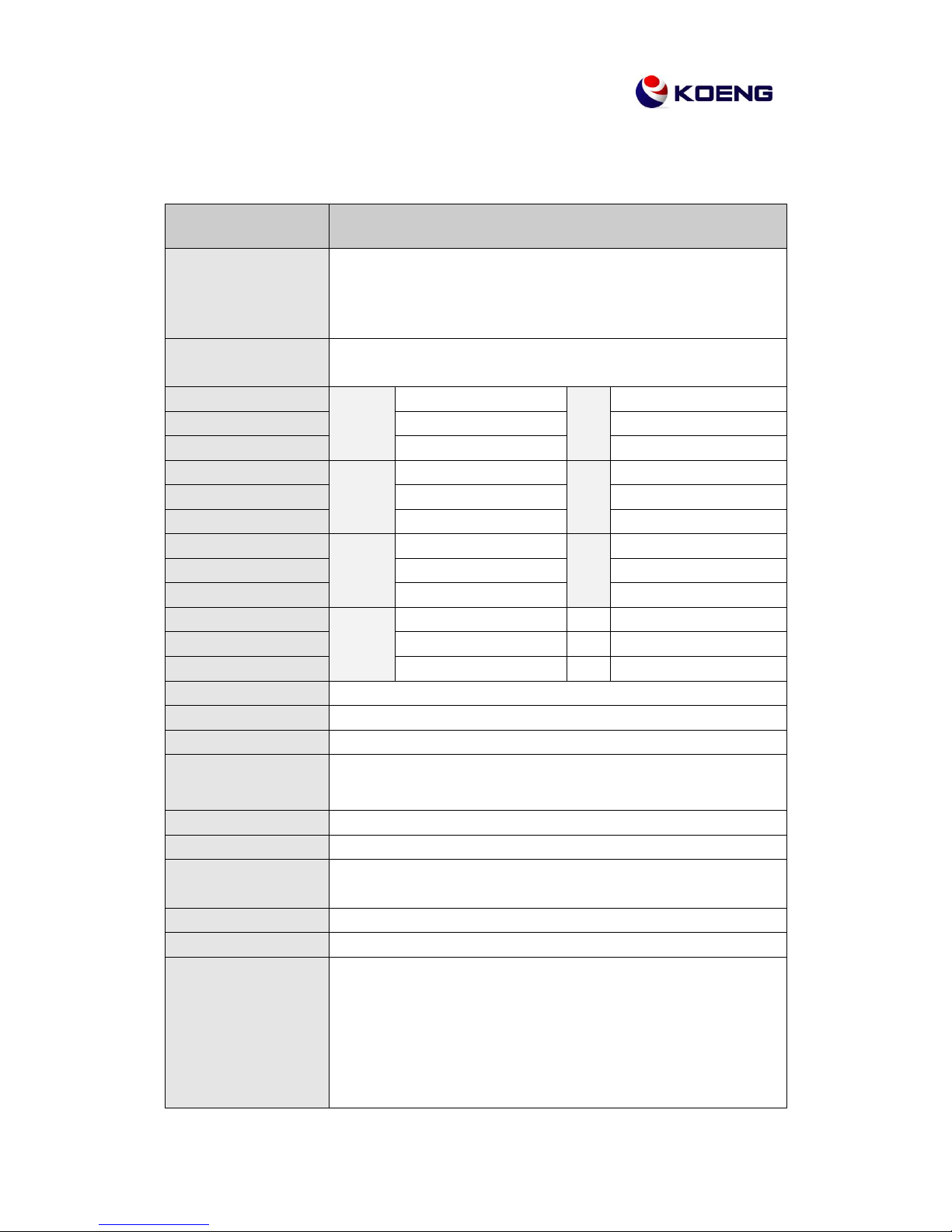
3-1 Specification
KEG – 500
Measuring item
CO(carbon monoxide),HC(Hexane), CO2(carbon dioxide),
O2(Oxygen), Lambda(air surplus rate),
AFR, NOX (optional)
Measuring
method
CO, HC, CO2 : NDIR Method
O2, NOx : Electrochemical Cell
Measuring range
CO
0.00 ~ 9.99%
HC
0 ~ 9999 ppm
Resolution
0.01%
1 ppm
Display
4 digit 7segment LED
4 or 5 digit 7segment LED
Measuring range
CO2
0.0 ~ 20.0%
O2
0.00 ~ 25.00 %
Resolution
0.1%
0.01 %
Display
4 digit 7segment LED
4 digit 7segment LED
Measuring range
Lambda
0 ~ 2.000
AFR
0.0 ~ 99.0
Resolution
0.001
0.1
Display
4 digit 7segment LED
4 digit 7segment LED
Measuring range
NOx
(Option)
0-5000 ppm
Resolution
1 ppm
Display
4 digit 7segment LED
Repeatability
Less than ±2% FS
Response time
Within 10 seconds (more than 90%)
Warming up time
About 2 ~ 8 minutes
Sample collecting
quantity
4 ~ 6 L/min
Power
220V AC or 110V AC ±10% 50 / 60Hz
Power consumption
About 50 W
Operation
temperature
0℃ ~ 40℃
Dimensions
420 (W) × 298 (D) × 180 (H) mm
Weight
About 6.9 kg
Basic accessories
Probe, Probe hose, Spare fuse, Leak test cap,
Spare filter, Operation manual, Power cord,
RS232, Communication cable, Printer, Printer paper
9/63
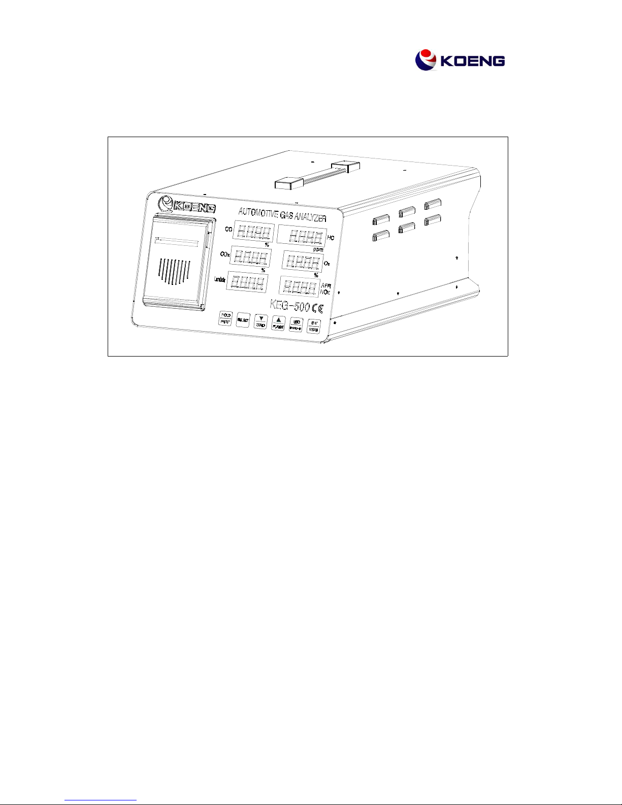
3-2 Appearance
This manual is explaining mainly HOW TO USE 4GAS analyzer. 5GAS analyzer is just
added with NO sensor on 4GAS analyzer. So, for 5GAS analyzer, use this same
manual. You also can use the same manual for motorcycle which emits high density of
HC. Measuring range of the HC is 0 - 20,000 ppm and display window is specially
custom-made in order to indicate 5 digits segments, and for CO, CO2, O2, the display
window is indicating 4 digit segments as in general.
Other features such as the sequence and a series of procedures including GAS
calibration is same as those for 4GAS analyzer. So, you can use the same manuals as
well.
10/63
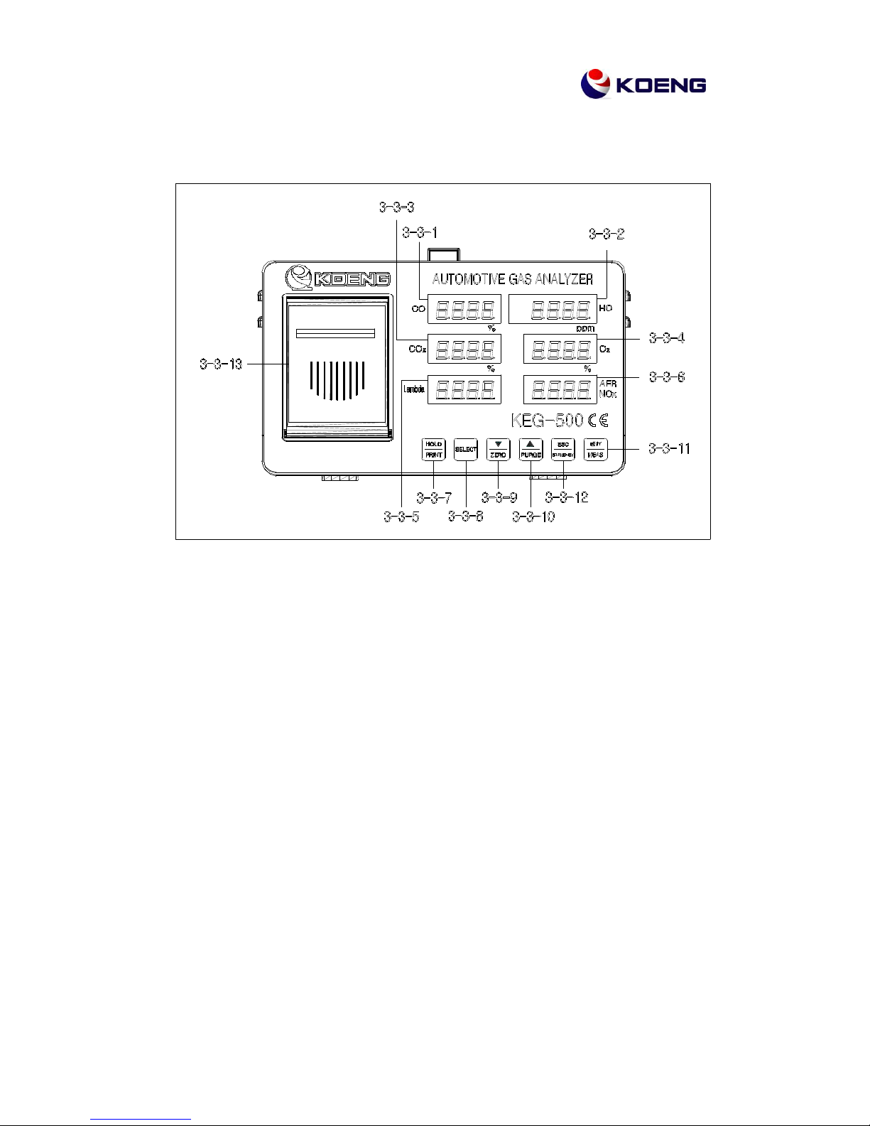
3-3. Front view and description
3-3-1 CO display window
This displays the CO density and program proceeding status.
3-3-2 HC display window
This displays the HC density and program proceeding status.
3-3-3 CO2 display window
This displays the CO2 density and program proceeding status.
3-3-4 O2 display window
This displays the O2 density and program proceeding status.
3-3-5 Lambda display window
This displays the Lambda(air over surplus rate) value and program proceeding status.
3-3-6 AFR/NOx display window
This displays the AFR, NOx, and program proceeding status.
11/63
3-3-7
HOLD
KEY
PRINT
Used in time of holding or printing.
3-3-8
SELECT
KEY
Used in choosing a supplementary function.
3-3-9
▼
KEY
ZERO
Used in time of correcting the datum point or moving a figure or digit.
3-3-10
▲
KEY
PURGE
Used in time of doing a purge or executing a value increase.
3-3-11
ENT
KEY
MEAS
Used in time of measuring or approving a supplementary function.
3-3-12
ESC
KEY
STAND-BY
Used in time of returning to ready mode.
3-3-13
Internal printer case: The print paper comes out this case.
12/63
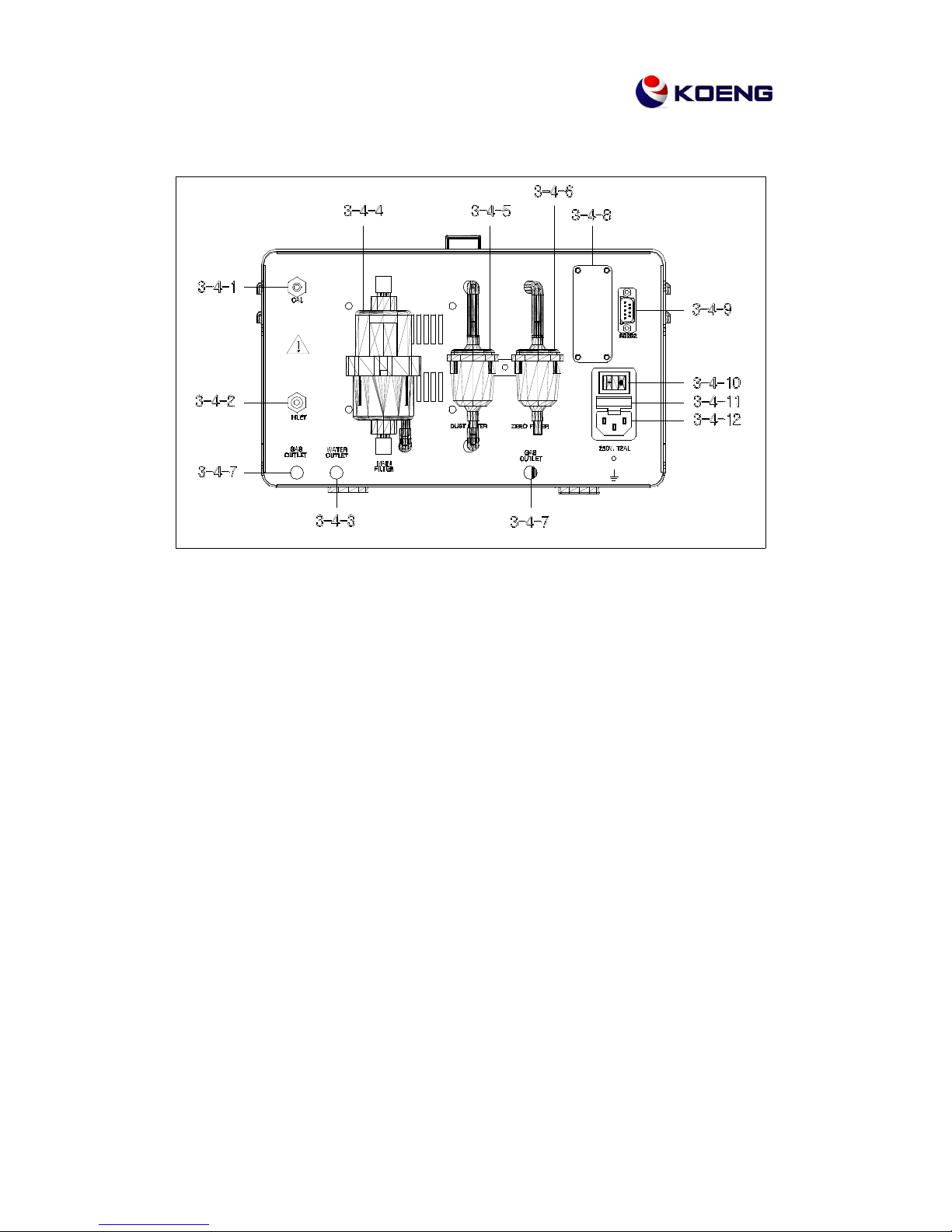
3-4 Rear view and description
3-4-1 CAL(Calibration)
This is a gas inflow gate used in time of standard gas adjustment.
3-4-2 INLET
This is a measuring inlet where one end of the probe mounted into this inlet in time of gas
emission measurement.
3-4-3 WATER OUTLET
This is an emitting outlet where the gas produced in the time of measuring the emitted gas
(4GAS Analyzer) and water to correct the gas is outcome.
3-4-4 MAIN FILTER
This condenses the vapor contained in the automobile emitting gas so that it prevents other
materials from incoming to inside the analyzer at the same time with the water and
measuring gas.
3-4-5 DUST FILTER
This prevents fine dusts and materials from incoming inside the analyzer in the time of
measuring.
3-4-6 ZERO FILTER
This is an activate charcoal filter to purify the analyzer cell in the time of correcting the zero
point.

13/63
3-4-7 GAS OUTLET
This is a emitting outlet where the emitting gas and standard gas is outcome in the time of
adding the NOx.
3-4-8 OPTION
This is a terminal to be directly connected with a normal PC printer.
3-4-9 RS232 PORT
This is a communication terminal through which a PC can operate the
program.
3-4-10 POWER SWITCH
A power on/off terminal of this analyzer.
3-4-11 FUSE BOX
A fuse terminal which will prevent a damage from external voltage overflow.
3-4-12 POWER SOCKET
14/63
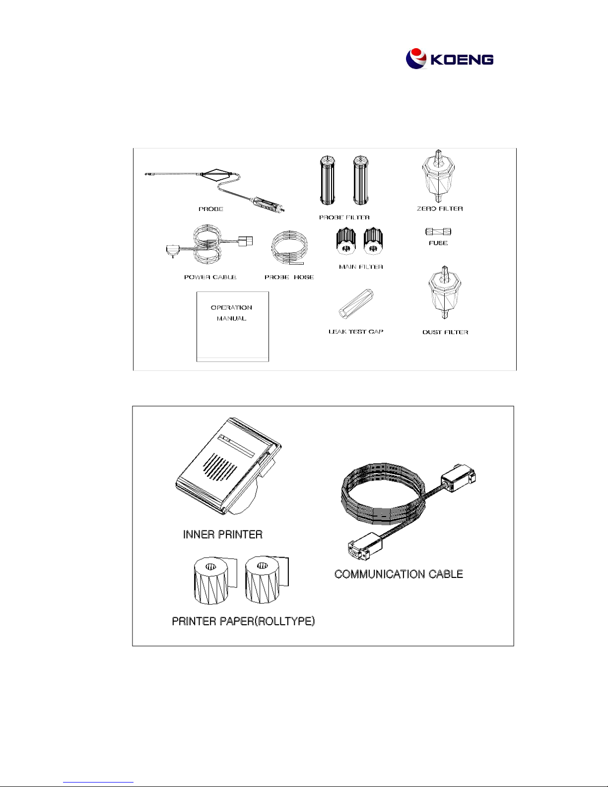
3-5 Basic accessory
3-5-1 Basic accessory
15/63
3-5-2 Basic accessory lists
NO.
PART NAME
PART
NUMBER
Q'TY
1.
PROBE
QG0-M026
1PC
2.
PROBE HOSE
QG0-A015
1PC
3.
LEAK TEST CAP
QG0-A122
1PC
4.
OPERATION MANUAL
QG4-M071
1 COPY
5.
MAIN FILTER
QG0-A017
10PC
6.
DUST FILTER
QG0-A013
5PC
7.
ZERO FILTER
QG0-A014
2PC
8.
PROBE FILTER
QG0-A021
10PC
10.
FUSE (250V 2A)
QG0-E022
2PC
11.
POWER CABLE
QG0-E019
1PC
14.
INNER PRINTER
QG4-M026
1PC
15.
PRINTER PAPER
(ROLL TYPE)
QG4-A062
5PC
16.
COMMUNICATION CABLE
QG4-E080
1PC
** As for the standard gas, we recommend you to buy it from local dealers.
16/63
Chapter 4. Circuits of KEG-500
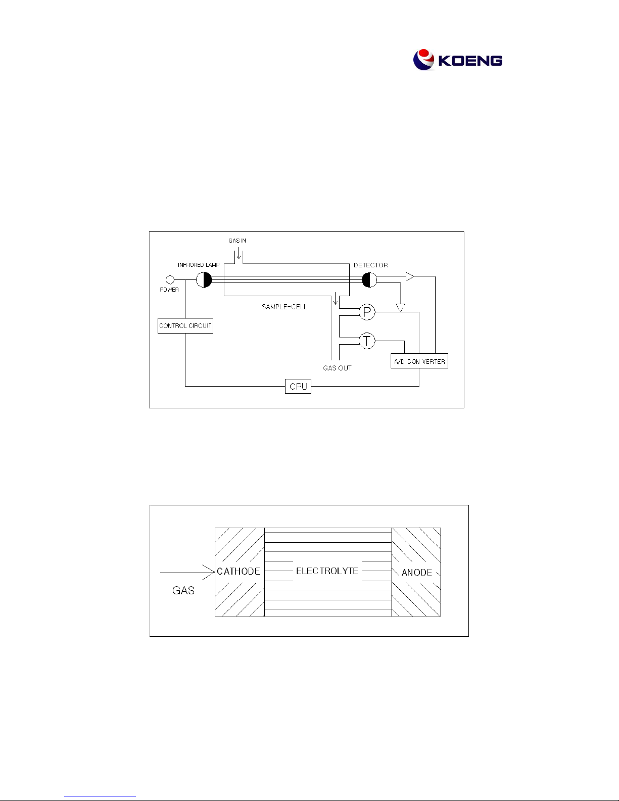
4-1 Measuring principal
This analyzer is configured to perform a measurement by applying Non Dispersive Infra-Red
(NDIR) method for analyzing CO, HC, and CO2, and electrochemical method for analyzing O2
and NOx. In the NDIR analyzing method, a flashing ramp which flashes the infrared rays is
attached at the one end of the sample cell and at the other end a detecting sensor is attached
so that it can detect the component of a gas and then calculate the gas density.
<NDIR method diagram>
The electrochemical method measures the gas density by using the quantity of electron which
produced in the time of oxidation and reducing reaction of the gas.
<Electrochemical method diagram>
17/63
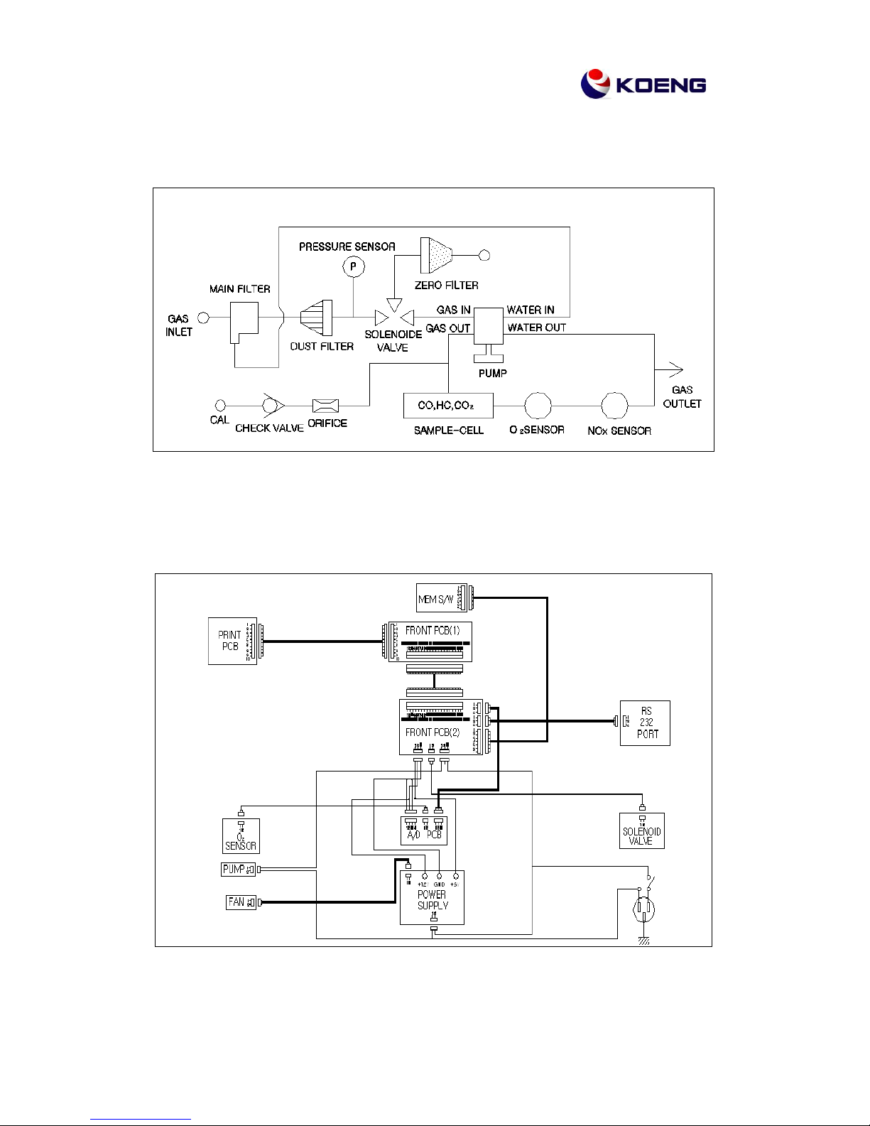
4-2 Guiding diagram
4-3 Electrical circuit diagram

18/63
Chapter 5. Installation Methods and Notes
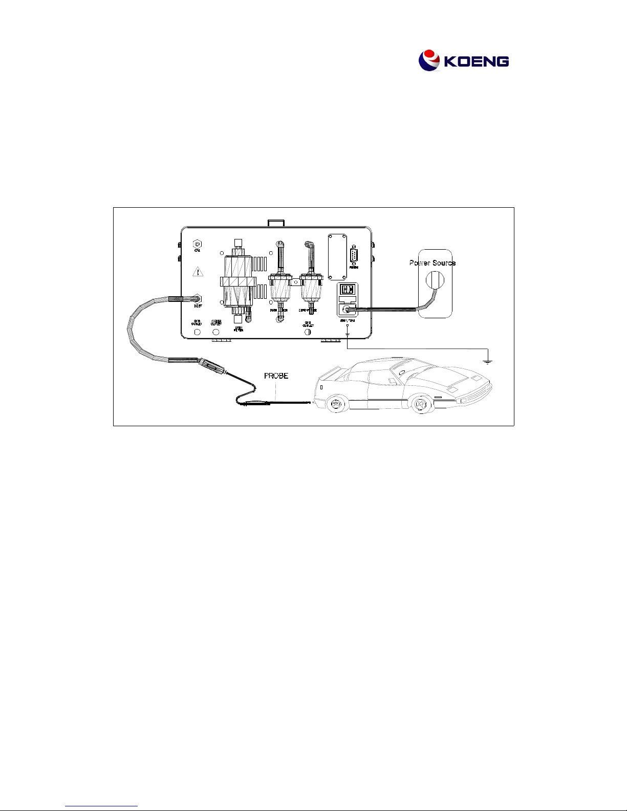
5-1 Installation
5-1-1 Fit end of the probe hose into the measuring probe and the other end of the hose into the
gas inlet in the rear of the analyzer. If the fitting condition is not good and the air comes
into flow from outside, it may yield an incorrect measured value.
Therefore, please carefully verify the fitting condition before use.
5-1-2 Turn off the power switch and then connect the power cable to the power socket located
in the rear of the analyzer
※
Warning
This analyzer supports AC110V only or AC220V only.
(Please confirm the power source to use.)
19/63
5-1-3 Verify the fitting conditions of measuring probe filter and various filters located in the rear
of the analyzer.
5-1-4 Verify again the connection status of the analyzer and then turn on the power switch.
5-1-5 Connect the ground cable to GROUND on the rear of the analyzer.

20/63
5-2 Notes
▶ This analyzer is operated with AC110V only or AC220V only. Please verify the power source
before use. (Note that you can not change power source which is fixed upon supplying this
analyzer.)
▶ The following factors should be considered to properly locate the analyzer body:
━ To be setup in a place of no direct light rays, humidity, vibration and abrupt temperature
change.
━ To be setup in a indoor place where no emitted gas inflows.
━ To be setup in a height higher than 25cm from the ground.
▶ The analyzer should not be moved during the operation. It may cause an
incorrectness in the measured value.
▶ The probe should be located in a place where not affected by the wind.
▶ The probe may be so hot during the operation so that it should be carefully handled not to be
burned in insertion or removal.
▶ It needs to be noted that you should not stay in the gas emitting place during the operation.
▶ The analyzer should be used in a well-ventilated place only because the emitting gas
contains the CO and it can cause a fatal damage to a human body.
▶ This analyzer is Type-approved in accordance with the related government laws so that it is
extremely prohibited to disassemble, change, or rebuild the analyzer and also if you
disassemble the NDIR Module, you may not be guaranteed for the repair.
▶ NDIR module is the core part of the analyzer. Disassembly or assembly work is
possible only by the manufacturer's technician. In any circumstance, you or anyone
else should not attempt to disassemble it. If disassembled or re-assembled, proper
A/S is not going to be possible.
 Loading...