

Koehler K13560, K13270 Operation And Instruction Manual
Operation and Instruction Manual
K13560 / K13270
Automatic Colorimeter
1595 Sycamore Avenue • Bohemia, New York 11716-1796 • USA
Toll Free: 1-800-878-9070 (US only) • Tel: +1 631 589 3800 • Fax: +1 631 589 3815
http://www.koehlerinstrument.com • e-mail: info@koehlerinstrument.com
Petroleum Testing & Analysis Instrumentation • Custom Design & Manufacturing
REV B
Koehler Instrument Company, Inc.


CERTIFICATE OF CONFORMANCE
Portable Automatic Colorimeter
K13560 / K13270
This certificate verifies that part number K13560 / K13270, Portable
Automatic Colorimeter, was manufactured in conformance with the
applicable standards set forth in this certification.
Specifications:
This unit is tested before it leaves the factory, to ensure total functionality
and compliance to the above specifications and ASTM standards. Test and
inspection records are on file for verification.
Jesse Kelly
Application Engineer
Koehler Instrument Company
ASTM D156
ASTM D1209
ASTM D1500
ASTM D1544
ASTM D6045
ISO 4630
ISO 6271
DIN 6162
NF M 07-003
NF T 60-104
JIS K2580


3
Table of Contents
Section 1 Specifications ........................................................................................................................ 7
Section 2 General Information............................................................................................................... 9
2.1 Safety information............................................................................................................................... 9
2.1.1 Precautionary labels .................................................................................................................. 9
2.1.2 Safety around source lamps .................................................................................................... 10
2.1.3 Chemical and biological safety ................................................................................................10
2.2 Overview of product..........................................................................................................................10
Section 3 Installation............................................................................................................................ 13
3.1 Unpacking the instrument................................................................................................................. 13
3.2 Operating environment ..................................................................................................................... 13
3.3 Front and back view.......................................................................................................................... 14
3.4 Power connections ........................................................................................................................... 15
3.5 Interfaces.......................................................................................................................................... 16
3.6 Cuvette compartments and cuvette adapters................................................................................... 16
3.6.1 Cuvette compartments and adapter......................................................................................... 16
3.6.2 Installation of cuvette adapter Z............................................................................................... 17
Section 4 Start Up................................................................................................................................. 19
4.1 Switch on the instrument, startup process........................................................................................ 19
4.2 Language selection........................................................................................................................... 19
4.3 Self-check ......................................................................................................................................... 19
4.4 Sleep mode....................................................................................................................................... 20
4.5 Power off the instrument................................................................................................................... 20
Section 5 Standard programs.............................................................................................................. 21
5.1 Overview........................................................................................................................................... 21
5.1.1 Tips for using the touch screen................................................................................................ 21
5.1.2 Use of the alphanumeric keypad .............................................................................................21
5.1.3 Main menu ...............................................................................................................................22

4
Table of Contents
5.2 Instrument Setup...............................................................................................................................23
5.2.1 Operator ID...............................................................................................................................23
5.2.2 Sample ID.................................................................................................................................24
5.2.2.1 Sample ID with hand-held scanner method 1..................................................................25
5.2.2.2 Sample ID with hand-held scanner method 2..................................................................26
5.2.2.3 Import sample ID list........................................................................................................26
5.2.3 Security settings.......................................................................................................................27
5.2.3.1 Assign operator security level..........................................................................................28
5.2.3.2 Deactivate password .......................................................................................................30
5.2.4 Date and time...........................................................................................................................30
5.2.5 Sound settings..........................................................................................................................32
5.2.6 PC and printer ..........................................................................................................................32
5.2.6.1 Printer setup ....................................................................................................................33
5.2.6.2 Print data .........................................................................................................................34
5.2.6.3 Print data continuously ....................................................................................................34
5.2.6.4 Network setup..................................................................................................................35
5.2.7 Power Management .................................................................................................................38
5.3 Save, recall, send and delete data....................................................................................................38
5.3.1 Color values .............................................................................................................................38
5.3.1.1 Automatic/manual color value storage ............................................................................39
5.3.1.2 Recall color values from the measured data memory .....................................................39
5.3.1.3 Send color values from the measured data memory.......................................................41
5.3.1.4 Delete color values from the measured data memory.....................................................42
5.3.2 Control charts for data from the AQA Log................................................................................42
5.3.3 Data log (only
K13560).............................................................................................................43
5.3.3.1 Automatic/manual saving of single and multi-wavelength measurements ......................44
5.3.3.2 Recall single and multi-wavelength measurements from the measured data memory ...44
5.3.3.3 Send single and multi-wavelengths from the measured data memory............................46
5.3.3.4 Delete single and multi-wavelengths from the measured data memory..........................47
5.3.4 Wavelength scan and time course (K13560 only)....................................................................47
5.3.4.1 Data storage from wavelength scan or time course ........................................................48
5.3.4.2 Recall stored data from wavelength scan or time course................................................48
5.3.4.3 Send data from wavelength scan or time course ............................................................49
5.3.4.4 Delete stored data from wavelength scan or time course ...............................................50
5.3.5 Trends ......................................................................................................................................50
5.4 Take and prepare samples................................................................................................................53

5
Table of Contents
5.5 Color measurement .......................................................................................................................... 54
5.5.1 Take a color measurement ...................................................................................................... 55
5.5.1.1 Touch-sensitive areas in measurement mode................................................................ 55
5.5.1.2 Parameter setup options.................................................................................................56
5.5.1.3 Change the color scale after a measurement................................................................. 57
5.5.1.4 Change the measuring range after a measurement ....................................................... 58
5.5.2 Determination of the iodine color value....................................................................................58
5.5.3 Determination of the Hazen color value (Pt-Co or APHA method) .......................................... 58
5.5.4 Determination of the Gardner color value................................................................................ 59
5.5.5 Determination of the Mineral oil color value (ASTM D 1500 and ISO 2049)............................ 59
5.5.6 Determination of the Saybolt color number (ASTM D 156)...................................................... 59
5.5.7 Color determinations only by
K13560 ...................................................................................... 60
5.5.7.1 Color determination according to the European Pharmacopoeia (EP)........................... 60
5.5.7.2 Color determination according to the US Pharmacopoeia (USP)................................... 63
5.5.7.3 Color determination according to the Chinese Pharmacopoeia (CP) ............................. 64
5.5.7.4 Determination of the Klett color value............................................................................. 64
5.5.7.5 Determination of the AOCS Cc 13 e (Lovibond
®
) scale.................................................. 65
5.5.7.6 Determination of the Yellowness Index (ASTM D 1925)................................................. 65
5.5.7.7 Determination of the Hess-Ives color number................................................................. 65
5.5.7.8 Determination of the ADMI color number........................................................................ 65
5.5.7.9 Determination of the Acid wash color ............................................................................. 66
5.5.7.10 Determination of the ICUMSA color index .................................................................... 66
5.6 Measurement of color differences (K13560 only)............................................................................. 67
5.6.1 Take a color difference measurement ..................................................................................... 67
5.6.1.1 View graph/table/values..................................................................................................69
5.6.2 Take a color difference measurement with stored reference values ....................................... 70
5.6.3 Add a reference to the reference list........................................................................................ 70
5.7 Photometry (K13560 only) ................................................................................................................ 7
1
5.7.1 Single Wavelength (absorbance, concentratio
n and transmittance readings)......................... 71
5.7.1.1 Set up Single Wavelength mode..................................................................................... 71
5.7.1.2 Take single wavelength readings (single reading).......................................................... 73
5.7.2 Multi Wavelength mode – readings with more than one wavelength....................................... 73
5.7.2.1 Set the Reading mode at different wavelengths ............................................................. 73
5.7.2.2 Complete a reading in the Multi Wavelength mode ........................................................ 76
5.7.3 Time course of absorbance/transmittance............................................................................... 76
5.7.3.1 Time course setup parameters ....................................................................................... 76
5.7.3.2 Time course scan reading............................................................................................... 78
5.7.3.3 Analysis of time course data ........................................................................................... 78
5.7.4 Wavelength Scan mode – recording of absorbance and transmission spectrums .................. 79
5.7.4.1 Set up the wavelength scan............................................................................................ 80
5.7.4.2 Perform a wavelength scan ............................................................................................ 82
5.7.4.3 Work with reference scans.............................................................................................. 83

6
Table of Contents
Section 6 Advanced Operations ..........................................................................................................87
6.1 System Checks .................................................................................................................................87
6.1.1 Instrument Information .............................................................................................................87
6.1.2 Update the instrument software ...............................................................................................87
6.1.2.1 Software update with USB memory.................................................................................87
6.1.2.2 Software update with network connection.......................................................................88
6.1.3 Optical Checks .........................................................................................................................88
6.1.4 AQA Analytical Quality Assurance ...........................................................................................90
6.1.4.1 Standard Configuration....................................................................................................90
6.1.4.2 Perform AQA Standard Measurement.............................................................................91
6.1.5 Instrument backup....................................................................................................................92
6.1.6 Service menu ...........................................................................................................................93
6.1.7 Service time..............................................................................................................................93
6.1.8 Lamps operating time...............................................................................................................93
6.2 Toolbar ..............................................................................................................................................94
6.2.1 Log on ......................................................................................................................................94
6.2.2 Sample ID.................................................................................................................................94
6.2.3 Timer ........................................................................................................................................95
6.2.4 AQA..........................................................................................................................................95
6.2.5 Trends ......................................................................................................................................95
6.2.6 K13560/K13270 Website..........................................................................................................95
Section 7 Maintenance.....
..........................................
...........................................................................97
7.1 Cleaning requirements ......................................................................................................................97
7.1.1 Spectrophotometer...................................................................................................................97
7.1.2 Screen ......................................................................................................................................97
7.1.3 Cuvettes/cells...........................................................................................................................98
7.2 Lamp replacement.............................................................................................................................98
7.3 Cell compartment (2) replacement..................................................................................................100
Section 8 Troubleshooting .................................................................................................................103
Section 9 Replacement Parts.............................................................................................................107
9.1 Accessories.....................................................................................................................................107
9.2 Replacement Parts..........................................................................................................................107

7
Section 1 Specifications
These are subject to change without notice!
Performance specifications K13560 K13270
Display mode
Color measurement, color difference
measurement, absorbance and
concentration
Color measurement
Color measurement 26 color ratios 5 color ratios
Colorimetric evaluation
All visual color ratios are calculated for standard light chart C and 2° standard
observers in accordance with DIN 5033. Colorimetric color values can be switched
to light type A, C, D65 and 2° or 10° standard observers.
Source lamp Halogen lamp
Wavelength range 320–1100 nm
Wavelength Accuracy ± 1.5 nm (wavelength range 340–900 nm)
Wavelength reproducibility ≤ 0.1 nm
Wavelength resolution 1 nm
Wavelength calibration Automatic
Wavelength range for color
measurement
380–720 nm steps of 10 nm
Scanning speed ≥ 8 nm/sec (in steps of 1 nm)
Spectral bandwidth 5 nm
Photometric measuring range ± 3 Abs (wavelength range 340–900 nm)
Photometric accuracy
5 m Abs at 0.0–0.5 Abs,
1 % at 0.50–2.0 Ext
Photometric linearity
< 0.5 % to 2 Abs
≤ 1 % at > 2 Abs with neutral glass at 546 nm
Stray light < 0.1 % T at 340 nm with NaNO
2
Data log
3000 color measurements,
100 color reference values,
1000 photometric measurements,
20 wavelength scans, 20 time scans
400 color measurements
Physical and environmental specifications
Width 350 mm (13.78 in)
Height 151 mm (5.94 in)
Depth 255 mm (10.04 in)
Earth 4200 g (9.26 lb)
Ambient operating requirements
10–40 °C (50–104 °F), maximum 80 % relative humidity (without condensate
formation)
Ambient storage requirements
–40–60 °C (–40–140 °F), maximum 80 % relative humidity (without condensate
formation)
Additional technical data
Power connector via external power
supply
Input: 100–240 V/47–63 Hz
Output: 15 V/40 VA

8
Specifications
Interfaces
Use only shielded cable with maximum length of 3 m:
2× USB type A
1× USB type B
Use only shielded cable (for example STP, FTP, S/FTP) with maximum length of
20 m:
1× Ethernet
Housing rating IP40 (excluding interfaces and power supply)
Protection class Class I
Performance specifications K13560 K13270
9
Section 2 General Information
2.1 Safety information
Read through the entire user manual carefully before you unpack
the device, set up and put into operation. Pay attention to all
danger and caution statements. Failure to do so could result in
serious injury to the operator or damage to the equipment.
To make sure that the protection provided by this instrument is
not impaired, do not use or install this instrument in any manner
other than that specified in these operating instructions.
Note: Information that supplements points in the main text.
2.1.1 Precautionary labels
Read all labels and tags attached to the instrument. Personal
injury or damage to the instrument could occur if not observed.
For symbols attached to the device, corresponding warning notes
are found in the user manual.
DANGER
Indicates a potentially or imminently hazardous situation that, if not
avoided, results in death or serious injury.
WARNING
Indicates a potentially or imminently hazardous situation that, if not
avoided, may result in death or serious injury.
CAUTION
Indicates a potentially hazardous situation that may result in minor or
moderate injury.
NOTICE
Indicates a situation that, if it is not avoided, can lead to damage to
the device. Information that requires special emphasis.
This symbol may be attached to the device and references the operation- and/or safety notes in the user manual.
This symbol on the device is an indication of hot surfaces.
Electrical equipment marked with this symbol may not be disposed of in European domestic or public disposal
systems after 12 August 2005. In conformity with European local and national regulations (EU Directive
2002/96/EC), European electrical equipment users must now return old or end-of life equipment to the
manufacturer for disposal at no charge to the user.
Note: For return for recycling, please contact the equipment manufacturer or supplier for instructions on how to
return end-of-life equipment, manufacturer-supplied electrical accessories, and all auxiliary items for proper disposal.

10
General Information
2.1.2 Safety around source lamps
The source lamp is operated at high temperatures.
To prevent electric shock, disconnect the instrument from the
power source before replacing the lamp.
2.1.3 Chemical and biological safety
Normal operation of this device may require the use of chemicals
or samples that are biologically unsafe.
• Observe all cautionary information printed on the original
solution containers and safety data sheets prior to their use.
• Dispose of all consumed solutions in accordance with the
local and national regulations and laws.
• Select the type of protective equipment suitable to the
concentration and quantity of the dangerous material being
used.
2.2 Overview of product
The K13560 and K13270 instruments are VIS
spectral-photometers with wavelength ranges from 320 to
1100 nm. The instruments can perform a precise colorimetric
analysis in accordance with ISO/ASTM standards with a single
measurement and display the result in the form of classic color
systems such as iodine, Hazen or Gardner color values. The
instruments support multiple languages.
The K13560 is supplied with 26 color value calculations, while
the K13270 is supplied with five colo
r value calculations (Iodine
color, Hazen color, Gardner color, Saybolt
color and ASTM D
1500 color numbers).
WARNING
The manufacturer is not responsible for any damages due to
misapplication or misuse of this product including, without limitation,
direct, incidental and consequential damages, and totally excludes
such damages as permitted under applicable laws.
The user is solely responsible to identify critical application risks and
install appropriate mechanisms to protect processes during a possible
equipment malfunction.
CAUTION
Burn hazard. Allow the lamp(s) to cool for at least 30 minutes before
maintaining/replacing them.
DANGER
Potential danger with contact with chemical/biological substances.
Working with chemical samples, standards and reagents can be
dangerous.
Make yourself familiar with the necessary safety procedures and the
correct handling of the chemicals before use and read and follow all
relevant safety data sheets.

11
General Information
The K13560 contains the following programs and operating
modes in addition to the color measurement: single wavelength
mode, multi-wavelength mode, wavelength scan and time scan
mode. The digital measurements are displayed in the
dimensional units of concentration, absorbance or %
transmittance, making the K13560 universally suitable for lab
analysis.

12
General Information
13
Section 3 Installation
3.1 Unpacking the instrument
The following components are supplied as standard with the
K13560/K13270:
• K13560/K13270 spectrophotometer
• Dust cover
• USB dust cover
, fitted as s
tandard
• Table power supply with power cord
• Cuvette adapter Z, installed as standard
• Basic user manual
• CD-ROM with detailed operating instructions
Note: If any of these items are missing or damaged, please contact the
manufacturer or a sales representative immediately.
3.2 Operating environment
Observe the following points to allow the instrument to function
normally and give a long operating life.
• Position the instrument securely on a flat surface taking care
to remove any objects from under the device.
• The ambient temperature must be 10–40 °C (50–104 °F).
• The relative humidity should be less than 80 %; moisture
should not condense on the instrument.
• Leave at least a 15 cm clearance at the top and on all sides
for air circulation to avoid overheating of electrical parts.
• Do not use or store the device in extremely dusty, humid or
wet places.
• Keep the surface of the instrument, the cell compartment and
all accessories clean and dry at all times. Immediately
remove splashes or spilt materials on or in the instrument
(refer to Section 7).
WARNING
Electrical and fire hazards.
Only use the supplied benchtop power supply.
Only qualified experts may perform the tasks described in this section
of the manual, while adhering to all locally valid safety regulations.
NOTICE
Protect the instrument from extreme temperatures from heaters,
direct sunlight and other heat sources.
14
Installation
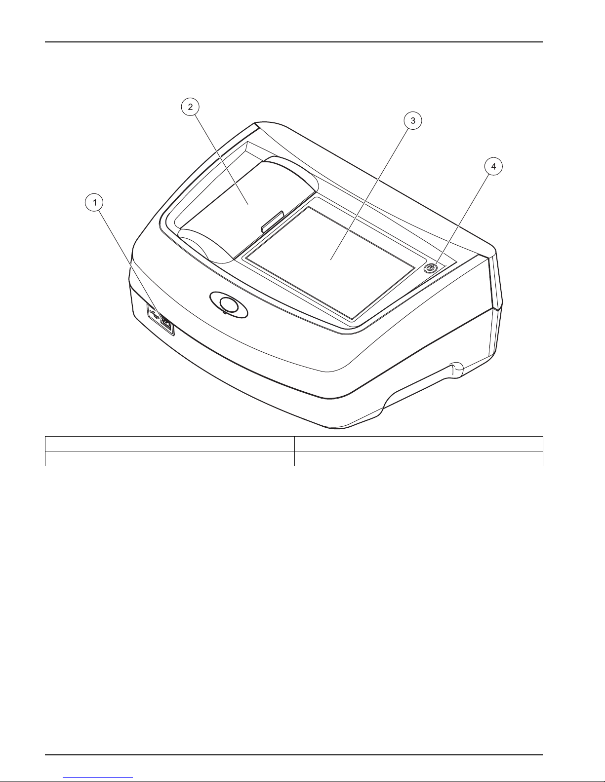
3.3 Front and back view
Figure 1 Front view
1 USB port type A 3 Touch screen
2 Cuvette compartment cover 4 On/off switch
15
Installation
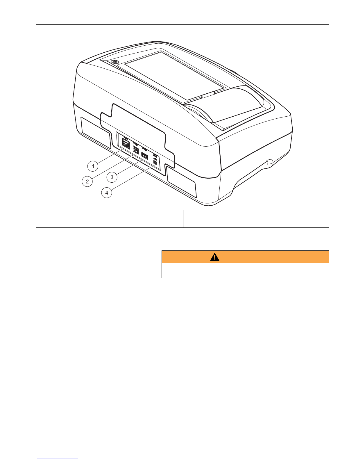
Figure 2 Back view
3.4 Power connections
1. Connect the power cable to the benchtop power supply.
2. Plug the benchtop power supply cable into the back of the
instrument (Figure 2, page 15).
3. Insert the power cable plug into a mains socket
(100–240 V~/47–63 Hz).
4. Turn on the power switch next to the screen to activate the
power supply (Figure 1, page 14).
Note: If you do not intend to use the instrument for a long period,
disconnect it from the power supply.
Note: Make sure the socket you are using is easily accessible.
1 Ethernet port 3 USB port type A
2 USB port type B 4 Connection for benchtop power supply
WARNING
Electrical and fire hazards.
Only use the supplied benchtop power supply.

16
Installation
3.5 Interfaces
The instrument has three USB ports and one Ethernet port as
standard. They are located on the front and rear of the instrument
(Figure 1 Figure 2, page 15).
The USB type A ports are used for communications with a printer,
USB memory stick or keyboard. A USB memory stick can be
used to update the instrument software.
The USB type B port is used for communications with a PC. The
optional Hach Lange Online Data software must be installed on
the PC for this use.
A USB hub may be used to connect several accessories at a
time.
Note: USB cables must not be longer than 3m.
These USB ports permit data to be exported to a printer or PC
and also allow the instrument software to be upgraded (refer to
section 6.1.2, page 87). The Ethernet port supports real-time data
transfer in local networks, LIMS systems or SC controllers. Only
use a shielded cable (e.g. STP, FTP, S/FTP) with a maximum
length of 20 m for the Ethernet port.
3.6 Cuvette compartments and cuvette adapters
3.6.1 Cuvette compartments and adapter
Open the cuvette compartments by sliding the cuvette
compartment cover to the left.
The cover lowers to the side next to the cuvette compartments.
Note: If there are long intervals between uses, close the cuvette
compartment cover to protect the optics of the instrument from dust and
impurities.
The instrument has two cuvette compartments (Figure 3). Only
one cell type at a time can be used for a reading.
Cell compartment (1) for:
• 11 mm round cuvettes
Note: Insert cuvette adapter Z into the cuvette compartment (2).
Table 1 Interfaces
Interfaces Description
USB (Type A) This USB port can be used to connect a printer, a USB memory stick or a keyboard.
USB (Type B)
This USB port is intended only for the connection between the instrument and a PC (when the
relevant software is installed).
Ethernet
The Ethernet port is intended for data transfer to a PC without installed software or in a local
network . Only use a shielded cable (e.g. STP, FTP, S/FTP) with a maximum length of 20 m for
the Ethernet port.

17
Installation
Cell compartment (2) for:
The following cell types can be used in cell compartment (2).
• Without cuvette adapter Z in the cuvette compartment (2),
you can insert 50 mm cuvettes.
• With cuvette adapter Z: 10 mm square cuvettes.
Note: These cuvettes must be inserted with cuvette adapter Z.
Note: In the event of severe contamination, you can replace the cuvette
compartment (2) (see chapter 7.3, page 100).
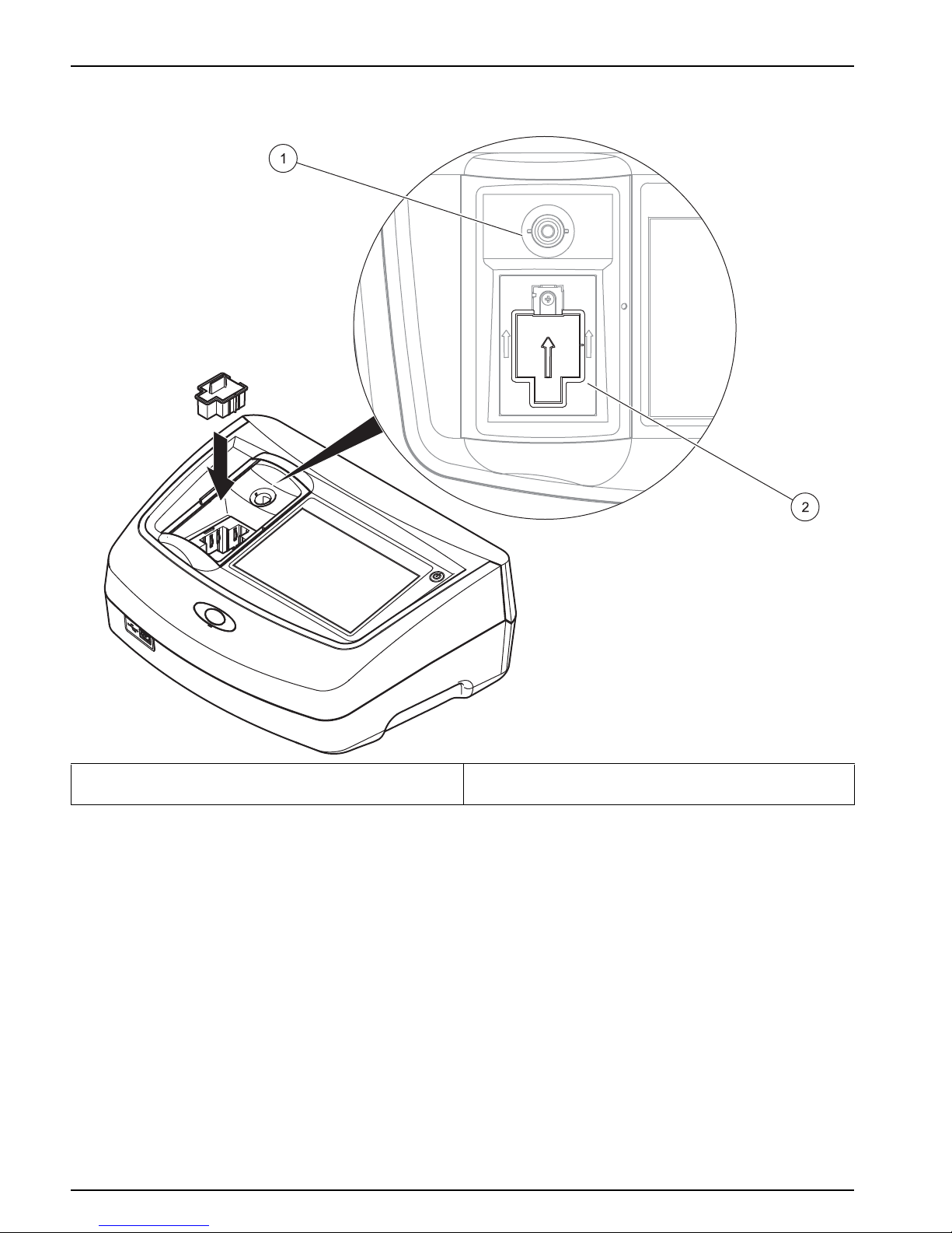
3.6.2 Installation of cuvette adapter Z
1. Open the cuvette compartment.
2. Insert cuvette adapter Z into the cuvette compartment (2) so
that the arrow on the cuvette adapter is pointing toward the
cuvette compartment (1) (Figure 3).
Note: The arrow on the cuvette adapter indicates the direction of the
light beam path.
18
Installation
Figure 3 Cuvette compartments and cuvette adapter Z
1 Cuvette compartment (1) for round cuvettes 2 Cuvette compartment (2) for square cuvettes, cuvette
adapter Z installed
19
Section 4 Start Up
4.1 Switch on the instrument, startup process
1. Connect the power cable to the mains outlet.
2. Switch on the instrument by pressing the power switch next
to the screen.
3. The instrument starts automatically with a startup process
lasting approximately 45 seconds. The screen displays the
manufacturer's logo. At the end of the startup process, a
startup melody is heard.
Note: Wait approximately 20 seconds before switching on again so as
not to damage the electronics and mechanics of the instrument.
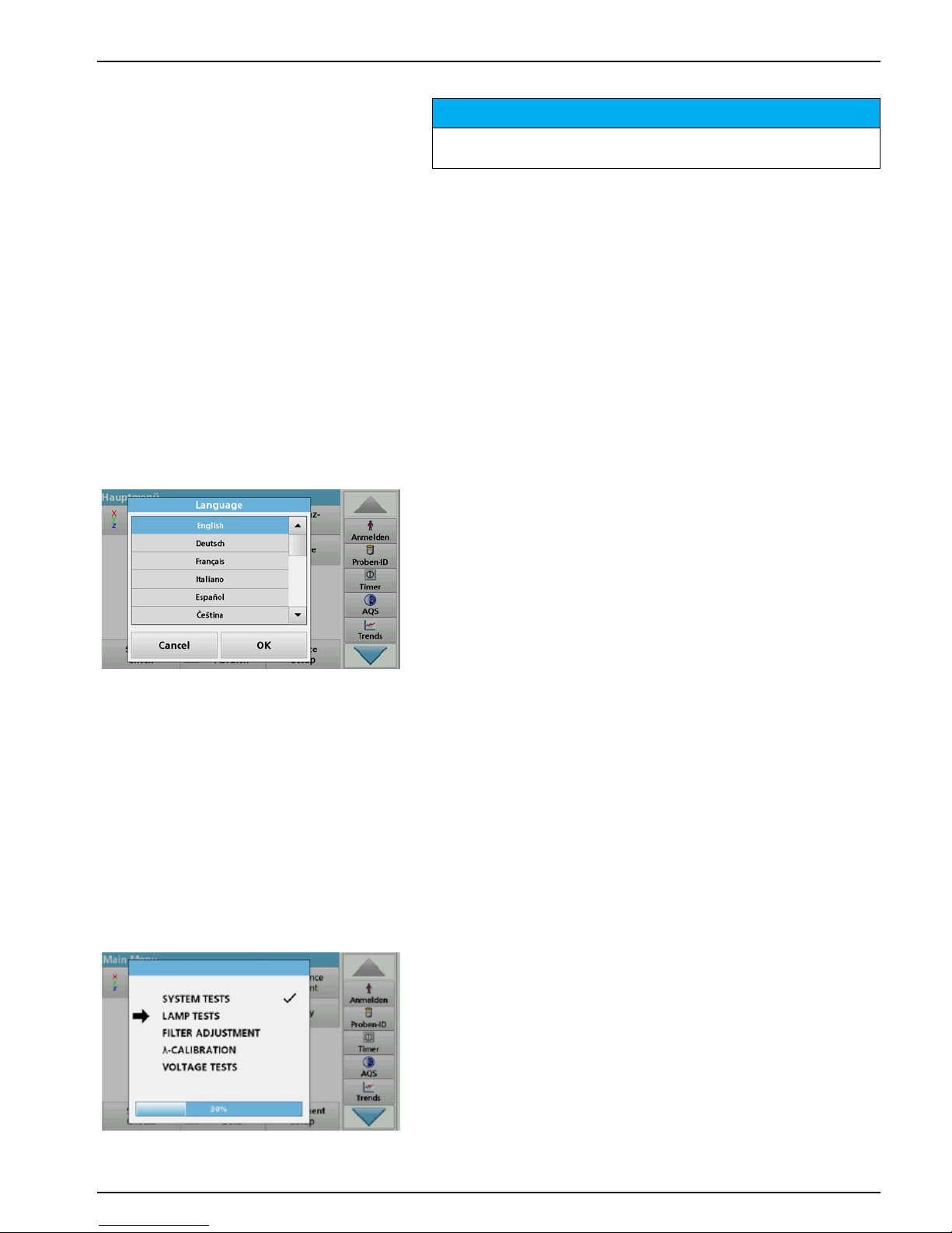
4.2 Language selection
The software supports multiple languages. The first time the
instrument is switched on, the language selection screen will be
shown automatically after the startup process.
1. Select the required language.
2. Press OK to confirm the language selection. The self-check
will then start automatically.
Change the language setting
The instrument functions in the selected language until the option
is changed.
1. Turn the instrument on.
2. During the startup process, touch any point on the screen
and maintain contact until the option for selecting a language
is shown (approximately 45 seconds).
3. Select the required language.
4. Press OK to confirm the language selection. The self-check
will then start automatically.
4.3 Self-check
Each time the instrument is powered up, a test program begins.
During the course of this program (approx. 25 seconds), system
tests, lamp tests, filter calibration, wavelength calibration and
voltage tests can be carried out. Each test that functions correctly
is marked accordingly.
Note: For error messages during the test program, refer to Section 8,
page 103.
NOTICE
All screen displays in this operating manual correspond to the
K13560. The screen displays of the K13270 may differ.
20
Start Up
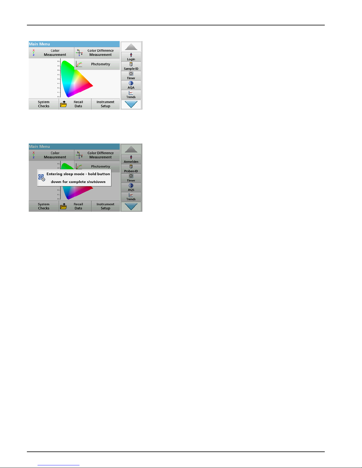
The Main Menu is displayed when diagnostics are completed.
Note: section 5.1.3, page 22 contains a detailed description of the main
menu.
4.4 Sleep mode
The instrument can be put into sleep mode.
1. Briefly press the power switch next to the screen.
The "Sleep mode" message is shown. The screen will then
switch off automatically.
2. To switch on, press the power switch next to the screen.
The self-check will start automatically.
After that, the instrument is ready to use.
4.5 Power off the instrument
1. Press the power switch next to the screen for
approx. 5 seconds.
21
Section 5 Standard programs
5.1 Overview
5.1.1 Tips for using the touch screen
The whole screen responds to touch. To choose an option, tap
with a fingernail, fingertip, an eraser or a specialised stylus. Do
not touch the screen with sharp objects, such as the tip of a
ballpoint pen.
• Do not place anything on top of the screen, to prevent
damage or scratching on the screen.
• Press buttons, words or icons to select them.
• Use scroll bars to move up and down long lists very quickly.
Press and hold the scroll bar, then move up or down to move
through the list.
• Highlight an item from a list by pressing it once. When the
item has been successfully selected, it will be displayed as
reversed text (light text on a dark background).
5.1.2 Use of the alphanumeric keypad
This display is used to enter letters, numbers and symbols as
needed when programming the instrument. Unavailable options
are disabled (grayed out). The icons on the right and left of the
screen are described in Table 2.
The central keypad changes to reflect the chosen entry mode.
Press a key repeatedly until the desired character appears on the
screen. A space can be entered by using the underscore on the
YZ_ key.
Press Cancel to cancel an entry, or press OK to confirm an entry.
Note: It is also possible to use a USB keyboard (with US keyboard
layout) or a hand-held USB barcode scanner (refer to Section 9,
page 107).
Table 2 Alphanumeric keypad
Icon / key Description Function
ABC/abc Alphabetic Toggles the character input mode between upper and lower case.
# % Symbols Punctuation, symbols and numerical sub- and superscripts may be entered..
123 Numeric For entering regular numbers..
CE Clear Entry Clear the entry.
Left Arrow Back Deletes the current character and goes back one position.
Right Arrow Next Navigates to the next space in an entry.

22
Standard programs
5.1.3 Main menu
A variety of modes may be selected from the Main Menu. The
following table briefly describes each menu option.
There is a toolbar on the right-hand side of the screen. Press to
activate the various functions.
Table 3 Main Menu options
Option Function
Color measurement
The
COLOR MEASUREMENT MODE is used to determine color values such as Hazen,
Gardner and Saybolt. The K13560 also offers three-dimensional, absolute
colorimetric values, as well as the color scales of CIE L*a*b*, Hunter Lab or the
European Pharmacopoeia.
Color difference measurement
(only K13560)
The mode for
COLOR DIFFERENCE MEASUREMENT is used to determine a
quantitative color difference between a reference (R) and a sample (P) in the
three-dimensional color space (CIE L*a*b* or Hunter Lab). In this mode, an additional
reference memory for up to 100 references is available.
Photometry
(only
K13560)
Single Wavelength
Single wavelength readings are:
Absorbance readings: The light absorbed by the sample is measured in absorbance
units.
Transmittance reading (%): Measures the percent of the original light that passes
through the sample and reaches the detector.
Concentration readings: A concentration factor can be entered to enable the
measured absorbance values to be converted into concentration values.
Multi Wavelength
In the Multi Wavelength mode, absorbance (Abs) or percentage transmittance (%T) is
measured at up to four wavelengths and absorbance differences and absorbance
relationships are calculated. Simple conversions into concentrations can also be
carried out.
Time course
The time scan records the absorbance or % transmittance at a wavelength over a
defined time.
Wavelength Scan
A wavelength scan shows how the light from a sample is absorbed over a defined
wavelength spectrum. This function can be used to determine the wavelength at
which the maximum absorbance value can be measured. The absorbance behavior is
displayed graphically during the scan.
System Checks
The "System Check" menu contains a number of options, such as instrument
information, optical checks, instrument backup, service times, instrument update,
settings for analytical quality assurance and lamp history.
Recall measurement data
Saved data can be retrieved, filtered, sent to a printer, memory stick or PC and
deleted.
Instrument Setup
This menu is used to configure user-specific and/or process-specific settings:
operator ID, date and time, security settings, saved data, sound, PC and printer and
energy management.
23
Standard programs
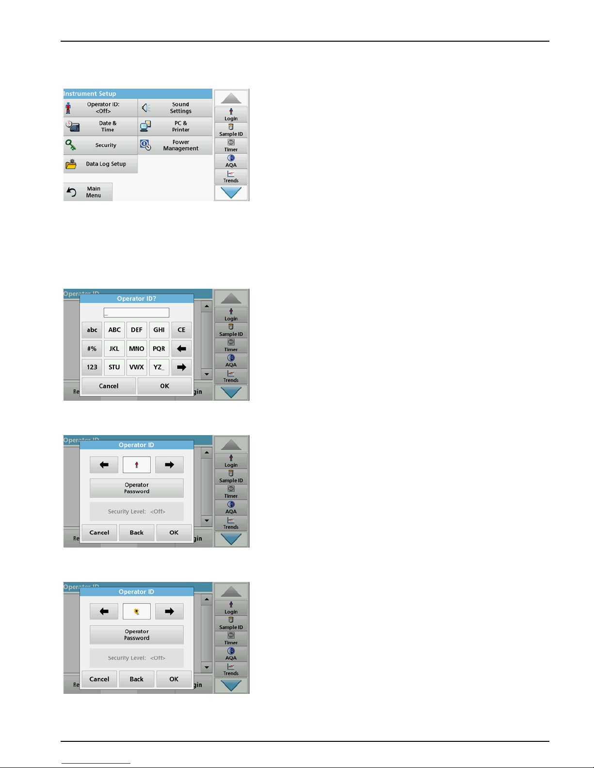
5.2 Instrument Setup
1. In the main menu, select the menu option Instrument setup.
A selection of functions appears in order to configure the
functions of the instrument.
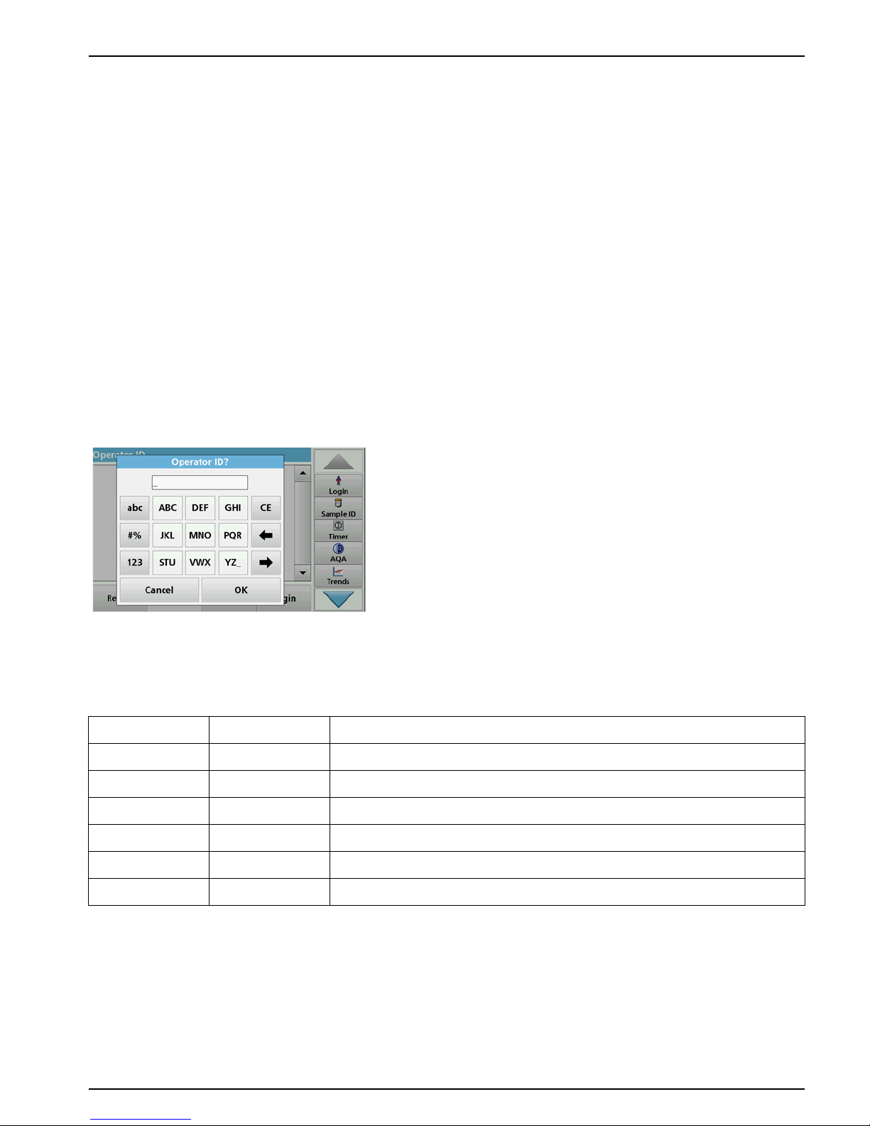
5.2.1 Operator ID
Use this option to enter up to 30 sets of operator initials (up to ten
characters each) into the instrument. This feature helps record
which operator measured each sample.
1. Press Operator ID in "Instrument setup".
2. Press Options > New to enter a new operator ID.
Note: If no operator ID has yet been entered, the alphanumeric
keyboard is immediately displayed.
3. Use the alphanumeric keypad to enter a new operator ID.
4. Press OK to confirm the entry.
5. Choose an icon for the operator ID using the Left Arrow and
Right Arrow.
6. Press Operator password to protect the operator ID with a
password.
7. Use the alphanumeric keypad to enter an operator password.
8. Press OK to confirm the entry.
9. Press Cancel to delete the complete entry for the operator
ID.
Press Back to reach to the input screen for operator ID.
Press OK to confirm the entry. The following screen is
displayed.
24
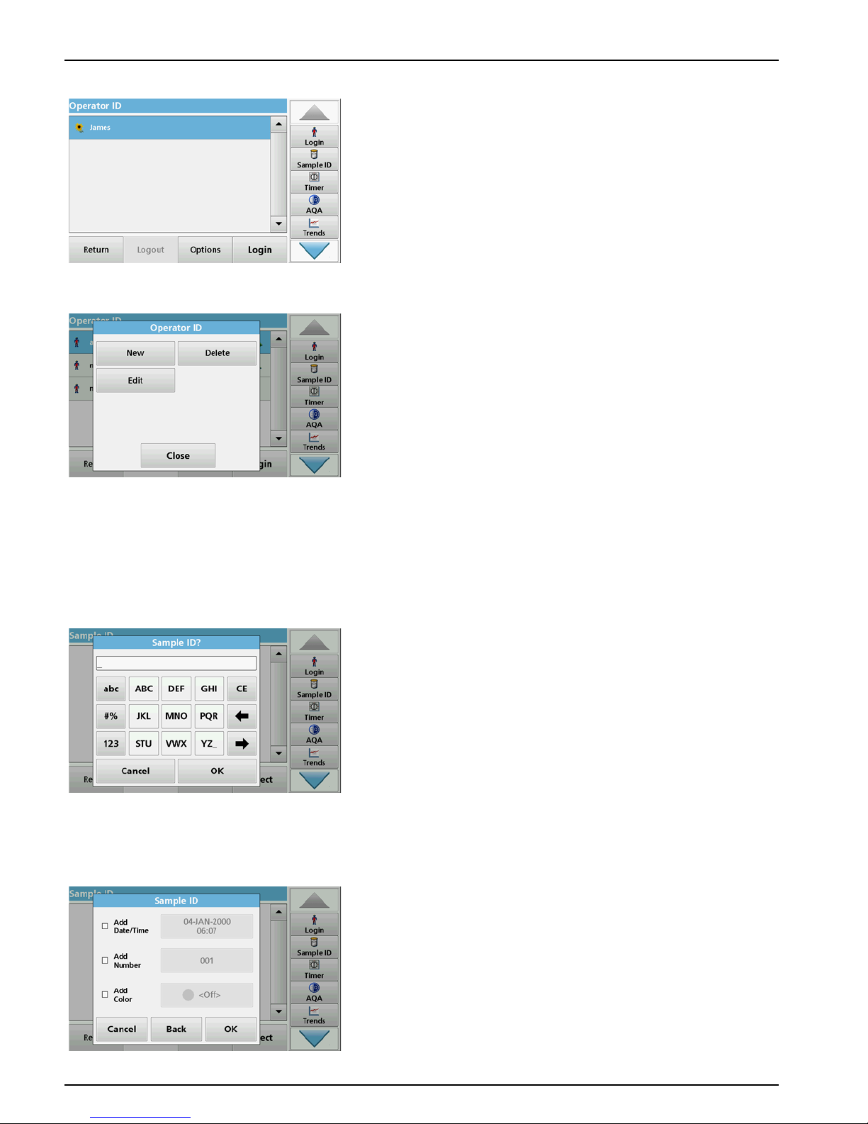
Standard programs
10. With Back the device returns to the menu "Instrument
Setup".
Press Logout to log out of an active operator ID.
Press Login to activate a selected operator ID.
Press Options to enter, change or delete additional operator
IDs. The following screen is displayed.
11. Press New to enter another operator ID.
Press Delete to delete an operator ID.
Press Edit to edit an operator ID.
5.2.2 Sample ID
Use this option to enter up to 100 different sample designations
(up to 20 characters each) into the instrument. Sample IDs can
be used to specify the sample location or other sample specific
information, for example.
1. Press Sample ID in the toolbar on the right.
2. Press New to enter a new sample ID.
Note: If no sample ID has been entered yet, the alphanumeric
keyboard is immediately displayed.
3. Use the alphanumeric keypad to enter a new Sample ID.
Note: If a USB Barcode handset scanner (refer to section 5.2.2.1,
page 25) is connected, Sample IDs can also be scanned.
4. Press OK to confirm the entry.
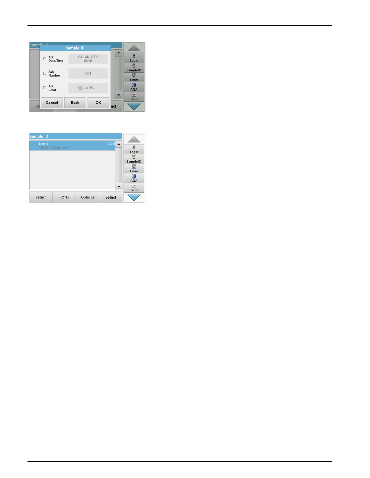
5. Assign the current time and date, a sequential number or a
colour to the sample ID.
25
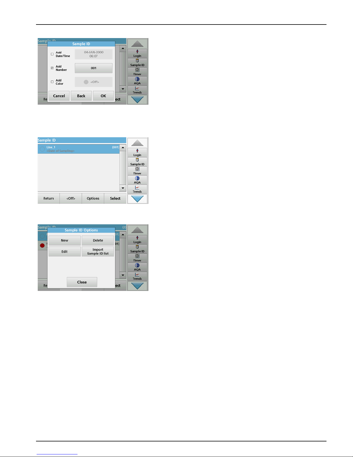
Standard programs
6. To number the sample IDs sequentially (e. g. Inflow (01) etc.),
press Add Number.
• Use the arrow keys to specify the first number of the
sequence.
• Use the key between the arrow keys to enter the first
number of the sequence using the alphanumeric keypad.
7. Press OK to return to the "Instrument Setup" menu.
The Sample ID is activated. Each Sample ID is automatically
numbered in ascending order after a reading. The number is
shown in parentheses behind the Sample ID.
8. Press Back to return the instrument to the "Instrument Setup"
menu.
Press Off to switch off the active sample ID.
Press Select to activate the selected sample ID.
Use Options to enter, change or delete additional sample
IDs. The following screen is displayed:
9. Press New to enter another sample ID.
Press Delete to delete a sample ID.
Press Edit to edit a sample ID.
Select Import Sample ID List to import *.txt and *.csv files
via a USB stick or network; see section 5.2.2.3, page 26.
5.2.2.1 Sample ID with hand-held scanner method 1
1. Connect the hand-held scanner to the USB port.
Successful connection is indicated by a sound.
2. Press Sample ID > Options and NEW.
3. Read barcode with hand-held scanner.
26
Standard programs
4. The sample ID can have the current date and time, a
sequential number and a colour allocated to it.
Select the required options or a colour.
5. Press OK to confirm the entry.
6. Press New again and repeat the process for each barcode.
5.2.2.2 Sample ID with hand-held scanner method 2
1. Read the sample ID in measurement mode with the
hand-held scanner and calibrate the cuvette.
The sample ID is saved togther with the measured value but
is not transferred to the list of sample IDs.
Note: To delete a sample ID, activate the ID by selecting it and pressing
Delete.
Note: A sample ID can be entered or changed in Reading Mode. To do
this, press Options > More > Instrument Setup. If a sample ID is
already assigned, select the "Sample ID" symbol.
5.2.2.3 Import sample ID list
1. Create an external sample ID list with a spreadsheet
program.
Four columns are permitted; column 1 contains the
sequential number, column 2 the sample designation,
columns 3 and 4 are optional.
Headings and comment lines must begin with #.
2. Create a folder named "Sample ID" on a USB stick or in your
established network.
3. Save the sample ID list with Save As in the format CSV or
UNICODE-TXT in the folder "Sample ID".
4. Connect the instrument to the USB stick or network.
All *.TXT and *.CSV files in the Sample ID folder will be
displayed for selection.
27
Standard programs
5. Select the desired file with OK.
6. Transfer the displayed sample ID list with
DONE.
5.2.3 Security settings
The "Security" menu contains a variety of security settings to
control access to various functions.
All functions can be allocated to three different security levels:
• not secured: every operator can make changes in this area.
• one key: every operator assigned this security level can
make changes to non-secured functions and functions with
one key.
• two keys: every operator assigned this security level can
make changes in all functions
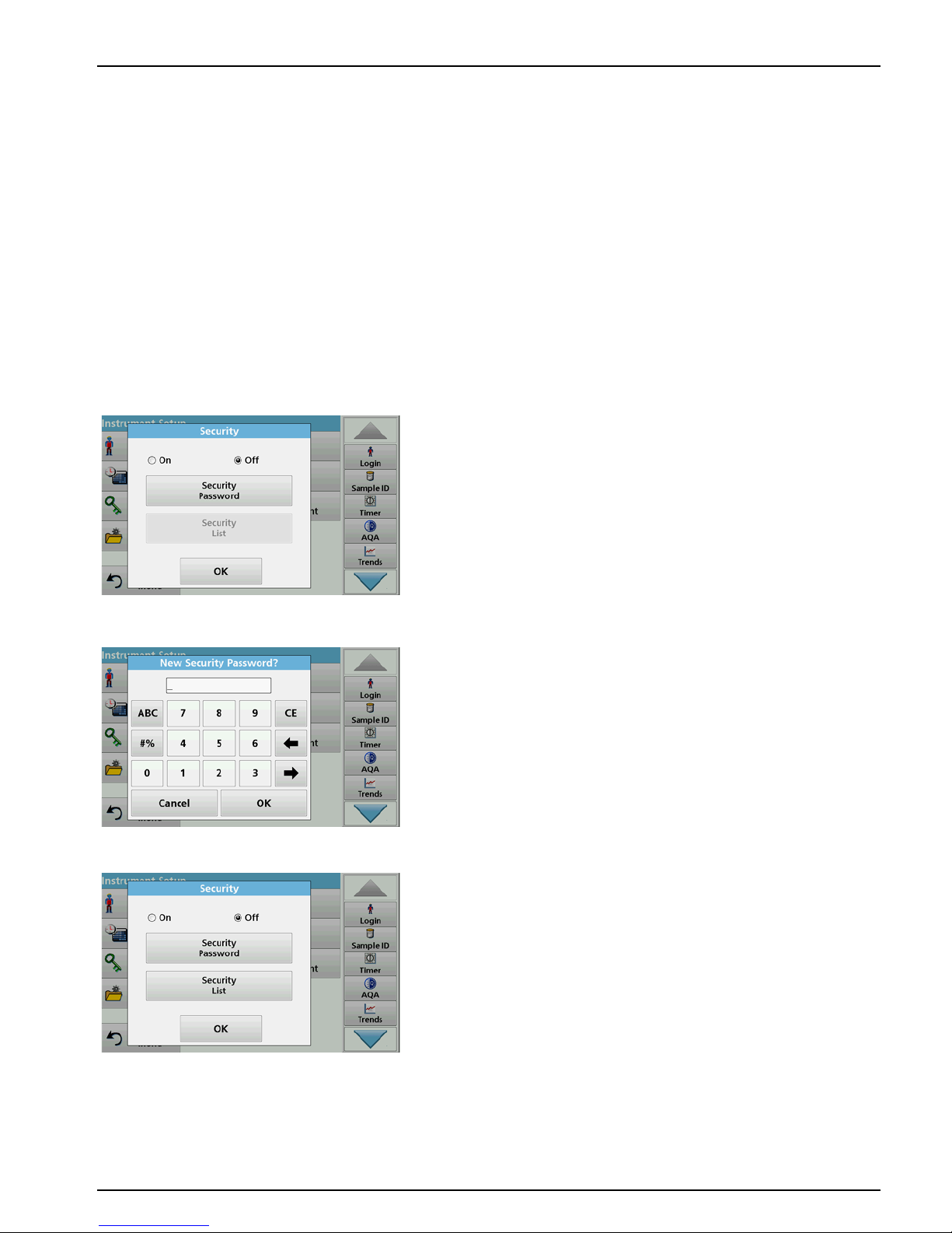
1. Press Security in the "Instrument Setup" menu.
2. In order to open the Security List, assign a password as
security administrator. Press Security Password.
3. Enter a new security password (up to 10 characters long) via
the alphanumeric keypad, and confirm with OK.
4. Press Security List to access various functions with security
level 1 or 2.
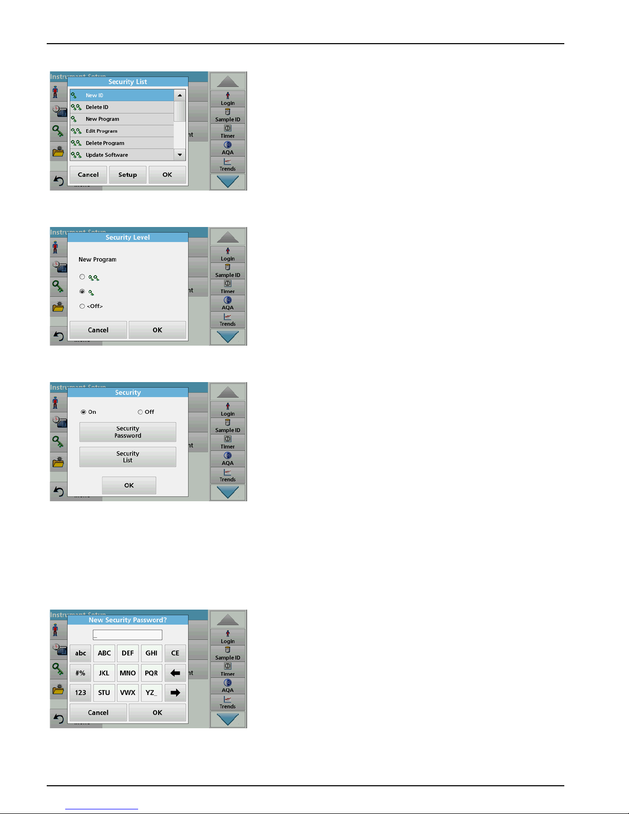
28
Standard programs
5. Select the required function and press Setup.
6. Select the required security level (two keys, one key or off)
and confirm using OK.
7. Press OK to return to the "Security" menu.
8. Press On to activate the new settings of the security list.
9. Press OK to return to the "Instrument Setup" menu.
Note: The alphanumeric keypad for entering the password appears
when a user tries to reach a locked setting.
5.2.3.1 Assign operator security level
Every operator with an operator ID can be assigned a security
level. This assignment is connected to the operator password.
Setup must be coordinated with the security administrator and
the operator.
1. Press Operator ID in "Instrument setup".
2. Enter the security password and confirm with OK.
3. Set up an operator ID (refer to section 5.2.1).
 Loading...