

Kodinis Raktas GN6Ib.U, GN6Ib.P, GN6Ib.UPS Installation Manual
VEHICLE ALARM SYSTEM 'GN6Ib'
Models 'GN6Ib.U', 'GN6Ib.P', 'GN6Ib.UPS'. Installlation manual.
1. SAFETY INFORMATION.
The 'GN6Ib' is a vehicle alarm system designed for use with cars with their original remote controlled central lock. The 'GN6Ib' (Fig. 1)can
be used in most cars (except cabriolets) with petrol or diesel engines, 12V batteries with the negative pole connected to "ground" (i.e. vehicle
body).
The vehicle alarm system must be installed inside the passenger compartment of the vehicle, in a place difficult to access in accordance with
the manufacturer's supplied wiring instructions.
The manufacturer of the alarm system recommends the following:
a) choose a qualified vehicle alarm systems installer to fit the device;
b) mount the system unit in place free from moisture and other elements that could pose to corrode the device. It should also be placed as far
away as possible from any heat emitting elements in the passenger compartment and sources of electromagnetic interference (e.g. vehicle
computer, fans, relay blocks);
c) avoid mounting the system unit directly onto metal parts of vehicle to prevent the accumulation of condensation in the system unit;
d) mount the system unit so that the wire connectors are going from the bottom side of the unit;
e) avoid placing wires next to moving or hot parts of vehicle;
f) don't overload the alarm system circuits, see the following circuit requirements:
cut - off circuit current ............................................................................... £ 25 A;
P
optional control circuit (OC) current ................................................. £ 0.13 A;
P
siren drive circuit current............................................................................ £ 2 A;
P
right direction indicator control circuit current ........................................ £ 7 A;
P
left direction indicator control circuit current .......................................... £ 7 A;
P
g) For EU countries only use settings compatible with EU directives.
2. ALARM SYSTEM INSTALLATION SEQUENCE.
a) select the system adaptation method to the central lock action sequence (see chapter 7);
b) install the system in accordance with the selected adaptation method and corresponding wiring diagram (see chapters 4, 5, 6);
c) progress through the system learning procedure (see chapter 7);
d) customize alarm system if default settings are not suitable (see chapters 3, 7);
e) fill out an installation certificate (see chapter 8).
3. PIN, FN, SN CODES.
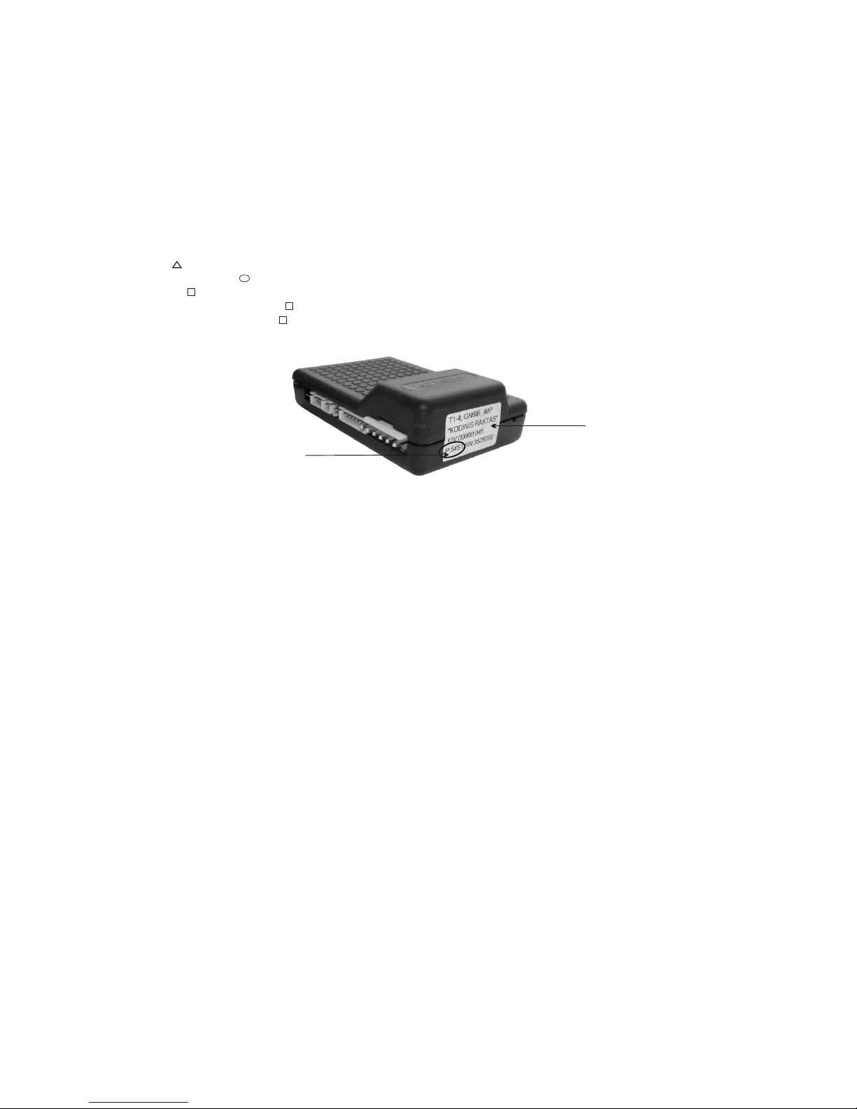
To enter the override and setup mode, to customize the alarm system according to the required security level the PIN, FN and SN codes are
required. The factory preset 4-digit PIN code is written on the alarm's 'system information' sticker (see Fig. 1). It is recommended that the PIN code
is changed after alarm system installed (N.B. remember the new PIN code by keeping a record of it in a file so it may be retained for future
reference).
3.1. THE OVERRIDE MODE.
The alarm system override mode is used in the following scenarios: if the remote control unit is lost; if the remote's battery becomes fully
discharged; if the car is being repaired. With this mode ON, the alarm system does not respond to the sensor as it is temporarily disabled, therefore
the following occurs as a result: the device will not immobilize the engine; the car will not become alarmed; the system's LED flashes frequently.
The override mode can be turned ON in two ways, by the use of the PIN code.
3.1.1. TURNING ON THE OVERRIDE MODE WITH THE HELP OF THE OVERRIDE BUTTON.
The most convenient way to turn the override mode ON is to enter the PIN code with the override button. If the override button is installed,
check your notes with alarm system's PIN, then press the override button as many times as the value of the first digit of the PIN (N.B. the time
between the presses should not exceed 1 second) and wait for a 1 second long LED flash which means that the first digit is entered. In the same
way enter the second, third and fourth digits of the PIN. Upon correct entry of all four digits of the PIN code the LED emits frequent flashes. If
you made a mistake while entering the PIN code, wait for a 1 second long LED flash, wait for 2 seconds and follow 3.1.1 all over again. If the
'anti-carjack' or immobilizer features are activated the system will respond to the first press of the override button as to the control of the
'anti-carjack' or immobilizer function. The system will respond to the next presses made as if the PIN code is being entered.
3.1.2. TURNING ON THE OVERRIDE MODE WITH THE IGNITION KEY.
If the override button is not installed, open the vehicle door and turn the ignition ON. After a short pause the system LED starts flashing
double flashes. Count these flashes until the number of double flashes (1 double flash = 1) corresponds with the first digit of the PIN code. Turn the
ignition OFF for a short time and turn it ON again. Count the double flashes until the number corresponds with the second digit of the PIN code.
Turn the ignition OFF and ON again. Enter the remaining two digits of the PIN code in the same way. Upon correct entry of all four digits of the
PIN code the LED emits frequent flashes. If you made a mistake while entering the PIN code, turn OFF the ignition, close the doors, and follow
3.1.2 all over again.
3.1.3. TURNING OFF (EXIT) THE OVERRIDE MODE.
Enter the PIN code and within 8 minutes of doing so enter the code '11' in a same way as PIN.
3.2. ALARM SYSTEM SETUP MODE.
The 'GN6Ib' features up to 85 system settings. Due to these settings the 'GN6Ib' can be adjusted to a particular vehicle or relevant customer's
requirements. The alarm system is supplied with the factory preset default settings listed in Table 2, chapter 8. If the default settings are not
suitable for the user you can customize them. To customize the alarm system please do the following steps:
a) turn override mode ON by entering the PIN appropriately;
b) within 8 minutes select the function (FN) which operation you want to change and enter the 2-digit FN code;
c) to change the function operation according to the new setting enter the 1-digit setting number (SN);
d) now exit setup mode by entering the code '11'.
For more details see chapter 7.
1
11
1
5
2
Fig. 1. 'GN6Ib' external view.
PIN code
Sticker

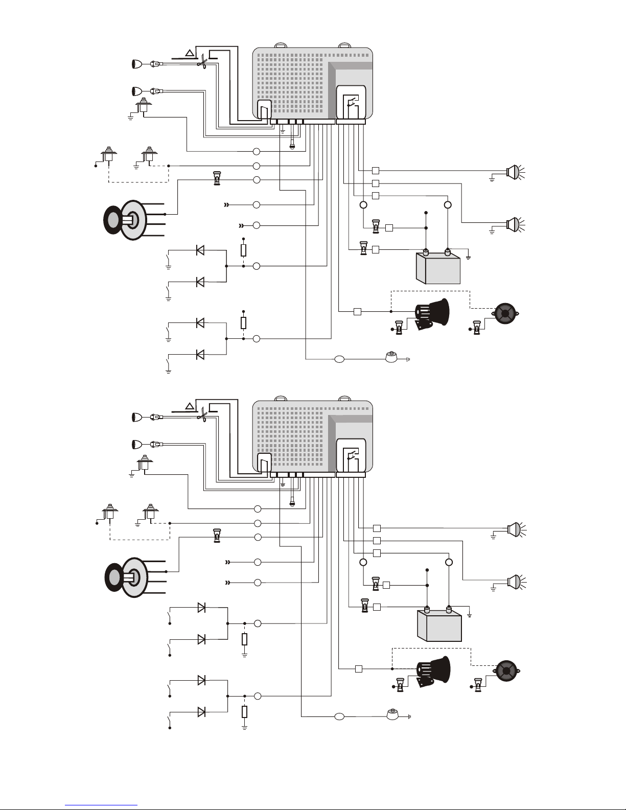
4. 'GN6Ib' WIRING DIAGRAM USING COMPUTER LEARNING OR AUTOMATIC LEARNING.
Fig. 2. 'Cadmin' software. Window 'OSC GN6IA'.
Grey
White
Brown
Black
Red
Blue
Yellow
Grey
Orange
Yellow
Black
Yellow
Red
“Ground”
+2
V
o
ys
1
f r
s te
m
Left direction
indicators
Right direction
indicators
Vehicle
battery
Ignition switch
Switch in the door strut,
luggage compartment, and / or
bonnet switch
5
8 5
8
87a87
a
878
7
3030
6
8 6
8
+12V
3A
I =130mA
max
+12V
+12V
P I N
AL
F
E
A
T
E
O T O
UR
A
C
O
D N
W
IT
H
C
R
I G
N 5 S
T
T
I
NGF = 4
E
E
O
V
R
RID
E
N
B
U
T
T
O
S =FN=5
4
,
N 2
AL F C I NOP
TIO
N U
N
T O
O
R
D
I
NG
H
ACC
WI
T
FN=51
TIN
G
SET
I
DE UOVER
R
B
T
T
O
N
S =FN=5
1
,
N 1
C
O
M
UN C
A
T
IO
N
T
W
I
H
'
GW1
M I S '
,
SN
=
7
F
N
=
5
1
UT
S
T
TER C
N
T
ROL
C
CUIT
C O
F
F AR O
I
R
F
,
S
N
N 51
=
2=
++
--
1
2
+
V
AC
C
ON
T
S
A R
T
I=7 A
max
55
44
33
22
11
--
++
15A
11
22
33
44
55
3A
66
5A
66
I=7 A
max
- -
+12 V
++
I=2 A
max
+ +
--
+12V
3A
3A
GSM
aerial
1 2 3 4 5 6 7 8 9
Contacts of Relays
K2
K1
GSW1
1 2
1 2 3 4 5 6 7 8 9 10 11 12 13
Red
Grey
Grey
Orange
Orange
Green
Green
Blue
Blue
C
O
N
D
I
TIO
N
2
F
=
4,
1
N 5
S
N
=
1
V
o
+
2
f
r
i
r
c
t
i n
n
d c
at
d e o i
i
o
r
s
7
7
-
-
DO
O
R
-
)S
(
F
N32,
S
=
2
N
S (+D
O
O
R
)
F
N=
N3
2,
S 1
Electronic siren
FN=65, SN=5
PULSE-LATCHER
3 2 1
+12 V
Horn type siren
FN=65, SN=1 - 4
i
C
Ad
m n
USB
C
T
I
O
O
N
DI
N
1
K
LOC
U
N
L
O
C
K
U
EL
C RP
L
S-ATHE
I
S C
N
N
E
C
T
ED
O
3
-P
I
C
N
E
C
T
OR
T
O
N
O
N
DURI G
NN
OM R
L
EARNIN
GC PUTE
3A
+12 V
K2
1 2 3 4 5 6
1 2
1 2 3
1 21 2
1 2 3 4 5 6 7
Contacts of
Relay K1
Ultrasonic sensor
(GN6Ib.SPU)
Ultrasonic sensor
(GN6Ib.SPU)
1
14V DC 25A max.
Cut off
circuit
1
Window 'OSC GN6IA'
The window shows real picture of control pulses that
alarm system regards as ARMING / DISARMING pulses
Main features:
l emulates 4 channel low speed oscilloscope;
l with 'PULSE-LATCHER' and 'GN6Ib' connected gives
real time picture of “what's going on” in the car;
l user friendly “step by step” interface;
l enable installer to set control pulses time, period and
phase tolerances;
l create data file for further usage in 'GN6Ib’;
l optional data file protection by password.
Note: latest version of 'Cadmin' software is available at web site: http://www.kodinis.lt/en/products/ACC
11
S
Y
T
E
M
L
E
DS
“Ground”
„Ground”
+
1
2
V
f
r
sy
t
e
m
os
V
s+12
f
or
s
y
t
e
m
Left direction
indicators
Left direction
indicators
Right direction
indicators
Right direction
indicators
Vehicle
battery
Vehicle
battery
Ignition switch
Ignition switch
Switches in the door strut,
luggage compartment and / or
bonnet switch
Switches in the door strut,
luggage compartment and / or
bonnet switch
O
ID
E
ON
V
E
R
R
BUTT
N=
1 N=
F
5
,
S
1
5. 'GN6Ib' WIRING DIAGRAM USING MANUAL LEARNING IN CASE OF LOW LOGIC LEVEL COMMUTATION.
6. 'GN6Ib' WIRING DIAGRAM USING MANUAL LEARNING IN CASE OF HIGH LOGIC LEVEL COMMUTATION.
++
++
--
--
+1
2
V
+
1
2V
C
A C
A
C
C
N
O
O
N
A
T
S
T
R
AT
ST
R
I=7 A
max
I=7 A
max
55
55
44
44
33
33
22
22
11
11
--
--
++
++
15A
15A
11
11
22
22
33
33
44
44
55
55
3A
3A
66
66
5A
5A
66
66
I=7 A
max
I=7 A
max
--
--
+12 V
++
+12 V
++
I=2 A
max
I=2 A
max
++
--
--
+12V
3A
3A
+1
2
f
o
dr c
t
i
o
n
V
r
i
e
i dc
t
o
r
n
i a s
o
i
1 V f r
ir
e
c
t n
+ 2
d
o
n ca
i
d
i o
r
s
t
-
-
-
-
R
-
DOO S
)
(
F
3
2,
SN=
2
N
O
R
-
D
O
S
)(
,
F
3
2
S
N
=
2
N
O
+
DO S
)
R
(
F
3
2
,
S
N=
1
N
O +
D
O S )
R (
F 32,
SN=
1
N
Electronic siren
FN=65, SN=5
+12 V
Horn type siren
FN=65, SN=1 - 4
Horn type siren
FN=65, SN=1 - 4
L
O
C
K
L
O
C
K
NLOCK
U
LOC
K
UN
From central
lock
actuator
From central
lock
actuator
66
66
77
ON
1
C D
I
TIO
N
O
N
1
C D
I
TIO
N
O
N
2
C
DIT
I
ON
+12 V
+12 V
+12 V
VD1
VD1
VD3
VD3
VD2
VD2
VD4
R1
3K - 10K
R1
3K - 10K
R2
3K - 10K
Door lock
contact
for locking
Door lock
contact
for locking
Door lock
contact
for unlocking
Central lock switch
contact in passenger
compartment
for locking
Central lock switch
contact in passenger
compartment
for locking
Central lock switch
contact in passenger
compartment
for unlocking
+12 V
++
+12V
3A 3A
+12 V
NO
I I
N 2
C
D
T
O
Door lock
contact
for unlocking
Electronic siren
FN65, SN=5
77
+12 V
VD4
O
R
I
DE T
O
NVE R B
U
T
F 1,
SN=
N5
1
R2
3K - 10K
Central lock switch
contact in passenger
compartment
for unlocking
11
+12 V
Note: Resistors R1, R2 are used, if logic levels on contacts of central lock switch in passenger compartment and door lock is alike in case the
central lock is locked and unlocked. Value is selected to get enough difference between levels and avoid induce disturbances in electronic
systems of vehicle.
+12 V
+12 V
Grey Grey
White White
Brown Brown
Black Black
Red Red
Blue Blue
Yellow Yellow
Grey Grey
Orange Orange
Yellow Yellow
Black Black
Yellow Yellow
Red Red
K2
K2
1 2 3 4 5 6
1 2 3 4 5 6
1 2
1 2
1 2 3
1 2 3
1 2
1 2
1 2
1 2
1 2 3 4 5 6 7
1 2 3 4 5 6 7
Contacts of
Relay K1
Contacts of
Relay K1
Contacts of
Relay K1
Ultrasonic sensor
(GN6Ib.SPU)
Ultrasonic sensor
(GN6Ib.SPU)
Ultrasonic sensor
(GN6Ib.SPU)
Ultrasonic sensor
(GN6Ib.SPU)
14V DC 25A max.
14V DC 25A max.
Cut off
circuit
Cut off
circuit
1
1
11
ST
S
Y E
M
E
L D
S
S
Y
T
E
M
E
L D
 Loading...