

Page 1
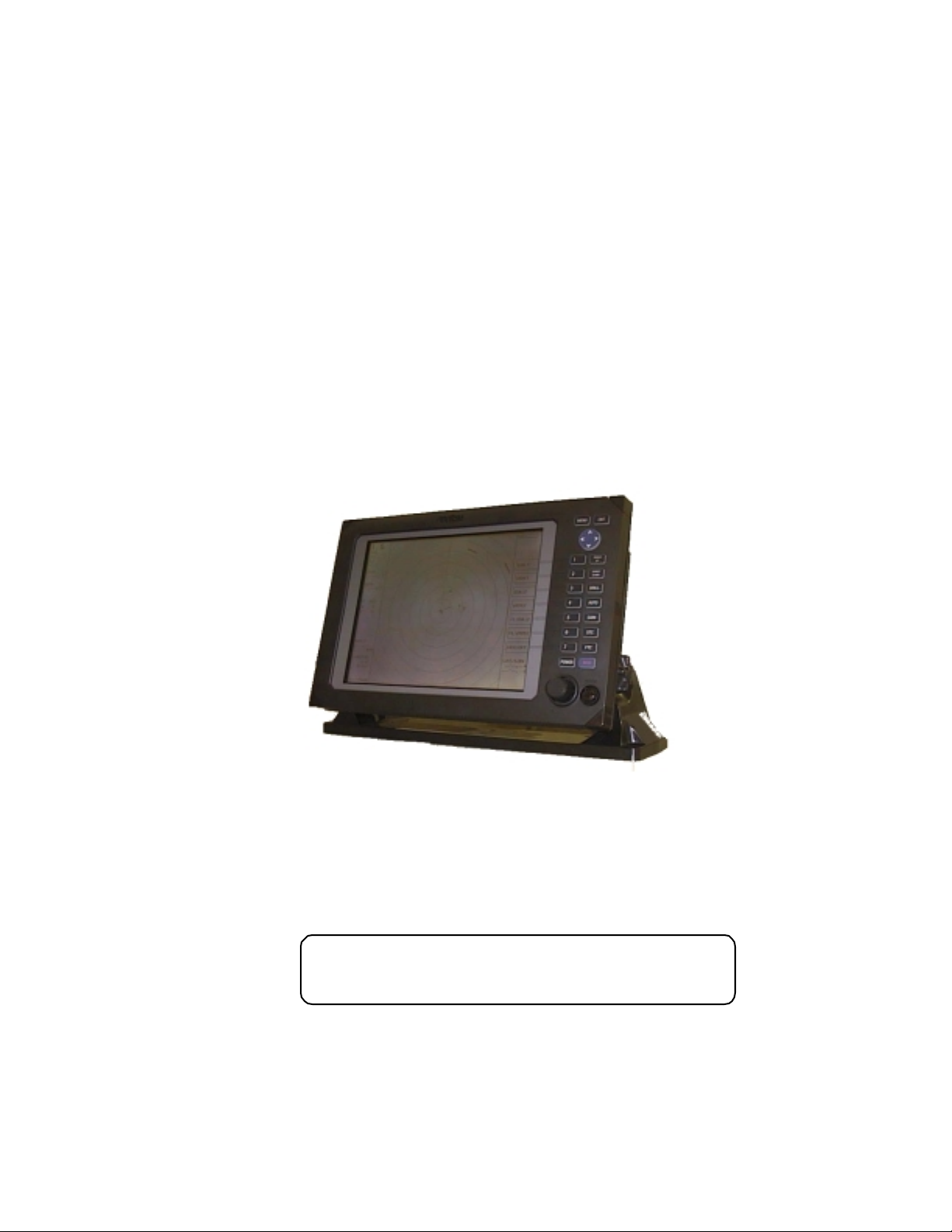
RA40C/RA41C/RA42C
Marine Radar
Instruction Manual
1st Edition
•
Read this manual before using the
equipment.
Page 2

Index
A
Adjustment
Distance............................... 75
Angle.................................... 75
Tuning .................................76
Antenna height.....................77
Automatic gain......................78
Automatic STC...................... 78
ALL PPI Screen ..............................64
ALL PPI/PPI Screen........................ 65
B
Bearing scale ................................. 26
Brightness..................................... 29
Brightness of Panel............... 29
Buzzer........................................... 71
C
Changing setting (CUSTOM)............68
Cont inual vari ab le range (VA R RNG) 38,50
Cou rse error (XTE)......................... 28
Cross cursor (+)..............................26
D
Display modes (MODE)...................38,52
E
EBL ............................................ 35,46
Bearing of EBL (EBL BRG)..... 71
Echo Menu.................................... 56
F
False echoe s.................................. 5
FL VRM, FL EBL ............................36,47
FTC ............................................33,57
G
Gain ............................................ 32,56
Guard zone (GZ)............................. 38,53
Guard zone mode (GZ MODE) 73
Guard zone level (GZ LVL)......73
H
Heading marker............................. 6
Heading Off (HDG OF F) ......... 38,49
Heading blink (HM FLSH)...... 71
Heading informatio n (H EAD) .. 28
Hold (HOLD) ..................................73
L
Language....................................... 73
M
Mark Line...................................... 51
Menu bar.......................................45
Man Over Board (MOB)................... 34
MOB Screen .................................. 65
Monitor operation (DISPLAY)........... 73
O
Off-center (OFF-C)..........................39,54
Option............................................87
P
Parallel cursor (///CSR)..................38,49
PPI Screen......................................62
PPI/NAV Screen .............................64
PPI/PPI Screen...............................63
PPI/SEMI3D Screen........................63
Pulse table (P TABLE)......................71
R
Radar interference..........................6
Radar screen ..................................26,27
Range............................................ 31
Range rings (RINGS)....................... 38,50
Range ring interval.................50
Reverse screen ...............................42,66
S
Semi-3D......................................... 43,63
Sleep (SLEEP).................................54
Speed (SPEED, SPD SET)................73
ST'BY ............................................29
ST'BY NAV screen...........................71
STC ............................................32,57
Stern marker (STERN M) .................71
Stretch (ST).................................... 41,58
Switching the screen (SEL WIN).......42,65
System check ................................66
T
Target (TARGET).............................51
Track (TRACK) ................................41,58
Tune ............................................40,57
Tune meter ...................................26
V
VAR RNG.......................................38,50
VRM ............................................35,47
Unit of VRM (RM UNIT)..........71
W
Way point (WAYP) ...........................28
Bear ing of Way p o int (WP BR G). .. 71
X
XTE ............................................28,44
Z
Zoom (ZOOM).................................41,59
N
Nav (Navigation) Menu.................... 52
Navigation screen........................... 28
North mark (NORTH M) .................. 6,71
Page 3
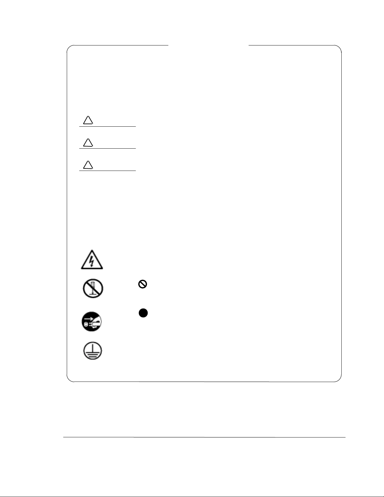
Safety Symbols
To prevent the risk of personal injury or damage to the equipment, the following
safety symbols are used to indicate saf ety- related information. Ins ure that you clearly
understand the meanings of the symbols BEFORE using the equipment.
Symbols Used in M anual
!
DANGER
WARNING
!
CAUTION
!
This indicates a very dangerous proced ure that could r esult
in serious injury or death if not perfor med properly.
This indicates a hazardous procedure that could result in
serious injury or deat h if not performed proper ly.
This indicates a hazardo us proced ure or danger that could
result in light-to-severe injury, or that might damage the
equipment, if pr oper precautio ns are not taken.
Safety Symb ols Used on Equipment
The following safet y symbols are used inside or on the eq uipme nt near oper atio n locations to provide information about safety items and operation precautions. Insure
that you clearly underst and the meani ngs of the sy mbols and t ake the necessary pr ecautions BEFORE using t he equipme nt.
This indicates high voltages with a risk of ser ious electric shock if the part
is touched. NEVER touch the part with bare hands, etc.
The symbol prohibits the operatio n shown inside the symbol. (The example in the left prohibits disassembly. )
The symbol indicates t hat the operat io n inside t he sy m bol is potentially
hazardous. (T he example o n the left indicates that the pl ug should be held
when disconnecting it from the AC outlet.)
This indicates the ground (earth) terminal. If the equipment cannot be
grounded via the power cord, connect this terminal to ground. T here is a
risk of ser ious electric shock if the equipment is not grounded.
RA40C/RA41C/RA42C
Marine Radar
Instruction Manual
21st Jul. 2000 (1st Edition)
Document: E-A40C/41C/42C-2-00
i
Page 4
y
•
For Safet
•
WARNING / • •
DO NOT OPEN THE COVER EXCEPT SERVICE
•
PERSONNEL. YOU MAY GET AN ELECTRIC SHOCK.
SWITCH OFF SHIPS MAIN AND PULL OFF MOTOR
•
FUSE BEFORE MAINTENANCE.
ROTATING ANTENNA MAY HIT YOU.
KEEP OFF DURING TRANSM ISSION.
•
RADIATION LEVEL: 100W/m2 DISTANCE : 0.8m
RADIATION LEVEL: 10W/m2 DISTANCE : 8m
DO NOT DROP COVER.
•
IT MAY HIT SO MEBODY.
•
•
DO NOT PAINT THE RADOME.
•
PERFORMANCE WILL DOWN.
CAUTION / • •
•
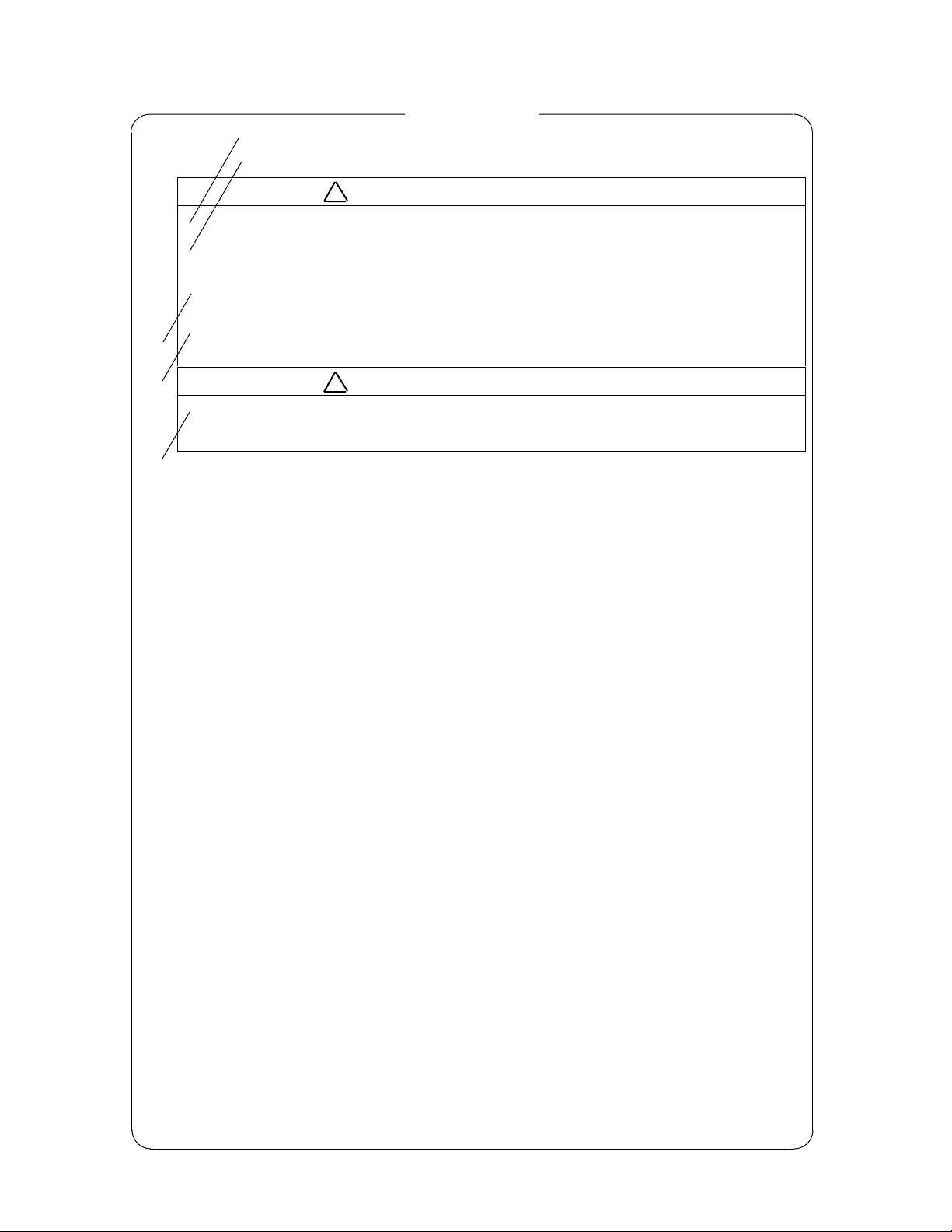
WARNING and CAUTIO N for Scanner Unit and Antenna ;
!
There is a ris k o f recei ving elect ric s hock if t hese parts are touched by
accident. Only qualified personnel should remove covers on these
parts.
"
To avoid accidental antenna ro tation, tur n off ship’s mai n and pull off
out the motor fuse du ring repair inspect, or maintenance.
When repairi ng or i nspecti ng the sca nner unit wear a safety har ness
and provide a secure platform so that there is no danger of falling even
when t he vessel list s o r whe n t here is an une xpect ed incide nt s uc h as
an earth quake.
• ••••••••••••••••••••••
•••••••••••••
• ••••••••••••••••••••••••
••••••••
•••••••••••••••••••••••••
• •••••••••••••••
: 100W/m
•••••
: 10W/m
•••••
• ••••••••••••••••••
•••••••••••
• ••••••••••••••••••••
••••••••
2
•• : 0.8m
2
•• : 8m
#
Do not approach the antenna while it is transmitting.
In additio n, at inspection never loo k into the wave g uide d uring tr ansmission.
$
When remo ve the s canner co ver etc. , do not dro p it. It may e ndanger
people below.
%
Do not paint the RADOME. Antenna performance will be down.
ii
Page 5
•
SEE INST RUCTION MANUALS BEFORE
•
•
•
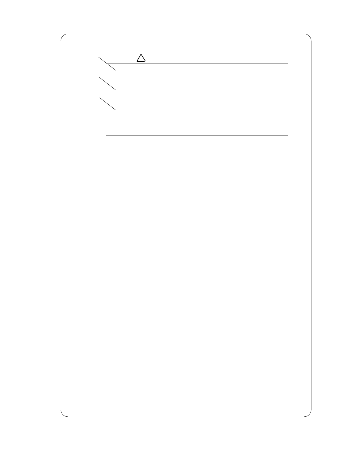
WARNING for Display Unit ;
!
See instruction manuals before connecting power. Safety information is
CONNECTING POWER.
SAFET Y INFOR MATIO N IS WRITT EN IN.
EARTH CONNECTION ESSENTIAL
•
BEFORE CONNECTING POWER.
YOU MA Y GET AN ELECT RIC SHOCK.
DO NOT OPEN THE COVER E XCEPT
•
SERVICE PERSON NEL.
HIGH VOLTAG E IS INSIDE.
YOU MA Y GET AN ELECT RIC SHOCK.
WARNING / • •
• •••••••••••••
••••••••••••
••••••••••••••
• ••••••••••••••
•••••••••
••••••••••••
• •••••••••••••
••••••••••
••••••••••••••
••••••
written in.
"
Earth connection essential before connecting supply.
There is a risk of serious electric shock if the equipment is not
grounded.
#
There is a ris k o f recei ving elect ric s hock if t hese parts are touched by
accident.
Only qualified personnel should remove covers on these parts.
iii
Page 6

Installation
Radio laws dictate t hat this radar may only be installed by properly licensed perso nnel.
Licensing
You must obtain a license as prescribed by t he Radio Law to operat e this unit.
To Customers
* To use this equipment effect ively, t he oper ation and mainte nance pr ocedure i n t his manual
must be followed proper ly. Note that this equipment is only a navigational instr ument having no warrant for navigation safety. Non-execution of fundamental navigation requirements such as the ship location check or lookout is not allowed.
* If some abnormality occurs in this equipment, im mediately tur n off the equipment POWER
switch and the radar main switch in the power distribution board and notify our maintenance section or dealer.
* This instrument uses oscillator and LCD backlight. They are easy to be broken. Do not
subject the instrume nt to excessive for ce or dr op it.
* The mercury ( Hg) is used in LCD backlight. W hen you discard your radar, it is due to laws
or regulations of your natio ns.
iv
Page 7

Contents
For sa fe t y
CHAPTER 1 OVERVIEW ....................................................................1
1.1 Introduction.................................................................................................1
1.2 Organization of This Manual.......................................................................1
CHAPTER 2 USING RADAR FOR THE FIRST TIME.............................. 2
2.1 What is a radar ? .........................................................................................2
2.2 Characteristics of Radar Wave ....................................................................3
2.3 Terms Specific to Radars.............................................................................6
CHAPTER 3 INSTALLATION...............................................................10
3.1 Checking Contents of Your Package...........................................................10
3.2 Checking Power Supply Voltage..................................................................11
3.2.1 Power Supply Requirement....................................................................12
3.2.2 Fuse Replacement ..................................................................................12
3.3 Determining Place of Installation................................................................12
3.3.1 Scanner unit...........................................................................................12
3.3.2 Display unit ............................................................................................12
3.3.3 Shifting away from obstacles.................................................................13
3.4 Installing Scanner Unit ...............................................................................14
3.5 Installing Antenna Unit...............................................................................15
3.6 Installing Display Unit.................................................................................16
3.7 Connecting Cables.......................................................................................17
3.7.0 Interconnecting cable (RA40C Radome
scanner)............................................17
3.7.1 Interconnecting cable (RA41C Radome scanner) ..................................17
3.7.2 Interconnecting cable (RA42C Open scanner).......................................20
3.7.3 Grounding wire.......................................................................................21
3.7.4 Power supply cable.................................................................................22
3.8 Adjustment ..................................................................................................22
3.9 Connecting External Equipment to Display Unit .......................................23
3.10 Countermeasure for Electromagnetic Interference ..................................23
3.11 When Discarding Your Radar....................................................................24
CHAPTER 4 FUNCTIONS AND NAMES ...............................................25
4.1 Key layout ....................................................................................................25
4.2 Rear panel....................................................................................................26
4.3 Radar screen (Single screen).......................................................................26
4.4 Radar screen (Dual screen) .........................................................................27
4.5 Radar screen (All PPI screen) ......................................................................27
4.6 Radar screen (All PPI/PPI screen) ...............................................................28
4.7 Navigation screen ........................................................................................ 28
CHAPTER 5 OPERATION...................................................................29
Basic operation of Radar ...................................................................................29
5.1 Powering On and Off....................................................................................29
5.2 Adjusting brilliance of screen and key-backlight........................................29
5.3 Basic Operations .........................................................................................30
Page 8

5.3.1 Powering On and Off...............................................................................30
5.3.2 Transmitting ...........................................................................................30
5.3.3 Adjusting brilliance of screen and key-backlight...................................31
5.3.4 Changing Distance Range (RANGE UP, RANGE DOWN).......................31
5.3.5 Automatic adjustment (AUTO) ...............................................................31
5.3.6 Sensitivity adjustment (GAIN) ................................................................32
5.3.7 Removing sea clutter (STC)..................................................................... 32
5.3.8 Removing rain and snow clutter (FTC)...................................................33
5.3.9 Man Over Board (MOB) ..........................................................................34
5.4 Fu nct i on s of Soft Ke y s.................................................................................35
5.4.1 Bearing measurement (EBL1).................................................................35
5.4.2 Bearing measurement (EBL2).................................................................35
5.4.3 Distance measurement (VRM1)..............................................................35
5.4.4 Distance measurement (VRM2)..............................................................36
5.4.5 Measuring the angle between two points (FL EBL2)..............................36
5.4.6 Measuring the distance between two points (FL VRM2)........................36
5.4.7 Changing the group of Soft Keys(NEXT).................................................37
5.4.8 Erasing heading maker temporarily (HDG OFF)....................................38
5.4.9 Using parallel cursors (///CSR).............................................................38
5.4.10 Establishment of the indication of the RANGE RINGS (RINGS)..........38
5.4.11 ON/OFF of variable range function (VAR RNG) ...................................38
5.4.12 Changing display modes (MODE).........................................................38
5.4.13 Guard Zone (GZ) ...................................................................................38
5.4.14 Off Center (OFF-C)................................................................................39
5.4.15 Setting of the SLEEP function(SLEEP).................................................40
5.4.16 Tuning adjustment (TUNE)...................................................................40
5.4.17 Echo expansion (ST) .............................................................................41
5.4.18 Displaying locus of target (TRACK) ......................................................41
5.4.19 Enlarging selected areas (ZOOM).........................................................41
5.4.20 Increasing sensitivity (S/L)...................................................................42
5.4.21 Switching the screen (SEL WIN)...........................................................42
5.4.22 Changing the color of screen (PICTURE)..............................................42
5.4.23 Change to PPI screen (PPI)....................................................................43
5.4.24 Change to SEMI3D/PPI screen (SEMI3D)............................................43
5.4.25 Change to PPI/PPI screen (PPI/PPI).....................................................43
5.4.26 Change to PPI/NAV screen (PPI/NAV) .................................................44
5.4.27 Change to ALL PPI screen (ALL PPI).....................................................44
5.4.28 Change to ALL PPI/PPI screen (ALL PPI2)............................................44
5.5 MENU Operation..........................................................................................45
List of MENU.................................................................................................45
-
5.5.1 Mark Menu..............................................................................................46
5.5.1.1 Bearing measurement (EBL1) ............................................................46
5.5.1.2 Determining the distance (VRM1) ......................................................47
5.5.1.3 Bearing measurement (EBL2) ............................................................47
5.5.1.4 Determining the distance (VRM2) ......................................................47
5.5.1.5 Measuring the distance or angle between two points ( FL EBL2, FL VRM2 )
....................................47
5.5.1.6 Measuring the angle between two points (FL EBL2)..........................48
5.5.1.7 Erasing heading maker temporarily (HDG OFF) ...............................49
5.5.1.8 Using parallel cursors (///CSR) ........................................................49
5.5.1.9 Establishment of the indication of the RANGE RINGS (RINGS) .......50
5.5.1.10 Variable range function ( VAR RNG )...............................................50
5.5.1. 11
5.5.1.12
Output the position data of Cursor (TARGET).................................51
Follow the Distance and Bearing marker on the cursor (+MK LINE) 51
Page 9

5.5.2 Nav (Navigation) Menu ............................................................................52
5.5.2.1 Changing display mode (MODE)....................................................... 52
5.5.2.2 Guard Zone (GZ) ................................................................................53
5.5.2.3 Shifting display in specific direction (OFF-C)....................................54
5.5.2.4 Setting of the SLEEP function(SLEEP) ..............................................54
5.5.3 Echo Menu................................................................................................56
5.5.3.1 Sensibility adjustment (GAIN) ...........................................................56
5.5.3.2 Removing sea clutter (STC)................................................................57
5.5.3.3 Removing rain and snow clutter (FTC)..............................................57
5.5.3.4 Adjusting receiver tuning (TUNE)......................................................57
5.5.3.5 Echo expansion (ST)...........................................................................58
5.5.3.6 Displaying locus of target (TRACK)....................................................58
5.5.3.7 Enlarging selected areas (ZOOM) ......................................................59
5.5.3.8 Increasing sensitivity (S/L) ................................................................60
5.5.4 SETUP Menu ..........................................................................................61
5.5.4.1 Initiating the screen display (WINDOW)............................................61
- Limitation of screen operation.....................................................................62
- Screen modes and Operations.....................................................................62
(a) PPI Screen .........................................................................................62
(b) PPI/SEMI3D Screen..........................................................................63
(c) PPI/PPI Screen ..................................................................................63
(d) PPI/NAV Screen ................................................................................ 64
(e) ALL PPI Screen ..................................................................................64
(f) ALL PPI/PPI Screen............................................................................65
(g) MOB Screen.......................................................................................65
5.5.4.2 Switching screens on PPI/PPI screen (SEL WIN) ..............................65
5.5.4.3 Changing the color of screen (PICTURE) ...........................................66
5.5.4.4 Fault Diagnosis by Self Check (SYSTEM CHECK).............................66
5.5.4.5 Changing the content of the setting (CUSTOM) ................................68
5.5.4.5.1 Changing the settings of soft keys (KEY ASSIGN).........................69
5.5.4.5.2 Changing the content of settings 1(PRESET1)..............................71
5.5.4.5.3 Changing the content of settings 2 (PRESET2).............................73
5.5.4.5.4 Changing the content of settings (ADJUSTMENT).........................75
(1) Adjusting distance (TIMING ADJ) ...................................................75
(2) Adjusting angle (HEAD ADJ)...........................................................75
(3) Adjusting tuning circuit (TUNING CAL) ..........................................76
(4) Adjusting antenna height (ANTENNA).............................................77
(5) Setting GAIN circuit (GAIN).............................................................78
(6) Setting STC circuit (STC).................................................................78
CHAPTER 6 MAINTENANCE AND INSPECTION...................................79
CHAPTER 7 TROUBLESHOOTING......................................................81
7.1 Fault Diagnosis by Self-check.....................................................................81
7.2 I nspect i ng Each Pa r t ...................................................................................82
CHAPTER 8 PRODUCT SPECIFICATIONS...........................................83
8.1 General..........................................................................................................83
8.2 Scanner Unit.................................................................................................85
8.3 Display Unit ..................................................................................................85
Page 10

8.4 Extern a l I n te r fa ce ........................................................................................ 86
8.5 Standard set................................................................................................. 87
8.6 Options......................................................................................................... 87
8.7 External dimensions and weight .................................................................87
8.8 External connection and function ...............................................................87
APPENDIX
1. RA40C GENERAL SYSTEM DIAGRAM
2. RA41C GENERAL SYSTEM DIAGRAM
3. RA42C GENERAL SYSTEM DIAGRAM
4. RA40C INTERCONNECTION DIAGRAM
5. RA41C/42C INTERCONNECTION DIAGRAM
6. OUTLINE DR AWING DISPLAY UNIT
7. RA40C OUTLINE DRAWING SCANNER UNIT
8. RA41C OUTLINE DRAWING SCANNER UNIT
9. RA42C OUTLINE DRAWING SCANNER UNIT
10. FLUSH MOUNT PROCEDURE
11. INDEX
RA40C TEMPLATE OF SCANNER MOUNTING HOLES (ACTUAL SIZE)
RA41C TEMPLATE OF SCANNER MOUNTING HOLES (ACTUAL SIZE)
Page 11

CHAPTER 1 OVERVIEW
1.1 Introduction
The RA40C/41C/42C represents a compact, high-performance color marine radar
tha t del ivers a peak pow er ou tput of 2 kW(RA 40C) or 4 kW (RA41C /42C) fro m t he antenna and uses an 10-inch color liquid crystal display.
In addition to a microcomputer, it incorporates a video signal processing LSI and a
new ly deve lope d LSI chi p excl usiv e ly de sign ed for ra dars, t hu s prov idin g v e rsa til e functionality and h i gh p erf o rmance.
Features
1. A thin display unit incorporating a liquid crystal display.
2. E as y op er at i on usi ng o nly a few k ey s and m enu screen s.
3. A positi on of key and its functi on ca n be se t i n po siti on ( Sel ect abl e soft function key).
4. Easy operation by the rotary knob.
Gain, STC, FTC, EBLs, VRMs etc. can be controlled by the rotary knob.
5. A sh ort and a long range ech o can be seen at a ti me ( D ual range rad ar) .
6. S em i -3 D screen d isp l a y fo r easy i den t i fi cati on of targ et s in n oise.
7. Capable of continuous distance range changes (Continual variable range).
8. Waterproof construction of display allows installation at any desired location.
1.2 Organization of This Manual
This manual provides a wide range of information necessary to operate the
RA40C/41C/42C
radar ranging from the basic knowledge on radars to the methods of operating, installing,
and maintaining the radar. T he manua l also provide s rat her detaile d t e chnical informatio n o n how t o ad jus t vi deo di splay to ob t ain clear i mages. Y ou are r eq uest ed to read thi s
manual thoroughly from beginning to end in order to understand the various functions of
the radar so you can take full advantage of its advanced functions. If you are using a
radar for th e fi rs t time, refer to the bas i c data on rad ars in CH APTE R 2.
This manual consists of the following chapters:
USING RADAR FOR THE FIRST TIME ...................... CHAPTER 2
I N STALLATION ........ ..... ..... ... . CHA PTER 3
FUNCTIONS AND NAMES ...................... CHAPTER 4
OP ERATION ........ ..... ..... ... . CHA PTER 5
INSPECTION AND MAINTENANCE ...................... CHAPTER 6
TROUBLESHOOTING ...................... CHAPTER 7
PRODUCT SPECIFICATIONS ...................... CHAPTER 8
I f you are an e x pe r i ence d u ser of r a dars, skip C H A PTER 2 and begi n fr om C H A PTER
3.
1
Page 12
CHAPTER 2. USING RADAR FOR
THE FIRST TIME
This chapt er descr ibe s ba sic i nfor mat ion o n r ada rs a nd expl ain s t echni cal t e rms u sed
in radar operation fo r th o s e who is usi n g a radar for the f irst time.
2.1 W hat is a radar ?
A marine radar is one of the navigation equipment installed on a ship. I t emits a radio
wave in very high frequency called a microwave from its antenna and receives the reflected
ra dio wa ve fr o m obj e cts o n t he se a ( e.g., o t her ships, bu oy s, a nd la nds). The rece i ve d r a di o
wave is converte d into an electric signal which is displaye d on a display scree n to indicate
the presence of such obj ect s. Alt h ou g h it is ve r y di fficu l t t o find ot h e r sh ips o r t he de stination coast with human eyes at night or in thick fog, a radar helps you detect objects on the
sea helping you av oid danger when sailing. The ante nna turns 360 degre es a s it radiate s
waves , allowin g y o u to gras p ambi en t co ndi ti ons aro und your shi p at a glan ce.
The radio wave r adi ated f r om th e anten na i s c a l led a pul se wave a nd the rada r per fo r ms
transmission and reception alternately. Several hundred to several thousand pulse waves
gener al l y are tran sm i tted whi l e the an tenn a r o tates o ne turn.
Other ship
Buoy
Rad a r wav e
Rad a r dis p lay
Your ship
Antenna (Rotating)
Fig .2-1 What is a radar?
Antenna
There are many types of antennas generally used for a
radar. For example, these include a parabolic antenna and
a slotted-array antenna. The performance of the antenna
determines that of the radar. The dominant factors are the
antenna's beam width and side lobe level. The narrower
the beam width, the higher the resolution of the angle
direction. The lower the side lobe level, the fewer the effect
of a f a l se echo.
Side lobe
A beam in one direction in which the strongest
radio wave is radiated from the antenna is called the
main lobe and beams in other directions are called
"side lobes". The side lobe level refers to the difference in level between the largest side lobe and the
main lobe.
Side lobe
level
Fig.2-2 Antenn a pattern
Beam width
Main bea m
Side lobe
Antenna
2
Page 13

Beam w i dth
A bea m widt h is defi ned as the widt h of t he ma i n l obe a t a n a n g le w here t he radi ated power is halved as measured from the position from which the strongest radio
wave is rad i ated .
2.2 Ch aracteri st ics of Radar Wave
Radio wave s from the radar propagat e while bending slightly along the te rrestrial surface. This characteristic varies dependent on the density of the atmospheric air. The sight
distance D of a ra dar ge ne ra lly is said to be approximate ly 6% longer than t he optical sight
distance and is calculated using the equation below :
D (NM) = 2.22 ( h1 + h2 ) where, h1= antenna height in meters
h2= target height in meters
Line of sight
Radar Ra d io
Wave
h1 h2
Earth
Fig.2-3 Ra dar w ave
Targets difficult to display on screen
The intensity of the reflected wave from a target depends on the distance, height,
and size of the target, as well as its material and shape. Targets constructed with
FR P, w ood, or oth er l ow- r eflectanc e ma ter ials o r tho se th a t have a smal l inci den t ang le
are difficult to display on a screen. Therefore, FRP and wooden ships, sandy beaches,
and sandy or muddy shallows all are difficult to catch and require attention when
m onito r i ng on t he s creen. Espec iall y , coa st l i nes o n th e r adar image ap pear to be pr esent mo r e ap ar t from th e shi p th an they are actuall y l o cat ed. Theref ore, i t i s importan t
no t to misint er pret t he a va i lable d a ta .
Invisible
Apparent coastline
3
1
HU
Visible
Actual(invisible)
coastline
Fig.2-4 Targets difficult to display on screen
Shadow zon es of r adar
Radar waves are characteristic in that they propagate straight ahead. Therefore,
if the ship's smokestack or mast is locate d nea r t he a ntenna or the re is a ta ll ship or
mount a i n at the side of the s h ip, su ch a n object g ene r at es a shadow be h in d it. In t hi s
3
Page 14
case, some objects produce a complete shadow and some produce a partial shadow. In
an extreme case, the shadow of an object may extend to a position far away and cannot be displayed on the screen at all. Since these shadows can be discovered when installing an antenna, the problem can be a v oided by changing t he place of ante nna insta l lat io n t o minimiz e t he sha dow. Ta r g e ts in sh a dow z o nes a r e di fficu l t t o displa y on
the sc r een.
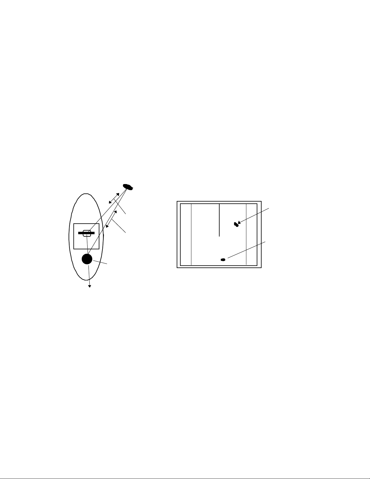
Fal s e echoes
A false echo of an actually nonexistent object may sometimes appear on the
screen when sailing. The following explains the cause of each of such phenomena.
A. Ghost echoes
It somet ime s h a ppe ns tha t on e l a r g e obj e ct ne ar the sh ip appe a r s at tw o di ffe r ent
bear ing s. One is th e actua l ech o an d o t her i s a g ho st echo g enerated as t he wave is rereflected from the ship's own smokestack or mast. The former appears at the correct
distance and bearing on the screen and the latter appears behind the smokestack or
mast. This type of false echo is also gener ated by re -reflection of wave s from bridges
and quay walls other than the ship itself.
Target
Direct reflec tion
path
3
1
HU
Real echo
Secondary
reflection path
Ghost echo
Mast etc.
Direction of ghost echo
Fig.2-5 False echoes of radar (Ghost echoes)
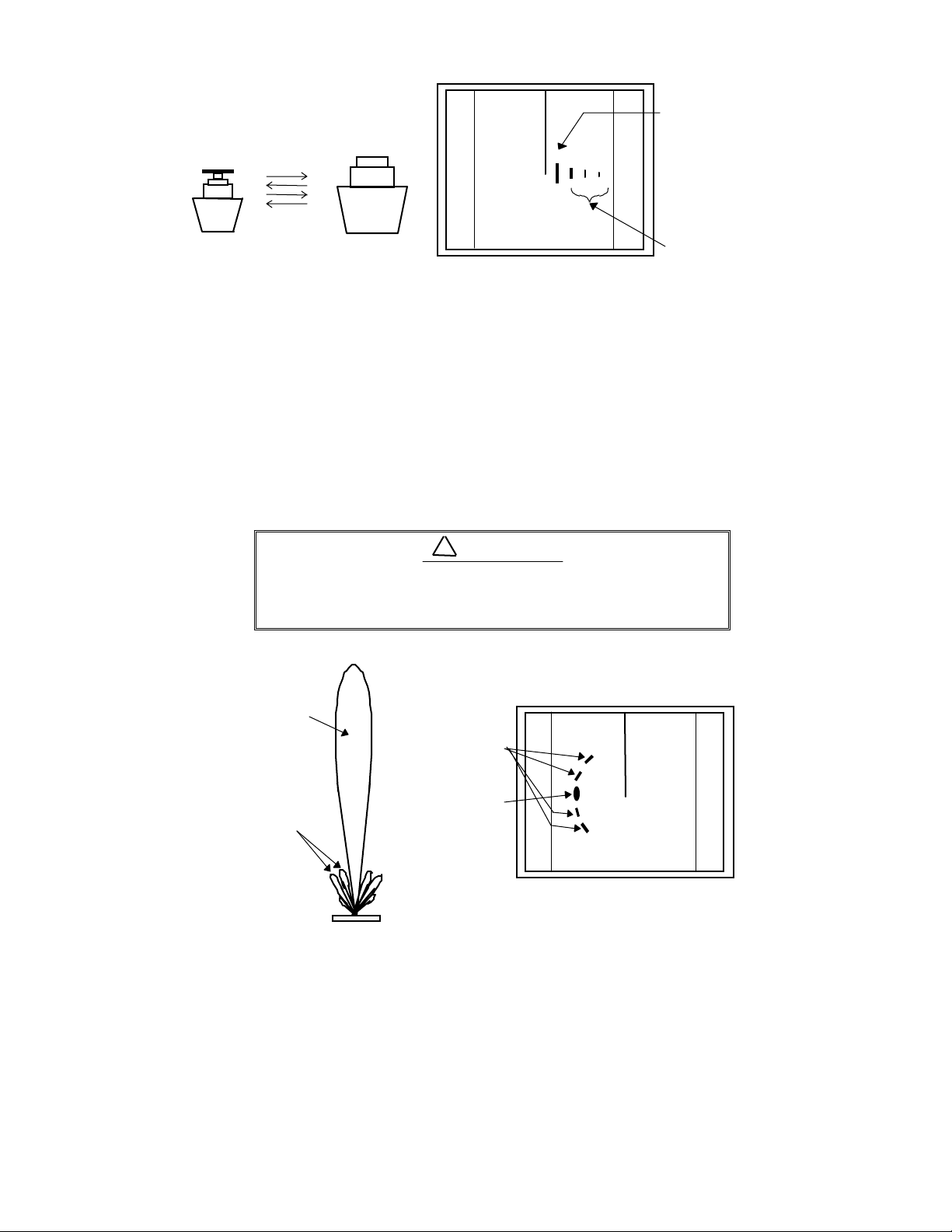
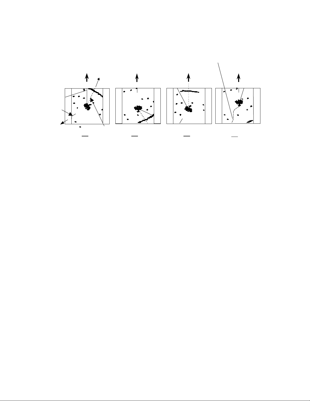
B. Multiple echoes
If th ere i s a l a r g e verti cal r eflecti ng plane n ear the ship as in the cas e when your
ship passes alongside a large ship, the wave is repeatedly re flected back and forth
between your ship and the other object. For this reason, two to four images appear on
the screen at equal intervals in the same bea ring. A false echo that is genera ted by
such multiple reflections is called multiple echoes. In this case, an image appearing at
the nearest position is the real echo. Multiple echoes disappear as the ship moves
away from the refle cting object or its bear ing change s. Ther e fore, it is n ot difficult to
deter mine the co r r ect i mag e.
4
Page 15
3
1
HU
Real echo
Multiple
echoes
Fi g.2-6 False echoes of rada r (Mult iple ec hoes)
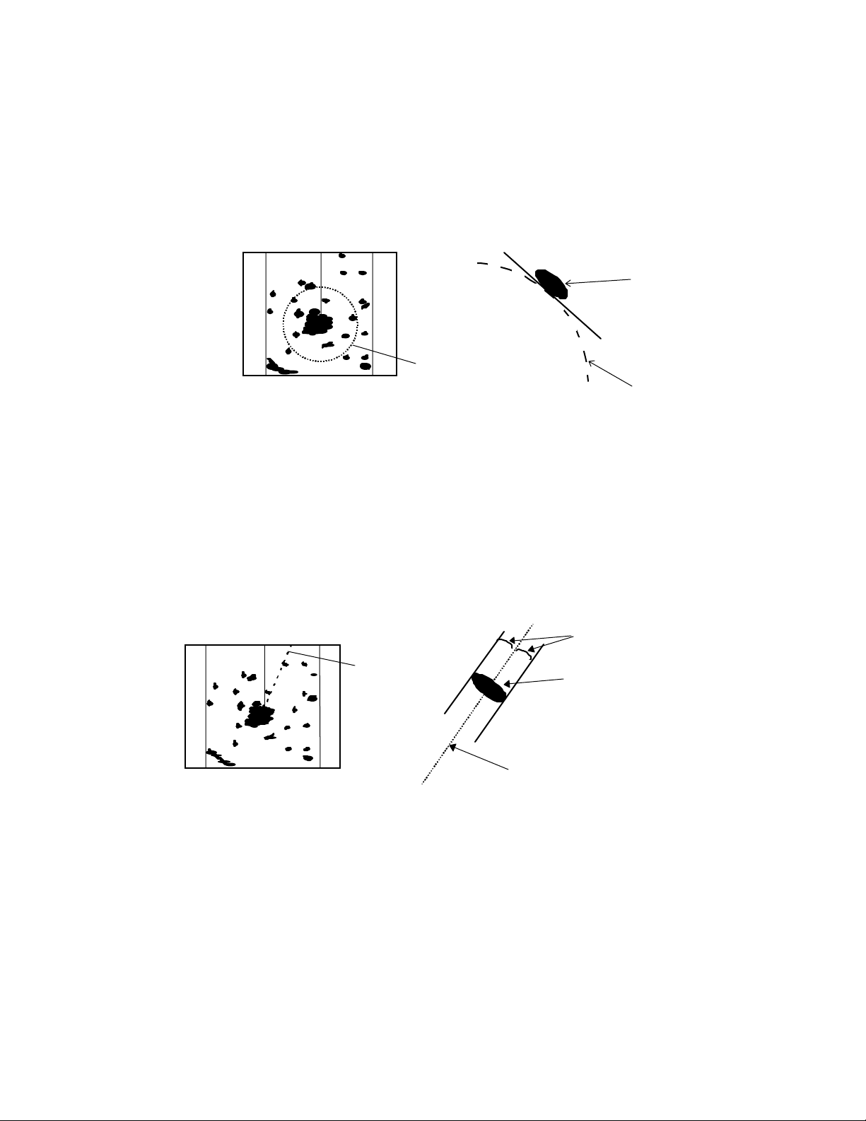
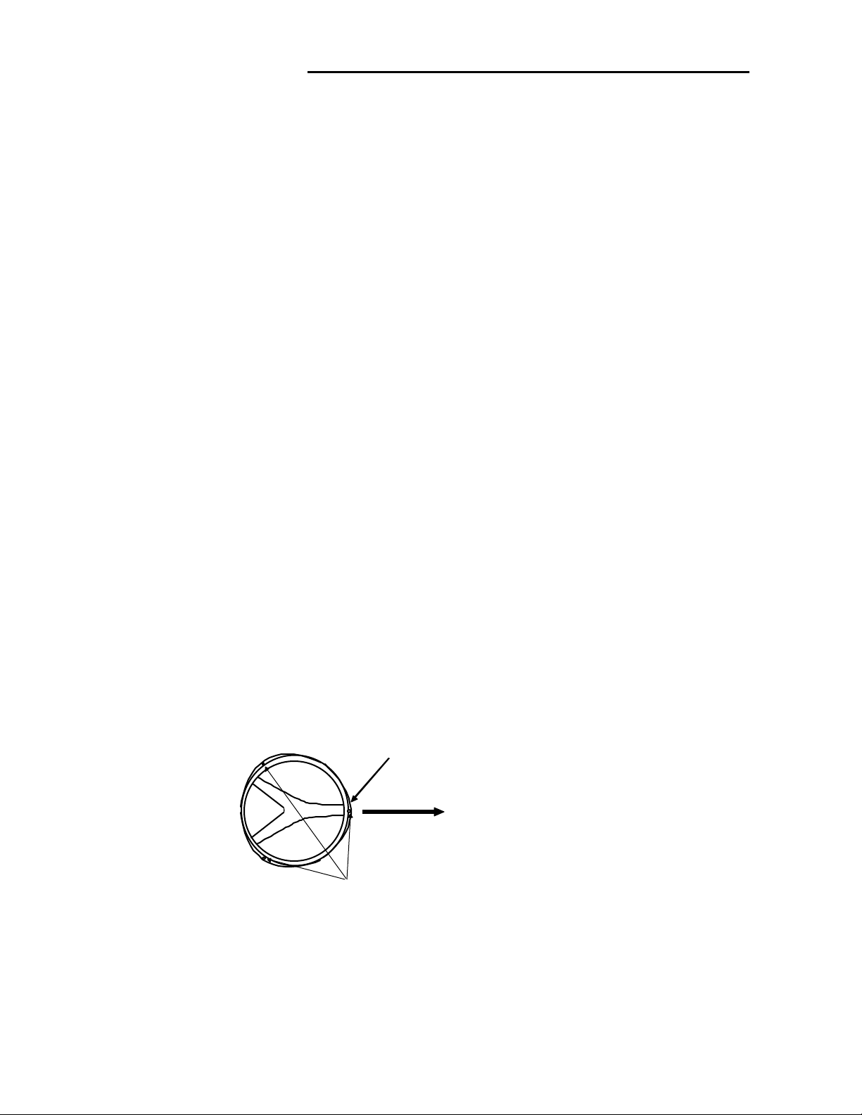
C. False echoes caused by side lobe
The radiant beam emitted from an antenna contains side lobes in directions other
than th a t of t he main b ea m . S i nce th e side l ob e l evel is low, it in no way af fec t s distant
targets. However, if there is a strong reflecting target near the ship, it sometimes appear a s a cir cul ar -arc f a l se ec ho on t he sc r een.
When located near large targets such as land, the
ship's mast, etc. sometimes appears as a false
echo of ci rcular-arc shape.
Main beam
Side lobes
Fig.2-7 False echoes of radar (Caused by side lobe)
Antenna
CAUTION
!
False sidelobe
echoes
Real echo
3
1
HU
5
Page 16
D. Dist ant fals e echoes caus ed by du ct pheno menon
Depe nding on mete orological conditions, duct pheno menon sometimes oc curs in
temperature inverting layers of air. In such a case, the wave propagates erratically
re a ch in g a l oca tion surpr i si ng l y fa r a wa y fr om t h e sh ip. In this case, a t a r g et pr esent
at a distant location more than the radar's maximum distance range appears on the
screen presenting a false echo that can be misunderstood to be present nearer than
the actual positi o n. Th is ph en o men o n is attributed to the f act that sin ce echo from the
distant tar get arrives late, it gets out of the p ul se repetitio n frequency and is displayed
on the screen as an echo in the next frequency. If the target distance changes as you
switc h o ver the d is ta nc e r ange, you c an d et er mi ne th at it is a fal se ec ho .
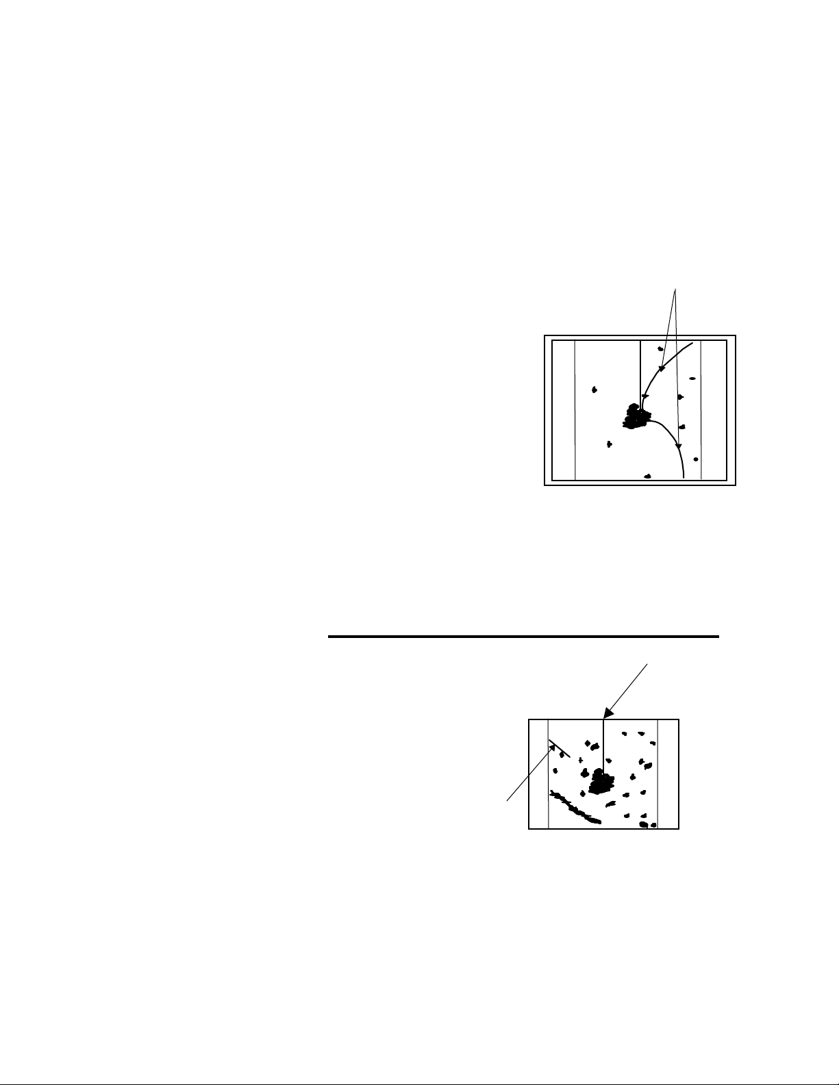
Rad a r inrte rfer e n c e
Radar interference
If a radar operating in the same frequency exists near
your ship, interference noise may appear on the screen
that is caused by transmitted waves from that radar. This
int er fere nce appe ar s in va riou s way s. I n most case s, h owever, i t appears as spi r al o r radial patterns.
3
1
HU
The RA40C/41C/42C radar has a function to eliminate interference . Use of this function hel ps you minimize
interference.
Fig.2-8 Ra dar interfer-
ence
2.3 Terms Specific to Radar
HM(Heading Marker)
HM (Headin g Marker)
This is a line-shaped marker used to indicate the advancing direction of your ship.
North Mark
This mar ker indica te s th e nor th di re ctio n.
It is a short line approximately 1/6 of the
screen size.
0.75
0.25
HU
North Mark
Fig.2-9 Heading Marker and
North Mark
6
Page 17
Display modes
This refe rs to a ra dar's dis pla y mo des. The re are fou r displ ay mode s de pen ding on t he
dir ec ti on i n whic h th e to p of th e s creen faces with respect to th e ship.
Ship's
Heading
Scheduled
North
Scheduled
course
Ship's locus
(not displayed on screen)
North
course
0.75
0.25
TM
HM
0.75
0.25
HU
0.75
0.25
NU
0.75
0.25
CU
North
mark
North
HU
EBL
NU CU
TM
Fig.2-10 Display modes
Head Up (HU)
In this mode, the ship's heading always indicates the upward direction of the
scre en. This mode le t s y ou kn ow t he relat ive po sition s o f y o u r shi p a nd ot her sh ips or
land.
North Up (NU)
In this mode, the north direction always indicates the upward direction of the
scre en, al lowi ng you to co mpar e y our ship posi tion wit h a mar ine char t a s you nav igate.
Course Up (CU)
The sh ip's h e ading i n a cou r se-up mo de alw ays i ndi ca te s t he u pwa r d di r ecti on o f
the screen as the bearing toward the destination. In this mode, the ship can be maneu ve red to sail t he short est dist ance to t he dest ina tio n by st ee rin g it in such a wa y
tha t its h eading marker alwa ys dire cts to t he u pward di recti on of the scree n. If t he
ship dr i ft s du e to t i da l cu r r e n t , ca r e must be t ake n beca u se t he fi xed t arge ts mov e to
other positions.
True Motion (TM)
In this mode, the ship is displayed as if it is moving on a marine chart while the
fixed targets such as islands and seashores are fixed in position. When the ship
reac hes a certai n p os ition on th e screen (appro x. 2/3 of sc r een s i z e) , the ship is placed
back to the op pos i t e side o n th e screen. ( Th e t op of t he s creen f aces north. )
Not e: Nav iga tion eq u i pme nt such a s a g y r o compass or mag n e t compass mu st be connected to your radar system before it can be operated in NU, CU, and TM modes.
(Refer to Section 3.9 for details on how to connect your radar to navigation equipment.)
7
Page 18
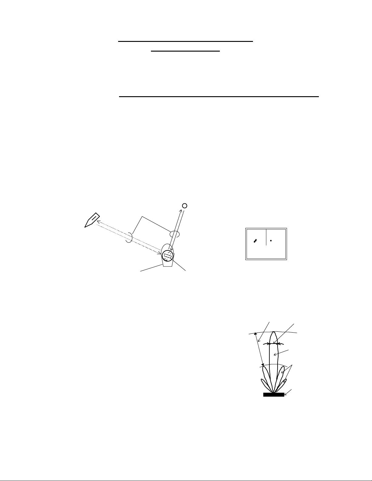
VRM (V ariable Range Marker)
This is a ci r cu l a r - shape d mar ker w ho se si z e ca n be ch a ng ed a s de si r e d. Y ou ca n use
this marker when you want to examine the distance of an echo from your ship.
When measuring the distance of an echo from your ship, be sure to measure at a
point c lose t o th e cen ter of the ec ho image on the s creen.
0.75
0.25
HU
Echo
VRM
VRM
Fig.2-11 VRM
EBL (Electronic Bearing Line)
Th i s is a marker shaped like a s tr ai ght lin e segm en t that can be chan ged to any direc-
tion centering around the ship position. Use this marker to examine the advancing direction of your ship and its relative angle with an echo. When measuring the angle of an echo,
pos i t i on the mar ker a t t he c ent er of t he echo .
0.75
0.25
HU
Equal intervals
EBL
Echo
EBL
Fig.2-12 EBL
8
Page 19
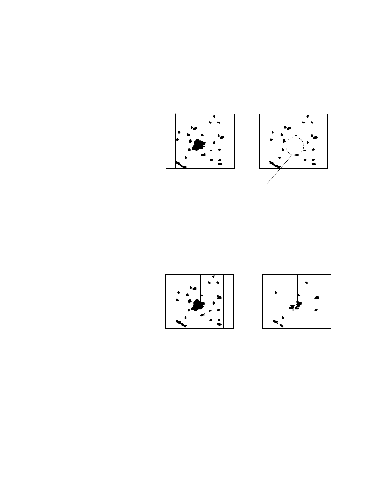
STC (Sensit iv ity Time Con trol)
Since echo signals received by the radar are strong when they are coming from a short
dista nce, it is dif ficult to compa re sig nal st rengt h bet wee n each re flect ed sign al. To o ver come this difficulty, signal strength is adjusted in such a way that the received signal levels
coming from a short distance are lowered and those from a long distance are raised. This
function should prove useful when there are large reflected waves from sea surfaces during
rough weather.
0.75
0.25
HU
STC OFF STC ON
0.75
0.25
HU
Echo is suppressed
around center
Fig.2-13 STC
FTC (Fast Time Constant)
When it rains or snows, fine noise may appear over the entire screen, making it difficult to identify echoes. In such a case, echo images on the screen can be made easily distinguishable by adjusting FTC.
FTC OF F FTC ON
0.75
0.25
HU
0.75
0.25
HU
Small noises
are reduced.
Fig.2-14 FTC
9
Page 20
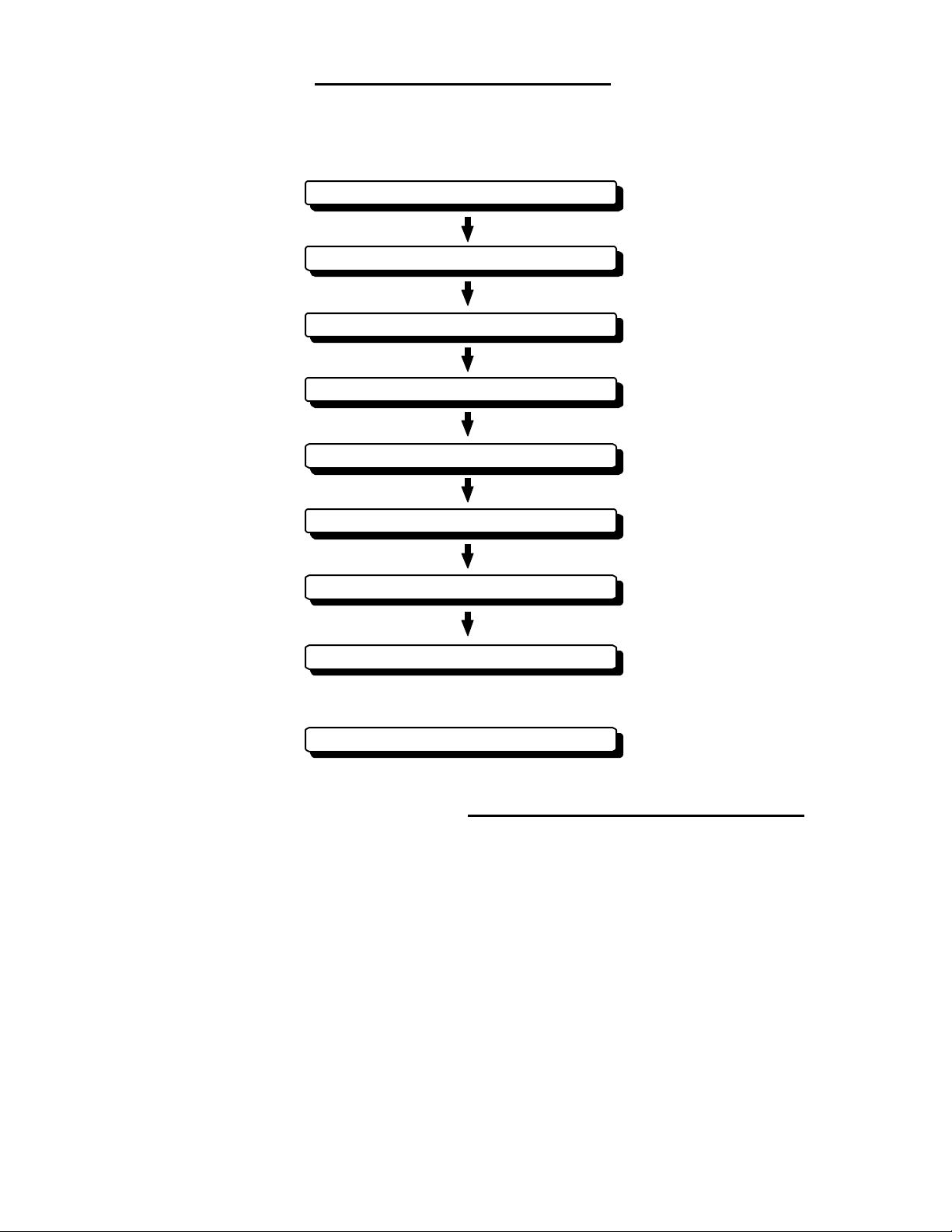
CHAPTER 3. INSTALLATION
This chapter describes procedures for installing the RA40C/41C/42C radar in your
ship and precautions to be observe d during installa t ion. Follow t he pro cedur e be low to install the radar.
Checking contents of your package
Checking power supply voltage
Determining place of installati on
Installing scanner unit
Installing dis play unit
Connecting cables
Adjustment
Connecting external equipment
When discarding Your radar
3.1 Ch ecking Cont ents o f You r P ackage
First, unpack your package and see if all of the following items are included.
RA40C RA41C RA42C
Item Q'TY Q'TY Q'TY
Display unit 1 (RF719A) 1 (RF719A) 1
(RF719A)
Scanner unit 1 (R B714A) 1 (RB715A) 1
(RB716A)
Display cover 1 1 1
Fuse 2 2 4
Interconnecting cable 1 (10 m) 1 (10 m) 1 (10 m)
Power supply cable 1 (2 m) 1 (2 m) 1 (2 m)
M10 hexagonal bolt 4 sets 4 sets 0
M12 hexagonal bolt 0 0 4 sets
Carbon brush 0 0 2
10
Page 21
The package contains a 10m i nterconnecting cable as an accessory. Longer cable is
also available as an opti on as listed i n T ab. 3-1.
Tab. 3-1 O ptional In terc onnectin g Ca b le
RA40C RA41C RA42C
Cab le leng t h Produc t No. Produc t No. Product No.
15m 242J160680B 24Y159099B 24Y159169B
20m 242J160680C 24Y159099C 24Y159169C
25m 24Y159099D 24Y159169D
30m 242J160680D
In addition to the above components included with your package, the following items
are al so r equi red. P leas e prepar e them s epar atel y .
Item QTY Remarks
Tapping screw or M5 bolt and nut 6 sets To install display unit
Grounding wire 1 E arth line for display unit
Grounding wire and crimp terminal 1 set E arth line for scanner unit
3.2 Ch ecking Pow er S up ply Voltag e
3.2.1 Power S upply Requiremen ts
For the RA 40C/41C/4 2C ra dar to be ope rate d normally , the p owe r suppl y (ba tte ry)
detailed in Tab.3-2 is required. Note also that if the batte ry is discharged, its volta ge may
fluctuate greatly, causing the radar to malfunction. When start up the radar system or start
transmitting, an additional rush current is required on the power line. Carefully check the
power supply system including wiring by using a circuit tester.
Tab. 3-2 Power Supply Req uirements
Supply voltage
Maximum curr ent Allowable r an ge of v ol t age
used
DC12V 5A 10.2-41.6V
DC24V 2.5A 10.2-41.6V
*A.C. power cannot be used
3.2.2 F use Replac ement
For the RA40C/41C/42C radar to be o perated safely, proper rating fuses must be
use d. Tab. 3. 3 and Tab. 3. 4 are fu se r at ing t abl es for RA40C /41C a nd RA 42C . C heck the m
and repla ce to t he f use i n th e pac kag e.
Tab. 3-3 Supply Voltage to Fuse Tabl e f or RA40C/41C
Supply voltage
Main Fus e Motor Fus e
used
DC12V 8A/250V or 125V *
(6.3• x 32mm)
DC24V 8A/250V or 125V
(6.3• x 32mm)
T3.15A/250V or 125V *
(5• x 20mm)
T3.15A/250V or 125V
(5• x 20mm)
Tab. 3-4 Supply Voltage to Fuse Tabl e f or RA42C
11
Page 22
Supply voltage
Main Fus e Motor Fus e
used
DC12V 10A/ 250V or 125V
(6.3• x 32mm)
DC24V 8A/250V or 125V *
(6.3• x 32mm)
Note: Marked * fus e s are in the set as sta ndard.
•••
3.3 Determini ng P lace of In st allat ion
3.3.1 Sc anner unit
A radar's target detection capacity varies greatly depending on the fitted position of the
scanner. An ideal fitting position is a location high above the ship's keel line where there is
no obstacle all around the scanner. In an actu al ship, such an ideal locat ion is limited by
various f actors. Therefo r e, c on sider t he f oll owi ng sug g esti ons when y ou determine the place
to install the scanner:
(a) Install scanner at a position as high as possible.
The higher the installation position, the longer the radio ranging distance.
Install the scanner at a position as high as possible after considering the ship's
hull structure and radar maintainability.
(b) Install scanner away from smoke-stack and mast
I f the scan ner is inst al led a t t he same he ig ht as th e smoke -st ack or ma st,
radar waves may be blocked, creating shadow zones or generating false echoes.
Therefore, do not install the scanner at such a position.
(c) Install scanner forward away from obstacle.
To avoi d cre a t ing sha dow z ones or g e nerati ng fa lse echoes, inst a ll t he scanner at a position neare r t o the ship's bow away from obsta cles. When installing
the scanne r on a ma st, p osit ion it i n fro nt of t he mast. (I f obst acl es cann ot be
avoided for the ship's structural reasons, refer to "Shifting away from obstacles"
described Page 13.)
(d) Do not install the scanner near hot or heat-generating items.
Do not install the scanner at a position where it may be subjected to smoke
or hot air from smokestacks or heat from lamps.
(e) Install the scanner away from antennas of oth er equipment.
Install the scanner as much away from the antennas of a direction finder,
radio transceiver, etc. as possible.
5A/250V or 125V
(5•x 20mm)
T3.15A/250V or 125V *
(5• x 20mm)
!
CAUTION
To eliminate the interference, install the scanner
away from th e anten na of radio transceivers.
(f) Make the cable length as short as possible.
Keep the distance from the scanner to the display unit within the standard
cable length of 10 m. If you use longer cable for unavoidable reasons, limit the
cable length to a maximum of 30 m for RA40C and 100 m for RA41C/42C.
3.3.2 D ispla y unit
The display unit can be installed on desktop, wall surface, or ceiling. Dete rmine the
place to install the display unit that is convenient for nav igation and radar opera tion after
considering the following suggestions:
12
Page 23
(a) A place where you can s ee the ship' s bow when you rai se you r face f rom t he
radar screen.
(b) A plac e wh ere there is n o dir ect sun-li ght to av o id display t emperatu re up.
(c) A place where there is good ventilation and minimum vibration.
(d) A place where the display unit is a part m ore tha n the min im um safe dis-
tance from a magnet compass as listed in Tab.3-5 below.
Tab.3-5 Minimum Safe Distance from Magnetic Compass
Master compass Steering compass
Scanner unit
Display unit
2.0m 1.4m
2.0m 1.4m
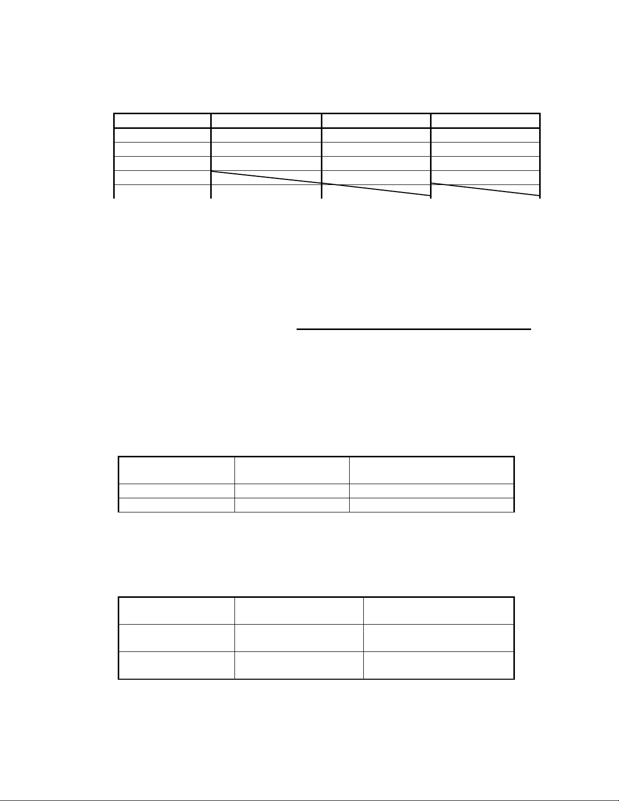
3.3.3 Sh ifting away from obsta cles
!
! Shifting from keel line
!!
By shifting the scanner position from the keel line to the starboard side of
the ship, it is possible to move shadow zone s to the p ort side which makes it
possible to keep clear vision in the bow direction. The distance to be shifted can
be obtained by calculation depending on the distance from the scanner to obstacl es using the f oll owi ng equa tion:
Ls=0.4R+D/2 [m] (when R<15m)
Ls=0.025R+D/2 [m] (when R>=15m)
where Ls = distance to be shifted from keel line
D = di am et er of ob stacle on keel li ne
R = distance from scanner to obstacle
Scanner Unit
Ls
Obstacle
D
Keel line
R
Fig.3-1 Shif ting from keel line
Obtaining sufficient dip angle
""""
Raise the scanner position so that there is a sufficient dip angle θ available
between the line of sight from the scanner to the obstacle and the horizontal
line. By raising the dip angle above 5°, it is possible to prevent mid- and longdistance shadow zones. The radar cannot detect objects below the line of sight.
13
Page 24

θ
Horizontal line
Line of sight
Fig.3-2 Obtaining sufficient dip angle
14
Page 25
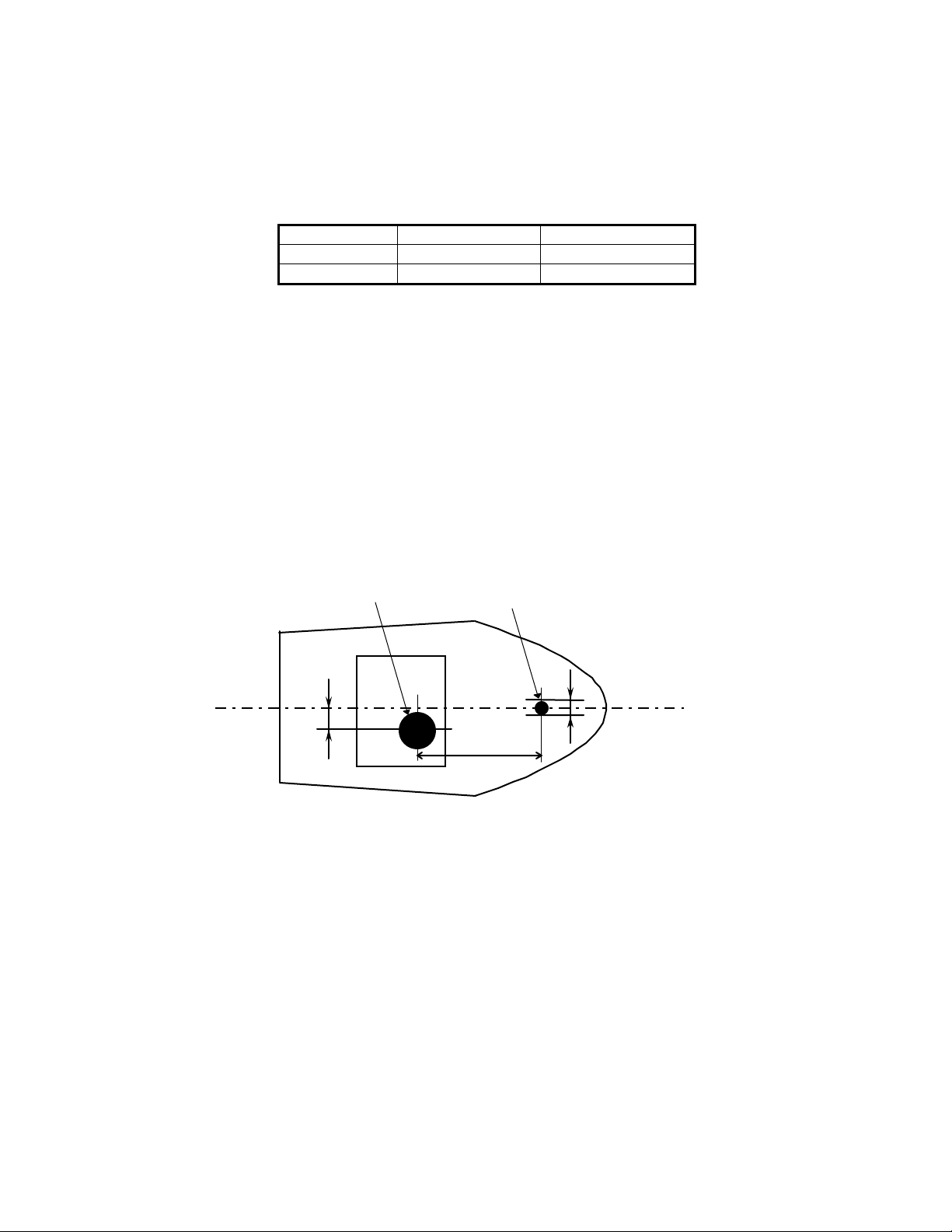
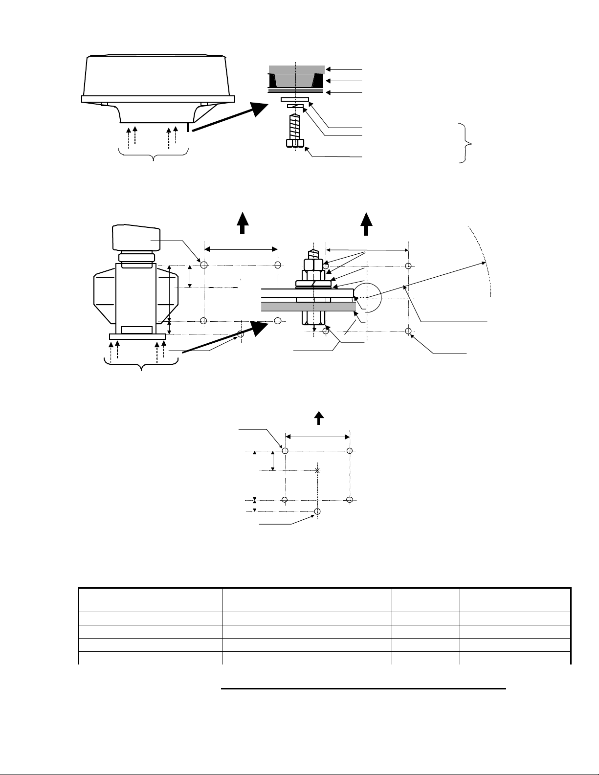
3.4 I nstalling S canner Unit
When you have decided the place of installa tion, install the scanner unit. I f a mou nt
base like the one shown below is available, it may be easie r t o install the scanner. I f such a
mount base is not ava ilable in your ship, you may install the scanner directly to the roof,
etc. In s uch a cas e, p ay atten ti on to the water d r ai n tube loc ated at th e bottom of the scanner unit during installation.
Note : When the radar mast or mounting bracket has a curvature of more than 2mm, repair
it o r u se s pacers.
Do not use an edge that might trap water.
Fig.3-3 Mount base
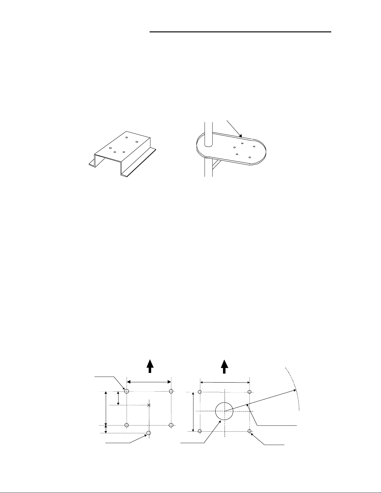
Referring to Fig.3-4, open holes in diameter of 12 mm (0.47 in.) at five locations in the
mount base and use these holes to fix the scanner unit to the mount base with hexagonal
bolts. (Use the template included with t his manual.) The bolts included wit h your radar
equ ipment will suffice for mount base thickness of 9 to 14 mm (0.35 to 0.5 5 in.). I f the
mount base is thicker or thinner than this, prepare bolts listed in Tab.3-6.
Use sealing of silicon when you prevent the bolts from becoming loose. Radome may be
bro ken i f yo u use lo cking putty.
(0.47 in.)
170
(6.69 in.)
35
(1.38in.)
12φ × 4
(2.56 in.)
For air tube
15φ
65
Forward
199
(7.83 in.)
RA42C
Open scanner
(0.59 in.)
RA41C
Radom e scann er
Forward
214
(8.43 in.)
Center
185
(7.28 in.)
Cable inlet
100φ
(3.97 in.)
Fig.3-4 Hole positions for mounting scanner
15
Rotation Radius
R550 (3 ft antenna)
R700 (4 ft antenna)
14φ × 4
(0.55 in.)
Unit:mm
Page 26
Chassis
Radome(bottom)
Mount base
Washer
Spring washer
Included
M10 Hexagonal bolt
Fix four screws
RA40C/4 1C Radome sc anne r
12φ × 4
(0.47 in.)
170
(6.69 in.)
35
(1.38in.)
Fix four screws
65
(2.56 in.)
For air tube
(0.59 in.)
15φ
Forward
214
(8.43 in.)
Forward
199
Double nuts
(7.83 in.)
Spring washer
Washer
Center
RA41
Radome scanner
Fig.3-4 Hole positions for mounting scanner
RA 42 C O p en scann er
12φ × 5
Fig.3-5 Fixing Scanner Unit
(0.47 in.)
60
(2.36 in.)
140
(5.51 in.)
185
(7.28 in.)
Cable inlet
100φ
Forward
(5.51 in.)
Center
(3.97 in.)
140
Scanner base
Mount base
M12 Hexagonal bolt
RA42
Open scanner
Rotation Radius
R550 (3 ft antenna)
R700 (4 ft antenna)
14φ × 4
(0.55 in.)
Unit:mm
Tab. 3-6 Bolts for Mountin g Scann er Unit
Thi ckness of
mount base
1-4mm(0.04-0.16 in.)
4-9mm(0.16-0.35 in.)
9-14mm(0.35-0.55 in.)
14-19mm(0.55-0.75 in.)
3.5 I nstalling Antenna Unit
30
(1.18in.)
For air tube
RA40C • Radome scanner
••••••
Bolts necessary to
Material Remarks
fix radome scanner
M10/M12 × 15 (1.5mm pitch)
M10/M12
×
20 (1.5mm pitch)
M10/M12 × 25 (1.5mm pitch)
M10/M12
×
30 (1.5mm pitch)
Stainless
Stainless
Stainless Included with radar
Stainless
16
Page 27
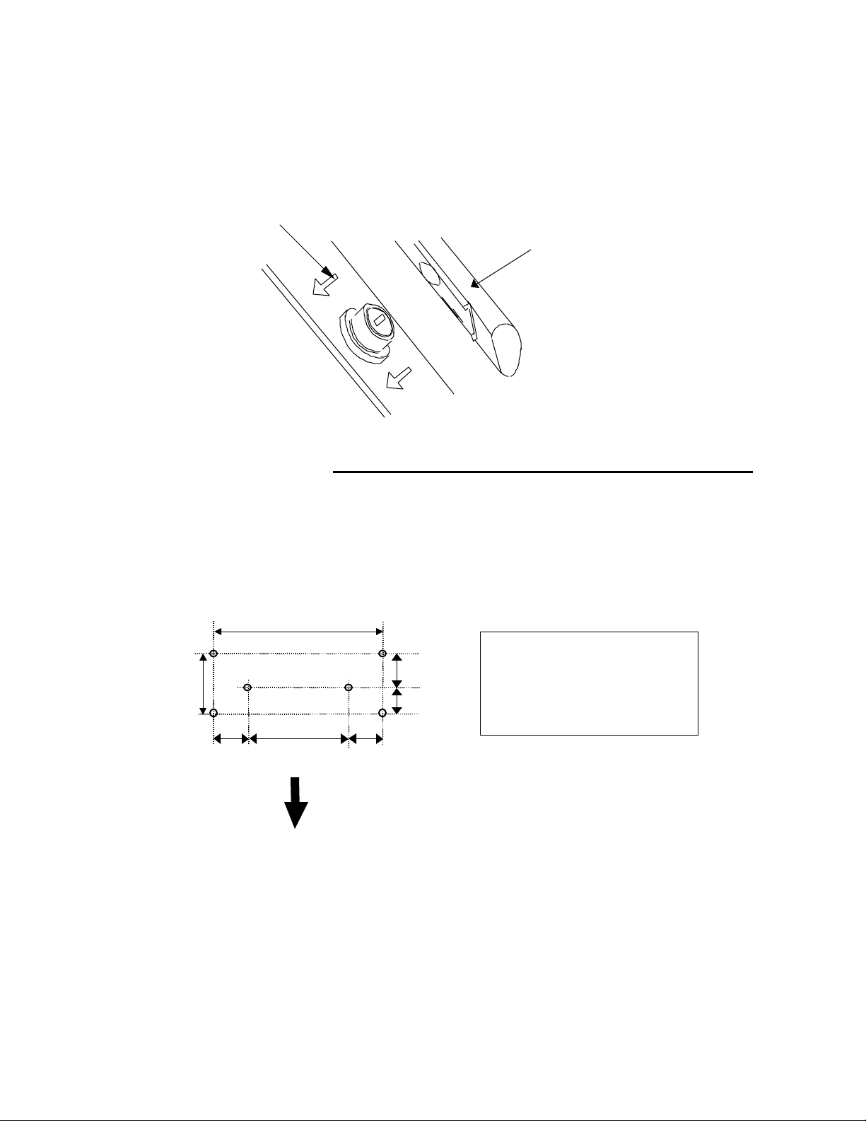
Remove th e protec t ive cap c overi ng the ro tar y co u pler on the to p o f t he s can ner. M a tch
the antenna rad iatio n d i rectio n to d i rectio n of the arrow mark i n gs o n the rotation base and
fix the antenna in position using the four M8 accessory bolts.
Arrow
3.6 I nstalling Display Un it
After y ou have finished installing the scanner unit, in sta ll the display unit in t he sa me
way. Choose the proper bolt length according to the thickness of the surface on which you
are g oing to install the display unit. Hole dia meter is different u sing bolts fro m using ta pping screw. When using tapping screw, open holes in adequate holes. When using bolts and
nuts, open holes in diameter of 6 mm (0.24 in.). When you have opened holes, install the
pedestal part first and then the display unit.
360
(14.17 in.)
84
(3.31 in.)
60
(2.36 in.)
240
(9.45 in.)
Fitting hole
60
(2.36 in.)
47
37
(1.85 in.)
(1.46 in.)
Hole diameter
6mm : Bolts and Nuts
Adequate : Tapping screws
Recommended screw
M5 or equivalent
Unit : mm
Antenna radiation surface
Forward
Fig.3-6 Hole positions for display unit
Note : When you install the display by flush mount, refer to appendix "OUTLINE DRAWING".
Slide off four triangle corner cover, and fix the display unit to the panel with screws. After
fi xing the d isp l a y unit ,
put on corner covers to the corner of the display unit. See APPENDIX.
17
Page 28

!
WARNING
Avoid a display from operating under direct sunli gh t. It beco mes hi gh temp erature at in sid e of displ ay and di splay may b e broken.
18
Page 29
3.7 Co nnect ing Cables
Lay cables firmly in place by following the instructions below.
Note1: Do not bind the cable for the radar collectively with cables of other
equipment (especially power supply cable).
Note2: Leave clearance near the inlet of the display so you can remove the dis-
play unit easily. This facilitate s installation and maintenance of the display unit. (Refer to Appendix.)
Note3: Because the cable has a connector fitted on the display and scanner side,
if it is necessary to pass cable through a narrow path, fix the scanner-side
connector vertically using vinyl tape before passing cable through the
path.
Note4: Lay cable along the ship's hull or wall surface and atta ch it in place at
intervals of about 40 cm .
3.7.0 Interconn ec ting cable (RA40C Radome scanner) (See Fig.3-8-1)
!
En sure that th e rada r i s off . Conn ect the cab l e to the receptacl e labeled "SCANNER"
on the rear panel of the display unit.
"
Next , remove the upp er par t of t he rado me from the sc ann er unit . Avoid bum ping it
agai ns t t he an ten na by l i fti ng vert i cal ly. (Th er e ar e t hree f i xing sc r ews.)
#
Remove th e ta pe f ixing t he an ten na.
$
Remove th e sh i eld co ver l oc a ted o n th e aster n s i de. (There ar e thre e fi xing screws. )
%
Remov e the cabl e cla mping pla te a n d r u bber r i ng , pa ss ca bl e thr ou g h t he in t r oduction opening, put the rubber ring from both ends of it, and clamp the cable to the
scanner u ni t wit h scr ew s via the fi xi ng pl a te . Plu g t he co nnect or fit te d t o t he ca bl e
into the X1 con n ector on the PC B.
&
Replace the aluminum cover. At this time, attach a cable shield onto a ditch with
the aluminum cover. However, be careful that the cable will not be caught up betwe en th e main u nit a nd co ver .
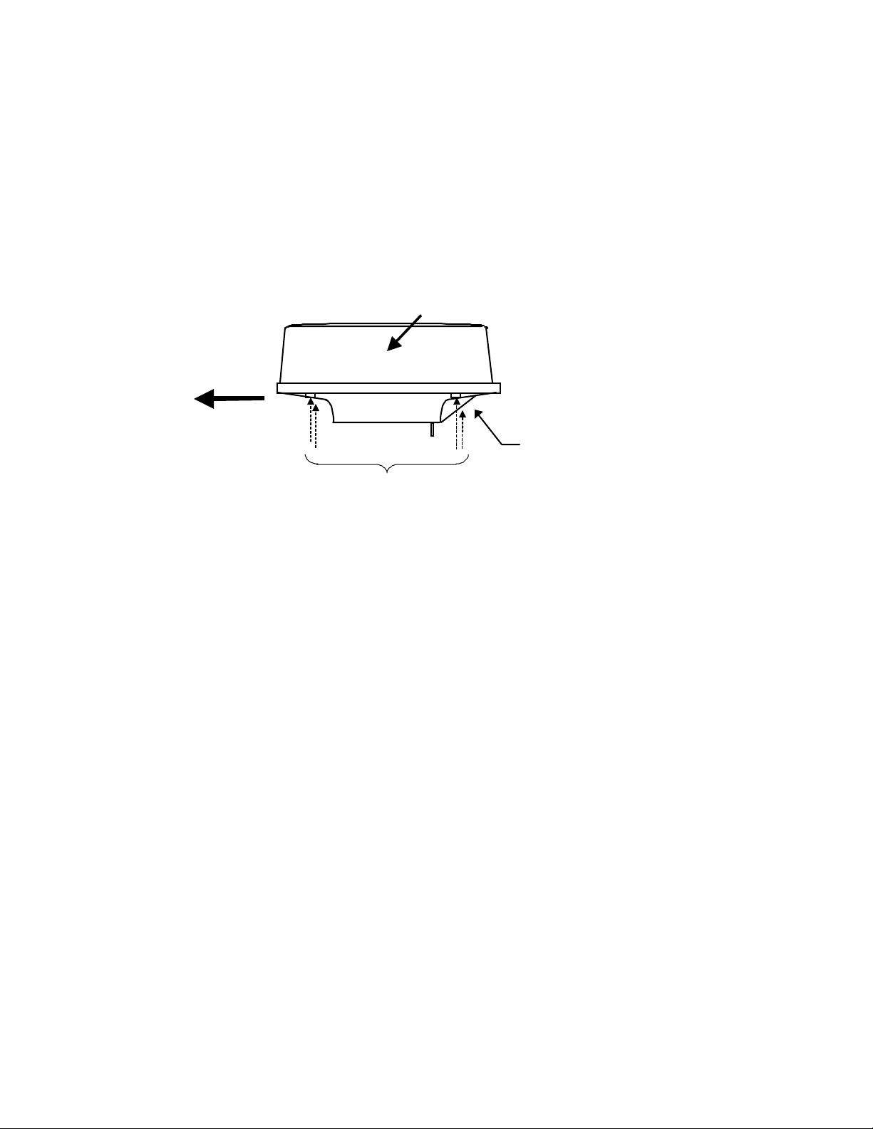
•• '
Rep l ace the up per par t o f the radome. B e c ar ef ul not to bump it agai nst the antenna
in
the same way as when removing it. Make sure that the cover is fitted in the correct
direc tion as shown in Fig.3-7-1. The upper and lower parts of the radome each have
three
markings indicating screw positions. Align the upper and lower positions as you
mount
the radome.
Logo seal on
side wall
Ship's
heading
Fixing screws
Fig.3-7-1 Fitting Cover (RA40C)
3.7.1 Interconn ec ting cable (RA41C Radome scanner) (See Fig.3-8-2)
!
En sure that th e rada r i s off . Conn ect the cab l e to the receptacl e labeled "SCANNER"
on the rear panel of the display unit.
"
Next , remove the upp er par t of t he rado me from the sc ann er unit . Avoid bum ping it
against the antenna by lifting vertically. (There are four fixing screws.)
#
Remove th e ta pe f ixing t he an ten na.
19
Page 30
$
Remove the shield cover located on the astern side. (There are four fixing screws.)
%
Remov e the cabl e cla mping pla te a n d r u bber r i ng , pa ss ca bl e thr ou g h t he in t r oduction opening, put the rubber ring from both ends of it, and clamp the cable to the
scanne r uni t w ith scre ws v ia t he fixing pla te . Conne ct 7-pin co nnect or t o X 11 an d
9-pin connector to X12 of PCB.
&
Replace the aluminum cover. At this time, attach a cable shield onto a ditch with
the aluminum cover. However, be careful that the cable will not be caught up betwe en th e main u nit a nd co ver .
'
Replace the upper part of the radome. Be careful not to bump it against the antenna in the same way as when removing it. Make sure that the cover is fitted in the
corr ect dire ction as show n in Fig. 3-7-2. The u pper an d lowe r par ts of the radome
ea ch hav e four marki ngs indi cat ing screw po siti ons. A lign the uppe r a nd low er positi ons as you mount th e radome.
Ship's
heading
Logo seal on
side wall
Cable inlet
Fix four screws
Fig.3-7-2 Fittin g cover (RA41C)
20
Page 31

A
ntenna
Radome (bottom)
Stern side
Fixing pl ate
Rubber ring
Inter c onnecti ng c able
PCB
Radome (bottom)
Cable shield
Shield cover
Fix connector on
PCB(X1)
Inner shield
X1 (Connec t here)
Fig.3-8-1 Fitting interconnecting cable (RA40C)
21
Page 32

Antenna
Radome (bottom)
Stern side
Fixing plate
Rubber ring
Interconnect ing cable
Shield cover
Cable shield
Fix connector on
PCB(X11, X12)
PCB
X11 (Conn ec t here)
Radome (bottom)
Fig.3-8-2 Fitting interconnecting cable (RA41C)
22
Inner shield
X12 (Conne c t here)
Page 33

3.7.2 Interconnecting cable (RA42C Open scanner) (See Fig.3-9)
!
Ensure that the radar is off. Connect the cable to the receptacle labeled "SCANNER"
on the rear panel of the display unit.
"
Use a T-w r enc h to r emove th e back co ver s o f scan ner unit.
#
Remove the two bolts securing the transceiver; pull out the transceiver after removing
two connectors.(to Motor(X1), to Heading switch (X2))
$
Remove th e fo ur bo lts sec u r ing the f ixing p late at t he c abl e ent r a nc e.
%
Remove the metal fixing plate, rubber seal and washer that secure the cable. Pass the
cabl e through as sh own in t he d i a g r am below; repl ace the abo ve items and tighten the
bolts.
&
Return the transceiver to its original position and secure it with the removed bolts.
'
Connect 7- pin connect or t o X1 1 and 9-pi n conn e ctor t o X12 o f PC B . A nd conn e ct two
connector that removed at #.
(
Refit the scanner covers.
Tak e care no t to pi nch th e c able wh en refitting the cover.
23
Page 34

Remove connector
Fixing bolt
Fixing plate
TR unit fixing bolts
Clumper
Inter-connection cable
Fixing bolt
Cable shield terminal
Washer
Fixing plate
Scanner unit
Inter-connection cable
Fig.3- 9 Fitting interconne cting cable
5-10 mm
Rubber
Cable inlet
24
Page 35

3.7.3 G rounding wire
→
→
p
WARNING
!
Connect grounding wire before connecting power
supply cable. Leakage current i s t oo high .
Connect grounding wire from the grounding terminal o n the re ar panel of the display
unit to the ship's hull as shown below.
Grounding wire
SCANNER
OPTI ON
POWER
Grounding terminal
Fig.3-10 Grounding display un it to earth
Connect grounding wire from one of the bolts you have a ttached when installing the
scanner unit to the ship's hull as shown in Fig. 3-11. (The cri mp te rminal and grounding
wire a re not i nc lud ed wi th th e r a dar equip ment. )
Chassis
Scanner cover
Radome(bottom
Mou nt base
To ship's hull
Crimp term in a l
Groundi ng wire
Radome scanner
Grounding wire
To shi
→→→→
Open scanner
’s hull
Fig.3-11 Grounding scanner unit to earth
25
Page 36

3.7.4 Power supply cable
Power i s fed t hr ough a k ni fe sw itch ( or cir cu i t br ea ker) a n d pr ot ect ive fuse s, a s shown
in below.
WARNING: Do not apply over 41.6V to Radar
or Rad ar m ay b e broken.
Generator Switchboard Charger
Fit the power supply cable (included with your radar) to the receptacle labeled "POWER"
on the rear panel of the display unit. And conne ct to powe r supply as f ollowings. (When you
do not connect external equipment, put tape on red and green wire.)
Pl a ce th e F u se an d conn ecti on pa r t w here there is no water splash a nd d r y ar ea .
Wh en ex tend t he p ower supp l y cable, use a s u i t abl e cable as below.
Ship's Power Voltage Cable conductor Cable max. length
cross section
12Vdc 3.5 mm
24Vdc 2.0 mm
Storage
Battery
12/24V
6.0 mm
3.5 mm
2
2
2
2
Main switch panel
(Knife Switch with
Radar Dis p lay
Unit
DC volt a g e
refer ence points
3 m
5 m
6 m
10 m
To display unit
3.8 Ad justment
Power supply cable
Fig.3-12 Power supply cable
!
Red
Green
Gray
Black
White
CAUTION
NMEA+
NMEA-
Ground
DC-
DC+
To external
equipment
To power supply
Be sure to operate the following adjustment. If this
is n ot adj usted prop erly, the rad ar pi ctu re do es not
di splay t rue imag e.
When you have finished installing the scanner and display units and connecting cables,
turn on the power to the display and scanner units and check to see if they operate normally without problem. The n make adjustments as deta iled below and check to see if the
units operate no rmall y agai n.
26
Page 37

!
TUNING Refer to Adjusting tuning circuit in 5.5.4.5.4
"
HEADING DIRE CT ION Refer to Adjusting angle in 5.5.4.5.4
#
DISTANCE Refer to Adjusting distance in 5.5.4.5.4
3.9 Co nnecting Ext ernal E quip ment to Displ ay Unit
The display unit has two channels of NM EA input. One is sta ndard in powe r cable. The
other is necessary to connect optional parts (Junction box with OPTION cable).
OPTION con nect or i s loca te d a t di spl a y’s re ar pane l for conn ect ing e xt er nal equ ipment
such as a GPS, LORA N , or gyr o com pa ss. You must ha ve an Junct i on box wit h OPTION cabl e. ( Ref er t o CH APTER 8 ( 4) External i nterface. )
Note: SIN/ C OS and MOB signal s cann ot b e us ed on Junct ion Box.
Junction box with OPTION cable (Order No. RZ704A)
SCANNER
OPTION
POWER
note
Other radar,
slave monitor,
External buzzer,
Gyro I/F
External NMEA equipment
OPTION cableJunction box*
Other radar,
slave monitor,
External buzzer,
Gyro I/F,
SIN/COS.
MOB(NMEA out)
Green :NMEARed :NMEA+
External NMEA equipment
POW ER cable
To power sup ply
Fig.3-13 Connecting external equipment to display unit
3.10 Countermeasure for El ect romagneti c Int erf erence
RA40C/41C/42C radar provides shields in the unit s and t he inte r-u nit connection cable. When the radar, however, is closely installed to radio equipment such as VHF transceiver, UHF transceiver, etc., or the radar and/or radio equipment are not sufficiently
gro u nd ed to t he hu l l or sh ip' s ear t h, the radar may hap pen to c a use EM I troub le.
Followings are general procedures for reducing EMI due t o radars. When installing ra dars, refer to them, and also check the radio equipment EMI trouble with operating the radar and radio equipment.
27
Page 38

(1) Installation Place of Radar
The display unit, scanner unit and inter-unit connection cable should be located
apart from the main unit, feeder, antenna coupler and antenna of radio equipment as
far as possible.
Especially, proper installation of the fee der, ante nna coupler and ante nna of ra dio
equipmen t is ver y i mportant to improve E MI tro ubl e.
(2) Laying Power Supply Cables
Follow ing conne cti ons A a nd B a re re commended t o r e du ce condu cti on noise ge nerated from radar. Connection C should not be used.
Connection A
(Very Good)
Connection B
(Good)
Connection C
(Bad)
(3) Grounding
All equ i pmen t sh ould be f i rmly g r oun ded a t t he earth n earest hul l with cop per plates
or braided wires.
Impr o vement Proce du re for EMI
(1 ) Co nf irm g r oun ding on the rad ar a nd r adi o equi pmen t. H oweve r , some equip ment, on
which grounding is not always necessarily, have a possibility of EMI improving w hen
taking off their gro unding. Try to take off gro unding.
(2) Confirm power supply cable connections and modify to the connection A or B above.
(3) Try to shift the display unit and inter-unit connection cable of radar to be apart from
radio equipment.
(4) Try to shift the feeder of radio equipment to be apart from each units and the inter-
unit connection cable of radar.
(5) Try to shift the antenna coupler and antenna of radio equipment to be apart from
the scanner unit and inter-unit connection cable of radar.
RADIO EQ UIP ME NT
RADIO EQ UIP ME NT
RADIO EQ UIP ME NT
RADAR
RADAR
RADAR
SHIP'S SUPPLY
SHIP'S SUPPLY
SHIP'S SUPPLY
SHIP'S SUPPLY
3.11 W hen Di scarding Your Radar
Whe n disca rding you r RA40C/ 41C/4 2C ra dar, co nsult t he dist ribut or to g et info rma-
tio n on pr eca u tion s t o be fol lo w e d. Ta b.3-7 be l ow l i st s t he pri ma r y c o m ponent mate r i a l s o f
the RA40C/41C/42C radar for your reference.
Tab. 3-7 Component Material s
Scanner unit Material Display unit Material
Radome
Chassis
Base
Antenna
AES
A5052P
ADC12
A5052P
Front panel
Rear panel
Pedestal
ABS
ADC12
ABS+PC
28
Page 39

CHAPTER 5. OPER ATION
Basic operation of radar
The RA40C/41C/42C radar has several fixed-function keys on the front panel. These
functions can be controlled by simply pressing the key. Also, special functions can be
customized to soft- keys b y user- setti ng. T he f ollow i ngs exp l a i n th e op er a tion of each key s.
5.1 Powering On and Off
(1) Powering On
Pres s the "POWER " key. Buzzer s o unds "p i " an d starts the radar sys tem.
Screen brilliance is set to the level that of the radar system h a s b een p owered o ff.
(2) Powering off
Keep pressing the "POWER" key more than 3 seconds, then the radar system will
power off.
5.2 Ad justing b rilli ance of screen and key-b acklight
(1) Press the "BRI LL" key. (Bar and figure indicating brilliance, and figure indicating keybackli g ht app ea r on t he sc r een.)
(2) Adjust each items with the control knob. Items can be selected by up-down cursor.
(3) When the adjustment is finished, press either the "BRILL" key or the "ENT" key to exit
from the adjustment screen. (Pressing some other key after adjustment will lead to the
function of the pressed key.)
BRILL -→ Control knob (Adjustment of brilliance) ----→ BRILL or ENT
→
Up/Down
(Select ion of brill iance, key-backl ight)
.75
.25
HU
ST’BY
+
BRILLIANCE 50
KEY BACKLIGHT 4
→
Other function key
Move to other functions
Page 40

5.3 Basic Operations
xxx = keys to press
5.3.1 Power ing On and Off
POWER ON
SCREEN
brilliance
key backlight
POWER
Press "POWER"key to power on.
2 minutes timer and "RADAR OFF" are displayed.
Keep pressing "POWER" key to power off.
Pres s the "BRIL" key.
BRILL
Up/Down
Control knob
Control knob
ENT Press "ENT"key to return.
Control bar i s indicated o n th e screen.
Select brilliance.
Adjust bril lianc e with kno b
Up/Down
Adjust key ba cklig ht with
knob
.
.75
.25
HU
1:58
RADAR OFF
+
Select key backlight.
BRILLIANCE 50
KEY BACK L IGHT 4
.
Rad ar turns i nto "S T' BY "mode wh en 2 minutes ti mer is fin i sh ed and
"ST'BY" is displayed.
5.3.2 Transmittin g
START
POWER
Press "POWER" key to
operate, radar picture
appears on the screen.
Another press "POWER" key,
radar turns to stand-by
mode.
Kee p pre ssing "POW ER" key mor e t han 3 se cond s, rada r
turns to power off.
CHANGE
RANGE
or
RANG UP
RANGE DOWN
Pressing " RA N GE UP" key produce s a long -dista nce ra ng e ,
"RANGE DOWN" key a short-distance range.
D‚V‚T
D‚Q‚T
‚g‚t
+
AT
30
Page 41

5.3.3 Adjusting brilliance of screen and key-backlight
xxx = keys to press
(1) Pr ess t he " B RIL L" ke y . ( B a r a n d fig ure in dicat in g br ig h t ness, a nd fig u r e in dicat in g ba cklig ht app ea r s o n th e screen. )
(2) Select brilliance or key-backlight with the up-down cursor.
(3) Adjust each item with the control knob.
(4) When the adjustment is finished, press either the "BRI LL" key or the "ENT" key to exit
from the adjustment screen. (Pressing some other key after adjustment will lead to the
function of the pressed key.)
BRIL
→ Control knob
→
Up/Down
(Adjustment of brilliance) → BRIL or ENT
(Adjustment of brightness, panel)
. 75
. 25
HU
ST’BY
→
Other function key Shift to other functions
+
BRILLIAMCE 50
KEY BACKLIGNT 4
5.3.4 Changing Distance Range (RANGE UP, RANGE DOWN)
Pressing "RANGE UP" key produces a long-distance range, and "RANGE DO WN" key a
short-distance range.
••
RADOME SCANNER (RA40C)
RANGE 0.125 •0.25 0.5 0.75 1.5 3 6 12 24
Number of
rings
Range ring
interval
RADOME SCANNER (RA41C)
RANG E 0.125 0.25 0.5 0.75 1. 5 3 6 12 24 36
Number of rings2223666666
Ran ge ring interval 0.0625 0.125 0.25 0.25 0. 25 0.5 1 2 4 6
OPEN SCANN ER (RA42 C)
RANG E 0.125 0.25 0.5 0.75 1.5 3 6 12 24 48
Number of rings2223666666
Ran ge ring interval 0.0625 0.125 0.25 0.25 0. 25 0.5 1 2 4 8
222366666
0.06250.125 0.25 0.25 0.25 0.5 1 2 4
5.3.5 Automatic adjustment ( AU T O )
AUTO adjusts the GAIN, STC and FTC automatically.
If the "AUTO" key is pressed while GAI N, STC, or FTC are u nder manua l set tings, they
will all be switched to AUTO or HBR(Harbor) mode.
Pressing "AUTO" key, AT1, AT2 and HBR changes in turn. Pressing STC key, all
31
Page 42

cont rols return t o manual s t at e .
Use when find navigation way in much echo such as port area, narrow channel,
AT1
small islands area. The control condition is similar to slightly down GAIN.
Use at ope n sea to su ppre ss th e se a cl ut te r. The cont rol c ondit ion is si mila r to
AT2
high GAIN.
HBR
Use at in a bay are a, inlet, or a harbor. The co ntrol condition becomes manual
STC by
using the value established HARBOR of ADJUST menu.
Note) Ref er to "Setting S TC c i r cuit(STC ) " i n sec ti on 5. 5.4.5.4(6).
Note) When you select HBR mode, FTC will be switched to MANU mod e.
* What happens if GAIN, STC, and FTC keys are pressed during AUTO operation?
1) If GAIN key is pressed, Only GAIN enters a manual state.
2) If FTC key is pressed, Only FTC enters manual state.
3) If STC key is pressed, STC, GAIN, and FTC enter manual state.
5.3.6 Sensitivity adjustm en t (GAIN)
(1) When the "GAIN" key is pressed, the GAIN
display on the left side of the screen will be
reversed as
G 35
and the adjustable state will be entered.
(2) When the control knob is turned, the figur e will
be shi ft ed w i t hi n a rang e o f 0 an d 99, a nd t he
. 75
.25
HU
G 50
ST’BY
+
sensitivity can be manually adjusted. When
the "AUTO" key is pressed, all (GAI N, STC and
FTC) will enter an AUTO state.
(3) After the adjustment is finished, press the
"GAIN" key to exit from the adjustment state. If
some other function key is pressed, shift to
that function will take place.
(a) To make adju st me n t s by MAN U A L (Whe n the G A IN key is pr esse d unde r AU TO o pe r at io n,
shift to a manual operation will take place.)
GAIN
→ Control knob → GAIN
µθ
>
-------------------------The adjustment state is ended.
Other function key
• ------Shift to other functions
µθ>
AUTO
µθ>
AUTO
------------------------GAIN, STC, and FT C are set at AUTO and the
adjustment state is ended.
(b) To switch from the MANUAL state
AUTO -------------------------------------------------------------------------Set GAIN, STC and FTC at AUTO
5.3.7 R emoving sea c lutter (STC)
32
Page 43

(1) When t he "STC" key is pressed, the STC display on the left side of the scree n will be
reversed as
S 35
and the adjustable state will be entered.
(2) When t he control k nob is tur ned, the figu re w ill be shifted wit hin a ra nge of 0 and 9 9,
and the STC can be manually a djusted. When the "A UTO" key is pressed, all (GAI N,
STC and FTC) will enter an AUTO state.
(3) After the adjus tmen t i s fi nished , press the "S TC" key to exit from the adjustmen t state.
If some other function key is pressed, shift to that function will take place.
(a) To make a dj u st me n t s by MA NUAL ( When t h e S TC key is pr esse d unde r A U TO ope r a tion ,
shift to a manual operation will take place.)
STC
→ Control knob → STC
→Other function key
→ AUTO
NOTE) When you se lect MANU mode, GAIN and FTC will be switche d to MANU mode, t o o .
→ AUTO
----------------------------The adjustment state is ended.
• --------Shift to other functions
--------------------------ST C, GAIN, and FTC are set at AUTO and the
adjustment state is ended.
(b) To switch from the MANUAL state
AUTO -------------------------------------------------------------------------Set STC, GAIN and FTC at AUTO
5.3.8 R emoving ra in and snow cl utter (FT C)
(1) When the "FTC " ke y i s pr e ssed, t h e F TC di spla y
on the left side of the screen will be reversed as
F 500
and the adjustable state will be entered.
(2) When the control knob is turned, the figur e will
be shi ft ed w i t hi n a rang e o f 0 an d 99, a nd t he
sensitivity can be manually adjusted. When
. 75
.25
HU
F 50
ST’BY
+
the "AUTO" key is pressed, all (GAI N, STC and
FTC) will enter an AUTO state.
(3) After the adjustment is finished, press the
"FTC" key to exit from the adjustment state. I f
some other function key is pressed, shift to
that function will take place.
(a) To make a dj u st me n t s by MA NUAL ( When t h e F TC key is pr e ssed unde r A U TO o perat io n,
shift to a manual operation will take place.)
FTC
→ Control knob → FTC
-------------------------The adjustment state is ended.
>
µθ
>
AUTO
µθ
µθ
Other function key
>
AUTO
------------------------GAIN, STC, and FT C are set at AUTO and the
-------Shift to other functions
adjustment state is ended.
(b) To switch from the MANUAL state
AUTO -------------------------------------------------------------------------Set GAIN, STC and FTC at AUTO
33
Page 44

5.3.9 Man O v er Board (MOB)
Pressing the MOB key will send the own ship's p osition data t o the external equipment
thro ugh NM EA port with "WPL" f ormat. Th ere i s no ch ange on the screen.
To ch ec k the MOB po sition data, selec t "MOB" from th e "W INDO W " men u i n the "SE TUP ".
The position of MOB and current position will be di splayed on the s cre e n. I f press the "MOB"
key while watching the MOB screen, MOB data w ill be clea re d and re tu rn t o previous screen.
If press other keys, MOB data will be remained and return to previous screen.
34
Page 45

5.4 Functions of Soft Keys
xxx
•keys to press
•
Outline of soft keys
Any funct ion ca n be opt iona lly all ocat ed t o t he ke y u pon wh ich nu mber s 1-7 a re indi ca te d. A
maximu m of 4 groups of fu nction s can be allo cate d to each soft key , and swi tching be twee n
those functi ons is cond ucted by the "NEX T" key.
5.4.1 Bearin g measurement (EBL1)
(a) Bearing measurement by EBL1
(1) Whe n "EBL1" ke y i s pr esse d, e l e ctri c bea r in g li ne (EBL1) appe a r s and the a ng l e fr om t he
direction of the ship’s head which is set at 0 °will appear in a reverse display at the lower left
of th e sc r een(N ote) .
(2 ) Us e t he c ont r ol knob t o place the direction curso r on th e ta r g et, an d read the an g l e.
(3) After the setting
i) If "EBL1" key is pressed, the setting is completed.
ii) If "other function" key is pressed, the function w ill be shi fte d to that of the pre ssed ke y
with the setting condition still in effect.
note: 1 xxx.x φ indicates EBL1.
EBL1
→ Control knob → EBL1
µθ>
EBL1
µθ>
Other function key
EBL1 is displayed and the process is finished.
EBL1 is displayed and the function is shifted.
EBL1 is turned off.(b)
(b) To turn off the EBL1
When the "EBL1" key is pressed twice, EBL1 disappears. (EBL1 OFF)
Note: Refer to "5.5.1.1 Bearing measurement (EBL1)".
5.4.2 Bearin g measurement (EBL2)
The operation is the same as EBL1. Refer to the EBL1 operation. The " EBL2" will ap pea r
in a r everse disp lay at t he lower r i g ht o f the s creen
5.4.3 D istanc e measurement (VRM1)
(a) Distance measurement by VRM1
(1) Whe n " V RM1" ke y i s pr esse d, va r iable rang e ma r ker ( V RM1) appe a r s a nd t he dist ance in
a reverse display appears at the lower left of the screen.
(2) Place the marker on the front edge of the target with the control knob and read the
distance.
(3) After the setting
i) If "VRM1" key is pressed, the setting is completed.
ii) If "ot her function" key is pressed, the function will be shi fted t o that of the pressed key
with the setting condition still in effect.
note: 1 xxx.x NM indicates VRM1.
35
Page 46

VRM1
→ Control knob → VRM1
µθ>
Other function key VRM1 is displayed and the function is shifted.
VRM1 is displayed and the process is finished.
µθ>
VRM1
VRM1 is turned off.(b)
(b) To turn off the VRM1
When the "VRM1" key is pressed twice, VRM1 disappears. (VRM1 OFF)
Note: Refer to "5.5.1.2 Determining the distance (VRM1)".
5.4.4 D istanc e measurement (VRM2)
The operation is the same as VRM1, re fer to VRM1 opera tion. The "VR M2" will a ppear in
a rev er se disp lay at the low er r igh t of the s creen
5.4.5 Measuring the angle between two points (FL EBL2)
Note: VRM2 and EBL2 do not follow the OFF-C function while floating.
Note: Refer to "5.5.1.5 Measuring the distance or angle between two points ( FL EBL2, FL
VRM2 )".
(a) Setti ng a r efe r enc e po int fo r m ea surement of t he an g l e.
(1) Press "FL EBL2" key. “SET START POINT” is displayed and a small cross mark appears.
FL EBL2 → FL EBL2 is turned ON and
(Select FL EBL2) the small cross mark appears.
(2) Use the le ft-rig ht a nd up-down cursor keys to place t he small cross mark on one o f t he
two echoes whose angle will be measured, and press the "ENT" key.
Up/Down & Left/Right
(Place t he cross cursor on an echo)
→ ------ ENT
Criterion of the reference point is set.
(b). Measuring
Perform the operations in the above mentioned and "measuring the angle(EBL2)", and
pl a ce th e EBL2 on anot her echo.
EBL2 is displayed on the screen based on the placed fixed cross cursor.
" 2 xxx.x°" which is displayed at the lower right will be the angle between the two
points.
5.4.6 Measuring the distance between two points (FL VRM2)
Note: Refer to "5.5.1.5 Measuring the distance or angle between two points ( FL EBL2, FL
VRM2 )".
(a) Setti ng a r efe r enc e po int fo r m ea surement of t he an g l e.
36
Page 47

(1) Press "FL VRM2" key. “SET START POINT” is displayed and a small cross mark appears.
FL VRM2 → FL VRM2 is turned ON and
(Select FL VRM2) the small cross mark appears.
(2) Use the le ft-rig ht a nd up-down cursor keys to place t he small cross mark on one o f t he
two echoes whose angle will be measured, and press the "ENT" key.
Up/Down & Left/Right
(Place t he cross cursor on an echo)
→ ------ ENT
Criterion of the reference point is set.
(b) Measuring
Per fo r m the o perat i on s in the ab ove men tioned a nd "m ea suring the dis ta nc e( VR M2 )", and
pl a ce th e VR M2 on anot her echo.
VR M2 i s displ ay ed o n th e screen based on t he p l a ced fixed cros s cur so r .
" 2 xx. xNM" which is displaye d at the lowe r r ight will be the distance bet wee n the two
points.
5.4.7 Changing the group of Soft Keys (NEX T )
Any fu n ct i on can be opt i onall y a l lo ca t ed t o the key u pon w hich n umbe r s 1-7 a r e i ndica te d.
A max imu m of 4 gr oups of funct ion s can be all ocat ed t o e ach so ft ke y, a nd swit ching be t wee n
those functi ons is cond ucted by the "NEX T" key.
The "NEXT" key switches between allocated function groups on the soft key which numbers
1-7 are indicated.
Εϖερψ τιµε πρεσσινγ τηε ∀ΝΕΞΤ∀ κεψ,
7 7 7NEXT NEXT NEXT
function groups changes to another groups included
7NEXT
pressing "N EXT" key. The function groups can also be changed at the "KEY ASSI GNMENT"
fun ctio n i n th e "CUS TOM" m en u of the "SET UP" with l ef t- r i ght cur sor key.
Operation_
_Soft Key Setting Example_
SET1 SET2 SET3 SET4
EBL1
VRM1
VAR RNG
TRACK
TARGE
SEL WIN OFF-C PICTURE
NEXT NEXT NEXT
1
2
3
4
5
6 6 6
7
EBL2
VRM2
FL EBL2
FL
GZ
1
2
3
4
5
7 7
RINGS
TUNE
ST
ZOOM
SLEEP
1
2
3
4
5
PPI
PPI/3D
PPI/PP
PPI/NAV
ALL
ALL
1
2
3
4
5
6
7NEXT
37
Page 48

The function can be changed at the "KEY ASSIGNMENT" function in the
"CUST O M" menu o f the "SETUP ".
38
Page 49

5.4.8 Erasing heading maker temporarily (HDG OFF)
Press the “HDG OFF” key. The heading marker is not displayed as long as you hold it down.
5.4.9 Using parallel cursors (///CSR)
Press the “///CSR” key . Parallel cursors will appear on the scree n. As you move EBL, t he
parallel cursors also move.
To cancel the "///CSR" function, press "///CSR" key once more.
Note: Refer to "5.5.1.8 Using parallel cursors (///CSR)".
5.4.10 Establishment of the indication of the RANGE RIN GS (RINGS)
Press the “RINGS” key. Range Rings will appear on the screen. To cancel the "RINGS"
fun ctio n , press "R INGS " key on ce mor e.
Note: Refer to "5.5.1.9 Establishment of the indication of the RANGE RINGS (RINGS)".
5.4.11 ON / O FF of variable range function (VAR RNG)
Usu a l l y t he ran g e ch a ng es in ste ps a s 0.5-- 0. 75- - 1 .5- -3.0- -.. ..., but u si ng t hi s funct i on wil l
enable a consecutive change such as 0.5--0.6--0.7--0.8--..... .
Pr ess t he “V A R R N G” key . T he VA R RNG fu nc tion bec omes valid and VAR will be di splayed
at the upper left of the screen (beside MODE). To cancel the "VAR RNG" function, press "VAR
RNG" key once more.
The range changes continuously with the up-down cursor while the VAR RNG function is
on, and i t chan g es i n s teps wi th the "R AN GE UP " or "R ANGE D O W N " keys.
If pressing other keys, return to the normal state from continuously range change state.
5.4.12 Changing display mo des (MODE )
(1) Select MODE fro m the pull-down display ite ms using the up-down cursor keys, and press
the "ENT" key.
(2) When the HU/HS/NU /CU /TM sign is displayed beside the MOD E ite m, sele ct display mode
with th e up-d own curs o r keys and press the "ENT" key.
(3) The setting will be completed when the "E NT" key is pressed after the selection. (NOTE1,2)
Press the "MOD E" key, the display mode will c hange on every pressing to HU, HS, NU, CU,
TM in order. The mode select at the upper of the screen is indicated. However, a setting will be
needed for the ship’s speed if TM is selected. Also, a heading or a course information is
necessary for NU, CU and TM.
νοτε: ΤΜ ισ ϖαλιδ ονλψ ον ΠΠΙ σχρεεν. Τηε µοδε ωιλλ χηανγε το ΝΥ ον τηε οτηερ σχρεεν
αυτοµατιχαλλψ.
Note: Refer to "5.5.2.1 Changing display mode (MODE)".
5.4.13 G uard Zone (GZ)
39
Page 50

A function that sets a guard zone of any distance and any angle range, creating alarm tone
when either echoes a bo ve a certain lev el exist (IN MO D E) or no echoes exist( OUT MO DE).
When GZ is operated with soft keys, guard zone settings and ON/OFF settings can be
co n duc ted , but the mode (IN or O UT) is to be set in th e menu.
Note: Refer to "5.5.2.2 Guard Zone (GZ)".
(1) When the "GZ " key is pressed, the present mode set t ing w ill be dis playe d on the left side o f
the scree n as GZ IN. A small cross cursor for set ting t he guard zone w ill be displayed a t the
screen center while "SET CENTER POINT" is displayed at the bottom, activating a guard zone
setting state.
(2 ) Us e t he up -d own / lef t-rig ht curso r keys to m ove th e cros s cur so r to the cen ter of the warning
zone to be set, and pr es s th e "ENT" key.
(3) F r om the cr oss cu r sor posi t i on se t in ( 2) a bo v e a s t h e cent er, e x pa nd t he g ua r d zone in the
direction of the distance with the up cursor key and in the direction of the angle with the
rig ht cu r sor key, thu s ma ki ng t h e fo rm of a fa n . To make t he warn in g z on e smal l e r , operat e
the down cu r sor key (i n t he dir ect io n of t he dista nce) a n d t he left cu r sor ke y ( i n t h e di r ect io n
of th e angl e).
(4) After the setting th e guard zon e, fi nis h by pres sing the "ENT" key.
Pres s the G Z key twice to c ancel th e guar d zon e functio n .
GZ
→ Up/Down
ξ (Setting the center of GZ) (Setting the scope of GZ)
µθ> GZ --------------------------------------------------------------------------------------------------------Canceling GZ
& Left/Right
→ ENT
→ Up/Down & Left/Right → ENT Setting completed
•Stop the alarm tone
Press the "ME NU" key or "ENT" k ey during the alarm tone sounds, alarm tone will stop.
νοτε:
Set the mode (IN or OUT) at the "GZ MODE" of the "PRESET2" function in the
"CUST O M" menu o f the "SETUP "
Set the alarm level (IN or OUT) at the "GZ LVL" of the "PRESET2" function in the
"CUST O M" menu o f the "SETUP "
5.4.14 Off Cen ter (OF F-C)
Displaying the location specified by the cross cursor as the ship's location
Note: Refer to "5.5.2.3 Shifting display in specific direction (OFF-C)".
(1) When the "OFF-C" key is pressed, OFF-C is displayed at the upper right and "SET OFF
CENTE R P O INT " at th e botto m o f the sc r een, and s etting is ready to be entered .
(2) Move the cross cursor with the cursor keys to move the ship to the intended location, and
press the "ENT" key. The ship's location will be displayed as the cursor's location. OFF-C is
disp l ayed at the up per rig h t , whi ch indicates th at the "OFF- C" s tate is entered.
(3) To cancel "OFF-C"•fun ctio n , p ress the "OFF- C" key.
(a) T o conduct the setting
40
Page 51

OFF-C
→ Up/Down & Left/Right
→ ENT ----------------Conduct Off Center to exit the adjustment state.
Note: VRM2 and EBL2 do not follow the OFF-C function while floating.
The function operates on PPI screen only.
(b) To can cel th e s etti n g
OFF-C ---------------------------------------------------T he "OFF-C" display at the upper right disappears and function
returns to the ordinary state from the Off Center state.
5.4.15 Sett ing of the SLEEP function(SLEEP)
This function sends a 30-second-transmissions during pre-fixed hours. After a
tr ansmissio n, a pow er -sa vin g mode is ent e red wi th t he scre en i n ST'BY st at e ( the sca nner -OF F
state) and the LCD backlight turned off. This action is repeatedly executed.
Usa g e examp l e, set a gu ar d zone a nd have th e war ning sig nal auto mat i cal ly co nf irmed every
pr efixed period.
Press the "SL EEP" key . Every pressing the key, "SL EEP" function will be set a s 5-minute s,
10-minutes, 15-minutes, or off.
When a transmission is conducted after setting a SLEEP mode, a ST'BY state is entered
and the ba ckli g ht t u r ns off a ft er a 30-second- t r a n s missio n. (Pow e r - sa vin g mode ) . Two min u t es
before the fixed time the backlight turns on and the 2-minute timer starts. Then, at the fixed
time anot her 30 - second - t r ansmissi on beg ins. This seri es o f action s ar e r epeated . If any one key
is pressed during the course of this action, the SLEEP function will be canceled.
Note: Refer to "5.5.2.4 Setting of the SLEEP function(SLEEP)".
(1) Set t i ng procedure
SLEEP
SLEEP
SLEEP
SLEEP
Setting completed
→
→
→
→
(Select 5min.) →
(Select 10min.) →
(Select 15m in.) →
(Select OFF) --------------------------------------- SLEEP function is turned OFF
ENT
ENT
ENT
→
→
→
POWER ---
µ transmission ON
POWER --→30-secon d- transmission every 10 min.
µ transmission ON
POWER --→30-secon d- transmission every 15 min.
µ transmission ON
→
30-secon d-tr ansm ission every 5 min.
5.4.16 Tuning adjustment (TUNE)
(1) When the "TUNE" key is pressed, the TUNE display on the upper-right side of the
screen will be reversed as
35
and the adjustable state will be entered.
(2) When the control knob is turned, the figur e will be shifted wit hin a range of 0 and
41
Page 52

99, and the receiver tuning can be manually adjusted.
(3) After the adjustment is finished, press the " ENT" key to e xit from the adjustment
state. If some other function key is pressed, shift to that function will take place.
TUNE
state is ended.
functions
Control knob
→
(tuning adjustment) µ-> --------------- Other function key
--------------- TUNE •or ENT The adjustment
→
• Shift to other
Note: Use the "M ENU" to return auto - tun i n g stat e.
Note: Refer to "5.5.3.4 Adjusting receiver tuning (TUNE)".
5.4.17 Ech o expansion (ST)
Ex pandin g the echo to the di rectio n of the di stance.
When the "ST" key is pressed, "ST1" is displayed on the left side of the screen and the state
of echo expansion is entered. This changes the picture to display echoes expanding in the
direction of the distance. Two types of echo expansion exist, which are alternated as follows ,
every time this key is pressed.
Note: Refer to "5.5.3.5 Echo expansion (ST)".
ST1 → ST2 → OFF
Expansion rate ST1 < ST2
•
•
Not e: T he "O F F " state i s n ot d isp l a y ed o n th e screen an d th e " ST 2" displa y disappears.
5.4.18 D ispla ying locus of target (TRACK)
Wh en th e " TR A C K" key i s p r essed, " TK 15 SEC" is d is pl ay ed o n th e lef t sid e of the screen and
tr ack mo de is e nt er ed. 15 S in dica te s th e le ng th of t he tra ck, an d dis play s a max imu m o f 1 5second-lon g sailing track.
Note: Refer to "5.5.3.6 Displaying locus of target (TRACK)".
Every time this key is pressed, the course length switches as follows.
15 sec → 30 sec → 1 min → 3 min → 6 min → CONT → OFF
Note: The "OFF" state will not displayed on the screen and the "TK xx " display will disappear.
5.4.19 Enlarging selected areas (ZOOM )
The video image centering around the cross cursor is doubled as it is displayed on the
screen.
Press the "ZOOM" key to "ZOOM" ON. A small cross cursor for setting and "SET ZOOM
POINT" are displayed at the screen center and at the bottom respectively, and the magnification
point is to be set. Use cursor keys to move the cross cursor to the point to be magnified, press
42
Page 53

the "ENT" key and the setting is completed. The area around the cross cursor is displayed in 2x
magnification, with blinking "ZOOM" displayed at the screen upper right, indicating that a
ZOOM display is being conducted.
To c ancel t he ZO O M fun ction, press th e " Z O OM " key a g ain or ch ange the range sc a l e.
Note: Refer to "5.5.3.7 Enlarging selected areas (ZOOM)".
ZOOM → Up/Down & Left/Right → ENT -------------------- ZOOM setting
(Move cross cursor)
µθ> (Select OFF) → ZOOM
------------------ZOOM canceled
Note1: VRM2 and EBL2 do not follow the ZOOM function during a floating state.
Not e2: N ormal scr een retur ns when y ou c han g e t he range s cal e.
Note3: ZOOM function is unusable in 3D/PPI screen.
Note4: ZOOM function is unusable in OFF-C.
Note5: Center of ZOOM can be set any desired position within the set range.
5.4.20 Increasin g sensitivit y (S/L )
The pulse width is automatically changed as you change the range. However, if you want
to increase sensitivity, you can choose sensitivity from two pulse lengths. The short pulse
(SHORT) gives you sharp images with high distance resolution. The long pulse (LONG) provides
high sensitivity and shows targets in large size for easy identification although distance
resolution is reduced.
Press the "S/L" key to select the Pulse length(LONG or SHORT). The pulse length changes
L(Long) and S(Short) alternately.
Note: Refer to "5.5.3.8 Increasing sensitivity (S/L)".
S/L → (Select SHORT) → Set to short pulse
µθ> or (Select LONG) → Set to long pulse
5.4.21 Switchin g the screen (SE L WIN)
Switching to the desired screen for activation on a 2-screen display(PPI+PPI).
When change the range, or adjust the GAIN, STC, or FTC, or control the VRM, EBL, select the desired
screen first.
ex.) To b e used for swi tch ing th e r a nge o n th e PPI+P PI screen.
When the "SEL WI N" key is pressed, the range of the sele cted scree n w ill be displayed in
reverse, indicating that the screen is active.
Note: Refer to "5.5.4.2 Switching screens on PPI/PPI screen ( SEL WIN )".
SEL WIN → (Select right screen) → Right
screen activated
43
Page 54

µθ> or (Select left screen) → Left
75
screen activated
If VRM1 is controlled on the screen that is oposit from current VRM1 displayed screen,
VRM1 is moved and displayed to activated screen. The EBL1, EBL2, and VRM2 is the same
manner.
5.4.22 Changing the color of screen (PICTURE)
The LCD display is affected by weather and day / night environment conditions. In some
cases, y ou may fi nd th e L C D disp l a y i s ea sier t o view when t he entire color o f screen is cha nged.
Press the "PICTURE " key, a day display will appear if night display has been selected, and a
night d isp lay if day display s elected.
Note: Refer to "5.5.4.3 Changing the color of screen (PICTURE)".
5.4.23 Change to PPI screen ( PPI )
Press the "PPI" key, the screen will change to PPI
screen.
.
.25
HU
Use t o c han g e the s creen f r om ot her mod es to PP I.
5.4.24 Change to SE MI3D / PPI screen ( SEMI3D )
Press the "SEMI3D" key, the screen will change to
SEMI3D/PPI screen.
Use to change the screen from other modes to
SEMI3D/PPI.
Note: All controls, such as EBLs, VRMs effects both screen.
The ZOOM , OFF-C, FL EBL 2, an d FL VRM2 c o uld no t
be used on this mode. The "SEMI3D" screen displays
the center as ship's heading always.
5.4.25 Change to PPI/PPI screen ( PPI/PPI )
.75
.25 HU S
+
PPI screen
{
280 320 0 00 04 0 08 0
SEMI3D/PPI screen
44
Page 55

Press the "PPI/PPI" key, the screen will change to
75
PPI/PPI screen. Use to change the screen from other
modes to PPI/PPI.
.75
.2 5 HU S
24
6
Note:
{
(1) The radar picture is refreshed with two scanning
interval for each screen. Right screen picture is
holded during refreshing left screen, left screen
holded during refreshing right sc reen.
LEFT screen /---------/********/---------/********/---------/******** time
RIGHT screen ********/---------/********/---------/********/---------/
PPI/PPI screen
→→→→
G 55/35
S 35/AT
F 35/AT
(2) The ZOOM, OFF-C, FL EBL2, and FL VRM2 could not be used on this mode.
(3) The range, GAI N, STC, FTC, GZ can be use d inde pendently for selecte d window wit h "SEL
WIN".
Sel ected windo w i s that th e r a nge disp layed in rever se c hara cter. P l ea se ref er t o "S EL WIN".
(4) The cross cursor can be controlled on selected window.
5.4.26 Change to PPI/N AV screen ( PPI/NAV )
Press the "PPI/N AV" key, the screen will change to
PPI/NAV screen.
Use to change the screen from other modes to
PPI/NAV.
Note:
The ZOOM, OFF-C, FL EBL2, and FL VRM2 can not be
.25 HU s
+
NAV DISPLAY
WAY P 123.4°
6.8NM
COUR SE 2.38NM
XTE <<<<
HDG 267.3°T
SPD 12.8
TEMP 20.8
DEPTH 58.3
LAT/LON
34° 08. 22 N
138° 02 .53E
‚j‚s
C
°
M
.75
used on this mode.
PPI/N AV scre en
.
5.4.27 Change to ALL PPI screen ( ALL PPI )
Press the "ALL PPI " key, the scree n will change to A LL
.25
HU
PPI screen.
Use t o c han g e the s creen f r om ot her mod es to AL L P PI.
+
Note:
(1) The rang e , r i ng s inte r va l , di splay mo de a r e di spl a y ed on
the upper l eft o f the screen.
(2) Return to PPI screen mode pressing a key except MENU,
refreshing radar picture
ALL PPI screen
range UP or DOWN, or POWER key.
5.4.28 Change to ALL PPI / PPI screen ( ALL PPI 2 )
ho lding p revious picture
45
Page 56

Press the "ALL PPI 2" key, the scree n will change to
ALL PPI/PPI screen.
Use to change the screen from other modes to ALL
PPI/PPI.
.75
@
.25 HU S
.25 .
125
Note:
(1) The ra nge , ri ngs i nt er val, di splay mo de a re displ ay ed
{
on t he up per lef t of ea ch screen.
(2) Ret ur n to PPI /PPI scre e n mode pre ssing a ke y e xcept
MENU, range UP or DOWN, or POWER key.
ALL PPI/PPI screen
(3) The radar picture is refreshed with two scanning
interval for each screen. Righ t screen picture is holde d during refreshing l eft screen, l eft
screen holded during refreshin g rig ht sc reen. Wh en your ship navig ates in h igh speed, use
PPI screen to get fast refreshing picture.
46
Page 57

5.5.2 Nav (Na v iga tion) Menu
Radar functions for navigation aid are in this menu.
•Common operations for the NAV menu
(Up to the p oin t wh en "N AV " menu i s selected fr o m th e mai n menu)
Pre ss the "M ENU" key an d sele ct "NA V" from th e dis pla ye d 4 ma in menu s usin g th e le ft -rig ht
cursor. (The conte nts of the sele cte d MENU will appea r on a pull-down display in accordance
with th e movement of t he left- r i g ht curso r .)
xxx = keys to press
MENU
Further explanation about the NAV menu will be conducted on the assumption that this
"co mmo n o peratio n for th e NAV men u" h as already b een com pleted.
(1) Select MODE fro m the pull-down display ite ms using the up-down cur sor key, and pre ss
eithe r th e "ENT" key.
(2) When the MOD E sign is displaye d beside the MOD E ite m, sele ct a mode w it h the up-down
cursor keys and press the "ENT" key.
(3) The display mode indicates upper-left on the screen.
→
5.5.2.1 Cha nging display mode (MODE)
.75
.25
HU L
>>>
0.23 NM
Left/Right
(Select NAV)
NAVIGATION
MARK
NAV ECHO
MODE >
GZ >
OFF-C >
SLEEP >
AT
SETUP
HU
HS
NU
CU
TM
UP/DOWN --> ••• --> UP/DOWN
•Select MODE• |--> (Select HU• --> ............ ••• •••Head up•
|--> (Select HS• --> ............ •••
|--> (Select NU• --> ............ ••• •••North up•
|--> (Select CU• --> ............ •••
--> (Select TM• --> ............ ••• ••(True motion)
Note1: Navigation equipment (gyrocompass, magnet compass, or GPS) must be connected to
your radar in NU, CU and TM modes.
Note2: In TM modes it is necessary to set as follow (1) or (2).
(1) Input of speed information from NMEA. (2) Set your ship’s speed manually.
Note3: TM works only on PPI screen, NU is used automatically for the other screens.
•••Head set•
•••Course up•
52
Page 58

5.5.2.2 Guard Zone (GZ)
A fun ctio n that sets a guard zone o f any distan ce and any ang l e range, creating alarm tone
when either echoes a bo ve a certain lev el exist (IN MO D E) or no echoes exist( OUT MO DE).
Setting guard zone
(1) Se lect GZ from th e pull-down d ispl ay ite ms us ing the up-down curs or keys, and press the
“ENT” key . ON/OFF sign is displayed bes ide t he GZ item.
Up/Down
--> ENT ------------------------------- ON/OFF sign is display ed.
(2) Select “ON” by “common operation for the GZ
menu”, and press the “ENT” key.
(3) The present mode set ting w ill be displayed on the le ft
side of t he scree n as GZ IN . A sma ll cros s cu r sor for
setting the guard zone will be displayed at the screen
center while "SET CENTER POI NT" is displayed at
GZ IN
SET CENTER POINT
the bottom, activating a guard zon e setti n g stat e.
(4) Use the up-down and left-right cursor keys to move the cross cursor to the center of
the warni ng zone to b e set, an d p ress the "ENT" k ey.
(5) From the cross cursor position set in (4) above as the center, expand the guard zone as
follows.
Expand w ith the right cursor key in
the direction of the angle. Use the
left cursor key to make the zone
GZ IN
Expand with the up cursor key in the
The mode (IN or OUT) is displayed when the state is
ON. Nothing is displayed when it is OFF.
direction of the distance. Use the down
cursor key to make the zone smaller.
(6) After the setting th e guard zon e, fi nis h by pres sing the "ENT" key.
To cancel t he g u a r d zone funct ion, se l e ct “ OF F” by
“common operation for the GZ menu”, and press
the “ENT” key.
ENT
Up/Down &Left/Right
-->
( Setting th e center of GZ) (Settin g the scope o f GZ) -----------------------------------------
-->
ENT
Up/Down &Left/Right
-->
ENT ----------------Setting completed
•
-->
53
The central position of the guard zone.
With this point as the cente r, the z one
can be expanded in the directions of
the distance and the angle with the
upper and right cursor keys
Page 59

Stop the alarm tone
When the alarm sounds, press any key to stop. But the guard zone function is still
working, the alarm may sounds again. To "OFF" the guard zone function, select "OFF"
from GZ menu.
Not e1: To swit ch the I N or OUT mode, refe r t o “G u ard Z o ne Mode ” i n se ct i on
5.5.4.5. 3 “Changing
the content of settings 2 (PRESET2)”
Note2: To set the guard zone level, refer to “Guard Zone LeveL” in section
5.5.4.5. 3 “Changing the
content of settings 2 (PRESET2)”
5.5.2.3 Shifting display in specific direc tion (OFF -C)
Displaying the location specified by the cross cursor as the vessel's location.
(1) Select OFF-C from the pull-down display items using up-down cursor key, and press the
"ENT" key.
(2) When the ON/OFF sign is displayed beside the OFF-C item, select ON with the up-down
cursor keys and press the "ENT" key.
OFF-C
(3)
is displa ye d at the uppe r r igh t a nd "SET O FF C ENT ER PO I NT" a t t he bott om of
the screen, and setting is ready to be entered. Move the cross cursor with the cursor
keys to move the ship’s to the intended location, and press the "EN T" key. The ship’s
location will be displayed at the cursor's location. The display at t he u pper rig ht w ill be
no r malized from the reverse s t ate, wh ic h ind ic a tes that the "OFF - C " state i s en tered.
(4) To cancel “OFF-C” function, either select OFF in (2)
Up/Down
-->
ENT
(Select OFF-C) |
-->
Up/Down
-->
(Select ON) ENT
-->
Left/Right & Up/Down
OFF-C
-->
(Select OFF) ENT -----------------------------
Cancel OFF-C
Note: VRM2 and EBL2 do not follow the OFF-C function while floating.
The function operates only on PPI screen.
Move t he cr oss cursor i ndicat es "OFF-C" sta te is entered
.75
.25
HU
SET OFF-C POINT
.75
.25
HU
5.5.2.4 Settin g of th e SLEE P function(SLEEP)
OFF-C
-->
ENT Set
This function sends a 30-second-transmissions during pre-fixed hours. After a
tr a nsmissi on, a pow er -sav in g mode is ent ered wit h t he scr e en i n ST'B Y st a t e (the sca nn e r - O F F
54
Page 60

state) and the LCD backlight turned off. This action is repeatedly executed.
Usage example, set a guard zone and have the warning signal automatically confirmed every
pr efixed period.
(1) Use the up-down cursor keys to select SLEEP from among the pull-down display items, and
pres s the "ENT" key.
(2) When the OFF/5min/10min/15min display has a ppear e d beside the SL EEP ite m, se le ct a
tim e to be set wi th the up- down curs or keys.
(3) Press the "ENT" key and the setting is completed. When the SLEEP function is to be
canceled, select OFF in (2).
When a transmission is conducted after setting a SLEEP mode, a ST'BY state is entered
and the backlight turns off after a 30-second-transmission. (Power-saving mode). Two
minutes before the fixed time the backlight turns on and the 2-minute timer starts. Then, at
the fixed time anoth er 30-secon d-tr ansmi ssion beg ins. Thi s se rie s of a ctio ns a re re pea ted. I f
any one key is pressed during the course of this action, the SLEEP function will be canceled.
(a) Setting procedure
Up/Down
(Select SLE EP) -->
ENT
→
ENT →POWER 30- secon d-tra nsmis sion eve ry 5 min.
30-second-transmission every 10 min.
30-second-transmission every 15 min.
Up/Down -->Select OFF)
→
(Select 10 min.)
-->
(Select 15 min.)
-->
ENT -----------SLEEP fu nct ion is tur ned OFF
→
(Select 5m in.)-------------------------------
→
→
ENT →------------------------ POWER
ENT → ----------------------- POWER
Transmission
Setting com plete d
(b) Actio n after settin g
SLEEP se tting•5min.
•
•
(Under Tx•
0 sec. 30 sec. 3 min. 5min. 5and a half min.
TX Start TX OFF Backligh t ON Tx Start TxOFF •Action•
• •
•
(Under power-saving mode
•• •
2min. timer in use
Countdown start
••
(Under Tx
•••
(Under power-saving mode
Operation
•
Time used
→
•
•
•
-- What happens if a key is pressed after a SLEEP mode setting?
I f a transmissi on is condu cte d and a key is pr esse d a fte r se tt ing a SL EEP mode, powe rsaving mode is entered 30 seconds after key is pressed.
-- Wha t happ e ns if a key is pressed during the SLEEP mode?
a) If a key is pressed during the power-saving mode, the SLEEP function is canceled and the 2-
mi nute timer star ts.
55
Page 61

b) I f a ke y i s pr esse d wh ile the 2-minu te ti mer i s in use , or dur ing tra nsmis sion , the SL EEP
function is canceled.
56
Page 62

5.5.3 Ech o Menu
SETU
xxx •••keys to press
Adjus t ment o pti ons to be cond ucted o n the ec hoes displa y ed o n th e screen
•Common operations for the ECHO menu
(Up to the point whe n " ECHO" menu is se le cte d
from the main menu)
Press the "MENU" key and select "ECHO" from the displaye d 4 main menus using the le ftright cursor. (The contents of the selected MENU will appear on a pull-down display in
acco r danc e with the movement of t he left- r i g ht curso r .)
MENU
•••---> Left/Right
(Select ECHO)
When the above-mentioned operations have been conducted, the items of the ECHO menu
are vertically disp layed.
Further explanation about the ECHO menu will be conducted on the a ssumption that t his
"co mmo n o peratio n for th e ECHO men u" has al r ead y been c o m pleted.
.7 5
.2 5
H U L
>>>
0.23 NM
ECHO
MARK
NAV
ECHO
GAIN >
STC >
FTC >
TUNE >
ST >
•
AUTO
•
MANU
AT
P
5.5.3.1 Sen sibility adjustment (GAIN)
(1) Use the up-down cursor keys to select GAIN from among the pull-down display items, and
pres s eith er th e "ENT" key o r the righ t curs or k ey.
(2) Select MANU from the MANU/AUTO display beside the GAIN item using the up-down
cursor keys, and press the "ENT" key.
(3) The present state of GAIN is displayed in reverse on the
scre en le ft as
When the control knob are operated in this state, the
•G 35•
and an adjustable state is entered.
G 56
figure alternates within a range of 0 and 99 and the GAIN
can thus be adjusted.
(4) The adjustment is completed by pressing the "ENT" key
after ad j ustment.
Whe n AUTO action i s to be e nt ere d, sele ct AU TO in (2)
and press the "ENT " key to complete the setting .
The setting value is displayed during
MANUAL op eration.
AT is displayed during AUTO operation.
(The same applies to STC, F TC and TUNE.)
56
Page 63

Up/Down --> ENT --> Up/Down
(Select GAIN) |->(Select MANU) --------------------> Control knob --> ENT
Set to MANU mode
| (GAIN adjustment)
|->(Select AUTO) ----------------------------------- --> ENT
Set to AUTO mode
5.5.3.2 Removing sea clutter (STC)
Refer to the section, “Sensibility adjustment (GAIN)”.
Up/Down --> ENT --> Up/Down
(Select STC) |->(Select MANU) --> ENT --> Control knob --> ENT Set to
MANU mode
| (STC adjustment)
|->(Select AUTO) --> ENT
Set to AUTO mode
-----------------------------------
Note: When you select MANU mode, GAIN and FTC will be switched to MANU mode, too.
Note: When you select HARBOR mode, FTC will be switched to MANU mode.
5.5.3.3 Removing rain and snow clutter (FTC)
Refer to the section, “Sensibility adjustment (GAIN)”.
Up/Down --> ENT --> Up/Down
(Select FTC) |->(Select MANU) --> ENT --> Control knob --> ENT Set to
MANU mode
| (FTC adjustment)
|->(Select AUTO) --> ENT
Set to AUTO mode
-----------------------------------
5.5.3.4 Adjusting rec eiver tunin g (TUNE)
Refer to the section, “Sensibility adjustment (GAIN)”.
Up/Down --> ENT --> Up/Down
(Select TUNE) |->(Select MANU) --> ENT --> Control knob --> ENT Set to MANU
mode
| (TUNE adjustment)
|->(Select AUTO) --> ENT
Set to AUTO mode
35
------------------------------------
57
Page 64

Indicated setting value on
manual mode,
5.5.3.5 Echo expansion (ST)
Ex pandin g the echo to the di rectio n of the di stance.
Two types of echo expansion exist, select ST1 or ST2 from the menu.
(1) Use the up-down cursor keys to select ST from among the pull-down display ite ms, and
pres s the "ENT" key.
(2) Select ST1 or ST2 from the display beside the ST item using the up-down cursor keys,
and press the "ENT" key.
Up/Down
.75
.25
HU
--> ENT -->
set ST1
set ST2
ST OFF
+
ST function is OFF
Up/Down
-->••select ST1• ............... --> ENT
|->••select ST2• ............... |-> ENT
|->••select OFF• ............... |-> ENT
( expansion rate ST1<ST2 )
.75
.25
HU
ST1
The picture to display echoes
ST1, or ST2 display,
no display on OFF state
expanded in the direction of
the distance
+
5.5.3.6 Displaying locus of target (TRAC K )
(1) Use the up-down cursor keys to sele ct TRACK from among the pull-down display items,
and press the "ENT" key.
(2) Se le ct 15 S EC, 30 SEC, 1MI N, 3 MI N, 6MI N , or CO NT fro m the displa y be side the TRA CK
item using the up-dow n c ur so r k ey s, and press th e " ENT" key.
"TRK 15S" i s displa yed on the left si de of t he scre en a nd track mode i s en tere d. 15S
indicates the length of the track, and displays a maximum of 15-second-long sailing track.
58
Page 65

Note: When PPI+PPI or ALL PPI+PPI screen mode is used, TRACK function can be used
t
75
only on CONT mode.
real echo
moving direction
disappear after select ing time
up/down
--> ENT --> up/down ........... ->••select OFF•
-> ENT
set 15sec. track
set 30sec. track
set 1 min. track
TRACK OFF
locus of target
.
.25
HU
+
TK 15SEC
he length of the track
|---->••select 15SEC• ......................... -> ENT
|---->••select 30SEC• ......................... -> ENT
|---->•select 1MIN• ........................... -> ENT
|---->•select 3MIN• ........................... -> ENT
set 3 min. track
|---->••select 6MIN• .......................... -> ENT
set 6 min. track
|---->••select CONT• .......................... -> ENT
set continue track
5.5.3.7 Enlarging selected area s (ZO OM)
The v ideo i mag e cent erin g arou nd the cross cursor is double d as it i s display ed on t he
screen.
(1) Use the up-down cursor keys to select ZOOM from among the pull-down display items, and
pres s the "ENT" key.
(2) Select the ON using up-down cursor keys from the ON/OFF display beside the ZOOM item,
and press the "ENT" key.
(3) A small cr oss cu r sor fo r set t i ng a n d " SET ZOOM POINT" are displ a y ed a t t h e scr ee n ce n t er
and at the bottom respectively, and the magnification point is to be set. Use cursor keys to
move the cross cursor to the point to be magnified, press the "ENT" key and the setting is
completed. The area around the cross cursor is displayed in 2x magnification, with blinking
"ZOOM" displayed at the screen upper right, indicating that a ZOOM display is being
conducted.
To cancel the ZOOM function, either select OFF in (1) or begin operation of range.
59
Page 66

Up/Down --> ENT --> Up/Down (Select ON) --> ENT --> Up/Down & Left/Right --> ENT
ZOOM Setting
(Select ZOOM) | (Move cross cursor)
|--> (Select OFF) --> ENT
----------------
ZOOM canceled
Note 1) VRM2 and EBL2 do not follow the ZOOM function during a floating state.
Note 2) Normal screen returns when you change the range scale.
Note 3) ZOOM function is usable only in PPI screen.
Note 4) ZOOM function is unusable in OFF-C.
Note 5 ) Cen ter of Z O O M can be set any desi red pos i ti on wi th i n the s et range.
blinking "ZOOM"
.75
.25
HU
SET ZOOM POINT
.75
.25
HU
ZOOM
5.5.3.8 I ncreasing sensitivity (S/L)
The pulse width is automatically changed as you change the range. However, if you want
to increase sensitivity, you can choose sensitivity from two pulse widths. The short pulse
(SHORT) gives you sharp images with high distance resolution. The long pulse (LONG) provides
high sensitivity and shows targets in large size for easy identification although distance
resolution is reduced.
(1) Use the up-down cursor keys to select S/L from a mong the pull-down display ite ms, and
pres s the "ENT" key.
indicated S or
(2) Select Pulse length(SHORT or LONG) using the up-
.75
down cursor keys from the SHORT/LONG display
.25
HU
S
beside the S/L item
(3) The sett ing will be completed whe n the “ENT” key is
+
pressed after the selection.
Up/Down --> ENT -->(Select SHORT) -------------------- -->
Set to short pulse
ENT
|-->(Select LONG)--> ENT -------------- Set to long pulse
60
Page 67

5.5.4.5.2 Changing th e c ontent of setting s 1(PR ESE T1)
(1) When PRESET1 is selected from CUSTOM items and the "ENT" key is pressed, the
PRESET1 screen (See chart below) appears.
(2) Select items with up-down keys and contents with left-right keys.
The selecte d items will be enclosed by square frames and the cont ents will appear in
reversed display. (a)
Repeat this operation when multiple settings are to be made.
a) Heading Flash
b) Stern Mark
c) Nor th Ma rk
d) ST'BY screen
e) Buzzer Volume
f) VRM Uni t
g) Water temperature
h) Depth Unit
i) EBL Mode
j) WayPoint Mode
k) Heading Input
l) Heading Type
m) Cursor position
n) TX Pulse
(b)
PRESET1
HM FLASH ON _OFF_
STERN M ON _OFF_
NORTH M ON _OFF_
ST’BY _NAVI_ NO R
BUZ VOL OFF LOW _HIGH_
RM UNIT _NM_ KM SM
TEMP
DEPTH _M_ FT FM
EBL BRG _REL_ TRUE MAG
WP BRG _TRUE_ MAG
HEAD IN PUT _NMEA_ SIN/COS 12BIT 10BIT
HEAD TRUE _MAG_
+MK MODE _DIST / BRG_ LAT / LON
P TABLE 0 _1_ 2
.5 .75 1.5 3 6
P TABLE _1_ SHORT 0 0 0 1 1
LONG 0 1 1 2 2
C_
°°°°
‚e
°°°°
(a)
(3) After the setting i s comp l eted , exit fro m the PRE SE T1 sc r een wi th the "ENT" key.
Note) The contents will be displayed in (b) together with the numbers selected in P TABLE.
••
Heading Flash Each revolution of the antenna turns the heading marker
on
and off.
b) Stern Mark Display/non-display of the stern line
c) North M ark Disp l ay/n o n -display of the no rth mark
••
ST'BY screen Setting the screen display in stand-by
NAVI: Navigation Data screen
NOR: No rmal s creen
e) Buzzer Volume Setting the volume o f the b uz zer
71
Page 68

••
S
VRM Unit Setting VRM unit
••
NM: Nautical mile
••
KM: Kilometer
••
SM: Stat u te mile
g) Water temperature Settin g water temperature
Heading Marker
.75
.25
HU
unit
°
C: Celsius
F: Fahrenheit
tern Marker
h) Depth Unit Setting Depth unit
M: Meter
FT: Feet
FM: Fatho m
i) EBL Mode Setting Mode of EBL
REL: Relative bearing from HM
TRUE: True bearing
MAG: Magnetic bearing
j) WayPoint Mode Setting WayPoint bearing mode
TRUE: True bearing
MAG: Magnetic bearing
k) Heading Source Setting Heading source;
NMEA
SIN/COS: Compass Data with SIN/COS signal
12BIT: Compass Data with 12bits serial signal
10BIT: Compass Data with 10bits serial signal
l) Heading Type Heading Information Type setting
MAG: Magnetic bearing
TRUE: True bearing
m) Cross cursor position display Mode
DIST/BRG: Range and Bearing indication
LAT/LON: Latitude and Longitude indication
n) Transmitting pulse width Pulse setting for Range (Note: )
Note: P TABLE
P TABLE 0
P TABLE 1
P TABLE 2
0.25
PUSLE
TYPE
SHORT 0 0 0 0 0 1 2
LONG 0 0 0 1 1 2 2
SHORT 0 0
LONG 0 0 1122 2
SHORT 0 0 0 1 1 1 2
LONG 0 1 1222 2
•
NM
0.5 0.75
NM NM
1.5
NM
0
•
011 2
3
NM
6
NM
•
NM
12
Note• RA40C Pulse width 0 : 0.12 uS, 1 : 0.3 uS, 2 : 0.8 uS
ΡΑ41Χ/42Χ Πυλσε ωιδτη
0 : 0.08 uS, 1 : 0.25 uS, 2 : 0.8 uS
72
Page 69

73
Page 70

5.5.4.5.3 Changing th e c ontent of setting s 2 (PR ESE T2)
a
c
d
e
g
j
Refer to th e secti o n, “ C h angin g th e content o f s etting 1 ( PRESE T1) ”.
PRESET2
) Guard Zone Level
b) Guard Zone Mode
) Hold
) Display Unit Mode
) External Buzzer
‚†j
Bearing pulse/rot(IN)
) Bearing pulse/rot(OUT)
h) Bu ilt- in S im u la tor
i) Interference Rejection
) Ship's Speed
k) Indication Language
l) Scan speed
GZ LVL 1 2 3 4 5 6 7
GZ MO DE I N OUT
HOLD ON OFF
DISPLAY RDR MONI NAVI
EXT BUZ OFF CONT INT
IN P /R 1080 1024 2048 4096 360
OUT P /R 1080 1024 2048 4096 360
DEMO ON OFF
IR OFF IR1 IR2
SPD SET NMEA MANU 0.0KT
LANGUAGE CHI DAN ENG FRE GER
GRE ITA JPN KOR NOR
POR RUS SPA SWE TUR
SCAN S PEE D STD HIGH
(a)
PRESS ENTER KEY TO RETURN
a) Guard Zone Level Guard Zone Detection Level setting
1: High Sensitivity, .. 7: Big Target Only
b) Guard Zone Mode Guard Zone Detection Mode setting
IN: Detect Target in
OUT: Detect Target dissapear
c) Hold Hold the ra dar pictu re for 30 se con ds a fte r sw itch to ST 'BY
The E B L a nd VRM c a n be us ed i n HO LD sta te.(N ote1: )
d) Display Unit Mode Display Unit Operation Mode setting
RDR: Radar mode(normal)
MONI: Monitor mode(for slave display use)
NAV: Navigation mode(for DATA indicator use)
e) External Buzzer E x ternal Buzzer con trol setting
OFF: Buzzer off
CONT: Continuous tone
INT: Intermit tent tone
f) Bearing pulse/rot.(IN) Change the setting when connected to the other type of
radar
g) Bearing pulse/rot.(OUT) Change the setting when connected to the other type of
radar
h) Built-in simulator switch for Demons tration
i) Interference Rejection Reject the interference from the other radar
OFF: IR OFF
IR1: ON level 1
IR2: ON level 2
73
Page 71

j) Ship's Speed Own ship's speed setting
NMEA: Data input from NMEA port
MANU: Set ship's speed with manual
Set the S peed with control k nob.
k) Indication Language Select the language for MENU and SOFT KEY( Note2: )
l) Scan Speed Scanning speed setting
STD: Standa rd
HIGH: High speed
( The setting can be changed only on stand-by state.
)
Note1:
HOLD function POWER• POWER key to press
HOLD is function which you wa nt t o hold t he cur re ntly displayed r adar scree n conditions
whi le st a n dby st a te . A ft er fin ish e d o pe r at io n su ch a s EBL, V RM a bout 30 seconds , t he scr ee n
return to s tand by screen.
Setting HOLD POWER •Operation•
• •
•Under Tx• -----------------------------------•<-------Under HOLD
mode--->•<-----------ST’BY DISPLAY•••
Turn to transmission off
EBL,VRM operation:• seconds ••30seconds
•Time used•
NOTE) EBL and VRM function is usable in HOLD
state.
“HOLD” is displayed and blinks.
HOLD
Setting
HOLD
Tx OFF X•30sec.
ST’BY
Note 2:
EBLs and VRMs can be used
for measuring target data.
15 languages
CHI : Chinese KOR : Korean
DAN : Danish NOR : Norwegian
EN G : En glis h PO R : Portu gue se
FRE : French RUS : Russian
GER : German SPA : Spanish
GRE : Greek SWE : Swedish
IT A : Italian TUR : Tu rkish
JPN : Japanese
74
Page 72

5.5.4.5 Cha ng ing the conten t of the setting (CUSTOM)
Not e) Ite ms in CUSTO M ar e for con duct ing se tt ing s and a dju st ment s at the ti me of in st all at ion,
which need not be conducted normally.
-Common operations for CUSTOM
Use the up-down cu r sor keys to select C U S TOM aft e r ” t h e co m mon o pe r ati on s fo r t he SETUP”
men u, and press eith er th e "ENT" key.
MENU •→ Left/Right
(Select SETUP) (Select CUSTOM)
Common operation for SETUP
When the above operations have been conducted, 4 items, namely "KEY ASSIGN", "PRESET1",
"PRESET2" and "ADJUST", are displayed beside the CUSTOM item.
Further explanation concerning the CUSTOM menu items will be done on the assumption that the
above "common op er at i on s f or C UST OM " have a l ready b een c onducted .
.75
SETUP
.25
HU S
SETUP
→ Up/Down → ENT
NAV
ECHO
A
SETUP
WINDOW >
>>>
0.23NM
SEL WIN >
PICTURE >
SYSTEM CH ECK
KEY ASSIGN
CUSTOM >
PRESET1
PRESET2
NME A PRESET
ADJUST >
68
Page 73

5.5.4.5.1 Changing th e setting s of sof t keys (KEY ASSIGN)
Con ducti ng alteratio ns and new settings for the fun ctio ns of keys with n umber dis plays of 1-7.
(1) Screen disp lay for the setting
When KEY ASSIGN has been selected with the up-down cursor keys from among the CUSTOM
items an d th e "EN T" key is pressed , the s et ting screen is displ ay ed. (See chart below)
MARK
NAV
ECHO
SETUP
@
EBL1
@
VRM1
@
EBL2
@
VRM2
@
FL EBL2
@
FL VRM2
@
HDG OFF
@
///CSR
@
RINGS
@
VAR RN G
@
TARGET
@
+MK LINE
@
MODE
@
GZ
@
OFF-C
@
SLEEP
@
TUNE
@
ST
@
TRACK
@
ZOOM
@S^
L
@
SEL WIN
@
PICTURE
@
PPI
@
PPI/3D
@
PPI/PPI
@
PPI/NAV
@
ALL PPI
@
ALL PPI2
@
NEXT
KEY ASSIGNMENT
EBL1 EBL2 RINGS PPI
VRM1 VRM2 TUNE PPI/3D
VAR RNG FL EBL2 ST PPI/PPI
TRACK FL VRM2 ZOOM PPI/NAV
TARGET GZ SLEEP ALL PPI
SEL WIN OFF-C PICTURE ALL PPI2
NEXT NEXT NEXT NEXT
SET1 SET2 SET3 SET4
Key Groups
Move with up-down cursor Move with right-left cursor
1
2
3
4
5
6
7
Mark is displayed when the function is set to a key.
Operation panel Keys 1 - 7
Soft Key Setting Screen
(2) Selecting functions
Reverse the items to be set using the up-down cursor keys. (The items become reverse in
accordance with the moving cursor.)
(3) Key settings
(3)-1 Making new settings (Example 1)
For allocating the selected item to a soft key, press the key to be allocated. The selected
item will be displayed beside the key, which indicates that the setting has been conducted.
(3)-2 Changing the function of a key with an preset function (Example 2)
When the allocat ed key is pressed, its function w ill be alte red to the one sele cted in (1)
above and the previous function will be canceled.
The current settings for SET1-4 will be displayed below NEXT. In order to switch the
settings SET1-4, use the right-left cursor keys. (Double settings (setting 1 item for more
69
Page 74

than 1 key) are possible.)
When settings are to be conducted for more than 1 key, repeat the operations (3)-1 to (3)-2.
(Example 3)
(4) C ompl eti n g th e setting
Aft er the setting h a s b een f inis hed , press t he E N T key to ex i t from KEY ASSIGN MENT.
Example of an op er a t ion
(The process up to the sele ction o f KEY ASSIGNMENT from the S ETUP menu is o mitte d. Only
the process after the above chart will be described.)
Example 1) Altering OFF-C allocated to key 6 in setting 2 to HDG OFF.
Up/Down
Select HDG OFF The display beside key 6 Exit from OFF-C to HDG OFF
→ 6 → ENT
changes to HDG OFF KEY ASSIGNMENT
----------------------------Key 6 altered from
Example 2) Re-allocate SEL WIN to key 1 in setting 2.
Left/Right
→ Up/Down → 1 → ENT
-------------------Key 1 in setting 2
select SEL WIN SEL WIN is displayed Exit from is altered to SEL WIN
From SET1 beside key 1. KEY ASSIGNMENT
to SET2
Exam ple 3) Al ter key 1 i n set t ing 1 f r om ST to HDG OFF a nd then res et key 1 in sett ing 2 as SEL WI N.
Up/Down
Select HDG OFF The display beside key 6 ST to HDG OFF
Left/Right
From SET1 beside key 1. KEY ASSIGNMENT
to SET2
→ Up/Down → 1 → ENT
→ 6
changes to HDG OFF
Select SEL WIN SEL WIN is displayed Exit from is altered to SEL WIN
-------------- Key 6 altered from
----------------------------Key
70
Page 75

5.5.4.5 Cha ng ing the conten t of the setting (CUSTOM)
Not e) Ite ms in CUSTO M ar e for con duct ing se tt ing s and a dju st ment s at the ti me of in st all at ion,
which need not be conducted normally.
-Common operations for CUSTOM
Use the up-down cu r sor keys to select C U S TOM aft e r ” t h e co m mon o pe r ati on s fo r t he SETUP”
men u, and press eith er th e "ENT" key.
MENU •→ Left/Right
(Select SETUP) (Select CUSTOM)
Common operation for SETUP
When the above operations have been conducted, 4 items, namely "KEY ASSIGN", "PRESET1",
"PRESET2" and "ADJUST", are displayed beside the CUSTOM item.
Further explanation concerning the CUSTOM menu items will be done on the assumption that the
above "common op er at i on s f or C UST OM " have a l ready b een c onducted .
.75
SETUP
.25
HU S
SETUP
→ Up/Down → ENT
NAV
ECHO
A
SETUP
WINDOW >
>>>
0.23NM
SEL WIN >
PICTURE >
SYSTEM CH ECK
KEY ASSIGN
CUSTOM >
PRESET1
PRESET2
NME A PRESET
ADJUST >
68
Page 76

5.5.4.5.1 Changing th e setting s of sof t keys (KEY ASSIGN)
Con ducti ng alteratio ns and new settings for the fun ctio ns of keys with n umber dis plays of 1-7.
(1) Screen disp lay for the setting
When KEY ASSIGN has been selected with the up-down cursor keys from among the CUSTOM
items an d th e "EN T" key is pressed , the s et ting screen is displ ay ed. (See chart below)
MARK
NAV
ECHO
SETUP
@
EBL1
@
VRM1
@
EBL2
@
VRM2
@
FL EBL2
@
FL VRM2
@
HDG OFF
@
///CSR
@
RINGS
@
VAR RN G
@
TARGET
@
+MK LINE
@
MODE
@
GZ
@
OFF-C
@
SLEEP
@
TUNE
@
ST
@
TRACK
@
ZOOM
@S^
L
@
SEL WIN
@
PICTURE
@
PPI
@
PPI/3D
@
PPI/PPI
@
PPI/NAV
@
ALL PPI
@
ALL PPI2
@
NEXT
KEY ASSIGNMENT
EBL1 EBL2 RINGS PPI
VRM1 VRM2 TUNE PPI/3D
VAR RNG FL EBL2 ST PPI/PPI
TRACK FL VRM2 ZOOM PPI/NAV
TARGET GZ SLEEP ALL PPI
SEL WIN OFF-C PICTURE ALL PPI2
NEXT NEXT NEXT NEXT
SET1 SET2 SET3 SET4
Key Groups
Move with up-down cursor Move with right-left cursor
1
2
3
4
5
6
7
Mark is displayed when the function is set to a key.
Operation panel Keys 1 - 7
Soft Key Setting Screen
(2) Selecting functions
Reverse the items to be set using the up-down cursor keys. (The items become reverse in
accordance with the moving cursor.)
(3) Key settings
(3)-1 Making new settings (Example 1)
For allocating the selected item to a soft key, press the key to be allocated. The selected
item will be displayed beside the key, which indicates that the setting has been conducted.
(3)-2 Changing the function of a key with an preset function (Example 2)
When the allocat ed key is pressed, its function w ill be alte red to the one sele cted in (1)
above and the previous function will be canceled.
The current settings for SET1-4 will be displayed below NEXT. In order to switch the
settings SET1-4, use the right-left cursor keys. (Double settings (setting 1 item for more
69
Page 77

than 1 key) are possible.)
When settings are to be conducted for more than 1 key, repeat the operations (3)-1 to (3)-2.
(Example 3)
(4) C ompl eti n g th e setting
Aft er the setting h a s b een f inis hed , press t he E N T key to ex i t from KEY ASSIGN MENT.
Example of an op er a t ion
(The process up to the sele ction o f KEY ASSIGNMENT from the S ETUP menu is o mitte d. Only
the process after the above chart will be described.)
Example 1) Altering OFF-C allocated to key 6 in setting 2 to HDG OFF.
Up/Down
Select HDG OFF The display beside key 6 Exit from OFF-C to HDG OFF
→ 6 → ENT
changes to HDG OFF KEY ASSIGNMENT
----------------------------Key 6 altered from
Example 2) Re-allocate SEL WIN to key 1 in setting 2.
Left/Right
→ Up/Down → 1 → ENT
-------------------Key 1 in setting 2
select SEL WIN SEL WIN is displayed Exit from is altered to SEL WIN
From SET1 beside key 1. KEY ASSIGNMENT
to SET2
Exam ple 3) Al ter key 1 i n set t ing 1 f r om ST to HDG OFF a nd then res et key 1 in sett ing 2 as SEL WI N.
Up/Down
Select HDG OFF The display beside key 6 ST to HDG OFF
Left/Right
From SET1 beside key 1. KEY ASSIGNMENT
to SET2
→ Up/Down → 1 → ENT
→ 6
changes to HDG OFF
Select SEL WIN SEL WIN is displayed Exit from is altered to SEL WIN
-------------- Key 6 altered from
----------------------------Key
70
Page 78

5.5.4 SETUP Menu
To be used for various settings and switching of the screen
•Common operations for the SETUP menu
(Up to the point when "SETUP" menu is selected
from the main menu)
Pres s the "MENU" key and select "SETUP" fr om th e d i sp l ayed 4 main men us using the left-
right cursor. (The contents of the selected MENU will appear on a pull-down display in
acco r danc e with the movement of t he left- r i g ht curso r .)
MENU •••→• Left/Right
(Select SETUP)
Wh en th e a bo ve- mentioned op er at i on s h ave been co nd u cted, the it ems of the SET UP menu
are ve rtically displayed. Further e xplanation about the SETUP menu will be conducted on the
ass umptio n that this "com mon op erati o n for the SET UP menu" has al r eady been comp l eted .
5.5.4.1 I nitiating th e screen di spla y (WIN DOW)
A function to switch the display method of the screen. A selection can be made from
among the 7 patterns of screen arrangements, from the ordinary PPI display to the 2-screen
PPI display, etc.
a) PPI screen
b) PPI screen & SEMI3D screen
c) PPI screen & PPI screen (Range can be operate in each screen.)
d) PPI screen & N a vi g ation s creen
e) Al l PPI screen (P PI, al l th e sc r een d is pla y .)
f) All PPI screen & All PPI screen(PPI & PPI, all the screen display.)
g) MOB screen
(1) Use the u p-down cursor keys to se le ct WI N DOW from among the pull-down display ite ms,
and press the "ENT" key.
(2) Select a screen to be displayed with the up-down cursor keys from among the above 7
items that are displayed beside the WINDOW item.
(3) The setting will be completed when the "E NT" key is pressed after the selection.
. 75
SETUP
A
.25
HU
>>>>
•
0.23NM
MARK
NAV
•••••
SEMI3D / PPI
PPI / PPI
PPI / NAV
ALL PPI
ALL PPI/PPI
MOB
ECHO
SETUP
WINDOW >
SEL WIN >
PICTURE >
SYSTEM CHECK
CUSTOM >
61
•
Page 79

Up/Down
•select WINDOW•
→
→
ENT
ENT
→
Up/Down
→
(Select PPI•
→
•b•
→
(Select PPI+SEMI3D•
ENT
•a•
•f•
→
(Select PPI+PPI•
→
(Select PPI+NAV•
→
(Select ALL PPI•
→
(Select ALL PPI+PPI•
→
(Select MOB•
→
→
→
→
ENT •c•
•d•
ENT
ENT •e•
→
ENT
•g•
ENT
-Limitation of screen operation
SCREEN
ITEM
RANGE
VRM1•EBL1 •••×××
VRM2•EBL2 •••×××
FL VRM2•EBL2 •×ו×××
RINGS ON/OFF
ZOOM•OFF CENT •ЧЧЧЧЧ
///CSR
HDG OFF
STERN M
NORTH M
GAIN•STC•FTC •••×××
TUNE
ST
GZ
SEL WIN
TXON/OFF
•••
•••••×
•••••×
•••••×
•••×•×
•••••×
•••••×
•••×××
•••×××
•••×××
×וו×
•••••×
PPI/SEMI3D
PPI/NAV
PPI•PPI
ALL PPI ALL PPI PPI MOB
• • Independent control at time as two screen.•Switching the screen is necessary (SEL WIN)•
• • It becomes simultaneous control at the time as two screen.
• • It can be used only at the time of PPI screen.
× • It can’t be used.
- Screen modes and Operati o ns
62
Page 80

(a) PPI Screen
All fun cti on s can be used on th i s screen.
D‚V‚T
D‚Q‚T
‚g‚t
{
PPI S cr een
63
Page 81

(b) PPI/SEMI3D Sc reen
D‚V‚T
It becomes simulta neou s control a t the t ime a s
two screen.
D‚Q‚T ‚g‚t ‚r
Note: All controls, such as EBLs, VRMs effects both
screen.
The ZOOM , OFF-C, FL EBL 2, an d FL VRM2 c o uld
no t be used on this m ode. Th e "SEM I3 D" s creen
displays the center as ship's heading always.
(c) PPI/PPI Sc reen
The radar picture is refreshed two antenna scanning for each PPI screen. Un-
ref r esh ed s creen p ic tu r e i s h olded dur i ng the ti me.
picture drawing(refreshed)
LEFT scr een /--------/ *******/--------/******/--------/***** * t
RIGHT scre en ******* /--------/******/--------/******/--------/
displayed previous picture ( hold)
{
280 320 000 040 080
PPI/SEMI3D Screen
→→→→
Note: The radar picture is refreshed with two scanning interval for each screen. Right
screen picture is holded during refreshing left screen, left screen holded during
refreshing righ t screen. When your ship navigates in high spee d, us e PPI screen to
get fa st refreshing picture.
Note: Functio n s ZOOM , OFF-C, FL -EBL2, and FL-VRM2 can not b e used on this screen.
Note: The function RANGE, GAIN, STC, FTC, and GZ can be used for each screen
independently. The screen selected in "
SEL WI N
" that the range indicator displayed in
reverse can be controlled.
Note: The cross cursor displayed only on selected screen.
.75
25
.
HU S
{
LEFT screen selected
24
6
G 55/35
S 35/AT
F 35/AT
.75
25
.
HU S
{
GAIN adj us t ment f or LEFT screen
24
6
G 55/35
S 3 5/AT
F 35/AT
Le ft GAIN indi cat es in rever se
-Operation
a) Changin g RANGE of LEFT screen
1) When the RIGHT range indicator displayed in reverse, change to LEFT screen with
"SEL WIN" function.
2) Press ” RANGE UP” or ” RANGE DO WN” key t o cha nge the LEFT screen RAN G E.
64
Page 82

b) Adjusting GAIN of LEFT screen.
1) When the RIGHT range indicator displayed in reverse, change to LEFT screen with
"SEL WIN" function.
2) Press the "GAIN" key, "
G50
" will displayed in reverse and ready for adjusting GAIN.
3) Adjust GAIN with the control knob.
Adjust STC an d FTC in a sam e manner as G AIN.
Note : During adjust ment of GAI N, STC, or FTC , rada r pictur e re fre shing is fixed to t he
adjust in g scre e n . A ppr ox imat ely 5 seconds e r r apse d a fte r a dj u stmen t , r a da r pi ct ure
refreshin g is return to normal.
.75
.25
HU S
6
1
c) Determining the distance with VRM1 on LEFT
screen.
1) When the RIGHT range indicator is displayed in
reverse, change to LEFT screen with "SEL WIN"
1 0.00NM
{
function.
2) Press the "VRM1" key, " " w ill be displayed in
reverse and re ad y f o r ad j us tin g VRM 1 .
1 0.00N M
3) D eterminin g the di stance with the co ntrol knob .
Determining the distance with VRM1
on LEFT screen
Note: If operate the VRM1 on the RIGHT screen, VRM1
will move to the RIGHT screen.
G 55/35
S 35/AT
F 35/AT
Operate VRM2, EBL 1, or EBL 2 in a s ame man n er as VRM1 .
(d) PPI/NAV Screen
Note: The ZOOM, OFF-C, FL EBL2, and FL VRM2
can n ot b e u sed on th i s screen.
(e) ALL PPI Screen
Not e1: The RANGE, RINGS in t erval, a n d Di spl a y mo de are
displayed on the upper-left of the screen.
Note2: When press the key except "MENU", "RANGE
UP/DOWN", "BRILL", and "POWER", return to PPI
screen.
D‚V‚T
D‚Q‚T ‚g‚t ‚ r
. 75
. 25
HU S
{
PPI/N AV scre en
NAV DISPLAY
WAY P 123.4‹
COURSE 2.38NM
XTE <<<
HDG 267.3‹T
SPD 12.8
TEMP 20.8
DEPTH 58.3
LAT/LON
34‹08D
6.8
KT
M
22N
138‹02D53E
‚m‚l
{
C
‹
65
ALL PPI s cr een
Page 83

(f) ALL PPI/PPI Screen
Note1: The RANG E, RINGS interval, and Display mode
are d is pla y ed o n th e top of th e screen .
Note2: When press the key except "MENU", "RANGE
UP/DOWN", "BRILL", and "POWER", return to
PPI/PPI screen.
Note3: The radar picture is refreshed with two
scanning interval for each screen. Right screen
picture is holded during refreshing left screen, left
screen holded during refreshing right screen. When
your s hi p nav iga tes in hig h spee d, u se PPI scr een to
get fa st refreshing picture.
D‚V‚T
D‚Q‚T ‚g‚t ‚ r
D‚Q‚T
D‚P‚Q‚T
{
ALL PPI PPI scr een
(g) MOB Screen
The MOB key has be en pr e ssed, t he MOB posi t i on and
ship's position are displayed. I f not, MOB position will be
displayed with bars( --.- )
Pre ss MOB ke y to cle ar t he MOB position and re tur n
to previous screen. Press ENT key to return previous
MOB POS
139‹03D33E
SHIP’S POS
142‹04D33E
PRESS MOB KEY TO DATA CLEAR
PRESS ENTER KEY TO RETURN
MAN OVERBOARD
35‹08D
37‹12D
42N
42N
screen wit h k eeping the M O B po si tion data.
5.5.4.2 Sw itching screens on PPI / PPI screen ( SEL WIN )
Switching to the desired screen for activation on a PPI/PPI screen display.
The "SEL WIN" function is switches the activated screen to effect the operation such as,
RAN GE, GAI N, STC, FTC , VRM1/ 2, EBL 1/2 , and gua rd z one . The r ang e i ndica tor of a cti va ted
screen is d isp l a y ed in reverse.
When "SEL WIN" is selected with the up-down cursor keys from among the pull- down
display items and the "ENT" key is pressed, activ ated screen will be change d to the op posite
screen.
.75
.25 S
Up/Down
→ •••
......................................................
•select SEL WIN•
Range display on the active screen become a reverse display
.5
.25
.75 .25 HU S
66
the opposite scree n activated
.5 .25 .
Page 84

5.5.4.3 Cha ng ing the color of screen (PICTURE)
Changing the color of screen depending on weather and day / night environment
conditions will be effective for easy viewing .
When "PICTURE" is selected with the up-down cursor keys from among the pull- down
displa y i t ems, select " D A Y " a nd pr e ss "ENT" ke y to se t t o day displa y . N ig h t displa y a ppea r s i f
"NIGHT"
is selected
Up/Down
•select PICTURE• → (select NIGHT•→ ENT
→ ENT → Up/Down → (select DAY• → ENT
. 75
. 25
HU
DAY display
βλυε ψελλοω ωηιτε βλαχκ γρεεν ρεδ
75
. 25
HU
NIGHT display
→ day
→ night
display
display
5.5.4.4 Faul t Diagnosis by Self Check •SYST EM CHEC K )
Ve r ify i ng the problem poi n t by SY ST EM C HECK whe n , f o r e x a mple, some a bno rmal i t y has
occurred.
(1) Select SYSTEM CHECK from the pull-down di splay items using u p-down cursor ke y, and
press the “ENT” key.
(2) The system check screen will appear.
Wh ile wa tch ing t he s creen , ch eck the f oll owi ng:
i) Whether a ll it e ms are marked “OK”. (I f any it e m is marked “N G”, t he indicate d location
may be faulty.)
ii) Press a front-panel key and see if the corresponding display on the screen is
highlighted.
iii) Turn the control knob and see if the lower-right indicator move to right or left.
(3) Press the PO WE R key to return to the p r evious s creen
67
Page 85

s
y
SYSTEM CHECK
--------------------------------------- > ROM OK
a) ROM
---------------------------------------- > RAM OK
b) RAM
c) Backup memory
d) Transmit trigger
e) Bearing pulse
f) Heading pulse
g) +5Vvoltage(at video circuit)-----h) High voltage(at scanner)
i) High voltage(at display)
j) Magnetron current
k) Tuning vo ltage
l) Cumulative usage time
Operation time
Transmit time
m) ROM version
----------------------- > BACKUP OK
----------------------- > (1) TRIGGER OK
-------------------------- > (2) AZIMUTH OK
-------------------------- > (3) HM OK
--------------------- > (7) MAG. CUR. OK 2.1
------------------------- > (8) TUNE OK
--------------------- > OPERATE 12.0H
---------------------- > TRANSMIT 10.3H
-----------------------> ROM VERSION V1.00
MEMORY CH E CK
SIGNAL CHECK
> (4) +5V OK 5 .2V
---------- > (5) H.T. AT SU OK 253.2V
------------- > (6) H.T. AT DU OK 2 53.2V
-----------> HOURMETER
PRESS POWER KEY TO RETURN
ENTMENU
1
2
3
4
5
6
7
POWER
CONTROL KNOB
RNG U
RNG D
BRIL L
AUTO
GAIN
STC
FTC
MOB
Indicates the cursor status
.
a) ROM
-----------------------------Indicates the ROM status.
b) RAM --------------------------------
••
Backup memory--------------
••
Transmit trigger -------------
e• Bearing pulse ------------------
f) Heading pulse------------------g) +5V voltage----------------------
(at video circuit)
h) High voltage(at SU)----------
i) High voltage(at DU) ----------
j) Magnetron current
k) Tuning voltage
l) Cumulative usage time
---------- I ndicates the status of the anode curren t flowing in the magne tron and its
--------------Indicates the status of t he volt ag e used for t un n in g and its voltage value .
----Indicates the cumulative time y o ur r adar is used.
OPERATE
TRANSMIT
m) ROM version
n) Front-panel keys
----------------Indicates the ROM software version .
------------ As you press any front-panel ke y when the SYSTEM CHECK scree n is on,
SYSTEM CHECK scr een
n)Indicates the operation
tatus of front-panel ke
Indicates the control knob status.
Indic a t es t he R A M status.
Indicates the backup memory status.
Indicates the signal line status for the trigger signal sent from the scanner
unit.
Indicates the signal line status for the bearing signal sent fron the scanner
unit.
Indicates the signal line status for the bow signal sent from the scanner unit.
Indicates the reference voltage status of the video circuit and its voltage
value.
(normally about 5 V )
Indicates the status of th high voltage supplied from the display unit to the
scanner unit and its voltag value (normally about 250 V ) at scanne r un it .
Indicates the status of th high voltage supplied from the display unit to the
scanner unit and its voltag value (normally about 250 V) at display unit.
current value .
: Duration of time during which the power supply is turned on.
: Duration of time transmitting.
the corresponding key is highlighted on the screen by displaying it in reverse
video.
68
Page 86

5.5 MENU Operation
List of MENU
List of Main Menu
MARK
(MAIN-MENU)
EBL1 ON/OFF GAIN AUTO/MAN
VRM1 ON/OFF
EBL2 ON/OFF GZ ON/OFF FTC AUTO/MAN
VRM2 ON/OFF OFF-C ON/OFF T UNE AUTO/MAN SEL WIN
FL EBL2 ON/O FF ST OFF/ ST1/ ST2 PI CTUR E DAY/NIGHT
FL VRM 2 ON/OFF
HDG
OFF
///CSR ON/OFF ZOOM ON/OFF
RINGS ON/OFF SL SHORT/LONG
VAR
RNG
TARGET
+MK
LINE
OFF
ON/OFF
ON/OFF
MODE HU/HS/NU/CU/TM
SLEEP OFF/5min/10min/
NAV
(MAIN-MENU)
•MANU/NMEA•
15min
ECHO
(MAIN-MENU)
STC AUTO/MAN/HARBOR
TRACK OFF/15SEC/30SEC/
1MIN/3MIN/6MIN/
CONT
SETUP
(MAIN-MENU)
WINDOW PPI/SEMI3D+PPI/
PPI+PPI/PPI+NAV/
ALLPPI/ AL L PPI+PPI/MO B
SYSTEM CH ECK
CUSTOMKEY ASSI GN MENT
PRESET1 ( SUB-MENU)
PRESET2 ( SUB-MENU)
ADJUST ( SUB-MEN U)
List of Custom Menu
PRESET1 ( SUB- M ENU) PRESET2 ( SUB- M ENU)
HM FL SH ON /O FF GZ LEVEL 1-7
ST ERN M ON/OFF GZ M ODE IN /OUT
NORTH M ON/OFF HOLD ON/OFF
ST’BY NAVI/NOR DISPLAY RDR/MONI/NAV
BUZ VOL OFF/LOW/HIGH EXT BUZ OFF / CONT / INT
RM UNIT NM / KM / SM I N P/R 1080/1024/2048/4096/ 360
DEPTH M / FT / FM OUT P/R 1080/1024/2048/4096/360
TEMP °C / F DEMO ON / OFF
EB L BRG RE L / TRUE / MAG IR OFF / IR1 / IR2
WP BRG TRUE / MAG SPD SET NM EA / MANU 0.0 KT
HEAD I NPUT NMEA / SI N•COS /12BIT / 10BIT LANGUAGE 15 countries
HEAD TRU E / M AG SCAN SPEED STD / HIG H
+M K MODE DIST/BRG •/•LAT/LON
P TABLE 0 - 2
ADJUS T ( SUB-M ENU)
TIMIN G ADJ
HEAD ADJ
TUNIN G CAL .
ANTENNA 1-9
GAIN 1-30
STC 1-16
MAIN-MENU
.75
. 25
HU
ECHO
MARK
NAV ECHO
GAIN >
STC >
FTC >
ST’BY
TUNE >
ST >
+
TRA CK
ZOOM
S/L
SETUP
MAN
AUTO
SUB-MENU
45
Page 87

5.5.1 Mark Men u
xxx
•keys to press
Setting for markers and c urs o rs
•
Common operations for the MARK menu
(Up to the point when "MARK" menu is selected from the main menu)
Pre ss the "MENU " key and sele ct "MA RK" fro m the displa yed 4 main menu s usi ng the leftright cursor. (The contents of the selected MENU will appear on a pull-down display in
acco r danc e with the movement of t he left- r i g ht curso r .)
MENU
→
Left/Right
(Select MARK)
Further explanation about the MARK menu will be conducted on the a ssumption that this
"co mmo n o peratio n for th e MARK men u" has al r ead y been c o mpleted.
5.5.1.1 Bearing mea surement (EBL 1)
(1) Select EBL1 fro m the pull-down display ite ms using t he up-down cursor key, and press the
"ENT" key.
(2) When the ON/OFF sign is displayed beside the EBL1 item, select ON with the up-down cursor
keys and press the "ENT" key.
.75
.25
HU
>>>
0.23NM
MARK
MARK
VRM1 >
EBL1 >
A
NAV
>
ON
OFF
ECHO
SETUP
(3) When the "ENT" key is pre ssed, electr ic bearing line
(EBL1) appears and the angle from the direction of
. 75
.25
HU
the ship’s head which is set at 0 degre e w ill appear
in a r everse disp lay at t he lower l eft of the s creen.
(4 ) Place the marker o n th e cen t er of the tar g et with the
+
control knob and read the bearing. Then, the
display setting for EBL1 will be completed either
1 0.0°
(a)with the EBL1 display still on the screen if the
"ENT" key is pressed, or (b)without the EBL1
display if the "MENU" key is pressed. (c)Pressing
another function key will lead to the function of
that key with the EBL1 display still on the screen.
xxx•x
Note:• 1
Up/Down → ENT
(Select EBL1) (Select ON) (EBL1 operation)
φ
indica te s EBL1.
→
Up/Down → ENT
→
Control knob
ENT
→
>
µ
MENU
> Other function key
µ
Note: The displayed EBL angle is relative to heading or true to north, depends on the setting
of "EBL BRG" in th e "SETUP" m en u.
(a)
(b)
(c)
46
Page 88

5.5.1.2 Determining the distance (VRM1)
(1) Select VRM1 from the pull-down display items using
the up- do wn c u r so r key, and pr ess eith er the "ENT"
key.
(2) When the ON/OFF sign is displayed beside the
VRM1 item, select ON with the up-down cursor
keys and press the "ENT" key.
(3) When the "ENT" key is pressed, the variable range
marker1 (VRM1) and the distance in a reverse
display appears at the lower left of the screen (See
Note), and the display is set for VRM1.
(4 ) Place the marker o n th e fron t edge of the target with
the control knob and read the distance. Then, the
display setting for VRM1 will be completed either
(a)with t he VRM1 display still on the scree n if the
"ENT" key is pressed, or (b)without the VRM1
display if the "MENU" key is pressed. (c)Pressing
another function key will lead to the function of
that key with the VRM1 display still on the screen.
.75
.25
HU
1 0.00NM
+
(a)
MENU
(c)
→
ENT
xx.xx
Up/Down
(Select VRM1) (Select ON) (VRM1 operation)
Note: 1
→
Up/Down →• ENT •→Control knob
(b)
NM indicates VRM1.
→
>
µ
Other function key
5.5.1.3 Bearing mea surement (EBL 2)
Refer to th e section “Bear i ng measurement (EBL1)”.
The "EBL2" will appear in a reverse d is pla y at the lower r igh t of the s creen.
xxx.x
Note:• 2
φ
indica te s EBL2.
5.5.1.4 Determining the distance (VRM2)
Ref er to the sec ti on “
Determining the distance (VRM1)
”.
The "VRM2" will appear in a reverse display at the lower right of the screen.
Note: 2
xx.xx
NM indicates VRM2.
ENT
>
µ
5.5.1.5 Measuring the distance or angle between two points ( FL EBL2, FL VRM2 )
Determining the distance (VRM2)
(a) Prepara tion f or the meas u r ement
(1) Use the up-down cursor keys to select FL VRM2 from among the pull-down display items,
and press the "ENT" key.
(2) Use the up-down cursor keys to select ON fro m the ON/OFF display be side the FL VRM2
items, and pre ss the "ENT" key. “S ET STA RT POIN T” i s displayed a nd a small cr oss ma r k
47
Page 89

appears. (Once this is set, the "ON" state continues unless changes are made.)
echo
Up/Down → ENT → Up/Down → ENT --------------------------------FL VRM2 is turned ON and
(Select FL VRM2) (Select ON) the small cross mark appears.
(b) Setting a referenc e poi n t for meas urement o f the dis tance
Use t he left- r ig ht and u p-do w n c ur so r k ey s to place the s mall cr os s m ar k o n one of the two
echoes whose distance will be measured, and press the "ENT" key.
Up/Down & Left/Right
--------------------------- ENT
→
(Place the cross cursor on an echo)
Criterion of the reference point is set.
(c) Measuring
Perform the operations in the above mentioned "Common operation for the MARK menu"
and "measuring the distance(VRM2)", and place the VRM2 on another echo.
VR M2 i s displ ay ed o n th e screen around t he p l a ced fixed cros s cur so r .
" 2 xx. xNM" which is displayed at the lower right will be the distance between the two
points.
place the VRM 2
on another
2•0.72NM
small cross
mark
.75
.25
HU
measure the
distance between
SET START POINT
center of
VRM2
.75
.25
HU
FL VRM2 indication
of VRM2
Note: EBL2 and VRM2 ar e n o t fol l ow to "ZOOM" and "OFF- C " function.
5.5.1.6 Measuring the angle between two points (FL EBL2)
(a) Prepara tion f or the meas u r ement
(1) Use the up-down cursor keys to sele ct FL EBL2 from among the pull-down display ite ms,
and press the "ENT" key.
(2) Use the u p-down cursor keys to se le ct ON fro m the ON/OF F display beside t he F L EBL2
items, and press the "ENT" key. “SET START POINT” is displayed and a small cross mark
appears. (Once this is set, the "ON" state continues unless changes are made.)
Up/Down → ENT → Up/Down → ENT --------------------------------FL EBL2 is turned ON and
(Select FL EBL2) (Select ON) the small cross mark appears.
(b ) Set ting a r eferenc e po i nt f or measur ement o f th e a ngl e.
Use t he left- r ig ht and u p-do w n c ur so r k ey s to place the s mall cr os s m ar k o n one of the two
echoes whose angle will be measured, and press the "ENT" key.
Up/Down & Left/Right
(Place the cross cursor on an echo)
ENT
→
--- Criterion of the reference point is set.
48
Page 90

(c) Measuring
Perform the operations in the above mentioned "Common operation for the MARK menu"
and "measuring the distance(EBL2)", and place the EBL2 on another echo.
EBL2 is displayed on the screen based on the placed fixed cross cursor.
" 2 xx. xxφ" which is displayed at the lower right will be the angle between the two
points.
Note: The displayed EBL angle is relative to heading or true to north, depends on the setting
of "EBL BRG" in th e "SETUP" m en u.
measure the angle between
two points
.75
.25
HU
small cross mark
cross mark
SET START POINT
5.5.1.7 Erasing heading marker temporarily (HDG OFF)
(1) Use the up-down cursor key to select HDG OFF
from among the pulled down and displayed items.
(2) Press the “ENT” key. The heading marker is not
displayed as long as you hold it down.
Origin of
.75
.25
HU
Not displayed while ENT
key
.75
.25
HU
FL EBL2
2•20.•°
indication
of EBL2
Up/Down
ENT
→
------------ The heading marker is not displayed as long as you hold “ENT” key down.
(Select HDG OFF)
5.5.1.8 Using parallel cursors (///CSR)
Normally EBL is used to measure the exact bearing from the position of your ship to a
target. Howe ve r, yo u c an als o us e parallel curso rs.
(1) Use the up-down cursor key to select ///CSR from
among the pul l- down a nd display i t ems, and pr ess t he
.75
.25
HU
EBL1
“E NT” key.(ON/OFF display beside the ///CSR item)
(2) Use the up-down cursor key to select ON .
(3) Press the “ENT” key. Parallel cursors will appear on
the screen. As you move EBL, the parallel cursors also
move.
To cancel the ///CSR function, either select OFF in (2).
Parallel•c
49
Page 91

Up/Down → ENT
(Select ///CSR)
→
>
µ
Note: Interval of ///CSR same as fixed range marker.
///CSR moves with EBL1.
Up/Down
Up/Down (Select OFF)
(Select ON)
ENT -----------------------Parallel cursor appears
→
ENT -----------------Parallel cursor non-appears
→
5.5.1.9 Establishment of the indication of the R AN GE RIN GS (RINGS)
(1) Use the up-down cursor key to select RINGS from among the pull-down and display items, and
press the “ENT” key.(ON/OFF displayed beside the RINGS item)
(2 ) Us e t he up -d own key to select O N or O F F and press the “ENT” key
Select ON Range Rings ON
Select OFF Range rings OFF
Up/Down → ENT --
(Select RINGS)
Numb er of ran ge rings and range interval
•
Radome antenna (RA40C)
•
Range 0.125 •0.25 0.5 0.75 1.5 3 6 12 24
Number of Rings222366666
Interval 0.06250.125 0.25 0.25 0.25 0.5 1 2 4
Radome ant enna (RA41C)
Ran ge 0.125 0.25 0.5 0.75 1.5 3 6 12 24 36
Number of Rings 2 2 23666668
Interval 0.0625 0.125 0.25 0.25 0.25 0.5 1244
Open antenna (RA42C)
Ran ge 0.125 0.25 0.5 0.75 1.5 3 6 12 24 48
Number of Rings 2 2 23666668
Interval 0.0625 0.125 0.25 0.25 0.25 0.5 1246
.75
.25
HU
→
µ
Up/Down (Select ON)
>
Up/Down
(Select OFF)
→
→
ENT -----------------Range rings appears
ENT -----------Range rings non-appears
.75
.25
HU
Range rings Range rings OFF
5.5.1.10 Variabl e ra nge function ( VAR RNG )
Usu ally the range chang es in st eps as 0.5--0. 75--1.5- -3.0-- ..... , but using t his fu nction w ill
enable a consecutive change such as 0.5--0.6--0.7--0.8--..... .
(1) Use the u p-down cursor keys to se le ct VAR RNG from among the pulle d down a n d di splaye d
50
Page 92

items, and press the "ENT" key.
(2) When ON is selected with the up-down cursor key from the ON/OF F display beside the VA R
RNG item, and the "ENT" key is pressed, the VAR RNG function becomes valid and VAR will
be display ed at t he up per l eft of the s creen (beside M ODE) .
Setting procedure
Up/Down → ENT
(Select VAR RNG)
Up/Down
→
>
µ
Up/Down (Select OFF)→ ENT VAR RNG function is turned OFF
(Select ON)
ENT VAR RNG function is turned ON
→
(3) The range changes continuously with pressing the up-down cursor while the VAR RNG
fun ctio n i s o n, and it c h anges i n s teps wi th the "R AN G E UP" or "R ANGE D OWN" keys.
Method of use
Up/Down ------------------------------------------- Range changes continuously
RANGE UP
& RANGE DOWN -------------- Range changes in step
(4) To cancel the vari-range function, press a key except "RANGE UP" and "RANGE DOWN" key.
When use the function, follow from (1) again.
5.5.1.11
Output the position data of C ursor ( TARGET )
Place the cross cursor to the position that is to output position data with up-down and left-
right key.
Use the up-down curso r key s to se l e ct TARG ET fr om among t h e pull -do w n display i t ems, and
press the "ENT" key. The L/L data of the position will be output to NMEA port with TLL format.
Up/Down
(Select TARGET)
→
............................................ output the L/L position of the cursor
•
•••
Note: W hen ac ti vate thi s functi on, nothi ng happ en s o n the scr een.
5.5.1.12
Follow the Distance and Bearing marker on the cursor (+MK LINE)
(1) Use the u p-down cursor keys to se le ct +MK LIN E from a mong the pulle d down and displaye d
items, and press the "ENT" key.
(2) When ON is sele cte d wit h the up-down cursor key fro m the ON/OFF di splay beside the +M K
LINE item, and the "ENT" key is pressed, the +MK LINE function becomes valid, and
distance/bearing marker will be displayed at the cross cursor.
Setting procedure
Up/Down → ENT
(Select +MK LINE)
Up/Down
→
>
µ
Up/Down (Select OFF)→ ENT +MK LINE function is turned OFF
(Select ON)→ ENT +MK LINE function is turned ON
(3) The distance/bear ing marker follows to the cross cursor until +MK LI NE fun ction is tur ned
OFF.
.75
.25
HU
.75
.25
HU
51
Page 93

52
Page 94

CHAPTER 4. FUNCTIONS AND NAMES
Function and name of each part
The RA40C/ 41C/ 42C r adar co nsist s of a displ a y unit t o displa y video imag es on a
scre en and a scanne r uni t co nfi gured w i t h an a nte nn a t o r a di a te r adio waves a nd o t her
components. The display unit has on its front panel eighteen(18) push-switch keys and
one cu r sor key t hat let s y ou move a cu r sor in any desir ed di r e ction . A com bi na tion o f
these keys allows you to utilize all functions of your radar, providing a comfortable, easy
way to opera te.
4.1 Key layout
3
1
HU s
1:58
RADAR OFF
+
Cursor key MENU key ENT key
MENU
1
2
3
4
5
6
7
POWER
ENT
RANGE
RANGE
DOWN
BRILL
AUTO
GAIN
STC
FTC
MOB
RANGE Up key
UP
RANGE Down key
BRILL key( Contrast
Brilliance, keys back li ght)
AUTO key
GAIN key
STC key
FTC key
MOB key
MOTOR
Scanner
Motor fuse
Soft keys
(* )
POWER key
Control knob
Key No. SET1 SET2 SET3 SET4
1
2
3
4
5
6
7
EBL1 EBL2 RINGS PPI
VRM1 VRM2 TUNE PPI/3D
VAR RNG FL EBL2 ST PPI/PPI
TRACK FL VRM2 ZOOM PPI/NAV
TARGET GZ SLEEP ALL PPI
SEL WIN OFF-C PICTURE ALL PPI2
NEXT NEXT NEXT NEXT
Tab. 5 Function of soft key (Factory setting)
*Every time Next key is pressed, soft key group switches as follows.
SET1 → SET2 → SET3 → SET4
Page 95

4.2 Rear panel
Power supply connector
!!!!
SCANNER
OPTION
Scanner connector
$
POWER
Option connector
#
Power supply connector
!
Gro u nding ter minal
"
Use this co nnect or to pl u g i n the powe r su pply ca bl e . St anda r d NMEA i nt er fa ce
terminal is included in this con nector. Refer to Se ction 3.7 “ Con necting Ca bles “
and Section 3.9 “Connecting Ex ternal E quipm ent to Display Unit “.
Grounding te r minal
""""
Use this ter minal to connect gr ou nding w ir e . Re fe r t o Se ct ion 3. 7 (3) “Gr ou nding
wire”.
Option connector
####
Use this connector to connect NMEA, an external monitor, external buzzer and
GYRO I/F. A dedicated cable or dedicated module box is required to connect these
pieces of equipment. Refer to Section 3.9 “Connecting External Equipment to
Display Unit”.
Scanner connector
$$$$
Use this connect or to pl ug in th e in te r-con nect ing cable to conn ect the scann er
unit.
Refer to 3.7 “Connecting cable “.
4.3 Rad ar screen•Singl e screen•
Range
Range ring interval
Display mode
Heading angle
Cruising speed
Enlarging echo
Guard zone
Track
Way point
EBL1
VRM1
3
1
HU
L
0.23NM
HDG
129.0 °T
SPD
12.0 K T
G 59
S AT
F AT
ST1
GZ IN
TK 15 S
WP
134.4 °
12.5NM
+LAT/LON
35°08.42N
139°02.53E
1 129.8°
1 12.3NM
Pulse width
Course error
1:58
RADAR OFF
Gain
STC
+
FTC
Cro ss cu rso r
Cross cursor position
(LAT/LON or Distance/Bearingj
A
HOLD
ZOOM
OFF-C
EBL1
VRM1
EBL2
VRM2
FL EBL2
FL VRM2
NEXT
LAT/LON
35°08
42N
139°02D53E
2 129D8°
D
Tune meter
Picture hold
Zoom
Off-center
Indicate soft key
Ship’s position
EBL2
VRM2
Page 96

4.4 Radar screen (Dual screen)
ex) PPI/PPI screen
Range(Left screen) Range(Right screen)
Range ring interval Range ring interval
(Left screen) (Right screen)
6
1.0_ HU L
.75
.25
Display mode
Pulse width
+
Cross cursor
Cruising speed Guard zone(Right screen) Way point
Heading angle Guard zone(Left screen)
Course error
EBL1
VRM1
0.23
XTE >>>
1 129.8°
1 12.34NM
SPD 12.8KT GZ R IN WAY P 134.4°
HDG 129.2° GZ L IN 12.5NM
+MK 38.4° ST1 LAT 35°08.42N 2 129.8‹
5.28 TK 15S LON 139°02.53‚d 2 3.62NM
Cross coursor position Enlarging echo Ship’s position VRM2
(LAT/LON or Distance/Bearing)
Track
A
HOLD
EBL1
VRM1
EBL2
VRM2
FL EBL2
FL VRM2
NEXT
AT1
G 5 9 / AT
S AT / AT
F AT / AT
Tune meter
Picture hold
Indicate soft key
AUTO (Left/Right )
Gain (Left/Right)
STC (Left/Right)
FTC (Left/Right)
EBL2
4.5 Radar screen (All PPI screen)
Pulse width
Range
Range ring interval
Display mode
Guard Zone
3
1
HU L
GZ IN
1:58
RADAR OFF
+
OFF-C
HOLD
ZOOM
Off-center
Pic tur e ho ld
Zoom
Cross cursor
Page 97

4.6 Radar screen (All PPI /PPI screen)
Range( Left scr een) Range( Right scr een)
Range ring interval Rang e ri ng inter val
(Left screen) (Right screen)
Disp l a y mo de
Pulse wi dt h
Cross cursor
1. 0_ HU L GZ IN
6
4.7 Navi gation screen
.75
+
.25 GZ IN HOLD
Picture ho ld
Gurad zone(Right screen)
Gua rd zone (Left scree n)
NAV DISPLAY
Way point
Course error
Heading angle
Cruising speed
Current position
Sea water temperature
Depth of water
WP 134.4
12.5
HDG 129.0
SPD 12.8
LAT 35
°°°°
NM
°°°°
KT
08.42N
°°°°
LON 139.02.53E
TEMP 20.5
DEPTH 93.2
C
°°°°
M
COURSE
>>>
NM
0.23
ST’BY
It is necessary that navigation equipment such as a GPS is connected to your
radar, this screen displays the position and cruising speed of your ship, seawater
tem pera ture, an d o t her n a vi g a tion inf ormation.
Note: Heading angle will be displayed "COG" when Course Over Ground data is
used.
Note: Cruising speed will be displayed "SOG" when Speed Over Ground data is
used.
@@
(XTE)
Page 98

Deviation from course Indication mark
>>
>>>
>>>>
>
><
or
or
or
or
<
<<
<<<
<<<<
0.00 --
0.02 --
0.04 --
0.08 --
0.16 -Tab.6 Indication of deviation from course
> Indicates starboarding the helm
(right)
< Indicates p orting the helm (left)
Page 99

CHAPTER 6. MAINTENANCE AND INSPECTION
Most of maintenance of this radar should be referred to qualified personnel. I f
radar has any p robl em, con tact yo ur dealer and tell us that pro blem.
!
WARNING
There are high voltage circuits inside of this radar.
Do not attempt to open the rear cover of display
un it or di sassemble in ternal p arts. W hen you open
the radome, power must be off.
Even power switch is OFF, this radar is still supplied powe r ins ide .
The f oll owi ng table sh ows the mainten a nc e by user. Please check period ic ally .
Tab . 6-1 Ma intenanc e
Inspection Interval Inspection Item Method of Inspection and Maintenance
3-6 months Ru st a n d l oosene ss
in scanner unit
Display screen of
LCD display
6-12 months Grease* application
to antenna drive
gear
Check for contact
of connectors
Antenn a mo tor
brush(RA42C)
Check whether the scanner’s fitt ing bolt s are
corroded or less.
Clean filter and LCD screen surfaces with a
soft and wet cloth.
Apply an even coating of grease* to the entire
surface of the antenna drive gear with a spatula or brus h.
Check whether connectors are contacted
properly. If any connector is improperly conta ct ed or st a i ned, cor r e ct i t by using a con t a ct
restoring chemical agent or by polishing or
replace with a new one if necessary.
Check the length of brushes. I f the length is
under 6mm, change them to new one.
*: Use grease for plastics for RA40C/41C. If you use other type of grease(not for plastics),
it may break antenna
Concerning Consumable
The radar uses consumable as listed below that require periodic replacement.
(1) Mag netron
This part i s moun t ed in th e scan ner unit . If distant echo im a g es h ave
beco me l ess vi sible, the magnetron prob a bly may have degr a ded . In such a
case, rep lac e it. Co n s ult yo ur d istributor f o r rep lac ement of this part.
Period of the replacement : 3000hour(typ.) (500hour guarantee)
(2) LC D back- lig ht
This part is mounted in the display unit. I f the display screen is extremely dar k and its illumination cannot be corre cte d by a djusting brightness, the LCD back-light may be faulty or may have burnt out. In such a
case, rep lac e it. Co n s ult yo ur d istributor f o r rep lac ement of this part.
Period of the replacement : 15000hour(typ.) (1000hour at 0•)
79
Page 100

(3) Fuse
The fuse is built in
the power supply cable.
I f the fuse appe ar s to be
blow n, check the fu se. I f
blown, replace it
following the procedure
shown in Fig.6-2.
To display unit
Wire(White)
Power supply cable
Push
Turn countercl ock wi se
and pull
Spring
Fuse
Replace new fuse
Push and turn clockwise
Fig. 6-2 Method for repla cing fuse
Note : Before mai ntenance of scanner , you can ha ng a r adome(u pper) using cord
through hole as follows.
A
Cord
A: Top view
Radome(bottom)
Hole
Cord
Radome(Upper)
Fig. 6-3 Method for repla cing fuse
80
Fixing screw
 Loading...